CN100475148C - Ultrasonographic method and ultrasonographic device - Google Patents
Ultrasonographic method and ultrasonographic device Download PDFInfo
- Publication number
- CN100475148C CN100475148C CNB2003801101300A CN200380110130A CN100475148C CN 100475148 C CN100475148 C CN 100475148C CN B2003801101300 A CNB2003801101300 A CN B2003801101300A CN 200380110130 A CN200380110130 A CN 200380110130A CN 100475148 C CN100475148 C CN 100475148C
- Authority
- CN
- China
- Prior art keywords
- code
- coding
- signal
- modulation
- emission
- Prior art date
- Legal status (The legal status is an assumption and is not a legal conclusion. Google has not performed a legal analysis and makes no representation as to the accuracy of the status listed.)
- Expired - Fee Related
Links
- 238000000034 method Methods 0.000 title claims abstract description 20
- 230000000295 complement effect Effects 0.000 claims abstract description 12
- 239000002131 composite material Substances 0.000 claims description 131
- 238000002604 ultrasonography Methods 0.000 claims description 55
- 238000003384 imaging method Methods 0.000 claims description 53
- 239000000523 sample Substances 0.000 claims description 40
- 238000012545 processing Methods 0.000 claims description 14
- 238000004458 analytical method Methods 0.000 claims description 3
- 230000015572 biosynthetic process Effects 0.000 abstract description 9
- 238000003786 synthesis reaction Methods 0.000 abstract description 8
- 230000005540 biological transmission Effects 0.000 abstract description 6
- 230000002194 synthesizing effect Effects 0.000 abstract description 5
- 230000002441 reversible effect Effects 0.000 abstract description 2
- 230000009471 action Effects 0.000 description 31
- 230000002269 spontaneous effect Effects 0.000 description 18
- 238000010586 diagram Methods 0.000 description 11
- 230000000052 comparative effect Effects 0.000 description 9
- 238000010276 construction Methods 0.000 description 8
- 230000035945 sensitivity Effects 0.000 description 7
- 230000008569 process Effects 0.000 description 6
- 239000000047 product Substances 0.000 description 6
- 230000008901 benefit Effects 0.000 description 5
- 230000003111 delayed effect Effects 0.000 description 5
- 230000036541 health Effects 0.000 description 5
- 230000008859 change Effects 0.000 description 4
- 238000006243 chemical reaction Methods 0.000 description 4
- 238000005516 engineering process Methods 0.000 description 4
- YLZOPXRUQYQQID-UHFFFAOYSA-N 3-(2,4,6,7-tetrahydrotriazolo[4,5-c]pyridin-5-yl)-1-[4-[2-[[3-(trifluoromethoxy)phenyl]methylamino]pyrimidin-5-yl]piperazin-1-yl]propan-1-one Chemical compound N1N=NC=2CN(CCC=21)CCC(=O)N1CCN(CC1)C=1C=NC(=NC=1)NCC1=CC(=CC=C1)OC(F)(F)F YLZOPXRUQYQQID-UHFFFAOYSA-N 0.000 description 2
- 230000003321 amplification Effects 0.000 description 2
- 238000013459 approach Methods 0.000 description 2
- 239000006227 byproduct Substances 0.000 description 2
- 238000001514 detection method Methods 0.000 description 2
- 238000003745 diagnosis Methods 0.000 description 2
- 230000006870 function Effects 0.000 description 2
- 238000003199 nucleic acid amplification method Methods 0.000 description 2
- 238000004088 simulation Methods 0.000 description 2
- 238000010200 validation analysis Methods 0.000 description 2
- NIPNSKYNPDTRPC-UHFFFAOYSA-N N-[2-oxo-2-(2,4,6,7-tetrahydrotriazolo[4,5-c]pyridin-5-yl)ethyl]-2-[[3-(trifluoromethoxy)phenyl]methylamino]pyrimidine-5-carboxamide Chemical compound O=C(CNC(=O)C=1C=NC(=NC=1)NCC1=CC(=CC=C1)OC(F)(F)F)N1CC2=C(CC1)NN=N2 NIPNSKYNPDTRPC-UHFFFAOYSA-N 0.000 description 1
- 230000003139 buffering effect Effects 0.000 description 1
- 238000004364 calculation method Methods 0.000 description 1
- 238000004891 communication Methods 0.000 description 1
- 230000008676 import Effects 0.000 description 1
- 238000003780 insertion Methods 0.000 description 1
- 230000037431 insertion Effects 0.000 description 1
- 238000013507 mapping Methods 0.000 description 1
- 210000000056 organ Anatomy 0.000 description 1
- 230000000149 penetrating effect Effects 0.000 description 1
- 230000008439 repair process Effects 0.000 description 1
- 230000004044 response Effects 0.000 description 1
- 238000005070 sampling Methods 0.000 description 1
- 230000003068 static effect Effects 0.000 description 1
- 230000001360 synchronised effect Effects 0.000 description 1
- 238000012546 transfer Methods 0.000 description 1
Images


Classifications
-
- G—PHYSICS
- G01—MEASURING; TESTING
- G01S—RADIO DIRECTION-FINDING; RADIO NAVIGATION; DETERMINING DISTANCE OR VELOCITY BY USE OF RADIO WAVES; LOCATING OR PRESENCE-DETECTING BY USE OF THE REFLECTION OR RERADIATION OF RADIO WAVES; ANALOGOUS ARRANGEMENTS USING OTHER WAVES
- G01S15/00—Systems using the reflection or reradiation of acoustic waves, e.g. sonar systems
- G01S15/88—Sonar systems specially adapted for specific applications
- G01S15/89—Sonar systems specially adapted for specific applications for mapping or imaging
- G01S15/8906—Short-range imaging systems; Acoustic microscope systems using pulse-echo techniques
- G01S15/8959—Short-range imaging systems; Acoustic microscope systems using pulse-echo techniques using coded signals for correlation purposes
- G01S15/8961—Short-range imaging systems; Acoustic microscope systems using pulse-echo techniques using coded signals for correlation purposes using pulse compression
-
- G—PHYSICS
- G01—MEASURING; TESTING
- G01S—RADIO DIRECTION-FINDING; RADIO NAVIGATION; DETERMINING DISTANCE OR VELOCITY BY USE OF RADIO WAVES; LOCATING OR PRESENCE-DETECTING BY USE OF THE REFLECTION OR RERADIATION OF RADIO WAVES; ANALOGOUS ARRANGEMENTS USING OTHER WAVES
- G01S15/00—Systems using the reflection or reradiation of acoustic waves, e.g. sonar systems
- G01S15/88—Sonar systems specially adapted for specific applications
- G01S15/89—Sonar systems specially adapted for specific applications for mapping or imaging
- G01S15/8906—Short-range imaging systems; Acoustic microscope systems using pulse-echo techniques
- G01S15/8959—Short-range imaging systems; Acoustic microscope systems using pulse-echo techniques using coded signals for correlation purposes
-
- G—PHYSICS
- G01—MEASURING; TESTING
- G01S—RADIO DIRECTION-FINDING; RADIO NAVIGATION; DETERMINING DISTANCE OR VELOCITY BY USE OF RADIO WAVES; LOCATING OR PRESENCE-DETECTING BY USE OF THE REFLECTION OR RERADIATION OF RADIO WAVES; ANALOGOUS ARRANGEMENTS USING OTHER WAVES
- G01S7/00—Details of systems according to groups G01S13/00, G01S15/00, G01S17/00
- G01S7/52—Details of systems according to groups G01S13/00, G01S15/00, G01S17/00 of systems according to group G01S15/00
- G01S7/52017—Details of systems according to groups G01S13/00, G01S15/00, G01S17/00 of systems according to group G01S15/00 particularly adapted to short-range imaging
- G01S7/52023—Details of receivers
Abstract
An ultrasonographic method includes: a first encoding transmission/reception step for transmitting an ultrasonic beam encoded by a encoding set consisting of a plurality of modulation codes in which at least two are in complementary relationship and demodulating reception signals corresponding to the ultrasonic beam; a step for obtaining a first synthesis signal by synthesizing the demodulated signals demodulated by the first encoding transmission/reception step; a second encoding transmission/reception step for transmitting an ultrasonic beam encoded by a reverse encoding set consisting of a plurality of modulation codes in which the arrangement order of modulation codes of the code set is reversed and demodulating the reception signals corresponding to the ultrasonic beam; a step for obtaining a second synthesis signal by synthesizing the demodulated signals demodulated by the second encoding transmission/reception step; a step for obtaining a third synthesis signal by synthesizing the first synthesis signal and the second synthesis signal; and a step for reconstructing the ultrasonograph according to the third synthesis signal.
Description
Technical field
The present invention relates to have the ultrasonic imaging method and the supersonic imaging apparatus of coding emission/reception.
Background technology
In order to strengthen the resolution of ultrasonic figure, in ultrasonic imaging method and supersonic imaging apparatus, adopt a kind of coding emission/reception technique.A kind of complementary coding techniques, typically as Golay (Goaly, M.J.E., Complementary Series.IRE Trans.Inform.Theory, IT-7, pp.82-87 Apr.1961) is a kind of known coding switching technology.According to this technology, a code set that comprises two complementary modulation sign indicating numbers (A and B) is available, modulation code (A and the B) modulation in the group that is encoded of basic wave, and drive signal as coding and be exported to probe, thereby make the ultrasonic beam of a coding be emitted to object from probe.Corresponding to two signals that receive of ultrasonic beam by demodulation and be synthesized, thereby can reduce time sidelobe (time side lobe) of causing owing to sign indicating number demodulation process process.
Because the medium of object inside is non-linear, also can occur time sidelobe.Correspondingly, generate the code set of an opposite polarity, comprise two modulation codes (A and B) with code set opposite polarity (as,-A and-B) two modulation codes, and, based on each modulation code in the code set of opposite polarity (A and-B) and each modulation code in the code set (A and B), launch a ultrasonic beam.Then, be synthesized, thereby can reduce non-linear time sidelobe that causes (referring to Japanese unexamined patent publication No.7-59766) owing to the medium of object inside corresponding to the received signal of code set with corresponding to the received signal of the code set of opposite polarity.
Yet, since the appearance of time sidelobe can be because the non-linear and body action of the medium of object inside (as, the position that takes place along with the time or the variation of form) cause, prior art does not consider to reduce the time sidelobe that the body action owing to object causes.
Purpose of the present invention is exactly to reduce the time sidelobe that the body action owing to object causes.
Summary of the invention
Ultrasonic imaging method of the present invention comprises: the first coding emission/receiving step, be used for comprising wherein that by use at least two is a code set of a plurality of modulation codes of complementary relationship, basic wave is carried out the order modulation and drives signal as coding exporting probe to, and be used to launch ultrasonic beam, by the received signal of the corresponding demodulation code demodulation of modulation code in use and the code set from probe output; Be used for obtaining the step of first composite signal by the restituted signal that demodulation produced of the synthetic first coding emission/receiving step; The second coding emission/receiving step, be used for comprising a phase-reversal coding group of a plurality of modulation codes with order opposite with the modulation code of code set by use, basic wave is carried out the order modulation and drives signal as coding exporting probe to, and be used to launch ultrasonic beam, by the received signal of the corresponding demodulation code demodulation of modulation code in use and the phase-reversal coding group from probe output; Be used for obtaining the step of second composite signal by the restituted signal that demodulation produced of the synthetic second coding emission/receiving step; Be used for obtaining the step of the 3rd composite signal by synthetic first composite signal and second composite signal; Come the step of the ultrasonic figure of reconstruct based on the 3rd composite signal.
Like this, when object have a body action (as, move), the body action that appears at time sidelobe in first composite signal and be owing to object moves forward causes, but appear at time sidelobe in second composite signal and be equal to owing to object to time sidelobe that the body action that moves relative to opposite direction causes.
Thereby, because the 3rd composite signal obtains by synthetic first composite signal and second composite signal, then can be eliminated the time sidelobe that occurs of moving owing to object.As a result, the 3rd composite signal is equal to the signal that obtains when object is static basically.In other words, owing to cancel each other out the time sidelobe of first composite signal and the time sidelobe of second composite signal, the 3rd composite signal has the time sidelobe that has reduced, cause owing to the body action of object.
In this case, the step that obtains first composite signal can be after emission/receiving step is encoded in first coding emission/reception and second with the execution of the step that obtains second composite signal.
A plurality of modulation codes in the phase-reversal coding group can have the rotation of position phase of modulation code in the code set and the position phase that obtains.Like this, can reduce the time sidelobe that the body action owing to object causes, and simultaneously owing to non-linear time sidelobe that causes of the medium of object inside.For example, in first example, when code set comprises first modulation code and second modulation code, the phase-reversal coding group can comprise in order: with opposite polarity the 3rd modulation code of second modulation code and with opposite polarity the 4th modulation code of first modulation code.In second example, when code set comprises first to the 3rd modulation code, the phase-reversal coding group can comprise in order: with opposite polarity the 4th modulation code of the 3rd modulation code, with opposite polarity the 5th modulation code of second modulation code and with opposite polarity the 6th modulation code of first modulation code.In the 3rd example, when code set comprises first to fourth modulation code, the phase-reversal coding group can comprise in order: with opposite polarity the 5th modulation code of the 4th modulation code, with opposite polarity the 6th modulation code of the 3rd modulation code, opposite polarity the 7th modulation code of second modulation code and with the 8th modulation code of the first modulation code polarity idea.In the 4th example, (wherein N is a natural number when code set and phase-reversal coding group include N modulation code, more than or equal to 5), the M in the phase-reversal coding group (wherein M is a natural number, is less than or equal to N) modulation code is opposite with the polarity of (N-M+1) individual modulation code in the code set.
The first coding emission/receiving step can carry out at different scanning lines with the second coding emission/receiving step.Carry out the first coding emission/receiving step, the second coding emission/receiving step by opposite order, by obtaining the 3rd composite signal of each scanning line in two different scanning lines, and synthesize two the 3rd composite signals, a ultrasonic figure can be by reconstruct.
And, the first coding emission/receiving step can comprise: with code set in the corresponding ultrasonic beam of modulation code cut apart and be emitted to a plurality of first scanning lines, the second coding emission/receiving step can comprise: with the phase-reversal coding group in the corresponding ultrasonic beam of modulation code cut apart and be emitted to a plurality of second scanning lines, described a plurality of second scanning lines are different with a plurality of first scanning lines to small part.
Further, when being driven signal when a plurality of ultrasound emission bundles of probe emission are cut apart and be emitted to a plurality of scanning line with the corresponding coding of code set and phase-reversal coding group, the scanning ultrasonic beam can be cut apart and be launched.Can analyze and scan relevant between the corresponding received signal of ultrasonic beam, and obtain the space correlation (correlation) of object.The number that is used for cutting apart the scanning line of a plurality of ultrasound emission bundles can be determined based on space correlation.Alternatively, cross over the multi-strip scanning line and the number of the scanning line that is synthesized can be determined based at least one parameter in the frame rate of spatial resolution, sensitivity level and ultrasonic figure, and import and define by an input block.
And when being driven signal when a plurality of ultrasound emission bundles of probe emission repeatedly are emitted to scanning line with the corresponding coding of code set and phase-reversal coding group, the scanning ultrasonic beam can repeatedly be emitted to scanning line.Can analyze and scan relevant between the corresponding received signal of ultrasonic beam, and obtain the time correlation of object.Based on time correlation, can determine to be emitted to regularly in the two of the emitting times of ultrasound emission bundle of scanning line and emission.
Supersonic imaging apparatus of the present invention comprises: be used to launch/receive hyperacoustic probe; Emitter for the probe output drive signal; Processing is from the receptor of the received signal of probe output; Image processor based on the ultrasonic figure of composite signal reconstruct that exports from receptor; The display unit that shows the ultrasonic figure of reconstruct; And, the controller of control emitter, receptor, image processor and display unit.Under this situation, emitter comprises the unit that generates code set and phase-reversal coding group, and described code set comprises a plurality of modulation codes, and wherein at least two is complementary relationship, described phase-reversal coding group comprises a plurality of modulation codes, and wherein modulation code is provided with the order and the reversed in order of code set; Emitter also comprises with the information of code set and phase-reversal coding group modulates and generates the unit that coding drives signal to basic wave.Receptor comprise use with code set in each modulation code corresponding each demodulation code come the unit of each received signal of demodulation, described each received signal is corresponding to being driven signal by the coding of having been modulated with code set; Receptor also comprise synthetic by demodulation signal and generate the unit of first composite signal, and use with the phase-reversal coding group in corresponding each demodulation code of each modulation code come the unit of each received signal of demodulation, described each received signal drives signal corresponding to the coding of having modulated with the phase-reversal coding group; Receptor also comprise synthetic by demodulation signal and generate the unit of second composite signal, and the unit that from first composite signal and second composite signal, generates the 3rd composite signal.
Description of drawings
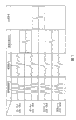
Fig. 1 is the schematic block diagram of the structure of expression first embodiment that uses supersonic imaging apparatus of the present invention;
Fig. 2 is the schematic block diagram of detailed construction of the emitter of supersonic imaging apparatus shown in Figure 1;
Fig. 3 is the schematic block diagram of detailed construction of the receptor of supersonic imaging apparatus shown in Figure 1;
Fig. 4 is the sketch map of the transfer approach of a ultrasonic beam in the supersonic imaging apparatus shown in Figure 1;
Fig. 5 is the sketch map of the operation of a sign indicating number manipulator in the supersonic imaging apparatus shown in Figure 1;
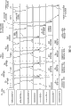
Fig. 6 is the sequential chart of the operation of expression sign indicating number manipulator shown in Figure 5;
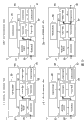
Fig. 7 is the sketch map of an example of the waveform of sign indicating number modulated received signal in the supersonic imaging apparatus shown in Figure 1 and rectification signal thereof etc.;
Fig. 8 is the sketch map of another example of the waveform of sign indicating number modulated received signal in the supersonic imaging apparatus shown in Figure 1 and rectification signal thereof etc.;
Fig. 9 is the sketch map of a comparative example of the waveform of sign indicating number modulated received signal in the supersonic imaging apparatus of prior art and rectification signal thereof etc.;
Figure 10 is the sketch map of a comparative example of the waveform of sign indicating number modulated received signal in the supersonic imaging apparatus of prior art and rectification signal thereof etc.;
Figure 11 is the sketch map of a comparative example of the waveform of sign indicating number modulated received signal in the supersonic imaging apparatus of prior art and rectification signal thereof etc.;
Figure 12 is the structure of a sign indicating number demodulator of expression second embodiment that uses supersonic imaging apparatus of the present invention and the sketch map of operation;
Figure 13 is the sequential chart of the operation of the sign indicating number demodulator among expression Figure 12;
Figure 14 is the structure of a sign indicating number demodulator of expression the 3rd embodiment that uses supersonic imaging apparatus of the present invention and the sketch map of operation;
Figure 15 is the sequential chart of the operation of the sign indicating number demodulator among expression Figure 14;
Figure 16 is the sketch map of structure of the relevant determining unit of expression the 4th embodiment that uses supersonic imaging apparatus of the present invention;
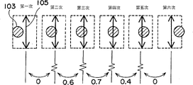
Figure 17 is the sketch map of operation of the relevant determining unit of expression the 4th embodiment that uses supersonic imaging apparatus of the present invention, and this relevant determining unit determines to be incorporated in the number of the scanning line of multi-strip scanning line by prescan;
Figure 18 is the sketch map of operation of the relevant determining unit of expression the 5th embodiment that uses supersonic imaging apparatus of the present invention, and this relevant determining unit is defined as the number of the coding exchange of a line by prescan;
Figure 19 is the sketch map of the structure of expression the 6th embodiment that uses supersonic imaging apparatus of the present invention;
Figure 20 is the schematic block diagram of detailed construction of the emitter of supersonic imaging apparatus shown in Figure 19;
Figure 21 is the schematic block diagram of detailed construction of the receptor of supersonic imaging apparatus shown in Figure 19.
The specific embodiment
[first embodiment]
First embodiment that answers supersonic imaging apparatus of the present invention will be described below.Fig. 1 is the schematic block diagram of the structure of the expression supersonic imaging apparatus of using this embodiment.This supersonic imaging apparatus comprises probe 1, emitter 3 and receptor 5.Probe 1 emission/reception ultrasound wave.Emitter 3 output 1 the driving signal that is used to pop one's head in.Receptor 5 is used to receive output from 1 the reflective echo signal of popping one's head in (below be referred to as received signal).Further, provide emission/reception separator 7 therein, be used to launch the driving signal of output spontaneous emission device 3 and be used to launch from 1 received signal that exports receptor 5 to of popping one's head in.
Between probe 1 and emission/reception separator 7, provide scan aperture switch 9.Scan aperture switch 9 is selected a transducer that the aperture is arranged of probe 1 in the middle of 1 a plurality of transducers of popping one's head in.And, signal processor 13, image processor 15 and display unit 17 wherein also are provided.Signal processor 13 is carried out the detection processing at for example exporting from a received signal of receptor 5.Image processor 15 is based on the ultrasonic figure of the signal reconstruction of being handled by signal processor 13.The ultrasonic figure that display unit 17 shows by image processor 15 reconstruct.It should be noted that the controller 37 of output command to these parts wherein also is provided.
Emitter 3 has modulation waveform selector 19, transmitted pulse maker 21 and power amplifier 23.Modulation waveform selector 19 is selected the modulating-coding coefficient of an expectation from the modulating-coding coefficient that prestores, and output modulating-coding coefficient.The modulating-coding coefficient is comprised in the modulation code and has a plurality of code elements.Transmitted pulse maker 21 is modulated emission ultrasonic signal pulse (below be referred to as basic wave) based on the modulating-coding coefficient of output automodulation mode selector 19, and the basic wave of modulate is exported as a coding driving signal.The coding of 23 pairs in power amplifier output spontaneous emission impulse generator 21 drives signal and amplifies and export emission/reception separator 7 to.It should be noted that wherein also provides mission controller 25, and its output command is given modulation waveform selector 19, transmitted pulse maker 23 and power amplifier 23.Mission controller 25 can also comprise bus control unit, depositor, selector, memorizer and buffer.
Fig. 2 is the schematic block diagram of the detailed construction of emitter 3.Modulation waveform selector 19 comprises yard selector 39 and mode selector 41.Sign indicating number selector 39 has a yard type selector 43, code length selector 45, code interval selector 47 and modulating-coding coefficient memory 49.Modulating-coding coefficient memory 49 is preserved the modulating-coding coefficient that obtains by calculated in advance.Sign indicating number type selector 43 is according to modulation code type of command selection (as the Golay sign indicating number) of output spontaneous emission controller 25.Code length selector 45 is according to the code length of the command selection modulation code of output spontaneous emission controller 25.Code length is meant the quantity that is included in a code element in the modulation code.The interval that code interval selector 47 is selected between the modulation code.Be included in the modulation code about sign indicating number type, code length and information (parameter) at interval.Transmission pulse maker 21 is read and exported to modulating-coding coefficient memory 49 to a suitable modulating-coding coefficient based on the sign indicating number type of being selected by sign indicating number type selector 43, by the code length of code length selector 45 selections, by the code interval that code interval selector 47 is selected from a plurality of modulating-coding coefficients.
It should be noted that a yard type selector 43, code length selector 45 and code interval selector 47 can comprise depositor and selector.Modulating-coding coefficient memory 49 can comprise memory element, as SRAM and DRAM.
Transmitted pulse maker 21 comprises that emission focus selector 57, emission focus postpone maker 59, transmitted pulse memorizer 61 and transmitted pulse maker 62.The emission focus selector is according to the degree of depth of the command definition emission focus of output spontaneous emission controller 25.The degree of depth of emission focus is meant that ultrasonic beam converges at the degree of depth in the object.The emission focus postpones maker 59 based on giving transmitting pulse waveform memorizer 61 by emission focal depth output pulse launch time of emission focus selector 57 definition.Pulse launch time is meant a signal, and it is time delay according to postponing launch time, and be to define for each transducer (passage) in the aperture that is included in probe 1 this time delay.Transmitted waveform memorizer 61, based on the modulating-coding coefficient of output automodulation code coefficient memorizer 49 and the basic wave of output spontaneous emission waveform selection memory 55, from selecting a suitable transmitting pulse waveform the transmitting pulse waveform that obtains in advance by calculating.
It should be noted that emission focus selector 57 can comprise depositor and selector.The emission focus postpones maker 59 can comprise shift register, selector, enumerator and frequency demultiplexer.Transmitting pulse waveform memorizer 61 can comprise memory element, as SRAM and DRAM.Transmitted pulse is given birth to device 62 can comprise digital-to-analog (D-A) changer and buffering amplifier.
Further, be enabled when output spontaneous emission focus postpones maker 59, the selecteed transmitting pulse waveform of transmitted waveform memorizer 61 outputs is to transmitted pulse maker 62, and is synchronous with sampling clock.The transmitted pulse and 62 transmitting pulse waveforms that utilize the digital-to-analog converter handle to export the digital signal of spontaneous emission impulse waveform memorizer 62 of growing up to be a useful person are transformed into analog voltage or current value, and the transmitting pulse waveform of conversion is exported to power amplifier 23 as coding driving signal.
Fig. 3 is the schematic block diagram of the detailed construction of yard demodulator 11.As shown in Figure 3, the demodulation factor selector 27 of sign indicating number demodulator 11 has demodulation code type selector 67, demodulation code length selector 69, the demodulation code tone coded coefficient memory 73 of selector 71 reconciliation at interval.Sign indicating number demodulation controller 35 wherein also is provided, and its output command is given demodulation code type selector 67, demodulation code length selector 69 and demodulation code interval selector 71.Demodulation code type selector 67 is according to the type of output from the command selection modulation code of sign indicating number demodulation controller 35.Demodulation code length selector 69 is according to the code length of output from the command selection modulation code of sign indicating number demodulation controller 35.Demodulation code interval selector 71 is according to the code interval of output between the command selection modulation code of sign indicating number demodulation controller 35.Demodulation code coefficient memorizer 73 is preserved the demodulation code coefficient that obtains by calculated in advance.Demodulator filter 29 is read and exported to demodulation code coefficient memorizer 73 to a suitable demodulation code coefficient according to the sign indicating number type of being selected by demodulation code type selector 67, by the code length of demodulation code length selector 69 selections and the code interval of being selected by demodulation code interval selector 71 from a plurality of demodulation code coefficients.Here, the parameter of the code length of comprise the sign indicating number type selected by sign indicating number type selector 43, being selected by code length selector 45 and the code interval selected by code interval selector 47 is corresponding to the parameter by the modulation code of sign indicating number selector 39 selections of modulation waveform selector 19.Demodulation code type selector 67, demodulation code length selector 69 and demodulation code interval selector 71 can comprise depositor and selector.Demodulation code coefficient memorizer 73 can have memory element, as SRAM and DRAM.
The basic operation that is obtained a ultrasonic figure by supersonic imaging apparatus will be described below.At first, be used to pop one's head in 1 coding drives signal and is generated by emitter 3.The coding driving signal that generates is input to probe 1 by the aperture of emission/reception separator 7 and transducer 9.Like this, the ultrasonic coded beams of coding is emitted to an object from probe.The ultrasound wave that is reflected by object is popped one's head in 1 to be received.The processing and amplifying that the ultrasound wave that is received is done through receptor 5 as a received signal is carried out a yard demodulation then.The received signal of demodulation is detected by signal processor 13, is reconstituted a ultrasonic figure (as B mode image and M mode image) by image processor 15.The ultrasonic figure of reconstruct is displayed on the display screen of display unit 17.
Next, be described in detail in a coding driving of generation Signal Processing process in the emitter 3.For example, a kind of yard type (as the Golay sign indicating number) at first chosen according to an order of output spontaneous emission controller 25 by sign indicating number type selector 43.Then, a code length (is 4 as code length) is chosen by code length selector 45.Then, a code interval (as wavelength X) is chosen by code interval selector 47.Here, wavelength X is meant a wavelength corresponding to the mid frequency of ultrasound transmit signal.Then, based on the sign indicating number type of being selected by sign indicating number type type device 43, by the code length of code length selector 45 selections and the code interval of being selected by code interval selector 47, a suitable modulating-coding coefficient is written into from code coefficient memorizer 49.According to the order from mission controller 25, above-mentioned processing procedure repeats by the interval of definition.
On the other hand, the basic wave of driving signal is generated by mode selector 41.For example, transmitted waveform envelope is at first chosen by envelope selector 51.Further, the number of the ripple of transmitted waveform is chosen by wave number selector 53.Based on selecteed envelope and wave number, the transmitted waveform data of expectation are launched mode selector and select.Selecteed transmitted waveform data are output to transmitting pulse waveform memorizer 61 as the basic wave that drives signal.
Then, the degree of depth of emission focus is launched focus selector 57 definition.Based on the emission focal depth that is defined, be launched focus and postpone maker 59 definition a time delay.Based on pulse launch time of the time delay that defines, postpone maker 59 from the emission focus and export transmitting pulse waveform memorizer 61 to.
Based on the modulating-coding coefficient of output automodulation code coefficient memorizer 49 and the basic wave of output spontaneous emission waveform selection memory 55, transmitting pulse waveform is launched impulse waveform memorizer 61 as a coding driving signal and selects.It is a waveform that selecteed coding drives signal, comes from the sign indicating number modulation of the basic wave with described modulating-coding coefficient.Pulse launch time that postpones maker 59 when output spontaneous emission focus is enabled (opening), and coding drives signal and is written into from transmitting pulse waveform memorizer 61.The coding that is written into drives signal and is output to transmitted pulse maker 62.Output encoder driving signal is launched impulse generator 62 and becomes an analogue signal from digital signal conversion.The coding that was transformed drives signal and is output to power amplifier 23.
Further, according to the order of output spontaneous emission controller 25, the yield value of an expectation is defined by gain controller 63.Based on the yield value of expectation, the coding of output spontaneous emission impulse generator 62 drives the gain of signal and is amplified by power amplifier 65.The coding that is exaggerated drives signal and inputs to scan aperture switch 9 by emission/reception separator 7.Specified coding drives signal and is output each transducer to the aperture of probe 1.Input coding drives signal is for conversion into a mechanical signal by each transducer ultrasound wave.The ultrasound wave that is transformed 1 is transmitted to an object as a ultrasound emission bundle from popping one's head in.The formation of ultrasound emission bundle forms by advancing along a direction, and this direction is the direction of hyperacoustic crest unanimity of being launched, the i.e. direction of the concentration of object.
At this, the combination of modulation code is described, this is characteristics of the present invention.According to this embodiment, drive in the Signal Processing process generating a coding, four modulation code A, B ,-B and-A is selected as one group.Coding drives signal and is generated by each selecteed modulation code.Afterwards, by the interval of definition, four codings that the coding emission is generated drive signal and repeat four times.More specifically, the first modulation code A and the second modulation code B be as a pair of Golay sign indicating number, chooses by the interval of the definition selector 39 that at first is encoded.Selected modulation code A and B are the modulating-coding coefficient that comprises four code elements.For example, the modulating-coding coefficient of modulation code A is (1,1,1 ,-1).The modulating-coding coefficient of modulation code B is (1,1 ,-1 ,-1).The modulating-coding coefficient of modulation code A and the modulating-coding coefficient of modulation code B are defined as orthogonal.In other words, modulation code A and modulation code B are complementary relationships.The group that has modulation code A and B in order is referred to as code set.A plurality of code elements of each among modulation code A and the B are merged, and propagate the energy of basic wave towards time shaft, and generate a coding driving signal.
Afterwards, by the interval of definition, the 3rd modulation code-B and the 4th modulation code-A is selected by sign indicating number type selector 43, code length selector 45 and code interval selector 47.Here, the polarity of the 3rd modulation code-B is opposite with the polarity of the second modulation code B.The polarity of the 4th modulation code-A is opposite with the polarity of the first modulation code A.Here, polarity is meant a phase Rotate 180 degree on the contrary.So the modulating-coding coefficient of modulation code-B is (1 ,-1,1,1).The modulating-coding coefficient of modulation code-A is (1 ,-1 ,-1,1).Have in order modulation code-B and-group of A is referred to as the code set of counter-rotating.First to fourth modulation code is collectively referred to as a sign indicating number bag.Then, based on be included in first to fourth modulation code A, B in the sign indicating number bag ,-B and-A, by the interval of definition, coding is launched/is received on the scanning line and is repeated four times.
Fig. 4 shows to encode to launch/be received on the scanning line and is repeated four times method.As shown in Figure 4, a ultrasonic beam is by the inside of conversion towards an object of scanning direction of aperture emission (scanning line), and emission repeatedly.Then, in this embodiment, carry out four emission/receptions on four each scanning lines.For example, be transmitted to first scanning line, be received corresponding to a received signal of this ultrasound emission bundle based on the first ultrasound emission bundle of modulation code A.Then, be transmitted to the there, be received corresponding to a received signal of this ultrasound emission bundle based on the second ultrasound emission bundle of modulation code B.Then, be transmitted to the there, be received corresponding to a received signal of this ultrasound emission bundle based on the 3rd ultrasound emission bundle of modulation code-B.At last, be transmitted to the there, be received corresponding to a received signal of this ultrasound emission bundle based on the 4th ultrasound emission bundle of modulation code-A.Four emission/receptions be performed in every scanning line (1,2 ... N-2, N-1, N, N+1, N+2 ...).
Processing procedure to received signal in receptor 5 is described below.As mentioned above, the ultrasound emission bundle is driven signal from 1 emission of popping one's head in by a coding, and the ultrasonic beam that is launched is at the object internal communication.Then, ultrasound emission as a reflective echo signal in the place that acoustic resistance changes, as the surface of organ, by partial reflection.A plurality of transducers that the part of reflective echo signal is popped one's head in the aperture in 1 receive.The reflective echo signal that receives is transformed into the signal of telecommunication, the signal of telecommunication that is transformed into as received signal by from pop one's head in 1 output.
Output is output to scan aperture switch 9 from 1 the received signal of popping one's head in.The received signal of output is output to receptor 5 by emission/reception separator 7.Then, input to processing procedure of each received signal experience of receptor 5, as the amplification of being undertaken by amplifier 4.For example, each received signal that is exaggerated is carried out phasing by receiving signal delayed unit 71 by receiving the focus processing.The reception focus is meant, considers the difference of received signal from a reflection sources of received signal to the propagation time of transducer, postpones by not commensurability delay by the received signal to different channels, and the phasing that the received signal of different passages is done is handled.
On the other hand, the type of modulation code is according to selecting from the order of sign indicating number modulation controller 35 by modulation format selector 67.Further, the code length of modulation code is selected by modulation code length selector 69.Further again, the code interval between the modulation code is by modulation code selector 71 selections at interval.Afterwards, based on the sign indicating number type of being selected by modulation format selector 67, by the code length of modulation code length selector 69 selections and the code interval of being selected by modulation code interval selector 71, a suitable modulating-coding coefficient is written into from modulating-coding coefficient memory 73.The modulating-coding coefficient that is written into is output to product accumulator 77.Modulating-coding coefficient that it should be noted that output be the modulating-coding coefficient selected by modulation waveform selector 19 (as, (1,1,1,1) is corresponding to the modulating-coding coefficient (1,1,1-1)) of modulation code A.The modulating-coding coefficient is a modulation code, and comprises a plurality of code elements.A plurality of code elements of demodulation code coefficient are merged, thereby assemble the energy of received signal, and demodulated received signal.
Then, the received signal of received signals signal element 75 phasings is added up by product accumulator 77.Like this, obtained received signal as a ultrasonic reception bundle.And then product accumulator multiply by the demodulation code coefficient that tone coded coefficient memory 73 is explained in output by oneself to received signal.Like this, received signal is by the sign indicating number demodulation.Being stored device 81 by the demodulated received signal preserves.
In this embodiment, the emission/reception of four codings wraps on the scanning line with a sign indicating number and is repeated.Four received signals are kept in the memorizer 81 by inferior.First to the 4th received signal that is saved is synthesized device 33 synthesizes in the sign indicating number bag for each bar scanning line, as shown in Figure 5.In other words, first to the 4th received signal is synthesized in a sign indicating number bag.
The operation that received signal is synthesized as shown in Figure 5 and Figure 6.The sketch map that Fig. 5 utilizes block diagram to make an explanation.Fig. 6 is the sketch map that utilizes sequential chart to make an explanation.(i)-(iv) among (i)-(iv) among Fig. 5 and Fig. 6 shows and modulates to received signal and synthetic operation, and described received signal is corresponding to first to fourth ultrasound emission bundle of N bar scanning line.
Shown in Fig. 5 (i) and Fig. 6 (i), corresponding to modulated wave filter 29 modulation of the received signal of the first modulation code A.Modulated received signal is stored in the linear memory 31.Then, as Fig. 5 (ii) with Fig. 6 (ii) shown in, be stored in the linear memory 31 by demodulator filter 29 corresponding to the received signal of the second modulation code B.As Fig. 5 (iii) with Fig. 6 (iii) shown in, also be stored in order in the linear memory 31 corresponding to the received signal of the 3rd modulation code-B with corresponding to the received signal of the 4th modulation code-A.Then, as Fig. 5 (iv) with Fig. 6 (iv) shown in, carry out the coding emission/reception of a sign indicating number bag, first to fourth received signal is written into from linear memory 31 subsequently.All received signals that is written into are adjusted to by signal synthesizer 85 has same time shaft.In other words, received signal is adjusted to the sampled point corresponding to the direction of the degree of depth in the object.Based on the composite coefficient of output from composite coefficient selector 83, the received signal with same time shaft is synthesized by signal synthesizer 85.Received signal after synthetic is output the signal processor 13 to the downstream.
Below, with reference to simulation result (illustration), by comparing, will describe coding received signal, sign indicating number modulated received signal (restituted signal), be derived from the synthetic received signal (demodulation composite signal) of restituted signal and be derived from the further synthetic last composite signal (composite signal) of demodulation composite signal with existing coding emission/reception technique.
[repair and show 1-1]
Even the fact that Fig. 7 shows simulation result and is reduced time sidelobe is owing to for example mobile the causing owing to health occurs in the received signal under the situation of magnification distortion.Figure shown in Figure 7 has the waveform of the received signal of encoding from left to right, first and second composite signals and the 3rd composite signal.First and second composite signals are quoted by the first and second demodulation composite signals, quote and the 3rd composite signal is synthesized signal.The longitudinal axis of figure is represented the intensity of signal.The transverse axis of figure is represented express time.Fig. 7 from the row beginning on the top show situation in turn based on first coding emission/reception of modulation code A, based on the situation of the second coding emission/reception of modulation code B, based on the encode situation of emission/reception and of the 3rd of modulation code-B based on the encode situation of emission/reception of the 4th of modulation code-A.
First to fourth coding received signal be stem from based on modulation code A, B ,-B ,-signal of the reflection of the ultrasound emission bundle of A.Referring to Fig. 7, the coding received signal has third and fourth wave amplitude, is reduced by the amplitude distortion that causes that moves owing to for example health.Like this, modulation signal also has the wave amplitude that has reduced.
Here, if there is not amplitude distortion, when first and second restituted signals are synthesized to obtain the first demodulation composite signal P1, third and fourth restituted signal is synthesized to obtain the second demodulation composite signal P2, and the first demodulation composite signal P1 and the second demodulation composite signal P2 all have the waveform that is equal to.In other words, all demodulation composite signals should come reconstruct with the impulse wave of the one-period with wavelength X.Yet, as shown in Figure 7, along the direction of time, the preceding of main lobe and after, demodulation composite signal P1 and P2 all have time sidelobe.Has equal wave amplitude and opposite polarity the time sidelobe that appears at demodulation restituted signal P1 and P2.
In this example, the further synthetic first demodulation composite signal P1 and the second demodulation composite signal P2 have drawn a composite signal, wherein eliminate mutually the time sidelobe of the time sidelobe of the first demodulation composite signal P1 and the second demodulation composite signal P2.Therefore, shown in the right column of Fig. 7, be reduced to negligible level when showing the time sidelobe of composite signal.
[illustration 1-2]
Fig. 8 shows the figure that is similar to Fig. 7, but shown situation is to appear in the received signal of encoding owing to position phase distortion that moving of health causes, rather than amplitude distortion.As shown in Figure 8, appear among each demodulation composite signal P1 and the P2 time sidelobe that causes of moving owing to health.In this example, shown in the right column of Fig. 8, demodulation composite signal P1 is conciliate the composite signal of further synthetic generation that is mixed into signal P2, it has the time sidelobe that reduces.
Appear in the coding received signal (Fig. 8) as amplitude distortion, the situation that frequency distortion appears in the coding received signal can be that same mode is handled.
[comparative example 1]
Fig. 9 is used for explaining that prior art uses the figure of the coding emission/reception of a pair of Golay sign indicating number.In this comparative example, drive signal (basic wave) generation coding driving signal by modulating one, described driving signal has modulation code A (1,1,1 ,-1) and the modulation code B (1,1 ,-1 ,-1) that is selected as the Golay sign indicating number.Each modulation code A and B all are that the code length that comprises 4 code elements is 4 sign indicating number.Modulation code A and modulation code B are complementary relationships.Modulation code A and modulation code B have orthogonality, and cancel each other out because the time sidelobe that the sign indicating number modulation causes.
Shown in the left column of Fig. 9, the first coding received signal is the ripple that is derived from based on the reflection of the ultrasound emission bundle of modulation code A.The second coding received signal is the ripple that is derived from based on the reception of the ultrasound emission bundle of modulation code B.Shown in the middle column of Fig. 9, owing to appear among the restituted signal of the demodulation that is derived from the first coding received signal time sidelobe that the sign indicating number demodulation causes.Also be like this in second restituted signal.Appear at time sidelobe in first and second restituted signals and have the wave amplitude that is equal to each other and opposite polarity.Shown in the right side row of Fig. 9, synthetic first restituted signal and second restituted signal cause a demodulation composite signal, wherein owing to eliminated each other the time sidelobe that the sign indicating number demodulation causes.As shown in Figure 9, by carrying out the coding emission/reception that has the Golay sign indicating number of prior art, because be reduced the time sidelobe that the sign indicating number demodulation causes.
Yet in the coding emission/reception that has the Golay sign indicating number of prior art, in the interval of first ultrasonic beam and second ultrasonic beam, object may move or the form of special body size may change.Like this, because the body action of a biological tissue (as, move), occurred time sidelobe.In other words, because body action comes across in the mutual-complementing code time sidelobe, typically resemble the Golay sign indicating number.
Shown in the middle column of Fig. 9, the time main lobe of first restituted signal and the time main lobe of second restituted signal have equal wave amplitude and polarity.So shown in the right side row of Fig. 9, the signal intensity of the time main lobe of demodulation composite signal derives from the signal intensity that multiply by the received signal under the situation that the emission/reception of not encoding is performed with the number of code length and coding emission/reception.For example, in this comparative example, code length is " 4 ", and the number of coding emission/reception is " 2 ".So, the signal intensity of the time main lobe of demodulation composite signal be do not have coding intensity 8 (=4 * 2) doubly.
[comparative example 2]
Figure 10 shows the figure that is similar to Fig. 9, and still, the given example of Figure 10 is, because in the interval of first ultrasonic beam and second ultrasonic beam, object has moved, so appear in the demodulation composite signal time sidelobe that causes owing to the action of health.Shown in the middle column of Figure 10, the time main lobe of first restituted signal has different signal intensitys with the time main lobe of second restituted signal, but has identical polarity.So shown in the right side row of Figure 10, the time main lobe of demodulation composite signal has reinforced signal intensity.Yet shown in the middle column of Figure 10, have opposite polarity the time sidelobe of first and second restituted signals, and have amplitude excursion to each other.So, shown in the right side of Figure 10 is existing, first and second restituted signals are synthesized, generate a demodulation composite signal, do not eliminate each other time sidelobe wherein, but exist time sidelobe.
[comparative example 3]
Figure 11 has provided a figure that is similar to Figure 10, but the state of its expression is that because the body action of object, position phase distortion comes across in the coding received signal.Situation as shown in figure 10, exist the time sidelobe of demodulation composite signal, is not eliminated.
According to this embodiment, resemble from example 1 and 2 and comparative example 1-3 obviously draw, owing to can being reduced non-linear time sidelobe that causes of the medium of object, and can be reduced the time sidelobe that causes owing to the body action of object.So the resolution of ultrasonic figure can strengthen.
In conjunction with Fig. 8 the principle that obtains advantage of the present invention is described again below.When object have body action (as, move), corresponding to the coding received signal of two modulation code A of a code character and B by demodulation, to obtain restituted signal.Synthetic the restituted signal that obtains, cause demodulation composite signal P1 (first composite signal).Be the body action that causes owing to from moving forward of object the time sidelobe that appears among the demodulation composite signal P1.Then, corresponding to two modulation code-B in opposite code character and-the coding received signal of A is by demodulation, to obtain restituted signal.Synthetic the restituted signal that obtains, cause demodulation composite signal P2 (second composite signal).Be to be equal to the signal that causes owing to body action the time sidelobe that appears among the demodulation composite signal P2, should be because signal of body action be the causing relative to oppositely moving of time sidelobe, object with reference to demodulation composite signal P1.
Demodulation composite signal P1 and demodulation composite signal P2 are combined, cause a composite signal (the 3rd composite signal), in signal, appear among demodulation composite signal P1 and the demodulation composite signal P2 owing to a certain amount of the moving of object eliminated the time sidelobe that causes each other.So it is the signal that obtains that this composite signal can be equal to object motionless substantially.In other words, be mixed into signal P2 and be synthesized when demodulation composite signal P2 conciliates, eliminate the time sidelobe of the time sidelobe of demodulation composite signal P1 and demodulation composite signal P2 each other, and this can reduce the time sidelobe that the body action owing to object causes.It should be noted that demodulation composite signal P1 can be called as the forward received signal, and demodulation composite signal P2 can be called as reverse received signal.
Further, according to this embodiment, when object carries out at the uniform velocity ideal style mobile, can eliminate each other the time sidelobe that appears in the demodulation composite signal, even when object carries out complicated moving, because also can be reduced the time sidelobe that body action causes, because move the uniform motion that can be considered in a shorter time.
More than based on first embodiment to the present invention as description, but the present invention is not limited thereto.For example, a pair of Golay sign indicating number is used as the code set that comprises two demodulation codes, various types of sign indicating numbers also can be selected, as orthogonal complement to sign indicating number (Orthogonal Complemental Paircodes, referring to IEEE, On information Theory (about information technology), vol.IT-24, No.5 Sept.1978, P.546-552).As another mode, comprise that the code character of three modulation codes also can be used.For example, when a code set comprises first to the 3rd modulation code X, Y and Z, the phase-reversal coding group can comprise the polarity four modulation code-Z opposite with the 3rd modulation code Z, the 5th modulation code-Y, the polarity four modulation code-X opposite with the first modulation code X that polarity is opposite with the second modulation code Y.In this case, modulation code-X is derived from by the position of the predetermined position number of phases to modulation code X and rotates mutually.For modulation code-Y with-Z also is the same.So it is more that can be reduced time sidelobe.And, even when the code set that comprises four modulation codes, as quadriphase sequence (Quadriphase Sequence, referring to IEICE Trans.Fundamentals, Vol.E82-a_12_2771), each modulation code in the phase-reversal coding group can define according to the mode the same with the situation with three modulation codes.In this case, when code set and phase-reversal coding group all have N modulation code, M modulation code in the phase-reversal coding group can have with code set in the opposite polarity of (N-M+1) individual modulation code, wherein, N and more than or equal to 5 natural number, M is equal to or less than 5 natural number.
In other words, a plurality of modulation codes in the phase-reversal coding group can have the position that comes from the modulation code in the code set and are rotated mutually and the position phase that obtains.So may be reduced the time sidelobe that causes owing to the body action of object, simultaneously, owing to also being reduced non-linear time sidelobe that causes of object interior media.
The intersymbol of having described modulation code above is divided into the example of λ, but code interval can become 1.5 λ or 2 λ.For example, in the time of 2 λ, the modulating-coding coefficient of modulation code A can be (1,0,1,0,1,0 ,-1), and the modulating-coding coefficient of modulation code B can be (1,0,1,0 ,-1,0 ,-1).Like this, code interval has increased, because of the influence of the response of its generation has just reduced.So can be reduced more time sidelobe.
Further, above-described example is that the modulating-coding coefficient obtains by calculated in advance and the modulating-coding coefficient is stored in the situation of modulating-coding coefficient memory 49, but the modulating-coding coefficient can be by for example CPU, based on the information of relevant modulation code, code length and code interval, calculate and obtain.Transmitted waveform can be by a CPU who is used for transmitted waveform and impulse waveform, based on the modulation code coefficient, calculates and obtains.
[second embodiment]
The second embodiment of the present invention is described below.The difference of this embodiment and first embodiment is that the received signal that obtains from a plurality of scanning lines with different directions is synthesized between scanning line.So, be omitted with being described in here of part identical among first embodiment, its difference is only described.In description, identical parts adopt identical drawing reference numeral.
Figure 12 is the structure of a sign indicating number demodulator of this embodiment of expression and the sketch map of operation.Figure 13 is the sequential chart of the operation of the sign indicating number demodulator among expression Figure 12.The sign indicating number demodulator of this embodiment optimally is the received signal that is configured between the scan synthesis line.For example, as shown in figure 12, sign indicating number demodulator 11 has envelope curve memorizer (packet line memory) 91 and envelope curve synthesizer 93, and does not have linear memory 31 and line synthesizer 33 among the embodiment 1.The output signal of demodulator filter 29 is input to envelope curve memorizer 91.The output signal of demodulator filter 29 or envelope curve memorizer 91 is input to envelope curve synthesizer 93.Sign indicating number demodulator 11 further comprises scanning line memorizer 95 and scanning line synthesizer 97.The output signal of envelope curve synthesizer 93 is input to scanning line memorizer 95.The output signal of envelope curve synthesizer 93 or scanning line memorizer 95 is input to scanning line synthesizer 97.Envelope curve memorizer 91 and scanning line memorizer 95 are controlled by sign indicating number demodulation controller 35.
The operation of the sign indicating number demodulator 11 of this embodiment is described below.As first embodiment, coding emission/reception is to comprise the code set of two modulation code A and B and comprise two modulation code-B and the phase-reversal coding group of-A is carried out by use.As (i) among Figure 12 to (iii) with Figure 13 in (i) shown in (iii), on the N scanning line, carry out first to the 3rd coding emission/reception.Like this, first to the 3rd received signal is by demodulator filter 29 demodulation.First to the 3rd received signal by demodulation is sequentially preserved by envelope curve memorizer 91.Then, on the N scanning line, carry out the 4th coding transmission/reception.Like this, as Figure 12 (iv) with Figure 13 (iv) shown in, the 4th received signal is by demodulator filter 29 demodulation.The 4th received signal by demodulation is output to envelope curve synthesizer 93.Here, first to the 3rd received signal also is written into from envelope curve memorizer 91, and is output to envelope curve synthesizer 93.Further, according to the order of output from sign indicating number demodulation controller 35, the composite coefficient of being selected by composite coefficient selector 83 is output to envelope curve synthesizer 93.Based on the composite coefficient of output, first to fourth received signal is synthetic by envelope curve synthesizer 93.The received signal that is synthesized is output to scanning line memorizer 95 and scanning line synthesizer 97.
In this way, scanning line memorizer 95 is preserved last received signal.Last received signal is from for example received signal of (N-1) scanning line.Then, when the received signal of N scanning line by when envelope curve synthesizer 93 inputs to scanning line synthesizer 97, the received signal of (N-1) scanning line is written into from swept memory 95.Here, according to the order of output from sign indicating number demodulation controller 35, the composite coefficient of being selected by composite coefficient selector 83 is output to scanning line synthesizer 97.Based on the composite coefficient of output, it is synthetic that the received signal of (N-1) scanning line and the received signal of N scanning line are scanned synthesizer line 97.Based on the received signal that is synthesized, the diagnostic image that signal processor 13 has generated corresponding to the pixel location of N scanning line.
When the received signal of (N-1) and N scanning line will be synthesized between scanning line by scanning line synthesizer 97, are (1,1) if offer the composite coefficient of scanning line synthesizer 97, received signal can be at an easy rate be synthesized with 1: 1 ratio.
As mentioned above, according to this embodiment, based on scan fraction, first scanning line (as, second scanning line of the received signal (N-1) scanning line) and no first scanning line (as, with the adjacent N scanning line of (N-1) scanning line) received signal be synthesized.Like this, can be reduced more the time sidelobe that causes owing to body action.
Further, the memorizer 81 of first embodiment is divided into envelope curve memorizer 91 and scanning line memorizer 95 in this embodiment.So linear memory can be used effectively.
Below in conjunction with example, the sign indicating number concrete example of demodulator 11 and other example of adopting this embodiment are described.
[example 2-1]
In this example, the received signal with two scanning lines of different directions has been crossed over scanning line and has been synthesized.More particularly, the execution of the coding emission/reception of (N-1) scanning line be to use a code set that comprises two modulation code A and B and comprise two modulating-coding-B and-the phase-reversal coding group of A carries out.Then, the execution of the coding emission/reception of the N line adjacent with (N-1) scanning line is to use the phase-reversal coding group of code set and reversed in order to carry out.In other words, N scanning line and the execution of the coding emission/reception of (N-1) scanning line be by opposite in sequence.
More specifically, the execution of the coding emission/reception of (N-1) scanning line be based on modulation code A, B ,-B ,-A.On the other hand, the execution of the coding emission/reception of N scanning line be based on modulation code-B ,-A, A, B.Next, the received signal of (N-1) scanning line is grown up to be a useful person 93 synthetic between Ma Bao by enclose.The received signal of N scanning line is synthesized between Ma Bao.Based on composite coefficient composite signal is done further to synthesize, produce a signal composite signal (inter-scan-line synthesis signal, scanning line border composite signal) of crossing over (N-1) and N scanning line.Based on the scanning line border composite signal that obtains, a ultrasonic figure of N scanning line is by reconstruct.
According to this example, appear at time sidelobe in the composite signal of (N-1) scanning line and be the signal that causes owing to body action that object moves forward.On the other hand, appearing at time sidelobe in the composite signal of N scanning line is the signal that causes owing to body action that object moves in the opposite direction.So, by (N-1) scanning line and N scanning line are striden the synthetic of scanning line, owing to can be eliminated each other the time sidelobe that body action causes.
It should be noted that the present invention is not limited to this example, coding emission/reception can be performed on two different scanning lines, as long as the execution of their coding emission/reception is to have different directions from each other.
[example 2-2]
In this example, divided based on four ultrasound emission bundles of a sign indicating number bag and be transmitted to the multi-strip scanning line.For example, the execution of the coding emission/reception on (N-1) scanning line is to use modulation code A and B.The execution of the coding emission/reception on the N scanning line be to use modulation code-B and-A.Then, based on a composite coefficient, the received signal of (N-1) and N scanning line is combined for every scanning line by envelope curve synthesizer 93.Stride scanning line and combine for the synthetic received signal that produces of every scanning line further is scanned line synthesizer 97 again.Based on this composite signal, corresponding to the diagnostic image of N scanning by reconstruct.In this way, for synthetic cross over many (as, two) coding of the sign indicating number bag of scanning line launches/is received on every scanning line and be repeated.
According to this example, the number of penetrating/receiving on every scanning line can reduce.So can be reduced the time sidelobe that causes owing to body action, and the frame rate of ultrasonoscopy is strengthened.
[example 2-3]
In this example, coding emission/reception is performed on one group of four scanning line.For example, the execution of the coding emission/reception of (N-2) scanning line is to use modulation code A.The execution of the coding emission/reception of (N-1) scanning line is to use modulation code B.The execution of the coding emission/reception of N scanning line is to use modulation code-B.The execution of the coding emission/reception of (N+1) scanning line is to use modulation code-A.Then, the received signal of these scanning lines is scanned line synthesizer 97 and synthesizes.Corresponding to the diagnostic image of (N+1) scanning line by reconstruct.In this way, on every scanning line, repeat for cross over many (as, four) scanning line and the coding emission/reception of generated code bag.So can be reduced the time sidelobe that causes owing to body action, and the frame rate of ultrasonic figure is strengthened.
Generally speaking, the present invention is not limited to example 2-2 and 2-3, but, ultrasonic beam corresponding to the modulation code of a code set can be divided and be transmitted to many first scanning lines, can be divided and be launched into many second scanning lines that are different from many first scanning lines at least in part corresponding to the modulation code ultrasonic beam of opposite code set.
[example 2-4]
In this example, when a plurality of ultrasonic beams based on a sign indicating number bag are divided and are transmitted to the multi-strip scanning line, be inserted between the scanning line with a virtual scan line.For example, stem from that every synthetic received signal in (N-) and the N scanning line further is scanned linear memory 95 again is synthetic, sign indicating number demodulation controller 35 changes the composite coefficient that will offer scanning line memorizer 95.Like this, the virtual scan line number has improved.So the resolution of ultrasonic figure is strengthened.More specifically, when synthesizing between (N-1) and N scanning line, composite coefficient is (1/4,3/4), (2/4,2/4) and (3/4,1/4).Like this, three insertion lines can be defined in (N-1) and N scanning line (adjacent scanning line).So because the number of virtual scan line improves, the resolution of ultrasonic figure is strengthened.
[the 3rd embodiment]
Below in conjunction with Figure 14 and Figure 15 the third embodiment of the present invention is illustrated.Figure 14 is the structure of a sign indicating number demodulator of this embodiment of expression and the sketch map of operation.Figure 15 is the sequential chart of the operation of the sign indicating number demodulator among expression Figure 14.This embodiment is similar to the sign indicating number demodulator of the 3rd embodiment, except the operational approach of the processing procedure of synthesized received signal.So the description with aforementioned same part among the 3rd embodiment is omitted, and only describes different parts.Parts same in the description use same drawing reference numeral.
As Figure 14 (ii) with Figure 15 (ii) shown in, when the second coding emission/reception is performed, the received signal of exporting from demodulator filter 29 is directly inputted into envelope curve synthesizer 93.Here, the received signal that is kept at the previous coding emission/reception in the envelope curve memorizer 91 is written into from envelope curve synthesizer 93.First received signal that is written into is synthesized in second received signal by envelope curve synthesizer 93.Received signal after synthetic is returned to envelope curve memorizer 91.Then, as Figure 14 (iii) with Figure 15 (iii) shown in, when the 3rd coding emission/reception is performed, export from the 3rd received signal of demodulator filter 29 also by further synthesize in be written into from envelope curve memorizer 91 by envelope curve synthesizer 93 synthetic synthesized received signals.As Figure 14 (iv) with Figure 15 (iv) shown in, output is further synthesized the synthesized received signal that is written in from envelope curve memorizer 91 from the 4th received signal of demodulator filter 29, and is output to signal processor 13.The advantage same with those advantages of second embodiment also can obtain in this embodiment.
[the 4th embodiment]
Be illustrated below in conjunction with accompanying drawing 16 and 17 pairs of fourth embodiment of the present invention.This embodiment is with the different of second embodiment, the number that will be divided into based on the ultrasound emission bundle of a sign indicating number bag decides by carrying out a prescan, this prescan is executed in coding emission/reception before this, use a scanning ultrasound emission bundle, be used for analyzing the dependency relation between the received signal.
Figure 16 is the sketch map of structure of the relevant determining unit of this embodiment of expression.As shown in figure 16, relevant determining unit 98 comprises memorizer 99, associative processor 100, determining unit 101 and threshold value selector 102.Memorizer 99 comprises memory element, as SRAM.Associative processor 100 comprises the computer that is used for realizing subtraction and additional calculation, for example DSP (digital signal processor) and CPU.Determining unit 101 comprises input value is compared order unit really.Threshold value selector 102 comprises selector.
In example illustrated in fig. 17, obtain a space correlation by a concrete sequence and definite method of using prescan, relevant determining unit 98.Shown in Figure 17 (A), before beginning coding emission/reception, (range ofinterest, ROI), it automatically comprises the target 103 on the display screen, or defines with the output unit of for example trace ball to define a range of interest.Then, the predetermined number (as the scanning line of along first to the 6th direction) for target 103 definition scanning lines 105 comes emission scan ultrasound emission bundle.
Then, shown in Figure 17 (B), scanning ultrasound emission bundle is from 1 along first to the 6th direction emission of popping one's head in.Like this, each ultrasound wave that appears in every scanning line is all received by probe 1.Each ultrasound wave that is received is output to relevant determining unit 98 as a plurality of received signals afterwards through the processing and amplifying of amplifier 4.Each received signal that is input to relevant determining unit 98 all is stored in the memorizer 99.Based on the received signal that is written into from memorizer 99, the correlation coefficient in the received signal is obtained by associative processor.For example, the correlation coefficient between the received signal of first and second directions here is to obtain as zero (0).Similarly, second and the correlation coefficient of third direction, third and fourth direction, the 4th and the 5th direction and the 5th and the 6th direction here be as 0.4,0.6 and 0.3.With determining unit the correlation coefficient of each acquisition and the threshold value (as 0.4) of output from threshold value selector 102 are compared.
If correlation coefficient is equal to or greater than threshold value, correlation coefficient is determined unit 101 and is defined as a virtual value.So in this embodiment, those of three directions of second to the 5th are confirmed as effective scanning line.It should be noted that threshold value can the person of being operated freely change.Each line address of the scanning line of three directions determining is exported to controller 37 from relevant determining unit 98.Then, based on the line address of output, as second embodiment, the ultrasound emission bundle that drives signal based on the coding of a bag is divided and is emitted to the scanning line of second to the 5th direction.
According to this embodiment, before coding emission/reception is performed, the space correlation of an object of detection (as, the size of object 103).Therefore, be little if determine spatial variations, cross over the multi-strip scanning line and the number of the scanning line that is synthesized can be increased.As a result, the signal sensitivity is enhanced, and/or be reduced time sidelobe.
If determine that spatial variations is big, the number of the scanning line that leap multi-strip scanning line is synthesized can reduce.Therefore, appear at haloing and fuzzy can being prevented among the ultrasonic figure, because ultrasonic waves transmitted can be radiated to target 103 reliably.
Further, according to this embodiment, cross over the receivable maximum number of the scanning line that the multi-strip scanning line is synthesized and to determine based on space correlation.So, the ultrasound emission bundle is divided into the scanning line of maximum number or less slightly line can prevents haloing among the ultrasonic figure and fuzzy, and obtain the signal sensitivity of expectation.
The example of calculating of the correlation computations coefficient of this embodiment is described below.For example, in order to obtain a correlation coefficient between received signal X1 and another received signal S2, four representative points of the equipotential mutually of received signal S1 and S2 in are mutually determined by interval at the uniform velocity.Absolute value in the difference of the received signal of the representative point of determining 1 to 4 | S1-S2| is added up.The average absolute that acquisition is added up.The meansigma methods that obtains is by the absolute value divided by a received signal | S1|.Then, the quotient of gained is deducted from 1, draw correlation coefficient.This can be expressed as:
Correlation coefficient=1-∑ | S1-S2|/4|S1| [formula 1]
More than described the 4th embodiment, the present invention is not limited thereto.For example, the such parameter of the spatial resolution of ultrasonic figure, sensitivity and frame rate can be imported and define by an input block by the operator.Under this situation,, cross over the multi-strip scanning line and the number of synthetic scanning line can be determined based on a parameter or a plurality of parameter of input.And a parameter that is defined or the space correlation of an a plurality of parameter and an object integrally determined, thereby makes the number of scanning line can be based on definite result of front and be determined.It should be noted that input block can comprise mouse and keyboard.Display unit 17 shows and is used for the GUI (graphic user interface, Graphical User Interface) of defined parameters.
In this embodiment, when carrying out prescan before beginning coding emission/reception, prescan can carry out or carry out periodically when the part that will be diagnosed change.Under this situation, when the part that will be diagnosed changes in the middle of the process of diagnosis, prescan can manually begin with a button, also can automatically begin, situation about beginning automatically is meant, based on the variation that the density data that is shown image for example takes place along with the time, automatically identify described part and shift out from target 103.And the prescan function is carried out being provided with of validation and ineffective treatment can be from an input block input.Say with summing up, the timing of carrying out prescan can be a plurality of ultrasound emission bundles, drive signal according to coding corresponding to a code set and phase-reversal coding group, divided and by from 1 timing that is emitted to before the multi-strip scanning line of popping one's head in, also can be also can be predetermined timing to its irradiation emission from the timing that the part of 1 the ultrasound emission bundle of popping one's head in changes.
Be different from formula 1, correlation coefficient can obtain based on following formula:

Wherein N is the number of sampled point,
 With
With
 It is the vector symbol of S1 and
 S2.In formula 2, the number of samples among this embodiment is " 4 ".In other words, analysis is to use the prescan ultrasonic beam to carry out on four sampled points (N=n, n+1, n+2, and n+3).Point n to n+3 is position corresponding to sampled point, and described sampled point is corresponding to the sampled point of target 103 in all sampled points.Alternatively, order (rank) correlation coefficient of Peason product-square (product-moment) correlation coefficient, Spearman or the rank correlation coefficient of Kendall also can use.In other words, the big and little relation of the quantity of the distribution of value can compare with average.
[the 5th embodiment]
Be illustrated below in conjunction with 18 pairs of fifth embodiment of the present invention of accompanying drawing.In the example of Figure 18,, obtain time correlation by using a concrete sequence and definite method of prescan, relevant determining unit 98.The difference of this embodiment and the 4th embodiment is that the number that will be emitted to the ultrasound emission bundle of a scanning line obtains by carrying out prescan before being performed in coding emission/reception on a scanning line.With being described in this and being omitted of the same part of the 4th embodiment, different parts is only described.
Shown in Figure 18 (B), at coding before emission/receptions be performed, scan the ultrasound emission bundle by from pop one's head in 1 by the interval that defines repeatedly (as, six times) be emitted to a scanning line 105.Correlation coefficient between the received signal is obtained based on the received signal that is received from probe 1 by the associative processor 100 of relevant determining unit 98.For example, when target 103 has moved a body action, first and second time, second and for the third time, the correlation coefficient between the received signal of the 3rd and the 4th time, the 4th and the 5th time and the 5th and the 6th time here obtains as 0,0.6,0.7,0.4 and 0.The correlation coefficient that obtains be determined unit 101 and output from a threshold value of threshold value selector 102 (as, 0.4) compare.Then, the correlation coefficient that is equal to or higher than threshold value is determined the unit and is defined as virtual value.Based on the virtual value that is determined, the number and the launch time of the emission/reception that carry out on a scanning line are determined.For example, in this embodiment, second and for the third time, the correlation coefficient between the received signal of the 3rd and the 4th time, the 4th and the 5th time and the 5th and the 6th time is confirmed as virtual value.So at second to the 5th time, the emission/reception of four codings will be performed by the timing of same interval with scanning ultrasound emission bundle.
According to this embodiment, one of object over time (as, move owing to one that breathes target 103 that the body action that moves causes) can be detected.Therefore, when determining it is little over time, will can be increased with the number of the coding emission/reception on a scanning line, carried out.As a result, the sensitivity of signal may be enhanced, and/or can be reduced time sidelobe.For example, based on modulation code A, B ,-B and ,-the coding emission/reception of A will be to be executed in more number of times on the scanning line, as eight times or 16 times, rather than four times based on modulation code A, B ,-B and-the repeated encoding emission/reception on a scanning line of A.
When determining is big over time, and the number of the coding emission/reception that carry out on a scanning line can be reduced.Like this, appear at haloing and fuzzy can being prevented among the ultrasonic figure, because the ultrasound emission bundle can be radiated target 103 exactly.Further, based on time correlation, the maximum that be executed in a coding emission/reception on the scanning line can receive number and can be determined.So the emission/reception of execution coding can prevent the haloing among the ultrasonic figure and blur in such scope, and realizes the signal sensitivity of expectation.
More than described the 5th embodiment, the present invention is not limited thereto.For example, the such parameter of the spatial resolution of ultrasonic figure, sensitivity level and frame rate can be imported and define by an input block by the operator.Under this situation, based on a parameter or a plurality of parameter of input, the number of the coding emission/reception that carry out on a scanning line can be determined.And a parameter that is defined or the time correlation of an a plurality of parameter and an object integrally determined, thereby the number of coding emission/reception can be determined based on definite result of front.
As in the 4th embodiment, in the present embodiment, when carrying out prescan before beginning coding emission/reception, prescan can carry out or carry out periodically when the part that will be diagnosed change.Under this situation, when the part that will be diagnosed changes in the middle of the process of diagnosis, prescan can manually begin with a button, also can automatically begin, situation about beginning automatically is meant, based on the variation that the density data that is shown image for example takes place along with the time, automatically identify described part and shift out from target.And the prescan function is carried out being provided with of validation and ineffective treatment can be from an input block input.
[the 6th embodiment]
Be illustrated below in conjunction with Figure 19 to 21 pair of the 6th example of the present invention.Figure 19 is the sketch map of structure of the ultrasonic device of this embodiment of expression.Figure 20 is the schematic block diagram of detailed construction of the emitter of this embodiment.Figure 21 is the schematic block diagram of detailed construction of the sign indicating number demodulator of this embodiment.The difference of this embodiment and example 1 is, between modulation waveform selector 19 and transmitted pulse maker 21, provide modulating wave morpheme rotary unit 87 mutually, and, between demodulation factor selector 27 and demodulator filter 29, provide demodulation factor position rotary unit 89 mutually.Therefore, different part is wherein only described in being described in this and being omitted of the part identical with first embodiment.In description, identical parts adopt identical drawing reference numeral.
As shown in figure 19, the rotary unit 87 mutually of a modulating wave morpheme between the supersonic imaging apparatus of this embodiment modulation waveform selector 19 that is included in emitter 3 and the transmitted pulse maker 21.A demodulation factor position between the demodulation factor selector 27 that this supersonic imaging apparatus also further is included in yard demodulator and the demodulator filter 29 is rotary unit 89 mutually.Here, modulating wave morpheme phase rotary unit 87 and demodulation coefficient bits mutually rotary unit 89 rotate mutually based on the frequency band execute bit of expectation.
The following describes the work of the supersonic imaging apparatus of this embodiment.At first, a plurality of modulation waveforms, as with modulation code A, B ,-B ,-the relevant modulation waveform of A, modulated waveform selector 19 is selected.Selecteed a plurality of modulation waveform is stored in the modulating wave morpheme rotary unit 87.According to the transmitting sequence that a people is scheduled to, stored modulation waveform is launched impulse generator 21 automodulation waveform position phase rotary units 87 and is written into.The modulation waveform that is written into is output to power amplifier 23.On the other hand, a plurality of demodulation code coefficients, as with modulation code A, B ,-B ,-demodulation code that A is corresponding, selected by demodulation factor position phase rotary unit 89.According to predetermined transmitting sequence, stored demodulation code coefficient is written into from demodulation factor position phase rotary unit 89.The demodulation code coefficient that is written into is output to demodulator filter 29.
According to this example, rotated mutually by the position based on the demodulation waveforms of modulation code, and 87 outputs of modulated wave morpheme phase rotary unit.In addition, rotated mutually by the position based on the demodulation code coefficient of modulation code, and by 89 outputs of demodulation factor position phase rotary unit.Like this, except having the advantage identical with the advantage of first embodiment, computational load can advantageously be reduced, because do not need each coding emission/reception all to need to calculate modulation waveform or demodulation code coefficient.
Below based on first to the 6th case description the present invention, the present invention is not limited to these.For example, according to this embodiment, the modulation code in code set for example is modulation code A and B, the modulation code in the phase-reversal coding group is-B and-A.In other words, the order setting that the modulation code in the phase-reversal coding group has opposite position phase, this derive from modulation code in the code set the rotation of a phase.So can be reduced the time sidelobe that causes owing to body action, simultaneously, owing to also being reduced non-linear time sidelobe that causes of the medium of object inside.But the present invention is not limited thereto.More specifically, the modulation code in the code set can be modulation code A and B, and the modulation code in the phase-reversal coding group can be modulation code B and A.Under this sign indicating number structure, owing to can be reduced the time sidelobe that the body action of object causes.Under this situation, except the mode that the modulation code of phase-reversal coding group is rotated, modern war embodiment of the present invention and example are applicable to any mode.It should be noted that this is applicable to that too three or more modulation is included in the situation of a code set and phase-reversal coding group bright spring day.
As disclosed at Japanese unexamined patent publication No. open file No.7-59766, each embodiment of the present invention and example also are applicable to such situation, that is, the modulation code in the code set is modulation code A and B, the modulation code in the phase-reversal coding group be modulation code-A and-B.In this case, cannot be reduced the time sidelobe that causes owing to the body action of object, but owing to can be reduced the non-linear time sidelobe that causes of the medium of object inside.It should be noted that the situation that is included in a code set and the phase-reversal coding group for three or more modulation codes also is like this.
Claims (20)
1, a kind of ultrasonic imaging method comprises:
The first coding emission/receiving step, be used for comprising wherein that by use at least two is a code set of a plurality of modulation codes of complementary relationship, basic wave is carried out the order modulation and drives signal as coding exporting probe to, and be used to launch ultrasonic beam, by the received signal of the corresponding demodulation code demodulation of modulation code in use and the code set from probe output;
Be used for obtaining the step of first composite signal by the restituted signal that demodulation produced of the synthetic first coding emission/receiving step;
The second coding emission/receiving step, be used for comprising a phase-reversal coding group of a plurality of modulation codes with order opposite with the modulation code of code set by use, basic wave is carried out the order modulation and drives signal as coding exporting probe to, and be used to launch ultrasonic beam, by the received signal of the corresponding demodulation code demodulation of modulation code in use and the phase-reversal coding group from probe output;
Be used for obtaining the step of second composite signal by the restituted signal that demodulation produced of the synthetic second coding emission/receiving step;
Be used for obtaining the step of the 3rd composite signal by synthetic first composite signal and second composite signal; With
Come the step of the ultrasonic figure of reconstruct based on the 3rd composite signal.
2, ultrasonic imaging method as claimed in claim 1 is characterized in that, the position of a plurality of modulation codes in the phase-reversal coding group is that the position by the modulation code in the rotary coding group obtains mutually mutually.
3, ultrasonic imaging method as claimed in claim 2 is characterized in that, carries out step that obtains first composite signal and the step that obtains second composite signal after emission/receiving step is encoded in the first coding emission/reception and second.
4, ultrasonic imaging method as claimed in claim 2 is characterized in that, carries out the first coding emission/receiving step and the second coding emission/receiving step at different scanning lines.
5, ultrasonic imaging method as claimed in claim 2, it is characterized in that, the first coding emission/receiving step comprises that the corresponding ultrasonic beam of modulation code in handle and the code set cuts apart and be emitted to a plurality of first scanning lines, the second coding emission/receiving step comprises that the corresponding ultrasonic beam of modulation code in handle and the phase-reversal coding group cuts apart and be emitted to a plurality of second scanning lines, and described a plurality of second scanning lines are different with a plurality of first scanning lines to small part.
6, ultrasonic imaging method as claimed in claim 2, it is characterized in that, when code set comprised first modulation code and second modulation code, the phase-reversal coding group comprised in order: with opposite polarity the 3rd modulation code of second modulation code and with opposite polarity the 4th modulation code of first modulation code.
7, ultrasonic imaging method as claimed in claim 2, it is characterized in that, when code set comprised first to the 3rd modulation code, the phase-reversal coding group comprised in order: with opposite polarity the 4th modulation code of the 3rd modulation code, with opposite polarity the 5th modulation code of second modulation code and with opposite polarity the 6th modulation code of first modulation code.
8, ultrasonic imaging method as claimed in claim 2, it is characterized in that, when code set comprised first to fourth modulation code, the phase-reversal coding group comprised in order: with opposite polarity the 5th modulation code of the 4th modulation code, with opposite polarity the 6th modulation code of the 3rd modulation code, with opposite polarity the 7th modulation code of second modulation code and with opposite polarity the 8th modulation code of first modulation code.
9, ultrasonic imaging method as claimed in claim 2, it is characterized in that, when code set and phase-reversal coding group include N modulation code, M modulation code in the phase-reversal coding group have with code set in the opposite polarity polarity of N-M+1 modulation code, wherein N is equal to or greater than 5 natural number, and M is the natural number that is equal to or less than N.
10, ultrasonic imaging method as claimed in claim 2 is characterized in that, code set comprises a pair of Golay sign indicating number.
11, a kind of method for ultrasonic imaging possesses following steps:
The first coding emission/receiving step, be used for comprising wherein that by use at least two is a code set of a plurality of modulation codes of complementary relationship, basic wave is carried out the order modulation and drives signal as coding exporting probe to, and be used to launch ultrasonic beam, by the received signal of the corresponding demodulation code demodulation of modulation code in use and the code set from probe output;
Be used for obtaining the step of first composite signal by the restituted signal that demodulation produced of the synthetic first coding emission/receiving step;
The second coding emission/receiving step, be used for comprising a phase-reversal coding group of a plurality of modulation codes with order opposite with the modulation code of code set by use, basic wave is carried out the order modulation and drives signal as coding exporting probe to, and be used to launch ultrasonic beam, by the received signal of the corresponding demodulation code demodulation of modulation code in use and the phase-reversal coding group from probe output;
Be used for obtaining the step of second composite signal by the restituted signal that demodulation produced of the synthetic second coding emission/receiving step;
Be used for obtaining the step of the 3rd composite signal by synthetic first composite signal and second composite signal; With
Come the step of the ultrasonic figure of reconstruct based on the 3rd composite signal;
The position of a plurality of modulation codes in the described phase-reversal coding group is set at the relation that obtains mutually by the modulation code in the rotary coding group mutually;
For two different scanning lines, allow the execution sequence of described first coding emission/receiving step and the described second coding emission/receiving step come to carry out respectively the described first coding emission/receiving step and the second coding emission/receiving step each other on the contrary;
In the step of the step of described acquisition first composite signal and described acquisition second composite signal,, obtain two described first composite signals and two described second composite signals respectively for described two scanning lines;
In the step of described acquisition the 3rd composite signal, synthetic respectively two described first composite signals and two described second composite signals that obtained obtain described the 3rd composite signal by each roots of described two scanning lines;
In the step of the ultrasonic figure of described reconstruct, will synthesize the ultrasonic figure of reconstruct by described the 3rd composite signal that each root obtained of described two scanning lines.
12, a kind of supersonic imaging apparatus comprises, is used to launch/receive hyperacoustic probe; Discharger for the probe output drive signal; Processing is from the receiving system of the received signal of probe output; Image processing apparatus based on the ultrasonic figure of composite signal reconstruct that exports from receptor; Show the display device of the ultrasonic figure of reconstruct; And, the control device of control discharger, receiving system, image processing apparatus and display device,
Wherein, discharger comprises the device that generates code set and phase-reversal coding group, and described code set comprises a plurality of modulation codes, and wherein at least two is complementary relationship, described phase-reversal coding group comprises a plurality of modulation codes, and wherein modulation code is provided with the order and the reversed in order of code set; Discharger also comprises with the information of code set and phase-reversal coding group modulates and generates the device that coding drives signal to basic wave; And
Receiving system comprise use with code set in each modulation code corresponding each demodulation code come the device of each received signal of demodulation, described each received signal is corresponding to being driven signal by the coding of having been modulated with code set; Receiving system also comprise synthetic by demodulation signal and generate the device of first composite signal, and use with the phase-reversal coding group in each modulation code corresponding each demodulation code come the device of each received signal of demodulation, described each received signal is corresponding to being driven signal by the coding of having been modulated with the phase-reversal coding group; Receiving system also comprise synthetic by demodulation signal and generate the device of second composite signal, and the device that from first composite signal and second composite signal, generates the 3rd composite signal.
13, supersonic imaging apparatus as claimed in claim 12 is characterized in that, the position of a plurality of modulation codes in the phase-reversal coding group is that the position by the modulation code in the rotary coding group obtains mutually mutually.
14, supersonic imaging apparatus as claimed in claim 12, it is characterized in that, the corresponding coding of discharger utilization and code set and phase-reversal coding group drives signal a plurality of first ultrasound emission bundles is emitted to first scanning line from probe, the group order that utilization is exchanged according to code set and phase-reversal coding group is driven signal by the synthetic coding of order a plurality of second ultrasound emission bundles is emitted to second scanning line from probe, and described second scanning line is different from first scanning line; And
Receiving system handle and the corresponding received signal of the first ultrasound emission bundle and with the corresponding received signal of the second ultrasound emission bundle to carry out demodulation synthetic then.
15, supersonic imaging apparatus as claimed in claim 12, it is characterized in that, the corresponding coding of discharger utilization and code set drives signal a plurality of first ultrasound emission bundles is emitted to first scanning line from probe, utilize with the corresponding coding driving of phase-reversal coding group signal a plurality of second ultrasound emission bundles are emitted to second scanning line from probe, described second scanning line is different from first scanning line; And
Receiving system handle and the corresponding received signal of the first ultrasound emission bundle and with the corresponding received signal of the second ultrasound emission bundle to carry out demodulation synthetic then.
16, supersonic imaging apparatus as claimed in claim 12 is characterized in that, the corresponding coding of discharger utilization and code set and phase-reversal coding group drives signal cutting apart and be emitted to the multi-strip scanning line from a plurality of ultrasound emission bundles of probe emission; And
The receiving system handle carries out demodulation with the corresponding received signal of ultrasound emission bundle and synthesizes then.
17, supersonic imaging apparatus as claimed in claim 12, it is characterized in that, when utilization and code set and the corresponding coding driving of phase-reversal coding group signal, will be when a plurality of ultrasound emission bundles of probe emission to be cut apart and be emitted to the multi-strip scanning line, discharger is cut apart and emission scan ultrasonic beam bar scanning line at the most; And
Receiving system comprises the relevant device of determining, the described relevant space correlation of determining relevant, the acquisition object between device analysis and the corresponding received signal of scanning ultrasonic beam, determines to be used for to cut apart the number of the scanning line of a plurality of ultrasound emission bundles based on space correlation.
18, supersonic imaging apparatus as claimed in claim 12, it is characterized in that, when utilization and code set and the corresponding coding driving of phase-reversal coding group signal, in the time of will repeatedly be emitted to scanning line from a plurality of ultrasound emission bundles of probe emission, discharger repeatedly the emission scan ultrasonic beam to scanning line; And
Receiving system comprises the relevant device of determining, describedly relevantly determine relevant, the time correlation that obtains object between device analysis and the corresponding received signal of scanning ultrasonic beam, determine to be emitted to based on time correlation scanning line the ultrasound emission bundle emitting times with launch at least one in the two of timing.
19, supersonic imaging apparatus as claimed in claim 12, it is characterized in that, discharger wherein has modulating wave morpheme phase rotary apparatus, and described modulating wave morpheme phase rotary apparatus according to the position of each modulating-coding coefficient rotation modulating wave of each modulating wave mutually and rotate the position phase of modulation waveform.
20, supersonic imaging apparatus as claimed in claim 12, it is characterized in that, receiving system wherein has demodulation code coefficient position phase rotary apparatus, the position phase that described demodulation code coefficient position phase rotary apparatus rotates each demodulation code coefficient of each demodulation code, and the demodulation code coefficient that rotates through mutually based on the position is carried out demodulation.
Applications Claiming Priority (2)
| Application Number | Priority Date | Filing Date | Title |
|---|---|---|---|
| JP2003001336A JP4269145B2 (en) | 2003-01-07 | 2003-01-07 | Ultrasonic diagnostic equipment |
| JP1336/2003 | 2003-01-07 |
Publications (2)
| Publication Number | Publication Date |
|---|---|
| CN1756509A CN1756509A (en) | 2006-04-05 |
| CN100475148C true CN100475148C (en) | 2009-04-08 |
Family
ID=32708806
Family Applications (1)
| Application Number | Title | Priority Date | Filing Date |
|---|---|---|---|
| CNB2003801101300A Expired - Fee Related CN100475148C (en) | 2003-01-07 | 2003-12-26 | Ultrasonographic method and ultrasonographic device |
Country Status (6)
| Country | Link |
|---|---|
| US (1) | US7354400B2 (en) |
| EP (1) | EP1582149B1 (en) |
| JP (1) | JP4269145B2 (en) |
| CN (1) | CN100475148C (en) |
| DE (1) | DE60331861D1 (en) |
| WO (1) | WO2004060167A1 (en) |
Families Citing this family (39)
| Publication number | Priority date | Publication date | Assignee | Title |
|---|---|---|---|---|
| US8075558B2 (en) * | 2002-04-30 | 2011-12-13 | Surgrx, Inc. | Electrosurgical instrument and method |
| US7311709B2 (en) * | 2001-10-22 | 2007-12-25 | Surgrx, Inc. | Electrosurgical instrument and method of use |
| US20050096544A1 (en) * | 2003-10-30 | 2005-05-05 | Xiaohui Hao | Method and apparatus for single transmission Golay coded excitation |
| JP4646808B2 (en) * | 2003-12-02 | 2011-03-09 | 株式会社日立メディコ | Ultrasonic diagnostic equipment |
| US7955331B2 (en) * | 2004-03-12 | 2011-06-07 | Ethicon Endo-Surgery, Inc. | Electrosurgical instrument and method of use |
| WO2006013484A1 (en) * | 2004-07-29 | 2006-02-09 | Koninklijke Philips Electronics N.V. | Enhanced bit mapping for digital interface of a wireless communication equipment in multi-time slot and multi-mode operation |
| US7654148B2 (en) * | 2005-06-22 | 2010-02-02 | Lockheed Martin Corporation | Ultrasound communication system for metal structure and related methods |
| US20070239002A1 (en) * | 2005-12-28 | 2007-10-11 | Alam Sheikh K | Superfast, High-Resolution Ultrasonic Imaging Using Coded Excitation |
| JP5404390B2 (en) * | 2007-04-24 | 2014-01-29 | パナソニック株式会社 | Ultrasonic diagnostic equipment |
| CN101411625B (en) * | 2007-10-15 | 2012-07-25 | 深圳迈瑞生物医疗电子股份有限公司 | Method for modulating and transmitting ultrasonic system bipolar pulse |
| US20100036370A1 (en) * | 2008-08-07 | 2010-02-11 | Al Mirel | Electrosurgical instrument jaw structure with cutting tip |
| US8855101B2 (en) * | 2010-03-09 | 2014-10-07 | The Nielsen Company (Us), Llc | Methods, systems, and apparatus to synchronize actions of audio source monitors |
| US8509882B2 (en) | 2010-06-08 | 2013-08-13 | Alivecor, Inc. | Heart monitoring system usable with a smartphone or computer |
| US8700137B2 (en) | 2012-08-30 | 2014-04-15 | Alivecor, Inc. | Cardiac performance monitoring system for use with mobile communications devices |
| US9351654B2 (en) | 2010-06-08 | 2016-05-31 | Alivecor, Inc. | Two electrode apparatus and methods for twelve lead ECG |
| DE102010033210A1 (en) * | 2010-08-03 | 2012-02-09 | Valeo Schalter Und Sensoren Gmbh | Method for operating an ultrasonic sensor of a driver assistance system in a motor vehicle, driver assistance system and motor vehicle |
| TWI551071B (en) * | 2010-12-16 | 2016-09-21 | 李百祺 | Wireless power transmission system, wireless power transmitting apparatus and wireless power receiving apparatus |
| KR101460692B1 (en) * | 2011-06-09 | 2014-11-13 | 삼성전자주식회사 | Apparatus for driving 2 dimensional transducer-array, medical imaging system and method for driving 2 dimensional transducer-array |
| AU2012332817B2 (en) | 2011-10-28 | 2017-03-30 | Decision Sciences International Corporation | Spread spectrum coded waveforms in ultrasound imaging |
| WO2014074913A1 (en) | 2012-11-08 | 2014-05-15 | Alivecor, Inc. | Electrocardiogram signal detection |
| WO2014107700A1 (en) | 2013-01-07 | 2014-07-10 | Alivecor, Inc. | Methods and systems for electrode placement |
| US9254092B2 (en) | 2013-03-15 | 2016-02-09 | Alivecor, Inc. | Systems and methods for processing and analyzing medical data |
| US9247911B2 (en) | 2013-07-10 | 2016-02-02 | Alivecor, Inc. | Devices and methods for real-time denoising of electrocardiograms |
| JP2015037535A (en) * | 2013-07-16 | 2015-02-26 | コニカミノルタ株式会社 | Ultrasonic signal processor, ultrasonic signal processing method and computer-readable non-temporary recording medium |
| US9844359B2 (en) | 2013-09-13 | 2017-12-19 | Decision Sciences Medical Company, LLC | Coherent spread-spectrum coded waveforms in synthetic aperture image formation |
| US10447410B2 (en) | 2013-12-02 | 2019-10-15 | Board Of Trustees Of Michigan State University | Ultrasonic communication system |
| US9420956B2 (en) | 2013-12-12 | 2016-08-23 | Alivecor, Inc. | Methods and systems for arrhythmia tracking and scoring |
| JP6212638B2 (en) * | 2014-06-26 | 2017-10-11 | 株式会社日立製作所 | Ultrasonic imaging device |
| US9931157B2 (en) | 2014-09-15 | 2018-04-03 | Ethicon Llc | Methods and devices for creating thermal zones within an electrosurgical instrument |
| KR20180096493A (en) | 2015-02-25 | 2018-08-29 | 디시전 사이선씨즈 메디컬 컴패니, 엘엘씨 | Acoustic signal transmission contact medium and coupling medium |
| JP6498325B2 (en) | 2015-05-13 | 2019-04-10 | アライヴコア・インコーポレーテッド | Discrepancy monitoring |
| JP6410944B2 (en) * | 2015-08-06 | 2018-10-24 | 株式会社日立製作所 | Ultrasonic imaging apparatus and ultrasonic imaging method |
| JP6755308B2 (en) | 2015-10-08 | 2020-09-16 | ディスィジョン サイエンシズ メディカル カンパニー,エルエルシー | Acoustic orthopedic tracking system and method |
| US10314645B2 (en) | 2016-03-16 | 2019-06-11 | Ethicon Llc | Surgical end effectors with increased stiffness |
| US11185305B2 (en) * | 2016-06-30 | 2021-11-30 | Koninklijke Philips N.V. | Intertial device tracking system and method of operation thereof |
| US10727923B2 (en) * | 2016-10-24 | 2020-07-28 | RF Pixels, Inc. | Multi-antenna beam forming and spatial multiplexing transceiver |
| WO2020219705A1 (en) | 2019-04-23 | 2020-10-29 | Allan Wegner | Semi-rigid acoustic coupling articles for ultrasound diagnostic and treatment applications |
| JP2023549818A (en) | 2020-11-13 | 2023-11-29 | ディスィジョン サイエンシズ メディカル カンパニー,エルエルシー | System and method for synthetic aperture ultrasound imaging of objects |
| CN114137082B (en) * | 2021-11-26 | 2022-06-28 | 中国科学院合肥物质科学研究院 | Automatic ultrasonic imaging detection method and system for six-axis mechanical arm |
Family Cites Families (8)
| Publication number | Priority date | Publication date | Assignee | Title |
|---|---|---|---|---|
| US4937580A (en) * | 1988-05-19 | 1990-06-26 | Trustees Of Dartmouth College | Geophysical radar apparatus and method |
| JPH01303135A (en) * | 1988-05-31 | 1989-12-07 | Yokogawa Medical Syst Ltd | Dispersion compressing system pulse echo system transmitting receiving device |
| JP3222648B2 (en) | 1993-08-25 | 2001-10-29 | ジーイー横河メディカルシステム株式会社 | Medical ultrasonic dispersion compression transmission / reception method and medical ultrasonic dispersion compression transmission / reception device |
| US6113545A (en) * | 1998-04-20 | 2000-09-05 | General Electric Company | Ultrasonic beamforming with improved signal-to-noise ratio using orthogonal complementary sets |
| US6491631B2 (en) * | 2001-01-11 | 2002-12-10 | General Electric Company | Harmonic golay-coded excitation with differential pulsing for diagnostic ultrasound imaging |
| US6487433B2 (en) * | 2001-01-08 | 2002-11-26 | General Electric Company | Method and apparatus using golay-coded excitation for echocardiology |
| KR100393370B1 (en) | 2001-04-25 | 2003-07-31 | 주식회사 메디슨 | Ultrasound imaging method and apparatus using orthogonal golay codes |
| JP2003010178A (en) * | 2001-07-03 | 2003-01-14 | Toshiba Corp | Ultrasonograph |
-
2003
- 2003-01-07 JP JP2003001336A patent/JP4269145B2/en not_active Expired - Fee Related
- 2003-12-26 DE DE60331861T patent/DE60331861D1/en not_active Expired - Lifetime
- 2003-12-26 US US10/541,452 patent/US7354400B2/en not_active Expired - Fee Related
- 2003-12-26 EP EP03786362A patent/EP1582149B1/en not_active Expired - Fee Related
- 2003-12-26 WO PCT/JP2003/016935 patent/WO2004060167A1/en active Application Filing
- 2003-12-26 CN CNB2003801101300A patent/CN100475148C/en not_active Expired - Fee Related
Non-Patent Citations (2)
| Title |
|---|
| Golay Codes for Simultaneous Multi-mode Operation inPhased Arrays. B. B. LEE, E. S. Furgason.IEEE Ultrasonics Symposium. 1982 |
| Golay Codes for Simultaneous Multi-mode Operation inPhased Arrays. B. B. LEE, E. S. Furgason.IEEE Ultrasonics Symposium. 1982 * |
Also Published As
| Publication number | Publication date |
|---|---|
| CN1756509A (en) | 2006-04-05 |
| EP1582149A1 (en) | 2005-10-05 |
| EP1582149A4 (en) | 2006-05-24 |
| JP2004209087A (en) | 2004-07-29 |
| DE60331861D1 (en) | 2010-05-06 |
| JP4269145B2 (en) | 2009-05-27 |
| EP1582149B1 (en) | 2010-03-24 |
| US20060173305A1 (en) | 2006-08-03 |
| WO2004060167A1 (en) | 2004-07-22 |
| US7354400B2 (en) | 2008-04-08 |
Similar Documents
| Publication | Publication Date | Title |
|---|---|---|
| CN100475148C (en) | Ultrasonographic method and ultrasonographic device | |
| KR100742475B1 (en) | Enhanced tissue-generated harmonic imaging using coded excitation | |
| CN101491450B (en) | Synchronized combining for contrast agent enhanced medical diagnostic ultrasound imaging | |
| Wagner et al. | Compressed beamforming in ultrasound imaging | |
| US6048315A (en) | Method and apparatus for ultrasonic synthetic transmit aperture imaging using orthogonal complementary codes | |
| US6491631B2 (en) | Harmonic golay-coded excitation with differential pulsing for diagnostic ultrasound imaging | |
| US6050947A (en) | Method and apparatus for harmonic tissue imaging and contrast imaging using coded transmission | |
| CN1218174C (en) | Supersonic imaging system with ultrasound formed by using single-pole or two-pole coding excited wave beam | |
| CN105120759B (en) | System and method for producing image from rotation intravascular ultrasound equipment | |
| CN106102588A (en) | Ultrasound grayscale imaging system and method | |
| CN106210719B (en) | System for ultrasonic imaging | |
| CN107661120A (en) | Picture is moved into using multiple parallel reception wave beams | |
| Hager et al. | Ekho: A 30.3 W, 10k-channel fully digital integrated 3-D beamformer for medical ultrasound imaging achieving 298M focal points per second | |
| JPS6115375B2 (en) | ||
| US6572550B2 (en) | Ultrasonic diagnosis device | |
| JP2004166745A (en) | Ultrasonic diagnostic equipment | |
| JP2004113693A (en) | Ultrasonic imaging instrument and ultrasonic imaging method | |
| JP4666815B2 (en) | Ultrasonic diagnostic equipment | |
| JP2011218049A (en) | Ultrasonic diagnostic apparatus | |
| JPH08173431A (en) | Ultrasonic diagnostic device | |
| Jensen et al. | P3H-3 Parametric Beamformer for Synthetic Aperture Ultrasound Imaging | |
| US4922422A (en) | Method and apparatus for selective suppression of portions of an echographic signal to improve image reconstruction | |
| CN101411627B (en) | Frame combination as well as related method for processing frames and reusing device | |
| WO2015129351A1 (en) | Ultrasound imaging apparatus | |
| Ecarlat et al. | Get Ready to Spy on Ultrasound: Meet ultraspy |
Legal Events
| Date | Code | Title | Description |
|---|---|---|---|
| C06 | Publication | ||
| PB01 | Publication | ||
| C10 | Entry into substantive examination | ||
| SE01 | Entry into force of request for substantive examination | ||
| C14 | Grant of patent or utility model | ||
| GR01 | Patent grant | ||
| CF01 | Termination of patent right due to non-payment of annual fee | ||
| CF01 | Termination of patent right due to non-payment of annual fee |
Granted publication date: 20090408 Termination date: 20161226 |