CN101295515A - Magnetic recording disk with identical servo patterns formed on each disk surface by single master template and disk drive using the disk - Google Patents
Magnetic recording disk with identical servo patterns formed on each disk surface by single master template and disk drive using the disk Download PDFInfo
- Publication number
- CN101295515A CN101295515A CNA2008100820715A CN200810082071A CN101295515A CN 101295515 A CN101295515 A CN 101295515A CN A2008100820715 A CNA2008100820715 A CN A2008100820715A CN 200810082071 A CN200810082071 A CN 200810082071A CN 101295515 A CN101295515 A CN 101295515A
- Authority
- CN
- China
- Prior art keywords
- servo
- field
- magnetic
- pattern
- sector
- Prior art date
- Legal status (The legal status is an assumption and is not a legal conclusion. Google has not performed a legal analysis and makes no representation as to the accuracy of the status listed.)
- Pending
Links
- 238000001514 detection method Methods 0.000 claims abstract description 9
- 239000000696 magnetic material Substances 0.000 claims description 19
- 239000000463 material Substances 0.000 claims description 8
- 238000000034 method Methods 0.000 claims description 8
- 230000015572 biosynthetic process Effects 0.000 claims description 4
- 230000008878 coupling Effects 0.000 claims 2
- 238000010168 coupling process Methods 0.000 claims 2
- 238000005859 coupling reaction Methods 0.000 claims 2
- 238000005070 sampling Methods 0.000 abstract description 2
- 101150020445 CYLC1 gene Proteins 0.000 description 17
- 102100036233 Cylicin-1 Human genes 0.000 description 17
- 238000000059 patterning Methods 0.000 description 11
- HHNFORCFJOVQNF-UHFFFAOYSA-N cyl-1 Chemical compound N1C(=O)C(CCCCCC(=O)C2OC2)NC(=O)C2CCCN2C(=O)C(C(C)CC)NC(=O)C1CC1=CC=C(OC)C=C1 HHNFORCFJOVQNF-UHFFFAOYSA-N 0.000 description 8
- 238000005516 engineering process Methods 0.000 description 6
- 239000010410 layer Substances 0.000 description 6
- 238000012986 modification Methods 0.000 description 5
- 230000004048 modification Effects 0.000 description 5
- 239000000758 substrate Substances 0.000 description 5
- WANLLPADDCXPGO-WMKJBNATSA-N (6r,9s,12s)-3-[(2s)-butan-2-yl]-6-[(4-methoxyphenyl)methyl]-9-[6-(oxiran-2-yl)-6-oxohexyl]-1,4,7,10-tetrazabicyclo[10.4.0]hexadecane-2,5,8,11-tetrone Chemical compound C([C@@H]1C(=O)NC(C(N2CCCC[C@H]2C(=O)N[C@@H](CCCCCC(=O)C2OC2)C(=O)N1)=O)[C@@H](C)CC)C1=CC=C(OC)C=C1 WANLLPADDCXPGO-WMKJBNATSA-N 0.000 description 4
- 101100117391 Arabidopsis thaliana DPB2 gene Proteins 0.000 description 4
- 101100025691 Arabidopsis thaliana NAGLU gene Proteins 0.000 description 4
- 101150080636 CYLC2 gene Proteins 0.000 description 4
- WANLLPADDCXPGO-UHFFFAOYSA-N Cyl-2 Natural products N1C(=O)C(CCCCCC(=O)C2OC2)NC(=O)C2CCCCN2C(=O)C(C(C)CC)NC(=O)C1CC1=CC=C(OC)C=C1 WANLLPADDCXPGO-UHFFFAOYSA-N 0.000 description 4
- 102100024257 Cylicin-2 Human genes 0.000 description 4
- 101100441845 Oryza sativa subsp. japonica CYL1 gene Proteins 0.000 description 4
- 101100441847 Oryza sativa subsp. japonica CYL2 gene Proteins 0.000 description 4
- 238000005452 bending Methods 0.000 description 4
- 230000005415 magnetization Effects 0.000 description 4
- 230000008569 process Effects 0.000 description 4
- 238000010586 diagram Methods 0.000 description 3
- 235000013399 edible fruits Nutrition 0.000 description 3
- 238000001459 lithography Methods 0.000 description 3
- 238000007639 printing Methods 0.000 description 3
- 238000012546 transfer Methods 0.000 description 3
- 238000004590 computer program Methods 0.000 description 2
- 238000013500 data storage Methods 0.000 description 2
- 229920000642 polymer Polymers 0.000 description 2
- 238000001556 precipitation Methods 0.000 description 2
- 238000012545 processing Methods 0.000 description 2
- 239000011241 protective layer Substances 0.000 description 2
- 230000007704 transition Effects 0.000 description 2
- BYHQTRFJOGIQAO-GOSISDBHSA-N 3-(4-bromophenyl)-8-[(2R)-2-hydroxypropyl]-1-[(3-methoxyphenyl)methyl]-1,3,8-triazaspiro[4.5]decan-2-one Chemical compound C[C@H](CN1CCC2(CC1)CN(C(=O)N2CC3=CC(=CC=C3)OC)C4=CC=C(C=C4)Br)O BYHQTRFJOGIQAO-GOSISDBHSA-N 0.000 description 1
- 102100036601 Aggrecan core protein Human genes 0.000 description 1
- 101100064323 Arabidopsis thaliana DTX47 gene Proteins 0.000 description 1
- 101000840469 Arabidopsis thaliana Isochorismate synthase 1, chloroplastic Proteins 0.000 description 1
- 101150026676 SID1 gene Proteins 0.000 description 1
- 108091006419 SLC25A12 Proteins 0.000 description 1
- 108091006418 SLC25A13 Proteins 0.000 description 1
- 230000006978 adaptation Effects 0.000 description 1
- 239000000654 additive Substances 0.000 description 1
- 230000000996 additive effect Effects 0.000 description 1
- 230000003321 amplification Effects 0.000 description 1
- 230000008901 benefit Effects 0.000 description 1
- 230000005540 biological transmission Effects 0.000 description 1
- 230000008859 change Effects 0.000 description 1
- 230000000295 complement effect Effects 0.000 description 1
- 238000007796 conventional method Methods 0.000 description 1
- 230000008021 deposition Effects 0.000 description 1
- 238000013461 design Methods 0.000 description 1
- 238000010894 electron beam technology Methods 0.000 description 1
- 239000011888 foil Substances 0.000 description 1
- 238000002955 isolation Methods 0.000 description 1
- 230000005381 magnetic domain Effects 0.000 description 1
- 230000005389 magnetism Effects 0.000 description 1
- 238000004519 manufacturing process Methods 0.000 description 1
- 239000003550 marker Substances 0.000 description 1
- 239000011159 matrix material Substances 0.000 description 1
- 238000003199 nucleic acid amplification method Methods 0.000 description 1
- 238000012552 review Methods 0.000 description 1
- 239000007787 solid Substances 0.000 description 1
- 230000003068 static effect Effects 0.000 description 1
- 238000003860 storage Methods 0.000 description 1
- 230000000699 topical effect Effects 0.000 description 1
Images


Classifications
-
- G—PHYSICS
- G11—INFORMATION STORAGE
- G11B—INFORMATION STORAGE BASED ON RELATIVE MOVEMENT BETWEEN RECORD CARRIER AND TRANSDUCER
- G11B20/00—Signal processing not specific to the method of recording or reproducing; Circuits therefor
- G11B20/10—Digital recording or reproducing
- G11B20/12—Formatting, e.g. arrangement of data block or words on the record carriers
-
- G—PHYSICS
- G11—INFORMATION STORAGE
- G11B—INFORMATION STORAGE BASED ON RELATIVE MOVEMENT BETWEEN RECORD CARRIER AND TRANSDUCER
- G11B5/00—Recording by magnetisation or demagnetisation of a record carrier; Reproducing by magnetic means; Record carriers therefor
- G11B5/86—Re-recording, i.e. transcribing information from one magnetisable record carrier on to one or more similar or dissimilar record carriers
- G11B5/865—Re-recording, i.e. transcribing information from one magnetisable record carrier on to one or more similar or dissimilar record carriers by contact "printing"
-
- B—PERFORMING OPERATIONS; TRANSPORTING
- B82—NANOTECHNOLOGY
- B82Y—SPECIFIC USES OR APPLICATIONS OF NANOSTRUCTURES; MEASUREMENT OR ANALYSIS OF NANOSTRUCTURES; MANUFACTURE OR TREATMENT OF NANOSTRUCTURES
- B82Y10/00—Nanotechnology for information processing, storage or transmission, e.g. quantum computing or single electron logic
-
- G—PHYSICS
- G11—INFORMATION STORAGE
- G11B—INFORMATION STORAGE BASED ON RELATIVE MOVEMENT BETWEEN RECORD CARRIER AND TRANSDUCER
- G11B21/00—Head arrangements not specific to the method of recording or reproducing
- G11B21/02—Driving or moving of heads
-
- G—PHYSICS
- G11—INFORMATION STORAGE
- G11B—INFORMATION STORAGE BASED ON RELATIVE MOVEMENT BETWEEN RECORD CARRIER AND TRANSDUCER
- G11B21/00—Head arrangements not specific to the method of recording or reproducing
- G11B21/02—Driving or moving of heads
- G11B21/10—Track finding or aligning by moving the head ; Provisions for maintaining alignment of the head relative to the track during transducing operation, i.e. track following
-
- G—PHYSICS
- G11—INFORMATION STORAGE
- G11B—INFORMATION STORAGE BASED ON RELATIVE MOVEMENT BETWEEN RECORD CARRIER AND TRANSDUCER
- G11B5/00—Recording by magnetisation or demagnetisation of a record carrier; Reproducing by magnetic means; Record carriers therefor
- G11B5/48—Disposition or mounting of heads or head supports relative to record carriers ; arrangements of heads, e.g. for scanning the record carrier to increase the relative speed
- G11B5/58—Disposition or mounting of heads or head supports relative to record carriers ; arrangements of heads, e.g. for scanning the record carrier to increase the relative speed with provision for moving the head for the purpose of maintaining alignment of the head relative to the record carrier during transducing operation, e.g. to compensate for surface irregularities of the latter or for track following
- G11B5/596—Disposition or mounting of heads or head supports relative to record carriers ; arrangements of heads, e.g. for scanning the record carrier to increase the relative speed with provision for moving the head for the purpose of maintaining alignment of the head relative to the record carrier during transducing operation, e.g. to compensate for surface irregularities of the latter or for track following for track following on disks
- G11B5/59688—Servo signal format patterns or signal processing thereof, e.g. dual, tri, quad, burst signal patterns
-
- G—PHYSICS
- G11—INFORMATION STORAGE
- G11B—INFORMATION STORAGE BASED ON RELATIVE MOVEMENT BETWEEN RECORD CARRIER AND TRANSDUCER
- G11B5/00—Recording by magnetisation or demagnetisation of a record carrier; Reproducing by magnetic means; Record carriers therefor
- G11B5/74—Record carriers characterised by the form, e.g. sheet shaped to wrap around a drum
- G11B5/743—Patterned record carriers, wherein the magnetic recording layer is patterned into magnetic isolated data islands, e.g. discrete tracks
-
- G—PHYSICS
- G11—INFORMATION STORAGE
- G11B—INFORMATION STORAGE BASED ON RELATIVE MOVEMENT BETWEEN RECORD CARRIER AND TRANSDUCER
- G11B5/00—Recording by magnetisation or demagnetisation of a record carrier; Reproducing by magnetic means; Record carriers therefor
- G11B5/74—Record carriers characterised by the form, e.g. sheet shaped to wrap around a drum
- G11B5/82—Disk carriers
-
- G—PHYSICS
- G11—INFORMATION STORAGE
- G11B—INFORMATION STORAGE BASED ON RELATIVE MOVEMENT BETWEEN RECORD CARRIER AND TRANSDUCER
- G11B5/00—Recording by magnetisation or demagnetisation of a record carrier; Reproducing by magnetic means; Record carriers therefor
- G11B5/48—Disposition or mounting of heads or head supports relative to record carriers ; arrangements of heads, e.g. for scanning the record carrier to increase the relative speed
- G11B5/58—Disposition or mounting of heads or head supports relative to record carriers ; arrangements of heads, e.g. for scanning the record carrier to increase the relative speed with provision for moving the head for the purpose of maintaining alignment of the head relative to the record carrier during transducing operation, e.g. to compensate for surface irregularities of the latter or for track following
- G11B5/596—Disposition or mounting of heads or head supports relative to record carriers ; arrangements of heads, e.g. for scanning the record carrier to increase the relative speed with provision for moving the head for the purpose of maintaining alignment of the head relative to the record carrier during transducing operation, e.g. to compensate for surface irregularities of the latter or for track following for track following on disks
- G11B5/59633—Servo formatting
- G11B5/59655—Sector, sample or burst servo format
Abstract
A magnetic recording disk in a disk drive has identical pre-patterned servo patterns on its front and back surfaces. The servo patterns on each disk surface are pre-patterned with a single master template, resulting in the identical pattern on each disk surface. The servo sectors on the two disk surfaces can form identical patterns of angularly spaced arcuate-shaped lines or straight lines that extend radially across the data tracks. However, because the lines on at least one of the disk surfaces do not replicate the path of the recording head, the sampling rate of the servo sectors on that surface is not constant but varies with radial position of the head.; To accommodate this, the disk drive's servo control system calculates a timing adjustment from an estimate of the radial position of the head and uses this timing adjustment to adjust the time to open a time window to allow detection of the servo sectors.
Description
Technical field
The present invention relates generally to the magnetic recording disk of the servo pattern with the patterning in advance (pre-patterned) that utilizes master module formation, and the magnetic recording disk drive with the servo-control system that can utilize this servo pattern operation.
Background technology
Conventional magnetic recording hard disk drive usage level record or perpendicular recording, in horizontal recording, define being oriented in the plane of the recording layer on the hard disk of magnetic recording data bit, and in perpendicular recording, be oriented to plane perpendicular to recording layer through magnetized area through magnetized area.Each recording surface on the dish all is the successive layers of magnetic material, and when write head was write on magnetic material, this magnetic material became in the concentric data magnetic track that is formed into the data that comprise magnetic recording.Each panel surface also comprises the pattern fixing, that write down in advance of servo sector (sector), and described servo sector can not be rewritten by write head, and is used for head position is remained on data track to desired data track with magnetic head.
The conventional method that produces the servo sector pattern is to utilize special write head (write head) and servo-recorder (writer) or utilize generation (production) write head in the disk drive, is undertaken by pursuing magnetic track (track-by-track) " servo-as to write " pattern.Because this is consuming time and is expensive processing therefore, so proposed to produce the additive method of servo pattern.
Duplicate (contact magnetic duplication) at contact magnetic or pass and print in (CMT), be sometimes referred to as magnetic printing or magnetic recording level version printing (magnetic lithography, ML), use soft (the low strong stupid) zone of magnetic material or " master " template of island (island) be included in the pattern corresponding with passing the servo pattern that prints to dish.The CMT master module generally is rigid substrate or has thereon the rigid substrate of the plastic foil that forms, as United States Patent (USP) 6,347, and 016B1 and 6,433,944B1 is described; And Ishida, T. etc., " Magnetic Printing Technology-Application to HDD ", and IEEE Transactions onMagnetics, Vol39, No.2, March 2003, pp628-632.Transfer the application's same assignee's United States Patent (USP) 6,791,774B1 has described CMT template and the processing that is used for being used to form at perpendicular magnetic recording disk servo pattern.United States Patent (USP) 6 the same assignee who transfers the application, 798,590B2 and Bandic etc., " Magnetic lithography for servowriting application using flexiblemagnetic masks nanofabricated on plastic substrates ", Microsystem Technology has described the magnetic lithography (ML) that uses flexible (flexible) master module among the DOI 10.1007/s00542-006-0287-8.
The CMT that is used to form servo pattern handles and is not only applicable to wherein form in the successive layers of magnetic material by write head routine " continuously " magnetic medium of concentric data magnetic track, and is applicable to " discrete track " medium.In such medium, for example, as United States Patent (USP) 4,912,585 is described, and each data track is made up of continuous magnetic material, and each data track is separated by non magnetic boundary belt.CMT handles and not only can be used to form servo pattern but also can be used to form discrete track.
Proposed the patterned magnetic medium and replaced conventional magnetic medium continuously, to improve the density of data storage in the disk drive.In the patterning medium, the magnetic material of magnetic disk surface is patterned as little isolated data island, make in each island or " position ", to have single magnetic domain.In order to produce the magnetic isolation of desired patterning data islands, must destroy or substantially reduce the magnetic moment in the zone between the island, so that cause these zones non magnetic basically.Selectively, can make the patterning medium, make not have magnetic material in the zone between the island.Can produce the patterning medium by the duplicate of master module via the ultra micro technology (nanoimprinting) of stamping.The ultra micro stamp is handled and not only form isolated data islands in data track, and forms servo pattern.In ultra micro stamp technology, when master cast or template copy to topological pattern on the polymer protective layer that is coated on the dish substrate, follow the precipitation (deposition) of sputter magnetic material on pattern.Bandic et al., " Patterned magnetic media:impact ofnanoscale patterning on hard disk drives ", Solid State Technology S7+Suppl.S, SEP 2006; And Terris et al., " TOPICAL REVIEW:Nanofabricated andself-assembled structures as data storage media ", J.Phys.D:Appl.Phys.38 (2005) R199-R222 have described the ultra micro stamp of patterning medium.
In hard disk drive, the servo pattern of the rear surface of dish is different from the servo pattern of the front surface of dish, but the mirror image of the servo pattern of the front surface of dish.Therefore, form servo pattern, be necessary to make two master modules, a front surface that is used to coil, and a rear surface that is used to coil in order to stamp by CMT or ultra micro.This makes time and the cost of making main masterplate double.Under the situation of ultra micro stamp, master module may be very expensive, and need to make over these days because it generally by relatively costly and slowly electron beam (e-beam) lithographic device produce.
Need on front surface and rear surface, have the magnetic recording disk of identical servo patterns, and the disk drive with the servo-control system that can utilize this identical servo patterns operation, so that can use single master module to form servo pattern on the two sides of dish.
Summary of the invention
The present invention has the magnetic recording disk of the servo pattern of identical patterning in advance in its front surface and rear surface, and the disk drive with the servo-control system that can utilize this identical servo patterns operation.Utilize single master module to come the pattern of each panel surface of patterning in advance, cause the identical patterns on each panel surface.In first embodiment, the servo sector on two panel surface can form the identical patterns with the arcuate line of angle intervals of passing radially that data track extends.Arcuate line on the surface (as front surface) is the path of duplicated record magnetic head when write head moves through data track by revolving actuator usually, so that no matter how the radial position of magnetic head all has the constant sampling rate of servo sector on front surface.Yet the arcuate line on another surface (as the rear surface) is the path of duplicated record magnetic head not, so the servo sample rate is not constant, but changes according to the radial position of magnetic head.Therefore, when the operation of the servo sector from the rear surface servo-control system, servo control processor calculates regularly from the estimation of the radial position of magnetic head and adjusts.Then, use this regularly to adjust the adjustment time, so that open time window to allow the detection of the servo sector on the rear surface.
In a second embodiment, the servo sector of two panel surface can form the identical patterns with the straight line of angle intervals of passing that data track radially extends.Straight radial line is the path of duplicated record magnetic head on any surface not, so the servo sample rate is not constant, but changes according to the radial position of each surperficial upper magnetic head.Therefore, when from any one lip-deep servo sector operation servo-control system, servo control processor comes adjust computing time from the estimation of the radial position of magnetic head.Then, use as this time of 1/2 of required time adjustment among first embodiment and adjust the adjustment time, so that open time window to allow detection at each lip-deep servo sector.
Because front surface and rear surface have identical servo patterns, thus the order of the servo field in the servo sector on the rear surface will with the reversed in order on the first surface.In one embodiment, servo field does not change, and therefore reads servo field on the rear surface with opposite order, and it is stored in the storer then with its decoding.In another embodiment, use to have the servo sector of the servo field of symmetry in fact, therefore for front surface and rear surface, servo field to read order be identical.
For the more fully understanding of essence of the present invention and advantage, should make following detailed description and quoting with accompanying drawing.
Description of drawings
Fig. 1 be have revolving actuator and rigidity magnetic recording disk (have first or " preceding " surface on the servo sector of patterning in advance that forms) the synoptic diagram of disk drive.
Fig. 2 is the typical servo sector part of the dish shown in Fig. 1 and the zoomed-in view of three data track portions.
Fig. 3 is the block diagram that the disk drive servo-control system of modification used among the present invention is shown.
Fig. 4 A and Fig. 4 B show the front (Fig. 4 A) of prior art dish and the comparison of back (Fig. 4 B) servo pattern.
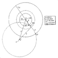
Fig. 5 A and Fig. 5 B show the identical servo patterns according to the front surface of an embodiment of dish of the present invention (Fig. 5 A) and rear surface (Fig. 5 B).
Fig. 6 is the explanation that exemplary disc drives geometry.
Fig. 7 is for the panel surface with linear servo sector, as the function of radius with respect at inside radius (r
ID) the figure that adjusts of 0 timing of regularly adjusting.
Fig. 8 be have in fact symmetry servo field, according to the view of servo sector part of the present invention.
Fig. 9 be have the servo-drive system (being also referred to as time-based servo-drive system) that is used for based on phase place the servo field with symmetry in fact, according to the view of servo sector part of the present invention.
Embodiment
Fig. 1 illustrate and have revolving actuator 2 and rigidity magnetic recording disk 10 (have first or " preceding " surface 11 on the servo sector of patterning in advance 18 that forms) disk drive.Dish 10 rotates with direction 102 about central shaft 100.Front surface 11 has the annular data tape 12 that is limited by internal diameter (ID) 14 and external diameter (OD) 16.Data tape between the servo sector 18 partly is used for the storage of user data and comprises the circular data magnetic track, generally each data track is divided into the physical data sector.Revolving actuator 2 is about fulcrum 4 rotations and at its end support W head 6.When the rotation of actuator 2, magnetic head 6 is along the cardinal principle bow-shaped route between ID14 and the OD16.
Servo sector 18 is not that servo the writing (servowriting) by routine forms, but is formed by the patterned process of utilizing master module.In contact crosstalk technology (CMT) (being also referred to as the stamp of magnetic lithographic plate), magnetic masks (mask) is as master module.In the ultra micro stamp, master module copies to topological pattern on the polymer protective layer that is coated on the dish substrate, then is the sputter precipitation of the magnetic material on pattern.Servo sector 18 forms the pattern with the arcuate line of angle intervals that radially extends substantially from ID14 to OD16.The bow-shaped route of the bowed shape of servo sector and magnetic head 6 is complementary.In the operating period of disk drive, magnetic head 6 a plurality of in annular data tape 12 ID 14 and the circular concentric data track between the OD 16 in read or write data on selected one.In order accurately to read or write data, require magnetic head 6 to remain on the center line of magnetic track from selected magnetic track.Therefore, in the time of under one of servo sector 18 process magnetic head 6, (position error signal PES) detects discrete magnetization servo block to the position error signal of magnetic head 6 in servo sector in the field.The head position control system that produces PES and disk drive uses PES that magnetic head 6 is moved to track centreline.Therefore, during a complete rotation of dish 10,, magnetic head 6 is remained on the track centreline continuously by from continuous servo-information with servo block in the servo sector 18 of angle intervals.
The amplification plan view of typical servo sector 18 and three data track portions has been shown among Fig. 2.Briefly show three data magnetic tracks 20,22,24.As fruit tray 10 are the types that have the successive layers of magnetic recording material in the data division on surface 11, and then magnetic track the 20,22, the 24th, continuous magnetic track, and when magnetic head 6 write down on continuous recording layer, the radial width of this continuous magnetic track was generally limited by magnetic head 6.As fruit tray 10 are the types that have discrete track, and then magnetic track 20,22,24 will comprise the continuous recording material along magnetic track, and described magnetic track will be separated from one another by non magnetic boundary belt.As fruit tray 10 are the types that have patterned medium, and then magnetic track 20,22,24 will all comprise the discrete island of magnetisable material.
Institute's shaded portion of Fig. 2 is represented with the magnetized discrete servo block of equidirectional.If disk drive is designed for warp-wise or horizontal magnetic recording, then they can flatly magnetize with identical direction, promptly in Fig. 2, be parallel in the plane of paper plane, if perhaps disk drive is used for the vertical magnetism record, then they can vertically magnetize with identical direction, promptly enter or leave paper plane.Every other shadow region among Fig. 2 also may have opposite polarity, non-hatched area is non magnetic, this has improved the signal quality of servo pattern, as is disclosed as US20060279871A1 and transfers the assignee's identical with the application application 11/149,028 described.If servo sector 18 is formed by CMT, then the non-shaded portion of Fig. 2 is represented with the direction magnetized zone opposite with the direction of magnetization of servo block, and this is to keep this opposing magnetization because they are handled from the DC magnetization of handling prior to CMT.If form servo sector 18 by ultra micro stamp, then the non-shaded portion of Fig. 2 is represented the unmagnetized zone, i.e. the zone of unmagnetized material or generally can not be by the zone of the magnetized magnetic material of write head.
As shown in Figure 2, the servo block of forming servo sector 18 is arranged in field 30,40,50 and 60.Servo field 30 is automatic gain control (AGC) fields of piece 31-35, the gain that piece 31-35 is used for the amplitude of measuring-signal and is provided for the servo block adjustment of next being read.Servo field 40 is sector mark (SID) fields, is also referred to as servo fixed timing mark or STM field, sets up so that fixed timing mark to be provided so that for ensuing servo block to begin/stop timing window.Servo field 50 is magnetic track signs (TID), is also referred to as cylinder (cylinder) or CYL field, and this is the magnetic track formation cylinder magnetic track because of all panel surface in the disk drive that carries a plurality of dishes that pile up.TID field 50 comprises track number, generally is Gray code, and the integral part of definite radial position.Servo field 60 is position error signal (PES) fields, comprises A, B, C, the D son field of servo block in this example, as the part of known " four train of impulses (quad-burst) " PES pattern, and is used for determining the fraction part of radial position.
Fig. 3 is the block diagram of disk drive servo-control system, and illustrates read/write electronic equipment 210, servo electronics 220, interface electronics 230 and controller electronic equipment 240.Read/write electronic equipment 210 will be delivered to servo electronics 220 from the servo-information of servo sector from magnetic head 6 received signals, and data-signal is delivered to controller electronic equipment 240.Servo electronics 220 uses servo-information to produce the signal at 221 places of driving actuator 2 positioning heads 6.Interface electronics 230 communicates by interface 231 and host computer system (not shown), Data transmission and command information, comprise from host computer system, be used for from the request of coiling that 10 data sector is read or writing to the data sector of dish 10.Interface electronics 230 communicates by interface 233 and controller electronic equipment 240.
Controller electronic equipment 240 comprises microprocessor 241 and has being used to of being stored carries out the storer that is associated 242 of the computer program of various algorithms (comprising control algolithm).Control algolithm is used and to be stored in the storer 242 and based on the static state of actuator 2 and one group of parameter of dynamic perfromance.Control algolithm comes down to the matrix multiple algorithm, and parameter is a coefficient used in multiplying each other.
Controller electronic equipment 240 receives the data sector that row are asked from interface electronics 230, and converting them to cylinder (cylinder) (being magnetic track), magnetic head and data sector number, they are the physical location of desired data sector on the sign dish 10 uniquely.Magnetic head and cylinder number are delivered to servo electronics 220, and servo electronics 220 is positioned at magnetic head 6 on the suitable data sector on the suitable cylinder.If it is different with the cylinder number that current magnetic head 6 is positioned to be provided to the cylinder number of servo electronics 220, then servo electronics 220 is at first carried out " tracking " operation so that magnetic head 6 is moved to desired cylinder from its current track cylinder.
Servo electronics 220 at first begins to carry out the sector computing, so that locate and identify desired data sector.Along with servo sector process under magnetic head 6, detect each servo sector.In simple terms, use SID location servo sector, and come the SID counting of the servo sector of self-contained index marker (index mark) to identify each servo sector uniquely.SID demoder 400 receives the control input 430 of self-controller electronic equipment 240, and this control input 430 is opened time window for the detection of next SID.Then, SID demoder 400 receives data stream regularly 211 as the input from read/write electronic equipment 210.In case detected SID, then produced SID and find signal.Use SID discovery signal 420 to adjust timing circuit 401, the sequence of operation of the remainder (remainder) of timing circuit 401 control servo sectors.After the detection of SID, magnetic track sign (TID) demoder 402 receives timing information 422 from timing circuit 401, reads the signal by TID field 50 (Fig. 2) generation, then the TID information 424 through decoding is delivered to controller electronic equipment 240.During search operation, controller electronic equipment 240 use TID information estimate the position and the speed of magnetic head from the stored programme of the instruction that is expressed as position and speed estimator 245.
In case servo electronics 220 is positioned at magnetic head 6 on the suitable cylinder, then read servo field and read/write electronic equipment 210 is input to servo electronics 220 with signal 211 by magnetic head 6.Then, PES demoder 403 is caught the signal from PES field 60 (Fig. 2), then PES 426 is delivered to controller electronic equipment 240.Controller electronic equipment 240 uses PES as the input to control algolithm, calculates the signal 428 of actuator position controller 404, so that magnetic head 6 is remained on the center line of desired magnetic track.
Referring again to Fig. 1, servo sector 18 is shaped as arcly as can be seen, and its rotation center is the fulcrum 4 of actuator 2.The bowed shape of servo sector has guaranteed being maintained fixed through the time interval between the continuous servo sector of magnetic head, no matter and which magnetic track magnetic head is positioned at.Because obtained constant servo sample rate, no matter and the motion of magnetic head, so this has simplified the design and the operation of head position servo-drive system.
Yet, this requirement of the shape of servo sector is meaned that second or " back " surface of each dish must be first or the mirror image of front surface.This has also guaranteed by the order of the detected servo field of magnetic head (Fig. 2) identical for each panel surface, so that do not need the modification of servo-control system.Fig. 4 A and Fig. 4 B show when dish rotates with direction 102, the comparison of front surface 11 of prior art dish (Fig. 4 A) and rear surface 11a (Fig. 4 B).The bending direction of arc servo sector 18 (Fig. 4 A) is not identical with two servo patterns that comparison shows that of the bending direction of arc servo sector 18a (Fig. 4 B), but mirror image each other.Therefore being used for servo sector 18a must be the mirror image that is used for servo sector 18 is formed the master module of pattern on front surface 11 at the master module that forms pattern on the 11a of rear surface.Yet this requires to make two different master modules, and uses it to form the servo pattern of single disc.
In the present invention, single master module is used for two panel surface, makes front surface and rear surface have identical servo pattern.Fig. 5 A shows according to the front surface 511 (Fig. 5 A) of an embodiment of dish 510 of the present invention and the identical servo pattern of rear surface 511a (Fig. 5 B) with Fig. 5 B.The bending direction of the bending direction of arc servo sector 518 (Fig. 5 A) and arc servo sector 518a (Fig. 5 B) comparison shows that two servo patterns are identical.Yet clearly, the servo sector 518a on the 511a of rear surface does not have the arc shape along actuator 2, makes to obtain constant servo sample rate on surperficial 511a.In addition because surface 511 is identical with servo pattern on the 511a, so on the 511a of rear surface by the order of the detected servo field of magnetic head 6a will with front surface 511 on by the reversed in order of magnetic head 6 detected servo fields.Therefore, in the present invention, the operation of the servo-control system in the servo sector and/or the layout of field have been revised.
In the present invention, make the timing adjustment of the detection that is used for servo sector, so that adapt to the pattern of (accommodate) rear surface 511.This makes an explanation Fig. 6 that use shows the typical disk drive geometry.Actuator between fulcrum 4 and disk center's axle 100 apart from the p place, and have actuator length a, a is the distance from fulcrum 4 to the actuator top RW that magnetic head was positioned at.Magnetic head on the actuator top is made from dish internal diameter r
IDSome b1 to dish external diameter r
ODSome b2 pass the arc of dish or path Z1.In this case, with front surface 511 on those similar conventional servo sectors 518 will have the curvature that radius is a.From Fig. 6, directly conclude, provide by following as " tilting (skew) " angle of the function of radius:
Because magnetic head is fixed on the top of actuator, thus the magnetic transition of writing by magnetic head (transition) not with radius at straight line (or not vertical) with track direction.This is so-called magnetic head " inclination ".Tilt to provide from triangle (4-100-RW) magnetic head by following:
When comparing, the time delay of actuator sector is provided by following with linear sector (draw a straight line to b2 from b1 and produce):
Wherein angle [alpha] is shown with kilsyth basalt.In Fig. 7, draw this and regularly adjust, with respect to the r that is assumed to 0 as the function of radius
IDThe timing adjustment at place.At rpm be in 15,000 the dish, based on Fig. 6 in listed dimension produce Fig. 7.
Therefore, as shown in Figures 5A-5B in the first embodiment of the present invention, when servo-control system is operated on front surface 511, do not need regularly to adjust.Yet, when servo-control system is operated, introduced twice regularly adjustment shown in Figure 7 on the 511a of rear surface.Shown in Figure 3 for the modification that adapts to the servo-control system that the incorrect timing that causes owing to the pattern on the 511a of rear surface carries out, as regularly adjusting controller 250, it generally is the computer program instructions that is stored in the storer 242.During search operation, the timing adjustment between the continuous servo sector is because the radial position of magnetic head changes and changes.Controller equiment 240 uses to calculate regularly from the estimated head position that goes out of estimator 245 and speed and adjusts.Use the radius (being cylinder) that magnetic head was positioned at,, calculate regularly from look-up table or the formula that from the data of Fig. 7, produces and to adjust promptly from the estimated head position that goes out of estimator 245.Controller electronic equipment 240 uses this timing adjustment that calculates to trigger SID demoder 400 then, is used for the timing window that SID detects so that open.
In a second embodiment, servo sector generally is the straight line (between the b1 and b2 in Fig. 6) of radial direction.Similar with first embodiment, front surface is identical with servo pattern on the rear surface.Yet, in this embodiment, when servo-control system is operated, introduced the timing adjustment shown in Fig. 7 on each surface.For example, with reference to Fig. 7, if from radius 20mm (with respect to r
IDThe timing adjustment be 15 μ s) require search to radius 26mm (regularly adjust=30 μ s), then introduce the delay of 15 μ s (30 μ s-15 μ s).
In the present invention, be used for the requirement that servo sector regularly adjusts because front surface has identical pattern with rear surface 511,511a, so on the surperficial 511a by the order of the detected servo field of magnetic head will with the reversed in order on surface 511.Exist several modifications of servo-control system to adapt to this problem.In one embodiment, not to the modification of servo field, but with the servo sector on the opposite sequential read rear surface 511a, i.e. PES, CYL, SID, AGC, and it is stored in the storer.After reading AGC and being translated into the servosignal amplitude, analyze SID and set up timing.Even with desired comparing, the SID mark is that the time is opposite, still can use the identical association process that is used for front surface 511, unless there is the adaptation of the position order that is used to reverse.After setting up regularly, decoding CYL value (considering the position order of counter-rotating once more), and decoding PES.In this embodiment, have the time delay on the corresponding rear surface 511a of length of general and a servo sector, this is because before carrying out any computing by controller electronic equipment 240, reads servo sector and it is stored in the storer.
In another embodiment, use to have the servo sector of the servo field of symmetry in fact, as shown in Figure 8.In the embodiment of Fig. 8, for front surface and rear surface, the order that reads servo field is identical.For example, for the front surface shown in Fig. 5 A 511, servo field will move with the direction shown in the arrow 102, and for the rear surface 511a shown in Fig. 5 B, servo field will move with the direction shown in the arrow 102a.Servo field is symmetrical in fact about the center of servo sector.The PES field is positioned at the center of servo sector, and the CYL sign indicating number is distributed in the end opposite of PES field as CYL1 and CYL2.Complete CYL field generally includes the m position, and it comprises actual magnetic track information and n error correcting code (ECC) position, and wherein general m and n have similar value.For the symmetrical form of Fig. 8, the CYL field is divided into two son fields (CYL1 and CYL2).CYL1 and CYL2 all can provide part (partial) information about cylinder number, yet also need both to obtain to relate to the accurate track number of ECC.For example, each CYL1 and CYL2 all can have the m+n/2 position.This allows to be used for the enough information of long search.Identical AGC field (AGC1 and AGC2) is positioned at each end of servo sector, and identical SID field (SID1 and SID2) is between corresponding AGC and CYL field.In the servo sector form shown in Fig. 8, additional panel surface " expense (overhead) " is used for the extra m position of the 2nd SID field and the 2nd CYL field.In typical servo-drive system, for example 140 servo sectors center on panel surface angularly at interval, and this will cause being used to have about 16 expenses and the about 12-16 position that is used for the 2nd SID field of two CYL fields (supposition does not have ECC).Typical servo sector can have about 40 AGC, 12 SID, 32 bit track sign indicating numbers, 12 sector code and 48 PES sign indicating numbers, about altogether 144.Therefore, Fu Jia 28-32 position is 20% increment in the servo expense on the conventional servo pattern (Fig. 2) approximately.
Another embodiment with servo sector of symmetrical in fact servo field uses the servo-drive system (being also referred to as time-based servo-drive system) based on phase place, and its pattern as shown in Figure 9.PES field 700 comprises two symmetric sets 702,704 of the cardinal principle obliquity mark that radially passes a plurality of magnetic tracks substantially and extend.(start-of-field, SOF) mark 701,703 is positioned at the respective end of PES field 700 to the beginning of identical field, and radially passes magnetic track and extend.Radial position from the time indication magnetic head of the detection that detects the obliquity mark of SOF mark.Such PES field is different from the routine four burst PES fields 60 among Fig. 2, and therefore uses dissimilar PES decode systems.Servo-drive system and coding/decoding method based on phase place are known, for example, as United States Patent (USP) 5,689,384,5,923,272,5,930,065 is described.In the embodiment of Fig. 9, the CYL field can be encoded to be positioned at the additional pattern that collected before or after 702,704.Selectively, can be in the collection 702,704 of the position mark that tilts by move (shift) with respect to other position marks morning in the pattern or late position mark to, with the mode of the total phase relation CYL field of encoding between the impact position mark not.Have based on the example of this coding of timing pattern and in the United States Patent (USP) of quoting before 5,923,272 and 5,930,065, describe.Because this method of coding CYL field only is embedded in single position or small number of bits at each servo sector, so the complete servo sector that needs several successive that reads of complete CYL address.
Though, illustrated and described the present invention especially with reference to preferred embodiment, it will be apparent to one skilled in the art that under the premise without departing from the spirit and scope of the present invention, can make in form and the various changes on the details.Therefore, only regard disclosed invention as exemplary, and only limit by the scope of appointment in the claims.
Claims (20)
1. magnetic recording disk, have first substantially plane surface, the second cardinal principle plane surface relative with this first surface and with the central shaft of described Surface Vertical, this dish comprises:
Be positioned at a plurality of servo sectors of this first surface, form about the linear pattern of described axle with angle intervals, and extending in the radial direction substantially, each servo sector comprises a plurality of discrete areas of magnetic material; And
Be positioned at a plurality of servo sectors of this second surface, form with described first surface on the identical pattern of pattern.
2. dish according to claim 1, wherein each the bar line in each described lip-deep described servo pattern all is to be the arcuate line of extending between the interior and cylindrical at center with described axle radially substantially.
3. dish according to claim 1, wherein each the bar line in each described lip-deep described servo pattern all is to be the radial alignment of extending between the interior and cylindrical at center with described axle radially substantially.
4. dish according to claim 1, wherein each described surface includes continuous magnetic material layer, and described discrete area comprise described magnetic material through magnetized block.
5. dish according to claim 1, wherein to include with described axle be the concentric circles data track of a plurality of magnetisable materials at center and the boundary belt of non-magnetisable material on each described surface, wherein the data track of radially adjoining is separated by boundary belt.
6. dish according to claim 1, wherein each described surface includes a plurality of concentric circles data tracks on the discrete data island of magnetisable material.
7. dish according to claim 1, wherein arrange this discrete area in each servo sector in the field of angle intervals, this field comprises automatic gain control (AGC) field, sector mark (SID) field, magnetic track identification field (TID) and servo position error signal (PES) field.
8. dish according to claim 1 is wherein arranged this discrete area in each servo sector in the field of angle intervals, described field cardinal principle is about the center symmetry of this servo sector.
9. dish according to claim 8, wherein said with in the field of angle intervals first is automatic gain control (AGC) field, second in the described field is sector mark (SID) field, the penult of described field is similar SID field, and last of described field is similar AGC field.
10. dish according to claim 1, wherein this discrete area in each servo sector is magnetized to the surface that is parallel to them and forms substantially thereon.
11. dish according to claim 1, wherein this discrete area in each servo sector is magnetized to the surface that forms perpendicular to them substantially thereon.
12. a magnetic recording disk, have first substantially plane surface, the second cardinal principle plane surface relative with this first surface and with the central shaft of described Surface Vertical, this dish comprises:
A plurality of cardinal principle circular concentric data tracks of each described lip-deep magnetic material, this data track is the center with described axle;
Be positioned at a plurality of servo sectors of this first surface, formation is about the linear pattern of described axle with interval, angle ground, and extend in the radial direction in the cardinal principle of passing described data track, each servo sector comprises a plurality of discrete areas of magnetic material, this piece is arranged in along data track in the field with angle intervals, and described field is substantially about the center symmetry of this servo sector; And
Be positioned at a plurality of servo sectors of this second surface, form with described first surface on the identical pattern of pattern.
13. dish according to claim 12, wherein each the bar line in each described lip-deep described servo pattern all is to be the arcuate line of extending between the interior and cylindrical at center with described axle radially substantially.
14. dish according to claim 12, wherein each the bar line in each described lip-deep described servo pattern all is to be the radial alignment of extending between the interior and cylindrical at center with described axle radially substantially.
15. dish according to claim 12, wherein each described discrete area include described magnetic material through magnetized block.
16. dish according to claim 12, wherein the data track of radially adjoining is separated by the boundary belt of non-magnetisable material.
17. dish according to claim 12, wherein arrange the discrete area in each servo sector in the field of angle intervals, this field comprises automatic gain control (AGC) field, sector mark (SID) field, magnetic track identification field (TID) and servo position error signal (PES) field.
18. a magnetic recording disk drive comprises:
Rotatable magnetic recording disk, before having substantially plane surface, the back cardinal principle plane surface relative with this front surface and with the rotary middle spindle of described Surface Vertical, this dish comprises: (a) a plurality of cardinal principle concentric circles data tracks of each described lip-deep magnetic material, and this data track is the center with described axle; (b) be positioned at a plurality of servo sectors on the front surface, formation is about the linear pattern of described axle with angle intervals, and extend in the radial direction in the cardinal principle of passing described data track, each servo sector comprises a plurality of discrete areas of magnetic material, this piece is arranged in along this data track in the field with angle intervals, and one of described field is position error signal (PES) field; And (c) be positioned at a plurality of servo sectors on the rear surface, form with described front surface on the identical pattern of pattern;
First magnetic head detects the servo sector on this front surface;
Second magnetic head detects the servo sector on this rear surface;
With the actuator that this magnetic head is connected, be used for this head position is also remained on this data track with this magnetic head to different data tracks;
Servo-control system, with this magnetic head and the coupling of this actuator, this servo-control system comprises processor, is used for allowing during the time window of appointment the detection of PES field, and is used for the detection generation actuator control signal in response to the PES field of this magnetic head; And
Storer, with this processor coupling, and comprise by the readable instruction repertorie of this processor, this instruction repertorie carries out the action of such method, comprising: estimate the radial position of this magnetic head, adjust and use the time that is calculated to adjust this time window from the estimated position calculation time that goes out.
19. disk drive according to claim 18, wherein each the bar line in each described lip-deep described servo pattern all is to be the arcuate line of extending between the interior and cylindrical at center with described axle radially substantially; And wherein the action of adjusting computing time comprises the action that only adjust computing time when detecting this PES field by described second magnetic head.
20. disk drive according to claim 18, wherein each bar line of each described lip-deep described servo pattern all is to be the radial alignment of extending between the interior and cylindrical at center with described axle radially substantially, and the action of wherein adjusting computing time that action comprises when detecting this PES field by described first magnetic head and adjust computing time when detecting this PES field by described second magnetic head.
Applications Claiming Priority (2)
| Application Number | Priority Date | Filing Date | Title |
|---|---|---|---|
| US11/740,289 | 2007-04-26 | ||
| US11/740,289 US7652839B2 (en) | 2007-04-26 | 2007-04-26 | Magnetic recording disk with identical servo patterns formed on each disk surface by single master template and disk drive using the disk |
Publications (1)
| Publication Number | Publication Date |
|---|---|
| CN101295515A true CN101295515A (en) | 2008-10-29 |
Family
ID=39671387
Family Applications (1)
| Application Number | Title | Priority Date | Filing Date |
|---|---|---|---|
| CNA2008100820715A Pending CN101295515A (en) | 2007-04-26 | 2008-03-06 | Magnetic recording disk with identical servo patterns formed on each disk surface by single master template and disk drive using the disk |
Country Status (9)
| Country | Link |
|---|---|
| US (1) | US7652839B2 (en) |
| EP (1) | EP1986185A1 (en) |
| JP (1) | JP5049177B2 (en) |
| KR (1) | KR20080096386A (en) |
| CN (1) | CN101295515A (en) |
| BR (1) | BRPI0803930A2 (en) |
| RU (1) | RU2008116550A (en) |
| SG (1) | SG147365A1 (en) |
| TW (1) | TW200849225A (en) |
Families Citing this family (17)
| Publication number | Priority date | Publication date | Assignee | Title |
|---|---|---|---|---|
| JP4489031B2 (en) * | 2006-02-17 | 2010-06-23 | 東芝ストレージデバイス株式会社 | Disk device correction system, information management device, master production device, and master production method |
| US7848040B2 (en) * | 2007-08-17 | 2010-12-07 | Hitachi Global Storage Technologies Netherlands B.V. | Magnetic recording disk and disk drive with amplitude-type servo fields having patterned alternating-polarity servo islands for read/write head positioning |
| US8422169B2 (en) | 2009-12-14 | 2013-04-16 | Seagate Technology Llc | Shallow trench discrete track media (DTM) and pattern transfer process |
| US9384779B2 (en) | 2009-12-18 | 2016-07-05 | HGST Netherlands B.V. | Information storage device with multiple-use fields in servo pattern |
| US9311942B2 (en) * | 2009-12-18 | 2016-04-12 | HGST Netherlands B.V. | Information storage device with multiple-use fields in servo pattern |
| US8422161B2 (en) * | 2009-12-18 | 2013-04-16 | HGST Netherlands B.V. | Information storage device with multiple-use fields in servo pattern |
| JP2011165300A (en) * | 2010-01-12 | 2011-08-25 | Fujifilm Corp | Magnetic recording medium, magnetic recording apparatus equipped with the magnetic recording medium, and transfer master carrier |
| JP5553621B2 (en) * | 2010-01-25 | 2014-07-16 | サムスン電機ジャパンアドバンスドテクノロジー株式会社 | Disk drive |
| US8477442B2 (en) | 2010-05-11 | 2013-07-02 | HGST Netherlands B.V. | Patterned media for self-servowriting integrated servo fields |
| US8335047B2 (en) | 2010-10-07 | 2012-12-18 | HGST Netherlands B.V. | Patterned media with offset PES servo segments with length encoded track position |
| US8363348B2 (en) | 2010-10-07 | 2013-01-29 | HGST Netherlands B.V. | Patterned media with structured PES servo segments encoding local track position |
| US8743496B2 (en) | 2011-07-06 | 2014-06-03 | HGST Netherlands B.V. | Servo pattern compatible with planarization constraints of patterned media and use of a single master template |
| US8531794B2 (en) | 2011-07-06 | 2013-09-10 | HGST Netherlands, B.V. | Patterned media with an alternating series of concentric servo zones and overlap zones |
| US8619379B2 (en) | 2011-07-06 | 2013-12-31 | HGST Netherlands B.V. | Patterned media with an alternating series of concentric servo zones and overlap zones |
| US8625219B2 (en) | 2011-07-06 | 2014-01-07 | HGST Netherlands B.V. | Patterned media with an alternating series of concentric servo zones and overlap zones |
| US8670207B2 (en) | 2011-07-06 | 2014-03-11 | HGST Netherlands B.V. | Servo pattern compatible with planarization constraints of patterned media and use of a single master template |
| US8630051B2 (en) | 2011-07-06 | 2014-01-14 | HGST Netherlands B.V. | Patterned media with an alternating series of concentric servo zones and overlap zones |
Family Cites Families (23)
| Publication number | Priority date | Publication date | Assignee | Title |
|---|---|---|---|---|
| US4912585A (en) | 1988-04-28 | 1990-03-27 | International Business Machines Corporation | Discrete track thin film magnetic recording disk with embedded servo information |
| JP3344495B2 (en) | 1993-03-04 | 2002-11-11 | ソニー株式会社 | Magnetic disk drive |
| US5689384A (en) | 1994-06-30 | 1997-11-18 | International Business Machines Corporation | Timing based servo system for magnetic tape systems |
| TW342495B (en) | 1996-07-22 | 1998-10-11 | Matsushita Electric Ind Co Ltd | Master information carrier, method of producing the same, and method for recording master information signal on magnetic recording medium |
| JPH1050013A (en) | 1996-08-02 | 1998-02-20 | Fujitsu Ltd | Off-track correcting method for disk device |
| US5930065A (en) | 1997-05-16 | 1999-07-27 | International Business Machines Corporation | Timing based servo longitudinal addressing |
| US5923272A (en) | 1997-07-08 | 1999-07-13 | International Business Machines Corporation | Serial bitstream code for timing-based servo |
| US6018512A (en) * | 1997-11-18 | 2000-01-25 | Seagate Technology, Inc. | System and method of encoding for identifying a given surface among several identically patterned disk surfaces |
| US6433944B1 (en) | 1998-09-25 | 2002-08-13 | Fuji Photo Film Co., Ltd. | Master carrier for magnetic transfer and method for transfer |
| US6538835B1 (en) | 1999-02-22 | 2003-03-25 | Seagate Technology Llc | Position signal distortion compensation during a disc drive seek |
| US6754032B1 (en) | 1999-10-22 | 2004-06-22 | Seagate Tech. Llc | Method and system for radial and circumferential alignment of data tracks on patterned media |
| JP2003007011A (en) * | 2001-06-21 | 2003-01-10 | Hitachi Ltd | Magnetic disk device |
| US6798590B2 (en) | 2002-01-22 | 2004-09-28 | Hitachi Global Storage Technologies Netherlands B.V. | Method for contact magnetic transfer of servo pattern to hard magnetic recording disk |
| US7027246B2 (en) * | 2002-05-09 | 2006-04-11 | Maxtor Corporation | Method for servo pattern application on single-side processed disks in a merged state |
| JP2004213700A (en) | 2002-11-15 | 2004-07-29 | Fuji Electric Device Technology Co Ltd | Master disk for magnetic recording medium, and positioning device and method |
| US7511912B2 (en) * | 2002-11-22 | 2009-03-31 | Seagate Technology Llc | Writing multiple servo sector patterns to improve servo sector alignment on multiple surfaces |
| US6791774B1 (en) | 2003-05-12 | 2004-09-14 | Hitachi Global Storage Technologies Netherlands B.V. | Contact magnetic transfer of servo pattern to rigid perpendicular magnetic recording disk |
| US7092183B2 (en) | 2003-12-10 | 2006-08-15 | Matsushita Electric Industrial Co., Ltd. | Template pattern for improving printed media self-servo writing |
| JP2006031856A (en) * | 2004-07-16 | 2006-02-02 | Toshiba Corp | Patterned disk medium for vertical magnetic recording, and magnetic disk drive mounting medium thereon |
| JP2006031848A (en) | 2004-07-16 | 2006-02-02 | Toshiba Corp | Magnetic disk and magnetic disk device equipped with the same |
| US7046476B1 (en) | 2005-01-10 | 2006-05-16 | Hitachi Global Storage Technologies | Method apparatus and system for accessing discontinuous media tracks |
| JP2006318581A (en) * | 2005-05-13 | 2006-11-24 | Tdk Corp | Information recording medium, recording/reproducing device, and stamper |
| US7236325B2 (en) | 2005-06-09 | 2007-06-26 | Hitachi Global Storage Technologies Netherlands B.V. | Method for formatting a magnetic recording disk with patterned nondata islands of alternating polarity |
-
2007
- 2007-04-26 US US11/740,289 patent/US7652839B2/en not_active Expired - Fee Related
-
2008
- 2008-02-14 TW TW097105224A patent/TW200849225A/en unknown
- 2008-02-22 EP EP08250621A patent/EP1986185A1/en not_active Ceased
- 2008-03-06 SG SG200801864-0A patent/SG147365A1/en unknown
- 2008-03-06 CN CNA2008100820715A patent/CN101295515A/en active Pending
- 2008-03-28 JP JP2008087303A patent/JP5049177B2/en not_active Expired - Fee Related
- 2008-04-07 KR KR1020080032212A patent/KR20080096386A/en not_active Application Discontinuation
- 2008-04-25 RU RU2008116550/28A patent/RU2008116550A/en not_active Application Discontinuation
- 2008-04-28 BR BRPI0803930-5A patent/BRPI0803930A2/en not_active IP Right Cessation
Also Published As
| Publication number | Publication date |
|---|---|
| BRPI0803930A2 (en) | 2009-06-02 |
| KR20080096386A (en) | 2008-10-30 |
| EP1986185A1 (en) | 2008-10-29 |
| JP5049177B2 (en) | 2012-10-17 |
| JP2008276911A (en) | 2008-11-13 |
| SG147365A1 (en) | 2008-11-28 |
| TW200849225A (en) | 2008-12-16 |
| US20080266701A1 (en) | 2008-10-30 |
| RU2008116550A (en) | 2009-10-27 |
| US7652839B2 (en) | 2010-01-26 |
Similar Documents
| Publication | Publication Date | Title |
|---|---|---|
| CN101295515A (en) | Magnetic recording disk with identical servo patterns formed on each disk surface by single master template and disk drive using the disk | |
| CN101329874B (en) | Magnetic recording disk drive with head positioning servo control system for disk surfaces with identical servo patterns | |
| US6490111B1 (en) | Method and apparatus for refreshing servo patterns in a disc drive | |
| US6781778B1 (en) | Time-based sectored servo data format | |
| US6643082B1 (en) | Servo sector format for a patterned media | |
| US7948701B2 (en) | Servo patterns for self-assembled island arrays | |
| US7911728B2 (en) | Method for servowriting a patterned-media perpendicular magnetic recording disk using position error signal (PES) alignment fields | |
| US8848310B2 (en) | Offset correction values on a data storage media | |
| US8477442B2 (en) | Patterned media for self-servowriting integrated servo fields | |
| KR100528250B1 (en) | Apparatus for developing a dynamic servo signal from data in a magnetic disc drive and method | |
| US8335047B2 (en) | Patterned media with offset PES servo segments with length encoded track position | |
| US7848047B2 (en) | Patterned media magnetic recording disk drive with write clock phase adjustment for data pattern circumferential misalignment | |
| JPH02146153A (en) | Magnetic recording disc | |
| US8427772B2 (en) | Patterned-media magnetic recording disk drive with data island misplacement information in the servo sectors | |
| US20100067142A1 (en) | Phase Servo Patterns for Bit Patterned Media | |
| EP2026336A1 (en) | Magnetic recording disk and disk drive with patterned phase-type servo fields for read/write head positioning | |
| US7036209B1 (en) | Method of simultaneously forming magnetic transition patterns of a dual side recording medium | |
| US7218466B1 (en) | Contact printing of magnetic media with mechanically reinforced and/or gas venting stamper | |
| US8665549B2 (en) | Method for creating burst magnitude servo patterns with unipolar bits on a magnetic media of a magnetic data recording system | |
| US7630156B2 (en) | Magnetic recording medium, recording/reproducing apparatus, and stamper for manufacturing a magnetic recording medium | |
| GB2279491A (en) | A magnetic disk drive | |
| US20160111119A1 (en) | Integrated servo field for memory device | |
| US7359133B2 (en) | Magnetic recording medium and drive apparatus therefor | |
| JP2002015418A (en) | Magnetic disk and method for manufacturing magnetic disk |
Legal Events
| Date | Code | Title | Description |
|---|---|---|---|
| C06 | Publication | ||
| PB01 | Publication | ||
| C10 | Entry into substantive examination | ||
| SE01 | Entry into force of request for substantive examination | ||
| C12 | Rejection of a patent application after its publication | ||
| RJ01 | Rejection of invention patent application after publication |
Application publication date: 20081029 |