EP0115699A1 - Methods and apparatus for recording and reproducing analog signals - Google Patents
Methods and apparatus for recording and reproducing analog signals Download PDFInfo
- Publication number
- EP0115699A1 EP0115699A1 EP83307958A EP83307958A EP0115699A1 EP 0115699 A1 EP0115699 A1 EP 0115699A1 EP 83307958 A EP83307958 A EP 83307958A EP 83307958 A EP83307958 A EP 83307958A EP 0115699 A1 EP0115699 A1 EP 0115699A1
- Authority
- EP
- European Patent Office
- Prior art keywords
- heads
- signal
- magnetic
- rotary
- time
- Prior art date
- Legal status (The legal status is an assumption and is not a legal conclusion. Google has not performed a legal analysis and makes no representation as to the accuracy of the status listed.)
- Granted
Links
Images


Classifications
-
- G—PHYSICS
- G11—INFORMATION STORAGE
- G11B—INFORMATION STORAGE BASED ON RELATIVE MOVEMENT BETWEEN RECORD CARRIER AND TRANSDUCER
- G11B20/00—Signal processing not specific to the method of recording or reproducing; Circuits therefor
- G11B20/10—Digital recording or reproducing
- G11B20/10527—Audio or video recording; Data buffering arrangements
-
- G—PHYSICS
- G11—INFORMATION STORAGE
- G11B—INFORMATION STORAGE BASED ON RELATIVE MOVEMENT BETWEEN RECORD CARRIER AND TRANSDUCER
- G11B20/00—Signal processing not specific to the method of recording or reproducing; Circuits therefor
- G11B20/00007—Time or data compression or expansion
-
- G—PHYSICS
- G11—INFORMATION STORAGE
- G11B—INFORMATION STORAGE BASED ON RELATIVE MOVEMENT BETWEEN RECORD CARRIER AND TRANSDUCER
- G11B20/00—Signal processing not specific to the method of recording or reproducing; Circuits therefor
- G11B20/10—Digital recording or reproducing
- G11B20/18—Error detection or correction; Testing, e.g. of drop-outs
- G11B20/1806—Pulse code modulation systems for audio signals
- G11B20/1809—Pulse code modulation systems for audio signals by interleaving
Definitions
- This invention relates to methods and apparatus for recording and/or reproducing analog signals, and more particularly, but not exclusively, to methods and apparatus for recording and/or reproducing an analog signal as a pulse code modulated (PCM) signal incorporating error-correcting and parity information in which the time-base is compressed prior to recording and is expanded upon reproduction.
- PCM pulse code modulated
- VTR video tape recorder
- the information signal is recorded by the rotary head on the tape in the form of an analog signal
- the PCM signal is a digital signal
- the time-base thereof can be compressed and/or expanded by the use of one or more digital memory units.
- apparatus for recording an analog signal on a magnetic medium using n rotary recording heads that periodically trace the magnetic medium comprising:
- a method for recording an analog signal on a magnetic medium using n rotary recording heads that periodically trace said magnetic medium comprising the steps of:
- apparatus for reproducing an analog signal which has been recorded as a corresponding digital signal in time-base compressed form in a composite digital signal including parity and error correction data in corresponding tracks on a record medium, the apparatus comprising:
- Figure 1 schematically illustrates a rotary head assembly, as used in an embodiment of the present invention, that includes two magnetic heads lA and 1B mounted on a rotating drum (not shown).
- the heads 1A and 1B when the tape 2 is transported at a predetermined speed in a direction shown generally by an arrow 5T the heads 1A and 1B will trace thereon a plurality of magnetic tracks 4A and 4B, respectively, as represented in Figure 2. These slanted magnetic tracks 4A and 4B are recorded one by one on the tape 2 by the heads 1A and 1B thereby recording the signal in a fashion that will be described below.
- high-density data recording is possible by using different azimuth gap angles in the heads lA and 1B, thereby eliminating the requirement for the so-called guard bands between adjacent tracks. This technique of using different azimuth gap angles relies upon the well-known azimuth loss effect to prevent cross-talk between adjacent tracks.
- the heads lA and 1B are displaced relative to each other in the rotary axial direction, so that the scanning locus by the head 1A is traced by the head 1B in exactly the same way. Note that in the embodiment of Figure 1, there is no free period when the two heads IA and 1B are both out of contact with the tape 2.
- FIG. 3 shows an example of the recording system in which an analog audio signal is recorded as a two channel signal, comprising left and right audio channels.
- a left-channel analog audio signal 5 L is supplied through an input terminal 11L to one input terminal of a switching circuit 12, and a right-channel analog audio signal S R is applied through an input terminal 11R to the other input terminal of the switching circuit 12.
- the switching circuit 12 is changed over alternately in position in response to a switching signal SW, which is a square-wave signal having a duty factor of 50%.
- the switching signal SW is derived from a control signal generator circuit 13 at a frequency of 44.1 kHz and controls the switching circuit 12 so that the switching circuit 12 changes over at each period during which the signal SW is at a high level or at a low level.
- the switching circuit 12 alternately supplies the left channel signal 5 L and the right channel signal S R to an analog-to-digital (A/D) converter 14.
- A/D converter 14 this signal is sampled at a sampling frequency of 44.1 kHz per channel, and then this sampled signal is converted to a pulse code modulation (PCM) signal that in this embodiment may comprise sixteen bits per sample, for example.
- PCM pulse code modulation
- the output signal S 0 from the A/D converter 14 is fed to a recording encoder 15, and the output signal S 0 is shown in the timing charts at Figure 5A.
- the recording encoder 15 is connected to suitable memory circuits, specifically, a random access memory (RAM) 16A is directly connected to an output of the recording encoder 15 and a buffer RAM 16C is connected between an output of the recording encoder 15 and a second random access memory 16B.
- the buffer RAM 16C operates to delay the data input to the RAM 16B to provide the desired time delay.
- a parity word and cyclic redundancy check (CRC) code generating and adding circuit 17.
- a control signal RSW is produced by the control signal generator 13 and fed to the recording encoder 15, which operates in response thereto to switch the PCM data signal S 0 every 1/60 of a second, which corresponds to the duration of time required for one revolution of the heads 1A and 1B.
- the heads 1A and 1B are rotated at a speed that is twice the reference rotation speed of 1/30 of a second.
- the data signal S0 which is switched in the recording encoder 15 in response to the control signal RSW, is then written into the RAMs 16A and 16B as PCM signals S 1 , S 2 , S 3 , . , that have periods of 1/60 of a second and the appropriate parity words and error correcting codes are added thereto, as will be described below.
- the PCM signals S 1 , S 2 , S 3 Vietnamese , which have periods of 1/60 of a second, are separated in the recording encoder 15 so that alternate ones of the signals S 2 , S 4 , S 6 Vietnamese , are written directly into the RAM 16A; the timing of this being shown at Figure 5D.
- the remaining ones of the PCM signals that is S 1 , S 31 S 5 Vietnamese , are fed into the buffer RAM 16C where they are delayed in time by an amount corresponding to one-half a revolution period of the rotary heads IA and 1B, that is, 1/120 of a second, and thereby become signals S 1 ', S 3 ', S 5 ', Across , and are then written into the RAM 16B.
- the timing of the signals into the buffer RAM 16C and the RAM 16B are shown in Figures 5B and 5C, respectively.
- the PCM data having a period of 1/60 of a second is written into the RAMs 16B and 16A, respectively, and during the 1/120 of a second that corresponds to a one-half revolution of the heads lA and 1B following the write periods of the RAMs 16A and 16B, respectively, the parity word and CRC code generating and adding circuit 17 is operated to generate the error correcting parity word and CRC code, which are then added to the data in the recording encoder 15.
- the control signal generating circuit 13 generates the appropriate control signal CP that actuates the CRC adding circuit 17.
- the PCM signals have had the parity and CRC code added thereto they are written back into the RAMs 16A and 16B, respectively, and during the period of 1/120 of a second following the parity word and CRC code generating and adding period, the PCM data in each period of 1/60 of a second are read out from the RAMs 16A and 16B, respectively, at a speed substantially twice that at which they were written in. In other words, the PCM data has been compressed in time-base by one-half and is then made equal to the tape contact period of either the head 1A or the head I B.
- the period during which the PCM data having the compressed time-base is read out from the RAMs 16A and 16B is the period TR during which the signal RSW has a high level
- the waveform of the signal RSW is shown in Figure 5E. Since the signal RSW is inverted in state every 1/60 of a second, which corresponds to one revolution of the heads lA and 1B, the reading out of the data is accomplished at each period representing one revolution.
- the PCM data having the compressed time-base is read out from the RAM 16B
- the PCM data having the compressed time-base is read out from the RAM 16A.
- the data of each unit period having the compressed time-base read from the RAMs 16A and 16B and obtained from the recording encoder 15 is then supplied through a recording amplifier 18 to a respective one of the two heads lA and lB.
- the control signal generating circuit 13 produces a reference signal CT, the waveform of which is shown in Figure 5F, having a frequency of 30 Hz that is fed to a servo circuit 20 so that the heads 1A and 1B are in synchronism with the signals to be recorded.
- a reference signal CT that has a phase different than that of the control signal RSW by ⁇ /2 is fed to the servo circuit 20.
- the feedback to the servo circuit 20 is provided by a pulse generator 21 that generates a pulse signal PG of frequency 30 Hz so that a pulse is present each time the heads 1A and 1B rotate.
- the output from the servo circuit 20 is fed to a head drum drive motor 22 which applies the phase servo to the heads 1A and 1B, so that the head 1A commences contact with the tape 2 at a time corresponding to the occurrence of the trailing edge of the square-wave reference signal CT.
- a first-half rotation period HA in the unit rotational interval P is the period during which the head lA scans the tape 2
- the second-half rotation period HB in the unit rotational interval P is the period in which the head 1B scans the tape 2.
- the read period TB from the RAM 16B corresponds to every other contact period HB of the head 1B with the tape 2
- the read period TA from the RAM 16A corresponds to every other contact period HA of the head lA with the tape 2.
- the second half-period HB in the unit rotational interval P and the first half-period HA in the succeeding unit rotational interval P are coincident with these very same read periods TB and TA, respectively.
- control signal CT produced by the control signal generator 13 is also fed through a recording amplifier 23 to a stationery magnetic head 24, and the time control signal is thereby recorded along an edge of the tape 2 as a control pulse track 6C utilized in the playback mode.
- the control pulse track 6C is seen in relation to the tape 2 in Figure 2.
- the audio PCM signal can be reproduced in the following fashion utilizing apparatus as shown in Figure 4.
- a pulse signal having a frequency of 30 Hz is reproduced from the control pulse track 6C on the tape 2 by the stationary head 24, and this pulse signal is fed to the servo circuit 20 and also to the control signal generator circuit 13.
- the pulse signal PG produced by the pulse generator 21 is also fed to the servo circuit 20, so that the heads 1A and 1B are servo controlled to scan the tracks 4A and 4B, respectively, with the identical relationship as that employed during recording.
- the reproduced signals obtained by the heads 1B and 1A are as represented in Figures 5H and 51.
- the output signals produced by the heads IA and 1B are fed through amplifiers 31A and 31B, respectively, to inputs of a switching circuit 32.
- the switching circuit 32 alternately selects one or the other of the input terminals in response to a switching control signal SH that has a frequency of 30 Hz, the waveform of which is shown in Figure 5G, and which is produced by the control signal generator circuit 13.
- the switching circuit 32 alternately produces a reproduced output from the heads 1A and 1B, respectively, during one rotational period at every other rotation.
- the output signal from the switching circuit 32 is fed to a digital restoring circuit 33 that operates to restore the signal to a digital signal by cleaning and shaping the reproduced waveform, and the restored digital signal is fed to a decoder 34 which it is decoded to the original PCM data signal S0.
- the signal processing is carried out by means of RAMs 35A and 35B, which are changed over in response to a control signal RSWP, the waveform of which is shown in Figure 5M, that is produced by the control signal generator circuit 13.
- the control signal RSWP changes over between a high-level period TWB and a low-level period TWA, and in the first half of the period TWB the output data reproduced by the head 1B is written into the RAM 35B, while in the second half of the period TWB the output data reproduced by the head 1A is delayed by a time of 1/120 of a second by means of the buffer RAM 35C and then subsequently written into the RAM 35A during the first half of the period TWA.
- the PCM data written into the RAMs 35B and 35A are corrected in an error correcting circuit 36 during the second half portions of the 1/120 of a second periods of the periods TWB and TWA, respectively.
- control signal WC supplied to the error corrector circuit 36 from the control signal generator circuit 13 goes high during the second half of the periods TWB and TWA, the error correcting circuit 36 is operated for error correction during those times.
- the waveform of control signal WC is shown in Figure 5N-I. Accordingly, error correction is performed within the error correction ability range by use of the parity word and the CRC code.
- the reproduced data of one track amount that were written in the RAMs 35B and 35A that has been subsequently error corrected are alternately read out at a speed that is approximately one half that used in writing during the periods TWA and TWB, as shown in Figures 5J and 5L, respectively. That is, the PCM signal which now has its time-base expanded to equal the original time-base is successively produced.
- the PCM signal from the decoder unit 34 is fed to an error concealing or error correcting circuit 37, which acts to conceal any errors which could not be corrected by the error correcting circuit 36. This technique is well-known and various value holding systems are known to accomplish error concealment.
- the output signal from the error correcting circuit 37 is fed to a digital-to- analog (D/A) converter 38, wherein it is returned to an analog signal and fed to a switching circuit 39.
- the switching circuit 39 is alternately changed over in response to a switching signal SW, which is identical to the switching signal SW utilized during the recording operation, and the audio signals of the left channel and right channel are thus demodulated and respectively supplied through amplifiers 40L and 40R to output terminals 41 L and 41 R, respectively.
- two rotary heads lA and 1B are located with an angular separation of 180° therebetween and are displaced in the rotational axial direction so that the scanning locus by the head 1A is scanned in exactly the same way by the head 1B
- the embodiment represented in Figure 6 wherein the two rotary heads 1A and 1B are not displaced in the rotational axial direction but are disposed at positions having substantially the same rotational angle.
- the heads 1A and 1B are rotated at a speed which is twice as high as a reference speed, thereby recording the PCM signal as a time-base compressed signal, with the time-base compressed by a factor of one-half.
- the timing of the rotary head system of Figure 6 is shown in Figure 7, wherein the two heads lA and 1B operate to contact simultaneously the tape 2 during only one-half of the revolution period corresponding to the wrap angle of the tape 2 around the periphery of the guide drum 3 and, accordingly, both scan the same scanning locus. More specifically, the heads lA and IB contact the tape 2 at each half revolution of the rotary head assembly, thus, when the heads 1A and 1B are rotated at a speed that is twice as high as a reference speed, the PCM data is respectively recorded by only the head 1A during a certain one-revolution period and only by the head 1B during the successive one-revolution period, as represented by the hatched portions in Figure 7.
- the PCM signal corresponding to the one-revolution period of the heads lA and 1B that is, one-half revolution period amount of the reference speed, namely, the angular spacing amount of 180° that represents the tape wrap angle, can be recorded as each track that has added thereto the error correction parity word and the like and this is compressed in time-base to one-half.
- the rotary heads 1A and IB are mounted with an angular distance of 180° therebetween, however, the wrap angle of the tape about the periphery of the guide drum 3 is much smaller than the head separation angular distance of 180°.
- the tape wrap angle is one half of the head separation angular distance and is 90°, accordingly, the time-base of the recorded signal can be compressed further by an additional half, that is, compressed to one-quarter of the original time base.
- the time-base compression ratio of the PCM signal is determined by the number n of rotary heads, the multiplied speed ratio N of the rotary heads relative to a reference speed, and the tape wrap angle a ° of the tape 2 about the guide drum 3, where a 0 is less than or equal to 360°.
- the time-base compression ratio D can be determined by the following expression: Where N x 360 is greater than n x ⁇ °In utilizing this equation in the embodiment of Figure 6, the angular distance between heads lA and 1B is taken to be 360°.
- n the number of heads
- the rotational speed that is multiplied by the ratio N of the rotary head is not limited to twice the reference speed but can be selected to be any integral multiple thereof, such as three or four times. It is also possible to select a multiple of the reference speed which is not an integral and such multiples could comprise 1.5 times, 1.8 times or the like. Nevertheless, in such case if the ratio N is selected to be an integral multiple then the recording timing control for the rotary head, as well as the time-base compression processing of the PCM signal, is made substantially easier to implement.
- the rotational speed of the rotary head is selected to be N times a reference speed, where N is greater than 1, and the tape wrap angle a , where ⁇ ° is less than or equal to 360°, is determined relative to the number of heads and the head mounting angular distance
- the PCM data can be compressed in time-base with a predetermined compression ratio and ultimately recorded on the tape.
- a period in which no PCM signal is recorded by any one of the rotary heads is provided by the above time-base compression, that period can be effectively utilized to accomplish the desired error correction.
- time-base compression can be carried out utilizing only a minimal number of memory units.
- the bit rate of the recorded PCM signal can be increased.
- supplying and deriving the signal to and from the rotary head is achieved through a rotary transformer and, thus, the increase of the transmission band allows supplying and deriving the signal to and from the rotary head in an easier fashion.
- Another advantageous effect is provided in that the transmission band can be made higher than the band of the time-base error in which wow and flutter would typically occur and, thus, the adverse effects of wow and flutter are suppressed.
- the rotational speed of the rotary head is selected to be higher than the reference speed, it is possible to raise the relative speed of the head in relation to the transport of the tape and, thus, recording head output bandwidth can be improved.
- the number n of rotary heads, the rotational speed N of the rotary head, and the tape wrap angle a° can be selected. This means that when the tape wrap angle a 0 can be increased, the diameter of the guide drum 3 can be made smaller and, hence, the capability to reduce the overall size of the recording apparatus is provided.
- the tape can be transported only during such period and recording by the rotary head can be carried out during the period when the tape is stopped. Therefore, even although the tape speed is changed depending on the use, the record track is formed in the mode wherein the tape is stopped so that record tracks are formed with the same angle of inclination with respect to the longitudinal axis of the tape. This means that variable speed playback effects such as fast forward and slow motion, for example, can be facilitated with relative ease.
Abstract
Description
- This invention relates to methods and apparatus for recording and/or reproducing analog signals, and more particularly, but not exclusively, to methods and apparatus for recording and/or reproducing an analog signal as a pulse code modulated (PCM) signal incorporating error-correcting and parity information in which the time-base is compressed prior to recording and is expanded upon reproduction.
- Recording and reproducing an analog signal, such as an audio signal, as a PCM signal permits high-quality recording and reproduction. Both fixed-head and rotating-head systems have been used for recording and/or reproducing PCM signals, and the rotary head system of a video tape recorder (VTR) has been proposed for recording an audio PCM signal. Typically, in a VTR having two rotary heads, the heads are located diametrically opposite on a rotating drum, that is, the heads are spaced 180° apart, and the magnetic tape is wrapped about the periphery of a tape guide drum over an angular extent substantially the same as the head separation. Each head then traces or scans a track on the tape for each revolution of the drum. When the information signal is recorded by the rotary head on the tape in the form of an analog signal, in order to prevent signal drop-outs, it is necessary that the rotary head recording the signal always be in contact with the tape. Otherwise, the signal would not be continuously recorded. On the other hand, in the case of recording a PCM information signal, because the PCM signal is a digital signal, the time-base thereof can be compressed and/or expanded by the use of one or more digital memory units.
- Of course, if the PCM signal is recorded by the rotary head with no drop-outs in a fashion similar to an analog signal, there is no time available in which to add redundant data, such as parity words or error check words, to the PCM signal. Accordingly, we have previously disclosed apparatus that employs a system of buffer memories, random access memories, and appropriate, switching networks to delay the signals to be recorded. This processing of the PCM signal to be recorded, while effective, is complex and cumbersome, as well as costly since it involves so many additional circuit elements. Nevertheless, time-base compression is necessary in order to provide the additional time within which to perform error detection and correction.
- Along with all of these problems there is the further requirement that the rotary head and tape guide drum sub-assembly be as small as possible, in order to promote the portability of the unit. A principal limiting factor on the minimum dimensions of a video tape recorder is the diameter of the tape-guide drum.
- According to the present invention there is provided apparatus for recording an analog signal on a magnetic medium using n rotary recording heads that periodically trace the magnetic medium, the apparatus comprising:
- converting means for converting said analog signal to a digital signal; means for rotating said n rotary heads at a rotary speed equal to N times a reference rotation speed, where N is greater than one;
- guide means for guiding said magnetic medium past said rotary heads over an angular range of α °, where α° is less than 360°;
- compressing means for time-base compressing said digital signal by a ratio of (n x α °)/(N x 360°) at predetermined periods and producing a time-base compressed recording signal; and
- means for selectively supplying said time-base compressed recording signal to said n rotary heads.
- According to the present invention there is also provided a method for recording an analog signal on a magnetic medium using n rotary recording heads that periodically trace said magnetic medium, the method comprising the steps of:
- converting said analog signal to a digital signal;
- rotating said n rotary heads at a rotary speed equal to N times a reference rotation speed, where N is greater than one;
- guiding said magnetic medium past said rotary heads over an angular range of a °, where α 0 is less than 360°;
- time-base compressing said digital signal by a ratio of (n x α°)/(N x 360°) and producing a time-base compressed recording signal; and
- selectively supplying said time-base compressed recording signal to said n rotary heads.
- According to the present invention there is also provided apparatus for reproducing an analog signal which has been recorded as a corresponding digital signal in time-base compressed form in a composite digital signal including parity and error correction data in corresponding tracks on a record medium, the apparatus comprising:
- n rotary reproducing heads for periodically scanning said magnetic medium and reproducing said composite digital signal;
- means for rotating said n rotary heads at a rotary speed N times a reference rotation speed, where N is greater than one;
- reproducing guide means for guiding said record medium past said rotary heads over an angular range of α°, where α° is less than 360°;
- error correction means for correcting errors contained in said reproduced composite digital signal reproduced by said rotary heads;
- memory means for time-base expanding said corrected digital signal with an expansion ratio of (N x 360°)/(n x a °); and
- converting means for converting the time-base expanded digital signal into a corresponding analog signal.
- The invention will now be described by way of example with reference to the accompanying drawings, throughout which like parts are referred to by like references, and in which:
- Figure 1 is a schematic representation of a rotary head assembly used in a method and apparatus for recording and/or reproducing an analog signal and according to the present invention;
- Figure 2 is an illustration of the orientation of tracks recorded on a magnetic tape using the rotary head assembly shown in Figure 1;
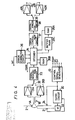
- Figure 3 is a block diagram illustrating a preferred embodiment of an apparatus for recording an analog signal and according to the present invention;
- Figure 4 is a block diagram illustrating a preferred embodiment of apparatus for reproducing an analog signal, as might be recorded by the apparatus of Figure 3 and according to the present invention;
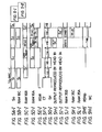
- Figures 5A to 5N are timing charts and waveforms representing recording and/or reproducing operations;
- Figure 6 is a schematic illustration of another example of a rotary head assembly used in a method and apparatus for recording and/or reproducing an analog signal and according to the present invention;
- Figure 7 is a timing chart representing the timing of a recording system; and
- Figure 8 is a schematic illustration of another example of a rotary head assembly used in a method and apparatus for recording and/or reproducing an analog signal and according to the present invention.
- Figure 1 schematically illustrates a rotary head assembly, as used in an embodiment of the present invention, that includes two magnetic heads lA and 1B mounted on a rotating drum (not shown). In this assembly, the two
rotary heads magnetic tape 2 on which the signals are to be recorded and/or reproduced is wrapped around the peripheral surface of a tape guide drum 3 over an angular extent of 180°. - We have previously disclosed a recording apparatus in which the magnetic tape is wound around the peripheral surface of a tape guide drum over an angular extent of 900 and the speed at which the rotary head rotates is 30 revolutions per second. This rotary head speed can be taken as a reference rotation speed, and in this embodiment of the present invention the
heads heads - In this embodiment, when the
tape 2 is transported at a predetermined speed in a direction shown generally by anarrow 5T theheads magnetic tracks magnetic tracks tape 2 by theheads head 1A is traced by thehead 1B in exactly the same way. Note that in the embodiment of Figure 1, there is no free period when the two heads IA and 1B are both out of contact with thetape 2. - Figure 3 shows an example of the recording system in which an analog audio signal is recorded as a two channel signal, comprising left and right audio channels. A left-channel analog audio signal 5L is supplied through an
input terminal 11L to one input terminal of aswitching circuit 12, and a right-channel analog audio signal SR is applied through aninput terminal 11R to the other input terminal of theswitching circuit 12. Theswitching circuit 12 is changed over alternately in position in response to a switching signal SW, which is a square-wave signal having a duty factor of 50%. The switching signal SW is derived from a controlsignal generator circuit 13 at a frequency of 44.1 kHz and controls theswitching circuit 12 so that theswitching circuit 12 changes over at each period during which the signal SW is at a high level or at a low level. Accordingly, theswitching circuit 12 alternately supplies the left channel signal 5L and the right channel signal SR to an analog-to-digital (A/D)converter 14. In the A/D converter 14 this signal is sampled at a sampling frequency of 44.1 kHz per channel, and then this sampled signal is converted to a pulse code modulation (PCM) signal that in this embodiment may comprise sixteen bits per sample, for example. - The output signal S0 from the A/
D converter 14 is fed to arecording encoder 15, and the output signal S0 is shown in the timing charts at Figure 5A. Therecording encoder 15 is connected to suitable memory circuits, specifically, a random access memory (RAM) 16A is directly connected to an output of therecording encoder 15 and abuffer RAM 16C is connected between an output of therecording encoder 15 and a secondrandom access memory 16B. Thebuffer RAM 16C operates to delay the data input to theRAM 16B to provide the desired time delay. Also connected to an input/output interface of therecording encoder 15 is a parity word and cyclic redundancy check (CRC) code generating and adding circuit 17. A control signal RSW, the timing waveform of which is shown in Figure 5E, is produced by thecontrol signal generator 13 and fed to therecording encoder 15, which operates in response thereto to switch the PCM data signal S0 every 1/60 of a second, which corresponds to the duration of time required for one revolution of theheads heads recording encoder 15 in response to the control signal RSW, is then written into theRAMs - The PCM signals S1, S2, S3 ..... , which have periods of 1/60 of a second, are separated in the
recording encoder 15 so that alternate ones of the signals S2, S4, S6 ..... , are written directly into theRAM 16A; the timing of this being shown at Figure 5D. Similarly, the remaining ones of the PCM signals, that is S1, S31 S5 ..... , are fed into thebuffer RAM 16C where they are delayed in time by an amount corresponding to one-half a revolution period of the rotary heads IA and 1B, that is, 1/120 of a second, and thereby become signals S1', S3', S5', ..... , and are then written into theRAM 16B. The timing of the signals into thebuffer RAM 16C and theRAM 16B are shown in Figures 5B and 5C, respectively. - As shown in Figures 5C and 5D, the PCM data having a period of 1/60 of a second is written into the
RAMs RAMs recording encoder 15. The controlsignal generating circuit 13 generates the appropriate control signal CP that actuates the CRC adding circuit 17. Once the PCM signals have had the parity and CRC code added thereto they are written back into theRAMs RAMs head 1A or the head I B. - As is made clear in Figure 5, the period during which the PCM data having the compressed time-base is read out from the
RAMs heads RAM 16B, whereas during the second half-period TA of the period TR, or 1/120 of a second, the PCM data having the compressed time-base is read out from theRAM 16A. As described above, the data of each unit period having the compressed time-base read from theRAMs recording encoder 15 is then supplied through arecording amplifier 18 to a respective one of the two heads lA and lB. The controlsignal generating circuit 13 produces a reference signal CT, the waveform of which is shown in Figure 5F, having a frequency of 30 Hz that is fed to aservo circuit 20 so that theheads head 1 A scans thetape 2, while during the period TB thehead 1B scans thetape 2, thus, the reference signal CT that has a phase different than that of the control signal RSW by π /2 is fed to theservo circuit 20. The feedback to theservo circuit 20 is provided by apulse generator 21 that generates a pulse signal PG of frequency 30 Hz so that a pulse is present each time theheads servo circuit 20 is fed to a headdrum drive motor 22 which applies the phase servo to theheads head 1A commences contact with thetape 2 at a time corresponding to the occurrence of the trailing edge of the square-wave reference signal CT. - If the period of time from which the
head 1A first commences contact with thetape 2 to the time when thehead 1A again commences contact with thetape 2 is taken as a unit rotational interval P, a first-half rotation period HA in the unit rotational interval P is the period during which the head lA scans thetape 2, whereas the second-half rotation period HB in the unit rotational interval P is the period in which thehead 1B scans thetape 2. Thus, as shown in Figure 5, the read period TB from theRAM 16B corresponds to every other contact period HB of thehead 1B with thetape 2, while the read period TA from theRAM 16A corresponds to every other contact period HA of the head lA with thetape 2. Moreover, the second half-period HB in the unit rotational interval P and the first half-period HA in the succeeding unit rotational interval P are coincident with these very same read periods TB and TA, respectively. - Therefore, there is recorded on the
tape 2 PCM time-base compressed data having a period of 1/60 of a second by the head IB in a certain unit rotational interval P thereby forming thetrack 4B, whereas there is also recorded on thetape 2 PCM time-base compressed data having a period of 1/60 of a second by thehead 1A during the first half-period HA in the succeeding unit rotational interval P thereby forming thetrack 4A. Although during the second half-period HB in the unit rotational interval P the head IB scans thetrack 4A no recorded signal exists during this period and, thus, the signal recorded by the head IA remains in thetrack 4A. Similarly, although in the first half-period HA and the succeeding unit rotational interval P thehead 1A scans thetape 2 such that a track adjoining thetrack 4A will be formed, during this period HA no signal exists and accordingly no record track is formed. Thereafter, when the second half-period HB occurs, PCM data is read out from theRAM 16B and supplied to thehead 1B so that thetrack 4B is formed by thehead 1B on which the time-base compressed PCM data is recorded. The above operations are repeated successively and thetracks - The control signal CT produced by the
control signal generator 13 is also fed through arecording amplifier 23 to a stationerymagnetic head 24, and the time control signal is thereby recorded along an edge of thetape 2 as acontrol pulse track 6C utilized in the playback mode. Thecontrol pulse track 6C is seen in relation to thetape 2 in Figure 2. - Following a recording operation such as described above the audio PCM signal can be reproduced in the following fashion utilizing apparatus as shown in Figure 4. In the reproducing system shown in Figure 4, a pulse signal having a frequency of 30 Hz is reproduced from the
control pulse track 6C on thetape 2 by thestationary head 24, and this pulse signal is fed to theservo circuit 20 and also to the controlsignal generator circuit 13. The pulse signal PG produced by thepulse generator 21 is also fed to theservo circuit 20, so that theheads tracks heads - The output signals produced by the heads IA and 1B are fed through
amplifiers circuit 32. The switchingcircuit 32 alternately selects one or the other of the input terminals in response to a switching control signal SH that has a frequency of 30 Hz, the waveform of which is shown in Figure 5G, and which is produced by the controlsignal generator circuit 13. Thus, the switchingcircuit 32 alternately produces a reproduced output from theheads circuit 32 is fed to a digital restoringcircuit 33 that operates to restore the signal to a digital signal by cleaning and shaping the reproduced waveform, and the restored digital signal is fed to adecoder 34 which it is decoded to the original PCM data signal S0. In thedecoder 34 the signal processing is carried out by means ofRAMs signal generator circuit 13. As seen in Figure 5M, the control signal RSWP changes over between a high-level period TWB and a low-level period TWA, and in the first half of the period TWB the output data reproduced by thehead 1B is written into theRAM 35B, while in the second half of the period TWB the output data reproduced by thehead 1A is delayed by a time of 1/120 of a second by means of thebuffer RAM 35C and then subsequently written into theRAM 35A during the first half of the period TWA. The PCM data written into theRAMs error correcting circuit 36 during the second half portions of the 1/120 of a second periods of the periods TWB and TWA, respectively. That is, since a control signal WC supplied to theerror corrector circuit 36 from the controlsignal generator circuit 13 goes high during the second half of the periods TWB and TWA, theerror correcting circuit 36 is operated for error correction during those times. The waveform of control signal WC is shown in Figure 5N-I. Accordingly, error correction is performed within the error correction ability range by use of the parity word and the CRC code. - The reproduced data of one track amount that were written in the
RAMs decoder unit 34 is fed to an error concealing orerror correcting circuit 37, which acts to conceal any errors which could not be corrected by theerror correcting circuit 36. This technique is well-known and various value holding systems are known to accomplish error concealment. The output signal from theerror correcting circuit 37 is fed to a digital-to- analog (D/A)converter 38, wherein it is returned to an analog signal and fed to aswitching circuit 39. The switchingcircuit 39 is alternately changed over in response to a switching signal SW, which is identical to the switching signal SW utilized during the recording operation, and the audio signals of the left channel and right channel are thus demodulated and respectively supplied throughamplifiers output terminals - Although in the above-described embodiment two rotary heads lA and 1B are located with an angular separation of 180° therebetween and are displaced in the rotational axial direction so that the scanning locus by the
head 1A is scanned in exactly the same way by thehead 1B, is also possible to utilize the embodiment represented in Figure 6, wherein the tworotary heads heads tape 2 during only one-half of the revolution period corresponding to the wrap angle of thetape 2 around the periphery of the guide drum 3 and, accordingly, both scan the same scanning locus. More specifically, the heads lA and IB contact thetape 2 at each half revolution of the rotary head assembly, thus, when theheads head 1A during a certain one-revolution period and only by thehead 1B during the successive one-revolution period, as represented by the hatched portions in Figure 7. The PCM signal corresponding to the one-revolution period of the heads lA and 1B, that is, one-half revolution period amount of the reference speed, namely, the angular spacing amount of 180° that represents the tape wrap angle, can be recorded as each track that has added thereto the error correction parity word and the like and this is compressed in time-base to one-half. - In a still further embodiment, as represented in Figure 8, the rotary heads 1A and IB are mounted with an angular distance of 180° therebetween, however, the wrap angle of the tape about the periphery of the guide drum 3 is much smaller than the head separation angular distance of 180°. In Figure 8, the tape wrap angle is one half of the head separation angular distance and is 90°, accordingly, the time-base of the recorded signal can be compressed further by an additional half, that is, compressed to one-quarter of the original time base.
- Based upon the above it can be seen that the time-base compression ratio of the PCM signal is determined by the number n of rotary heads, the multiplied speed ratio N of the rotary heads relative to a reference speed, and the tape wrap angle a ° of the
tape 2 about the guide drum 3, where a 0 is less than or equal to 360°. Accordingly, the time-base compression ratio D can be determined by the following expression:
- Moreover, while the above description of the invention is based upon a case utilizing two rotary heads, the present invention also applies to systems in which there is only one rotary head and to systems in which there are more than two rotary heads. Accordingly, all that is required in equation (1) is that n, the number of heads, be a positive integer. Moreover, the rotational speed that is multiplied by the ratio N of the rotary head is not limited to twice the reference speed but can be selected to be any integral multiple thereof, such as three or four times. It is also possible to select a multiple of the reference speed which is not an integral and such multiples could comprise 1.5 times, 1.8 times or the like. Nevertheless, in such case if the ratio N is selected to be an integral multiple then the recording timing control for the rotary head, as well as the time-base compression processing of the PCM signal, is made substantially easier to implement.
- Accordingly, as described above, since the rotational speed of the rotary head is selected to be N times a reference speed, where N is greater than 1, and the tape wrap angle a , where α° is less than or equal to 360°, is determined relative to the number of heads and the head mounting angular distance, the PCM data can be compressed in time-base with a predetermined compression ratio and ultimately recorded on the tape. Moreover, since a period in which no PCM signal is recorded by any one of the rotary heads is provided by the above time-base compression, that period can be effectively utilized to accomplish the desired error correction. Furthermore, time-base compression can be carried out utilizing only a minimal number of memory units.
- Since the PCM signal is compressed in time-base and then recorded, the bit rate of the recorded PCM signal can be increased. In the case of the rotary head assembly, supplying and deriving the signal to and from the rotary head is achieved through a rotary transformer and, thus, the increase of the transmission band allows supplying and deriving the signal to and from the rotary head in an easier fashion. Another advantageous effect is provided in that the transmission band can be made higher than the band of the time-base error in which wow and flutter would typically occur and, thus, the adverse effects of wow and flutter are suppressed.
- Furthermore, since the rotational speed of the rotary head is selected to be higher than the reference speed, it is possible to raise the relative speed of the head in relation to the transport of the tape and, thus, recording head output bandwidth can be improved. Also, when the PCM signal is recorded and/or reproduced from the magnetic tape with predetermined compression ratio, the number n of rotary heads, the rotational speed N of the rotary head, and the tape wrap angle a° can be selected. This means that when the tape wrap angle a 0 can be increased, the diameter of the guide drum 3 can be made smaller and, hence, the capability to reduce the overall size of the recording apparatus is provided.
- Additionally, as set forth above, since there occurs a period during which no signal is recorded on the tape by either of the two heads, the tape can be transported only during such period and recording by the rotary head can be carried out during the period when the tape is stopped. Therefore, even although the tape speed is changed depending on the use, the record track is formed in the mode wherein the tape is stopped so that record tracks are formed with the same angle of inclination with respect to the longitudinal axis of the tape. This means that variable speed playback effects such as fast forward and slow motion, for example, can be facilitated with relative ease.
Claims (17)
Priority Applications (1)
| Application Number | Priority Date | Filing Date | Title |
|---|---|---|---|
| AT83307958T ATE42007T1 (en) | 1982-12-27 | 1983-12-23 | METHOD AND DEVICE FOR RECORDING AND REPRODUCTION OF ANALOG SIGNALS. |
Applications Claiming Priority (2)
| Application Number | Priority Date | Filing Date | Title |
|---|---|---|---|
| JP230599/82 | 1982-12-27 | ||
| JP57230599A JPS59119519A (en) | 1982-12-27 | 1982-12-27 | Recorder of pcm signal |
Publications (2)
| Publication Number | Publication Date |
|---|---|
| EP0115699A1 true EP0115699A1 (en) | 1984-08-15 |
| EP0115699B1 EP0115699B1 (en) | 1989-04-05 |
Family
ID=16910265
Family Applications (1)
| Application Number | Title | Priority Date | Filing Date |
|---|---|---|---|
| EP83307958A Expired EP0115699B1 (en) | 1982-12-27 | 1983-12-23 | Methods and apparatus for recording and reproducing analog signals |
Country Status (7)
| Country | Link |
|---|---|
| US (1) | US4544958A (en) |
| EP (1) | EP0115699B1 (en) |
| JP (1) | JPS59119519A (en) |
| AT (1) | ATE42007T1 (en) |
| AU (1) | AU566649B2 (en) |
| CA (1) | CA1214267A (en) |
| DE (1) | DE3379559D1 (en) |
Cited By (7)
| Publication number | Priority date | Publication date | Assignee | Title |
|---|---|---|---|---|
| GB2166278A (en) * | 1984-10-23 | 1986-04-30 | Peter John Court Marlow | Sound recording interface for a domestic video cassette recorder |
| EP0191469A2 (en) * | 1985-02-14 | 1986-08-20 | Sony Corporation | Audio signal recording and/or reproducing apparatus |
| EP0209141A2 (en) * | 1985-07-19 | 1987-01-21 | Hitachi, Ltd. | PCM Signal recording and reproducing apparatus |
| EP0257991A2 (en) * | 1986-08-21 | 1988-03-02 | Sony Corporation | Apparatus for reproducing a digital signal |
| EP0303230A2 (en) * | 1987-08-12 | 1989-02-15 | Hitachi, Ltd. | PCM signal reproducing/recording apparatus |
| EP0509806A2 (en) * | 1991-04-18 | 1992-10-21 | Sony Corporation | A magnetic recording apparatus having a small rotary head drum |
| CN108694100A (en) * | 2017-04-06 | 2018-10-23 | 株式会社村田制作所 | Data converting apparatus |
Families Citing this family (13)
| Publication number | Priority date | Publication date | Assignee | Title |
|---|---|---|---|---|
| US4675754A (en) * | 1984-02-21 | 1987-06-23 | Mitsubishi Denki Kabushiki Kaisha | Magnetic recorder/reproducer |
| US4839745A (en) * | 1984-06-25 | 1989-06-13 | Kirsch Technologies, Inc. | Computer memory back-up |
| US5138498A (en) * | 1986-10-22 | 1992-08-11 | Fuji Photo Film Co., Ltd. | Recording and reproduction method for a plurality of sound signals inputted simultaneously |
| US4943964A (en) * | 1987-08-12 | 1990-07-24 | Hitachi, Ltd. | PCM signal reproducing device |
| JP2721011B2 (en) * | 1989-07-25 | 1998-03-04 | 三菱電機株式会社 | Digital signal recording device |
| US5530598A (en) * | 1990-07-06 | 1996-06-25 | Hitachi, Ltd. | Digital transmission signal processing system and recording/reproducing system |
| US6002536A (en) * | 1990-07-06 | 1999-12-14 | Hitachi Ltd. | Digital transmission signal processing system and recording/reproducing system |
| US5337199A (en) * | 1990-07-06 | 1994-08-09 | Hitachi, Ltd. | Digital transmission signal processing system and recording/reproducing system |
| US5384666A (en) * | 1990-11-14 | 1995-01-24 | Sony Corporation | Digital picture signal recording apparatus in which a field interval is recorded in a plurality of tracks exhibiting a track pitch no greater than 5.5 μm by a rotary drum having a diameter no greater than 25 mm and a rotary speed no less than 150 rps |
| JPH04179380A (en) * | 1990-11-14 | 1992-06-26 | Sony Corp | Magnetic recorder for digital picture signal |
| JPH04238160A (en) * | 1991-01-21 | 1992-08-26 | Sony Corp | Signal reproducing device |
| US5615055A (en) * | 1991-01-25 | 1997-03-25 | Sony Corporation | Dual-mode digital signal recording and/or reproducing apparatus |
| DE69225103T2 (en) * | 1991-08-28 | 1998-08-20 | Japan Broadcasting Corp | Method and device for generating a copy signal at high speed |
Citations (3)
| Publication number | Priority date | Publication date | Assignee | Title |
|---|---|---|---|---|
| GB1127229A (en) * | 1964-11-12 | 1968-09-18 | Ampex | Method of reproducing signals recorded in oblique tracks on a magnetic tape |
| GB2062313A (en) * | 1979-10-26 | 1981-05-20 | Sony Corp | Time base converters |
| GB2082825A (en) * | 1980-08-06 | 1982-03-10 | Sony Corp | Coded signal reproducing arrangements |
Family Cites Families (4)
| Publication number | Priority date | Publication date | Assignee | Title |
|---|---|---|---|---|
| US4206476A (en) * | 1976-02-24 | 1980-06-03 | Sony Corporation | Control circuit for use with a time-compression/time-expansion system in a pulse signal record/playback device |
| DE2939962A1 (en) * | 1978-10-02 | 1980-05-14 | Kanbayashi Seisakujo Co | Time compression expansion of tape recorded speech - using variable ratios selected by operator and avoiding speech distortion by accurate matching |
| DE3044624A1 (en) * | 1980-11-27 | 1982-06-24 | Robert Bosch Gmbh, 7000 Stuttgart | METHOD FOR DIGITAL RECORDING OF VIDEO SIGNALS |
| US4413289A (en) * | 1981-03-13 | 1983-11-01 | Sri International | Digital recording and playback method and apparatus |
-
1982
- 1982-12-27 JP JP57230599A patent/JPS59119519A/en active Granted
-
1983
- 1983-12-20 AU AU22591/83A patent/AU566649B2/en not_active Expired
- 1983-12-20 CA CA000443847A patent/CA1214267A/en not_active Expired
- 1983-12-23 AT AT83307958T patent/ATE42007T1/en not_active IP Right Cessation
- 1983-12-23 DE DE8383307958T patent/DE3379559D1/en not_active Expired
- 1983-12-23 EP EP83307958A patent/EP0115699B1/en not_active Expired
- 1983-12-23 US US06/564,890 patent/US4544958A/en not_active Expired - Lifetime
Patent Citations (3)
| Publication number | Priority date | Publication date | Assignee | Title |
|---|---|---|---|---|
| GB1127229A (en) * | 1964-11-12 | 1968-09-18 | Ampex | Method of reproducing signals recorded in oblique tracks on a magnetic tape |
| GB2062313A (en) * | 1979-10-26 | 1981-05-20 | Sony Corp | Time base converters |
| GB2082825A (en) * | 1980-08-06 | 1982-03-10 | Sony Corp | Coded signal reproducing arrangements |
Cited By (16)
| Publication number | Priority date | Publication date | Assignee | Title |
|---|---|---|---|---|
| GB2166278A (en) * | 1984-10-23 | 1986-04-30 | Peter John Court Marlow | Sound recording interface for a domestic video cassette recorder |
| EP0191469A3 (en) * | 1985-02-14 | 1988-09-14 | Sony Corporation | Audio signal recording and/or reproducing apparatus |
| EP0191469A2 (en) * | 1985-02-14 | 1986-08-20 | Sony Corporation | Audio signal recording and/or reproducing apparatus |
| EP0209141A2 (en) * | 1985-07-19 | 1987-01-21 | Hitachi, Ltd. | PCM Signal recording and reproducing apparatus |
| EP0209141A3 (en) * | 1985-07-19 | 1987-07-22 | Hitachi, Ltd. | Pcm signal recording and reproducing apparatus |
| US4758902A (en) * | 1985-07-19 | 1988-07-19 | Hitachi, Ltd. | PCM signal recording and reproducing apparatus including simultaneous error detection/correction |
| EP0257991A3 (en) * | 1986-08-21 | 1989-05-10 | Sony Corporation | Methods of and apparatus for reproducing a digital signal |
| EP0257991A2 (en) * | 1986-08-21 | 1988-03-02 | Sony Corporation | Apparatus for reproducing a digital signal |
| US4875111A (en) * | 1986-08-21 | 1989-10-17 | Sony Corporation | Apparatus for reproducing a digital signal |
| EP0303230A2 (en) * | 1987-08-12 | 1989-02-15 | Hitachi, Ltd. | PCM signal reproducing/recording apparatus |
| EP0303230A3 (en) * | 1987-08-12 | 1991-04-24 | Hitachi, Ltd. | Pcm signal reproducing/recording apparatus |
| EP0509806A2 (en) * | 1991-04-18 | 1992-10-21 | Sony Corporation | A magnetic recording apparatus having a small rotary head drum |
| EP0509806A3 (en) * | 1991-04-18 | 1993-01-13 | Sony Corporation | A magnetic recording apparatus having a small rotary head drum |
| US5337192A (en) * | 1991-04-18 | 1994-08-09 | Sony Corporation | Magnetic recording and/or reproducing apparatus having tape guide cylinder of reduced diameter and increased tape wrap angle |
| CN108694100A (en) * | 2017-04-06 | 2018-10-23 | 株式会社村田制作所 | Data converting apparatus |
| CN108694100B (en) * | 2017-04-06 | 2022-06-24 | 株式会社村田制作所 | Data conversion device |
Also Published As
| Publication number | Publication date |
|---|---|
| JPH0357527B2 (en) | 1991-09-02 |
| EP0115699B1 (en) | 1989-04-05 |
| US4544958A (en) | 1985-10-01 |
| JPS59119519A (en) | 1984-07-10 |
| AU2259183A (en) | 1984-07-05 |
| ATE42007T1 (en) | 1989-04-15 |
| DE3379559D1 (en) | 1989-05-11 |
| AU566649B2 (en) | 1987-10-29 |
| CA1214267A (en) | 1986-11-18 |
Similar Documents
| Publication | Publication Date | Title |
|---|---|---|
| EP0115699B1 (en) | Methods and apparatus for recording and reproducing analog signals | |
| US4523237A (en) | Method and apparatus for recording and reproducing an analog signal | |
| US4375100A (en) | Method and apparatus for encoding low redundancy check words from source data | |
| US4393502A (en) | Method and apparatus for communicating digital information words by error-correction encoding | |
| US4562578A (en) | Method for data transmission | |
| EP0130091B1 (en) | Apparatus for recording and/or reproducing digital information signals | |
| EP0209141A2 (en) | PCM Signal recording and reproducing apparatus | |
| JPH0661156B2 (en) | Encoding method for error correction | |
| EP0238194A2 (en) | Methods of and apparatus for recording signals on a disc-shaped recording medium | |
| EP0232093B1 (en) | Data transmission and recording methods | |
| US4549230A (en) | Redundantly and asynchronously recording an information signal | |
| US5504631A (en) | Magnetic recording/reproducing apparatus provides error corrections in write-after-read processing | |
| JPS59117713A (en) | Transmitting device of digital audio signal | |
| JPH0572002B2 (en) | ||
| JPH0697543B2 (en) | Recording device for PCM data | |
| JPH0583983B2 (en) | ||
| JPH0242686A (en) | Rotary head type magnetic recording and reproducing device and system for recording and reproducing | |
| JPS60191471A (en) | Double speed reproducing method of pcm signal | |
| JP2546189B2 (en) | Rotating head type magnetic reproducing apparatus and signal processing circuit used therefor | |
| US6269219B1 (en) | Recording four channels of digital audio data on two channels of a magnetic tape | |
| JP2546190B2 (en) | Signal processing circuit for rotary head type magnetic reproducing device | |
| JPH05234265A (en) | Rotary head type magnetic recording and reproducing, signal processing circuit and magnetic tape | |
| JPH0551989B2 (en) | ||
| JPS60191472A (en) | Double-speed reproducing device of pcm signal | |
| JPH08130711A (en) | Digital information recording and reproducing device |
Legal Events
| Date | Code | Title | Description |
|---|---|---|---|
| PUAI | Public reference made under article 153(3) epc to a published international application that has entered the european phase |
Free format text: ORIGINAL CODE: 0009012 |
|
| AK | Designated contracting states |
Designated state(s): AT CH DE FR GB IT LI NL |
|
| 17P | Request for examination filed |
Effective date: 19841127 |
|
| 17Q | First examination report despatched |
Effective date: 19860923 |
|
| D17Q | First examination report despatched (deleted) | ||
| GRAA | (expected) grant |
Free format text: ORIGINAL CODE: 0009210 |
|
| AK | Designated contracting states |
Kind code of ref document: B1 Designated state(s): AT CH DE FR GB IT LI NL |
|
| REF | Corresponds to: |
Ref document number: 42007 Country of ref document: AT Date of ref document: 19890415 Kind code of ref document: T |
|
| REF | Corresponds to: |
Ref document number: 3379559 Country of ref document: DE Date of ref document: 19890511 |
|
| ITF | It: translation for a ep patent filed |
Owner name: SOCIETA' ITALIANA BREVETTI S.P.A. |
|
| ET | Fr: translation filed | ||
| PLBE | No opposition filed within time limit |
Free format text: ORIGINAL CODE: 0009261 |
|
| STAA | Information on the status of an ep patent application or granted ep patent |
Free format text: STATUS: NO OPPOSITION FILED WITHIN TIME LIMIT |
|
| 26N | No opposition filed | ||
| ITTA | It: last paid annual fee | ||
| PGFP | Annual fee paid to national office [announced via postgrant information from national office to epo] |
Ref country code: FR Payment date: 20011212 Year of fee payment: 19 Ref country code: AT Payment date: 20011212 Year of fee payment: 19 |
|
| PGFP | Annual fee paid to national office [announced via postgrant information from national office to epo] |
Ref country code: GB Payment date: 20011227 Year of fee payment: 19 |
|
| PGFP | Annual fee paid to national office [announced via postgrant information from national office to epo] |
Ref country code: NL Payment date: 20011228 Year of fee payment: 19 |
|
| REG | Reference to a national code |
Ref country code: GB Ref legal event code: IF02 |
|
| PGFP | Annual fee paid to national office [announced via postgrant information from national office to epo] |
Ref country code: DE Payment date: 20020109 Year of fee payment: 19 |
|
| PGFP | Annual fee paid to national office [announced via postgrant information from national office to epo] |
Ref country code: CH Payment date: 20020115 Year of fee payment: 19 |
|
| PG25 | Lapsed in a contracting state [announced via postgrant information from national office to epo] |
Ref country code: GB Free format text: LAPSE BECAUSE OF NON-PAYMENT OF DUE FEES Effective date: 20021223 Ref country code: AT Free format text: LAPSE BECAUSE OF NON-PAYMENT OF DUE FEES Effective date: 20021223 |
|
| PG25 | Lapsed in a contracting state [announced via postgrant information from national office to epo] |
Ref country code: LI Free format text: LAPSE BECAUSE OF NON-PAYMENT OF DUE FEES Effective date: 20021231 Ref country code: CH Free format text: LAPSE BECAUSE OF NON-PAYMENT OF DUE FEES Effective date: 20021231 |
|
| PG25 | Lapsed in a contracting state [announced via postgrant information from national office to epo] |
Ref country code: NL Free format text: LAPSE BECAUSE OF NON-PAYMENT OF DUE FEES Effective date: 20030701 Ref country code: DE Free format text: LAPSE BECAUSE OF NON-PAYMENT OF DUE FEES Effective date: 20030701 |
|
| GBPC | Gb: european patent ceased through non-payment of renewal fee |
Effective date: 20021223 |
|
| REG | Reference to a national code |
Ref country code: CH Ref legal event code: PL |
|
| NLV4 | Nl: lapsed or anulled due to non-payment of the annual fee |
Effective date: 20030701 |
|
| PG25 | Lapsed in a contracting state [announced via postgrant information from national office to epo] |
Ref country code: FR Free format text: LAPSE BECAUSE OF NON-PAYMENT OF DUE FEES Effective date: 20030901 |
|
| REG | Reference to a national code |
Ref country code: FR Ref legal event code: ST |