EP0132232A2 - An MTD digital processor for surveillance radar with a bank of Doppler filters and system of thresholds both selectable and dependent on the interference - Google Patents
An MTD digital processor for surveillance radar with a bank of Doppler filters and system of thresholds both selectable and dependent on the interference Download PDFInfo
- Publication number
- EP0132232A2 EP0132232A2 EP84830142A EP84830142A EP0132232A2 EP 0132232 A2 EP0132232 A2 EP 0132232A2 EP 84830142 A EP84830142 A EP 84830142A EP 84830142 A EP84830142 A EP 84830142A EP 0132232 A2 EP0132232 A2 EP 0132232A2
- Authority
- EP
- European Patent Office
- Prior art keywords
- radar
- digital processor
- fact
- filters
- clutter
- Prior art date
- Legal status (The legal status is an assumption and is not a legal conclusion. Google has not performed a legal analysis and makes no representation as to the accuracy of the status listed.)
- Granted
Links
Images


Classifications
-
- G—PHYSICS
- G01—MEASURING; TESTING
- G01S—RADIO DIRECTION-FINDING; RADIO NAVIGATION; DETERMINING DISTANCE OR VELOCITY BY USE OF RADIO WAVES; LOCATING OR PRESENCE-DETECTING BY USE OF THE REFLECTION OR RERADIATION OF RADIO WAVES; ANALOGOUS ARRANGEMENTS USING OTHER WAVES
- G01S13/00—Systems using the reflection or reradiation of radio waves, e.g. radar systems; Analogous systems using reflection or reradiation of waves whose nature or wavelength is irrelevant or unspecified
- G01S13/02—Systems using reflection of radio waves, e.g. primary radar systems; Analogous systems
- G01S13/50—Systems of measurement based on relative movement of target
- G01S13/52—Discriminating between fixed and moving objects or between objects moving at different speeds
- G01S13/522—Discriminating between fixed and moving objects or between objects moving at different speeds using transmissions of interrupted pulse modulated waves
- G01S13/524—Discriminating between fixed and moving objects or between objects moving at different speeds using transmissions of interrupted pulse modulated waves based upon the phase or frequency shift resulting from movement of objects, with reference to the transmitted signals, e.g. coherent MTi
- G01S13/5244—Adaptive clutter cancellation
-
- G—PHYSICS
- G01—MEASURING; TESTING
- G01S—RADIO DIRECTION-FINDING; RADIO NAVIGATION; DETERMINING DISTANCE OR VELOCITY BY USE OF RADIO WAVES; LOCATING OR PRESENCE-DETECTING BY USE OF THE REFLECTION OR RERADIATION OF RADIO WAVES; ANALOGOUS ARRANGEMENTS USING OTHER WAVES
- G01S13/00—Systems using the reflection or reradiation of radio waves, e.g. radar systems; Analogous systems using reflection or reradiation of waves whose nature or wavelength is irrelevant or unspecified
- G01S13/02—Systems using reflection of radio waves, e.g. primary radar systems; Analogous systems
- G01S13/50—Systems of measurement based on relative movement of target
- G01S13/52—Discriminating between fixed and moving objects or between objects moving at different speeds
- G01S13/522—Discriminating between fixed and moving objects or between objects moving at different speeds using transmissions of interrupted pulse modulated waves
- G01S13/524—Discriminating between fixed and moving objects or between objects moving at different speeds using transmissions of interrupted pulse modulated waves based upon the phase or frequency shift resulting from movement of objects, with reference to the transmitted signals, e.g. coherent MTi
- G01S13/5248—Discriminating between fixed and moving objects or between objects moving at different speeds using transmissions of interrupted pulse modulated waves based upon the phase or frequency shift resulting from movement of objects, with reference to the transmitted signals, e.g. coherent MTi combining a coherent MTI processor with a zero Doppler processing channel and a clutter mapped memory, e.g. MTD (Moving target detector)
Definitions
- This invention concerns a digital processor for surveillance radar, in particular for air traffic control but not limited only to this; it is formed by a bank of transverse filters which cover the unambiguous Doppler frequency interval, with Doppler frequency response selectable for each filter in order to adapt the filtering to the interference characteristics produced by unwanted echoes (clutter).
- This processor is denominated A-MTD adaptive-MTD because of the adaptivity characteristic which distinguishes it from the conventional Moving Target Detector (MTD) processor and it will be referred to by this name from now on.
- MTD Moving Target Detector
- the selectable filtering of this invention and the selectability between fixed and adaptive thresholds allow the limitations encountered in fixed filtering to be overcome, by optimizing capability of detecting target in various types of interference.
- the invention described here is within the field of radar systems and in particular of radar signal processor.
- the signal processor at present realized with digital type circuits, receive the radar video signal at the input, coherently detected and converted to digital form. At the output they furnish the indication of the targets present (detection process) eliminating, as far as possible,unwanted signals.
- the elimination of the unwanted signals resulting from reflections from natural or artificial obstacles (clutter) is achieved in the current radar technique with the MTI (Moving Target Indicator) type of filtering, described in many technical articles and books, such as:
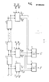
- This processor (Fig. 1) is constituted by a bank of Doppler filters 3 (from six to ten filters: generally for the majority of applications the number is eight), each one followed by a modulus-extractor 5 , by an adaptive threshold circuit 6 , commony known as an "Autogate", and finally by the recombining logic of the different outputs 7 .
- the "Autogate” is well known is radar techniques; reference may be made, for example, to:
- the system of selection of the type of filtering of the radar signal is controlled by means of a clutter map (in part fixed for the ground clutter, in part dynamically adjustable for the rain clutter) with which the processor is equipped.
- a bank of Doppler filters is selected with more or less severe filtering characteristics, according to whether in the zone which the radar is exploring there is more or less intense interference present.
- a further facility is that of disengaging the "Autogate" circuit in the absence of rain, and in its place inserting a fixed threshold, to recover the sensitivity in the detection.
- the type of filter used in this bank are transverse, i:e. they are filters with a fixed structure, where the frequency response depends entirely on the coefficients W .... W employed (Fig. 2). Therefore selecting the filtering means selecting the set of'weights' W i which gives the desired frequency response.
- a further recovery of sensitivity is obtained in the present invention by means of a threshold that can be fixed or adaptive (autogate), since the insertion of the autogate leads to a loss of sensitivity [9] .
- the selection of the type of filtering is realized by the use of a bank of transverse filters in which the set of W coefficients is changed for each filter.
- the rain clutter has been implicitly taken into account by synthesizing the frequency responses with the side lobes as low as possible,compatible with the need of high gain in the signal -to- noise ratio.
- Fig. 1 Block 2 a set of weights has been synthesized to realize a "zero filter", (Fig. 1 Block 2), tuned on zero Doppler frequency with a very narrow main lobe and extremely low side lobes (around -40 dB with respect to the main lobe level).
- This filters are to allow reception in the bands which are normally opaque due to the presence of ground clutter so that the clutter map may be updated and possibly tangential targets may be detected.
- weights are represented in fixed point digital form and precisely as 8-bit integer coefficients.
- Fig. 1 shows the A-MTD processor in its preferred general configuration in which the blocks represent:
- Fig. 2 shows one of the typical filters of the bank of Doppler filters indicated by 2 and 3 in Fig. 1.
- Fig. 2 there is the complex multiplying 17, the delay element 18 and the data summer at the output of the complex multiplier.
- the same filter can be realized by using a recursive structure; in this case a single delay element would suffice, a single complex multiplier and an accumulator summer.
- Fig. 3 shows in detail the complex multiplier contained in Fig. 2 and indicated with 17: the multiplier is (X R + jX S ), the multiplicand is (Y R + jY I ) and the result is (Y R Y R - X I Y I ) + j (X I Y R + X R Y I ).
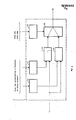
- Fig. 4 shows the threshold circuit which forms block 6 of Fig. 1.
- the video signal coherently detected is converted into digital form by the block 1 to then be fed to the input of the bank of.Doppler filters 2, 3, 4 and simultaneously to the rain sensor.
- the output of the Doppler filters are modulus detected 5, and fed to the threshold circuits 6.
- the loading logic circuit, 11 updates the rain map memory, 12, the function of which is to select the fixed or adaptive threshold contained in the threshold circuit, 6.
- the output of the modulus esctrator, 5, connected to the "zero filter” allows, by means of a ground clutter level measuring circuit, 13, and an updating logic circuit, 8, the loading of the weight selection map Memory, 9.
- the weight selection devices, 4, of each of the Doppler filters, are commanded by means of the weight selection map memory, 9.
- the threshold circuits, 6, produce a binary type of output: . 1 for a target present decision on its Doppler band, and 0 for absence of targets. All these outputs are processed with a OR logic (block 7), which produces the final decision.
- a typical threshold circuit, 6, will have three control inputs (Fig. 4) and an input from the modulus extractor, 5, which will be compared with the fixed threshold, 24, and the adaptive one, 23.
- the selector, 25, selects the output of one or the other in accordance with the command generated by block, 22, which is driven by the output of the rain map.
- the other two controls from the radar extractor are a function of false echoes and drive circuits 20 and 21 for the increment of the fixed and adaptive thresholds respectively.
- Tables 1, 2 and 3 give the coefficients which are memorized in the weight selection devices for the three conditions of interference mentioned and which are used for the transverse filters (Fl to F7). These coefficients have been used by way of an example which is not to be taken as limitative. Table 1 gives the coefficients suited to obtain the filtering under conditions of no ground clutter. Table 2 gives the coefficients suited for filtering under conditions of moderate or medium ground clutter. Table 3 gives the coefficients suited for filtering in conditions of high ground clutter Table. 4 gives the coefficients for the "zero filter" (F0), indicated with 2 in Fig. 1. All the coefficients should be considered as complex numbers in which the real and imaginary parts are indicated by the letters I and Q respectively.
- The-weights given in Tables 1, 2 and 3 may be multiplied by any non-zero arbitrary constant which may also be different from filter to filter without affecting the overall performances.
- "For instance, in Table 5 are shown equi valent weights for FILTER 1, strong clutter". Even a constant phase, possibly different from filter to filter, does not change the property of frequency response.
- the same fre quency responses obtainable with the weights of Tables 1,2 and 3 can be obtained possibly with small differences by .means of other weights obtained from these with quantisisa tion using a number of bits different to 8.
- the processor which is the subject of this invention has been realized with the current digital techniques using the MSI and LSI micrologic available on the market. Suitable time sharing techniques allow the circuitry to be minimized; in particular the use of the accumulator multiplier and time sharing components permits the realization of the bank of eight doppler filters with only four printed circuits of 213 x 297 mm size, capable of containing upto about 45 micrologic circuits each.
- the whole processor consists of 35 such circuits, including the memory circuits and auxilia ry functions not shown in Fig. 1.
Abstract
Description
- This invention concerns a digital processor for surveillance radar, in particular for air traffic control but not limited only to this; it is formed by a bank of transverse filters which cover the unambiguous Doppler frequency interval, with Doppler frequency response selectable for each filter in order to adapt the filtering to the interference characteristics produced by unwanted echoes (clutter). This processor is denominated A-MTD adaptive-MTD because of the adaptivity characteristic which distinguishes it from the conventional Moving Target Detector (MTD) processor and it will be referred to by this name from now on. At the output of the filters the.modulus is extracted and a comparison is made with the detection threshold, adaptive or fixed. The result is fed to the overall detection logic. The selectable filtering of this invention and the selectability between fixed and adaptive thresholds allow the limitations encountered in fixed filtering to be overcome, by optimizing capability of detecting target in various types of interference. The invention described here is within the field of radar systems and in particular of radar signal processor. The signal processor, at present realized with digital type circuits, receive the radar video signal at the input, coherently detected and converted to digital form. At the output they furnish the indication of the targets present (detection process) eliminating, as far as possible,unwanted signals. The elimination of the unwanted signals resulting from reflections from natural or artificial obstacles (clutter) is achieved in the current radar technique with the MTI (Moving Target Indicator) type of filtering, described in many technical articles and books, such as:
- (1) M.I. SKOLNIK: "Introduction to Radar Systems" 2nd Edition Mc Graw Hill, New York 1980.
- (2) D.C. SCHLEHER "MTI Radar" Artech House,1978. A later more efficient filtering is that obtained with the MTD (Moving Target Detector) described not only in chapter 4.7 of the Skolnik text referred to above, but in numerous other works such us:
- (3) C.E. MUEHE: "Moving Target Detector, an Improved Signal Processor" AGARD Conference Proceedings No 195, 14-17 June 1976, PP 14-1 to 14-10.
- (4) R.M. O'DONNEL - C.E. MUEHE "Automated Tracking for Aircraft Surveillance Radar Systems" - IEEE Trans., Vol. AES 15, No. 4 July 1979, pp 508-516.,
- (5) D. KARP - J.R. ANDERSON: "MTD - II Summary Report" MIT - Lincoln lab. ATC 95, 1st June 1981.
- (6) J.R. ANDERSON - D. KARP "Evaluation of the MTD in High Clutter Environment" IEEE Int. Radar Conf., 1980 pp 219-224.
- (7) J.W. TAYLOR: "Sacrificies in Radar Clutter Suppression due to Compromises in Implementation of Digital Filters" Radar 82 Conf., London, 18-20 october 1982, pp. 46-50.
- (8) E CRISTOFALO-G. GALATI: "On the Azimuthal Accuracy of an FFT - based Signal Processor for Air Traffic Control Radars" Rivista Tecnica Selenia. Vol. 7, No.1-1980 pp. 8-16.
- This processor (Fig. 1) is constituted by a bank of Doppler filters 3 (from six to ten filters: generally for the majority of applications the number is eight), each one followed by a modulus-
extractor 5 , by an adaptive threshold circuit 6 , commony known as an "Autogate", and finally by the recombining logic of the different outputs 7 . - The "Autogate" is well known is radar techniques; reference may be made, for example, to:
- (9) G. GALATI - "11 Circuito Autogate nella Rivelazione Radar" (The Autogate circuit in Radar Detection) Rivista Tecnica Selenia, Vol. 1 No 3-1973.
- The limitations of the MTD processor as it is at present are as follows:
- 1. Fixed type of filtering, not adaptive with respect to the environment, so that the type of filtering necessary in conditions of severe clutter is used also where the clutter is week or absent, with consequent degradation of the target detecting capability.
- 2. Use of the "Autogate" also in the absence of extended clutter returns, with a resulting loss of sensibility on useful targets, even through it is not indispensable.
- 3. The number of bits with which the coefficients (weights) of the transverse filters (FIR) realizing the MTD Doppler filtering are represented,are not optimized
- This invention overcomes the limitations imposed by the conventional processor as will now be explained. The environment in which a radar must operate to detect the presence of a signal return, produced by a target, can vary from situations particularly disturbed to situations in which the interference is negligible. In particular an air traffic control radar may operate in:
- ground clutter (that may be strong or week);
- rain clutter;
- absence of ground clutter;
- These situations may even appear simultaneously if it is considered the extension of the region covered by a radar. There are regions with considerable interference present, and others with intermediate situations. Therefore, the system of selection of the type of filtering of the radar signal is controlled by means of a clutter map (in part fixed for the ground clutter, in part dynamically adjustable for the rain clutter) with which the processor is equipped. A bank , of Doppler filters is selected with more or less severe filtering characteristics, according to whether in the zone which the radar is exploring there is more or less intense interference present.
- A further facility is that of disengaging the "Autogate" circuit in the absence of rain, and in its place inserting a fixed threshold, to recover the sensitivity in the detection. The type of filter used in this bank are transverse, i:e. they are filters with a fixed structure, where the frequency response depends entirely on the coefficients W .... W employed (Fig. 2). Therefore selecting the filtering means selecting the set of'weights' Wi which gives the desired frequency response. Thus the use of frequency responses,leading to a reduced radar sensitivity, is avoided if the interference present is such as to allow a less severe filtering. From this solution the following advantages are obtained in the least disturbed zones.
- - Better Doppler selectivity,obtained with the frequency responce having a narrow main lobe and small side lobes; i.e. the performance are improved in the presence of rain and multiple targets, and in the extraction of the radial velocity.
- - A better division of the Doppler band by the filters, since for weak ground clutter at the extremes of the 0-PRF (Pulse Repetition of Frequency) band, it is possible to use filters with a central..frequency to the nominal value. (The nominal central frequency is an integer multiple of the ratio between the PRF and the number of filters).
- - Recovery of gain in the signal to noise ratio,with respect to the already known filters (see [3] , [4] , [5] ' [6] and [7] ). This gain is about 0.8-1.6 dB down the maximum while the filters presented here introdu ce a loss of only 1 dB and 0.8 dB for weak clutter and absence of clutter respectively.
- A further recovery of sensitivity is obtained in the present invention by means of a threshold that can be fixed or adaptive (autogate), since the insertion of the autogate leads to a loss of sensitivity [9] .
- In fact while the "autogate" overcomes the problem of the choice of the threshold when the environment is disturbed, at the same time it introduces a loss of sensitivity which depends on the number of samples used [9] which is here evaluated at around 1.5 dB. For this reason allowing the radar the possibility of utilizing a fixed threshold (calculated off-line) selectable by the map referred to above, allows to recover sensitivity in the zones in which a loss is not justified by the amount of interference.
- As has been previously stated, the selection of the type of filtering is realized by the use of a bank of transverse filters in which the set of W coefficients is changed for each filter.
- The coefficients by means of which the desired frequency responses are obtained, and which are an integral part of the invention, have been designed to take into account three interference situations (where it is understood that the number three is not intended to imply a limitation):
- 1.. Ground clutter absent
- 2. Ground clutter moderate (clutter-to-Noise Ratio (CNR) ' within 0 to 30 dB)
- 3. Strong ground clutter (CNR from 30 to 45 dB).
- The rain clutter has been implicitly taken into account by synthesizing the frequency responses with the side lobes as low as possible,compatible with the need of high gain in the signal -to- noise ratio.
- Besides the weights adapted to the interference situations mentioned,a set of weights has been synthesized to realize a "zero filter", (Fig. 1 Block 2), tuned on zero Doppler frequency with a very narrow main lobe and extremely low side lobes (around -40 dB with respect to the main lobe level)..
- The purpose of this filters is to allow reception in the bands which are normally opaque due to the presence of ground clutter so that the clutter map may be updated and possibly tangential targets may be detected.
- In the preferred form of realization the weights are represented in fixed point digital form and precisely as 8-bit integer coefficients.
- This solution is considered preferential as far as the cost/efficiency ratio of the processor is concerned.
- In fact using an 8-bit logic, in the specific case, an "optimum" processor is obtained as far as the minimizing of this ratio is concerned.
- The invention will now be described in its present preferred form of realization, by way of illustration, although it is not limited to- this form, based on the drawings of the attached figures, where:
- Fig. 1 shows the A-MTD processor in its preferred general configuration in which the blocks represent:
- 1 - Analog - digital Converter;
- 2 - Zero Filter of the bank of filters;
- 3 - Filters from 1 to n (which in the general configuration is 7) of the bank of filters;
- 4 - Devices which allow the selection of the weights to vary the filtering characteristics;
- 5 - Modulus extractors;
- 6 - Threshold circuits with selectable thresholds;
- 7 - OR logic circuit for the combination of the outputs from the threshold circuits;
- 8 - Circuit for the updating of the weighting selection map;
- 9 - Memory organised as a map for the selection of the weighting;
- 10 - Rain sensor;
- 11 - Circuit for the loading of the Rain Clutter Map.
- 12 - Memory organised as a map for the rain clutter;
- 13 - Circuits for the detection of the ground clutter;
- 14 - Circuits for the loading of the ground clutter map;
- 15 - Memory organised as a map relative to the ground clutter;
- 16 - Switch for the exclusion of the zero filter.
- Fig. 2 shows one of the typical filters of the bank of Doppler filters indicated by 2 and 3 in Fig. 1.
- In Fig. 2 there is the complex multiplying 17, the
delay element 18 and the data summer at the output of the complex multiplier. - The same filter can be realized by using a recursive structure; in this case a single delay element would suffice, a single complex multiplier and an accumulator summer.
- Fig. 3 shows in detail the complex multiplier contained in Fig. 2 and indicated with 17: the multiplier is (XR + jXS), the multiplicand is (YR + jYI ) and the result is (YR YR - XI YI) + j (XI YR + XR YI).
- Fig. 4 shows the threshold circuit which forms block 6 of Fig. 1.
- The blocks of Fig..4 are described below:
- 20 This block increases the fixed threshold to realize a control of the false alarms from the computer.
- 21 This block increases the adaptive threshold for the same reason.
- 22 This block provides selection between the fixed threshold and the adaptive one (Autogate) as a function of the presence of rain.
- 23 This block is the Autogate (adaptive threshold) already referred to
- 24 This block is the fixed threshold.
- 25 This is the block which performs the selection between the output of the fixed threshold and the output of the adaptive threshold.
- The principle of operation of this invention will now be described.
- The video signal coherently detected, is converted into digital form by the
block 1 to then be fed to the input of the bank of.Doppler filters 2, 3, 4 and simultaneously to the rain sensor. - The output of the Doppler filters are modulus detected 5, and fed to the threshold circuits 6. By means of the rain detector, 10, the loading logic circuit, 11, updates the rain map memory, 12, the function of which is to select the fixed or adaptive threshold contained in the threshold circuit, 6. The output of the modulus esctrator, 5, connected to the "zero filter" allows, by means of a ground clutter level measuring circuit, 13, and an updating logic circuit, 8, the loading of the weight selection map Memory, 9.
- The weight selection devices, 4, of each of the Doppler filters, are commanded by means of the weight selection map memory, 9.
- The threshold circuits, 6, produce a binary type of output: . 1 for a target present decision on its Doppler band, and 0 for absence of targets. All these outputs are processed with a OR logic (block 7), which produces the final decision.
- There is a facility for excluding the output of the threshold circuit, 6, connected to the "zero filter", 2, by means of a command coming from the ground clutter map, 15, and operating on the switch, 16.
- A typical threshold circuit, 6, will have three control inputs (Fig. 4) and an input from the modulus extractor, 5, which will be compared with the fixed threshold, 24, and the adaptive one, 23. The selector, 25, selects the output of one or the other in accordance with the command generated by block, 22, which is driven by the output of the rain map. The other two controls from the radar extractor are a function of false echoes and drive
circuits - Tables 1, 2 and 3 give the coefficients which are memorized in the weight selection devices for the three conditions of interference mentioned and which are used for the transverse filters (Fl to F7). These coefficients have been used by way of an example which is not to be taken as limitative. Table 1 gives the coefficients suited to obtain the filtering under conditions of no ground clutter. Table 2 gives the coefficients suited for filtering under conditions of moderate or medium ground clutter. Table 3 gives the coefficients suited for filtering in conditions of high ground clutter Table. 4 gives the coefficients for the "zero filter" (F0), indicated with 2 in Fig. 1. All the coefficients should be considered as complex numbers in which the real and imaginary parts are indicated by the letters I and Q respectively.
- These parts (real and imaginary) are represented with integer numbers that may be coded by mean a 8-bit digital word. This choice, dictated by considerations on the cost of realization, is not limitative as it is possible to represent the same coefficients with a different number of bits without modifying the frequency response of the filters. When the coefficients of one of the transverse filters are indicated by W1, W2 ........W7, its frequency response H (f) is given by the following relationship:

- f = Doppler frequency
- T = radar pulse repetition period
- j = imaginary unity
- The-weights given in Tables 1, 2 and 3 may be multiplied by any non-zero arbitrary constant which may also be different from filter to filter without affecting the overall performances. "For instance, in Table 5 are shown equi valent weights for
FILTER 1, strong clutter". Even a constant phase, possibly different from filter to filter, does not change the property of frequency response. The same fre quency responses obtainable with the weights of Tables 1,2 and 3 can be obtained possibly with small differences by .means of other weights obtained from these with quantisisa tion using a number of bits different to 8. - The processor which is the subject of this invention has been realized with the current digital techniques using the MSI and LSI micrologic available on the market. Suitable time sharing techniques allow the circuitry to be minimized; in particular the use of the accumulator multiplier and time sharing components permits the realization of the bank of eight doppler filters with only four printed circuits of 213 x 297 mm size, capable of containing upto about 45 micrologic circuits each. The whole processor consists of 35 such circuits, including the memory circuits and auxilia ry functions not shown in Fig. 1.
-


and every possible combination of these situations.
Claims (9)
Priority Applications (1)
| Application Number | Priority Date | Filing Date | Title |
|---|---|---|---|
| AT84830142T ATE57023T1 (en) | 1983-07-15 | 1984-05-08 | ADAPTIVE DIGITAL MTD PROCESSOR FOR A SURVEILLANCE RADAR WITH A DOPPLER FILTER BANK AND A THRESHOLD SYSTEM, BOTH OF WHICH ARE SELECTABLE AND INTERFERENCE DEPENDENT. |
Applications Claiming Priority (2)
| Application Number | Priority Date | Filing Date | Title |
|---|---|---|---|
| IT48701/83A IT1168614B (en) | 1983-07-15 | 1983-07-15 | MTD DIGITAL PROCESSOR FOR SEARCH RADAR WITH BENCH OF DOPPLER FILTERS AND SYSTEM OF SELF-ADJUSTABLE THRESHOLDS DEPENDING ON THE DISORDER |
| IT4870183 | 1983-07-15 |
Publications (3)
| Publication Number | Publication Date |
|---|---|
| EP0132232A2 true EP0132232A2 (en) | 1985-01-23 |
| EP0132232A3 EP0132232A3 (en) | 1986-07-16 |
| EP0132232B1 EP0132232B1 (en) | 1990-09-26 |
Family
ID=11268121
Family Applications (1)
| Application Number | Title | Priority Date | Filing Date |
|---|---|---|---|
| EP84830142A Expired - Lifetime EP0132232B1 (en) | 1983-07-15 | 1984-05-08 | An mtd digital processor for surveillance radar with a bank of doppler filters and system of thresholds both selectable and dependent on the interference |
Country Status (7)
| Country | Link |
|---|---|
| US (1) | US4636793A (en) |
| EP (1) | EP0132232B1 (en) |
| JP (1) | JPS6057282A (en) |
| AT (1) | ATE57023T1 (en) |
| DE (1) | DE3483288D1 (en) |
| IN (1) | IN160725B (en) |
| IT (1) | IT1168614B (en) |
Cited By (11)
| Publication number | Priority date | Publication date | Assignee | Title |
|---|---|---|---|---|
| EP0133002A2 (en) * | 1983-07-21 | 1985-02-13 | Nec Corporation | Adaptive radar signal processing apparatus |
| EP0227457A2 (en) * | 1985-12-23 | 1987-07-01 | Nec Corporation | Radar system |
| EP0323662A1 (en) * | 1988-01-04 | 1989-07-12 | Hollandse Signaalapparaten B.V. | Moving target indication unit |
| FR2628845A1 (en) * | 1988-03-18 | 1989-09-22 | Thomson Csf | DEVICE FOR REMOVING MOBILE SCROLL IN A RADAR |
| EP0528377A2 (en) * | 1991-08-21 | 1993-02-24 | ALENIA AERITALIA & SELENIA S.P.A. | Preprocessor for detection of punctiform sources in infrared scenarios |
| WO2008085223A2 (en) * | 2006-11-02 | 2008-07-17 | Raytheon Canada Limited | A moving target detector for radar systems |
| US7626535B2 (en) | 2006-11-09 | 2009-12-01 | Raytheon Company | Track quality based multi-target tracker |
| US7675458B2 (en) | 2006-11-09 | 2010-03-09 | Raytheon Canada Limited | Dual beam radar system |
| US8976059B2 (en) | 2012-12-21 | 2015-03-10 | Raytheon Canada Limited | Identification and removal of a false detection in a radar system |
| US9157992B2 (en) | 2012-02-02 | 2015-10-13 | Raytheon Canada Limited | Knowledge aided detector |
| EP3617740A1 (en) * | 2018-08-28 | 2020-03-04 | Infineon Technologies AG | Target detection in rainfall and snowfall conditions using mmwave radar |
Families Citing this family (8)
| Publication number | Priority date | Publication date | Assignee | Title |
|---|---|---|---|---|
| US4749994A (en) * | 1986-06-04 | 1988-06-07 | Westinghouse Electric Corp. | Signal processing for radars having clutter maps |
| US4800540A (en) * | 1986-12-04 | 1989-01-24 | The United States Of America As Represented By The United States Department Of Energy | Discriminating ultrasonic proximity detection system |
| US5091729A (en) * | 1988-12-23 | 1992-02-25 | Hughes Aircraft Company | Adaptive threshold detector |
| JPH09145829A (en) * | 1995-11-28 | 1997-06-06 | Mitsubishi Electric Corp | Radar signal processing unit |
| US6260759B1 (en) | 1998-08-11 | 2001-07-17 | Northrop Grumman Corporation | Method for tracking a target having substantially constrained movement |
| JP4787482B2 (en) * | 2004-10-15 | 2011-10-05 | 古野電気株式会社 | Radar apparatus and image data generation apparatus |
| US7903024B2 (en) * | 2007-10-25 | 2011-03-08 | Lockheed Martin Corporation | Adaptive moving target indicator (MTI) clutter rejection filter for radar systems |
| US9119243B2 (en) | 2010-11-02 | 2015-08-25 | Koninklijke Philips N.V. | Lighting system with radar detection |
Citations (3)
| Publication number | Priority date | Publication date | Assignee | Title |
|---|---|---|---|---|
| US4137532A (en) * | 1977-04-29 | 1979-01-30 | Westinghouse Electric Corp. | VIP doppler filter bank signal processor for pulse doppler radar |
| GB2074807A (en) * | 1980-04-25 | 1981-11-04 | Raytheon Co | M.T.I. radar processor |
| DE3243606A1 (en) * | 1982-11-25 | 1984-05-30 | Licentia Patent-Verwaltungs-Gmbh, 6000 Frankfurt | Arrangement for radar signal processing in a Pulse-Doppler radar |
Family Cites Families (3)
| Publication number | Priority date | Publication date | Assignee | Title |
|---|---|---|---|---|
| GB2044034B (en) * | 1979-03-10 | 1983-05-25 | Plessey Co Ltd | Adaptive mti |
| US4488154A (en) * | 1980-04-25 | 1984-12-11 | Raytheon Company | Radar processor |
| US4463356A (en) * | 1981-08-17 | 1984-07-31 | Sperry Corporation | Apparatus for control of clutter breakthrough in MTI radar |
-
1983
- 1983-07-15 IT IT48701/83A patent/IT1168614B/en active
-
1984
- 1984-04-19 IN IN277/MAS/84A patent/IN160725B/en unknown
- 1984-05-08 DE DE8484830142T patent/DE3483288D1/en not_active Expired - Fee Related
- 1984-05-08 AT AT84830142T patent/ATE57023T1/en not_active IP Right Cessation
- 1984-05-08 EP EP84830142A patent/EP0132232B1/en not_active Expired - Lifetime
- 1984-07-10 JP JP59141578A patent/JPS6057282A/en active Pending
- 1984-07-16 US US06/631,037 patent/US4636793A/en not_active Expired - Fee Related
Patent Citations (3)
| Publication number | Priority date | Publication date | Assignee | Title |
|---|---|---|---|---|
| US4137532A (en) * | 1977-04-29 | 1979-01-30 | Westinghouse Electric Corp. | VIP doppler filter bank signal processor for pulse doppler radar |
| GB2074807A (en) * | 1980-04-25 | 1981-11-04 | Raytheon Co | M.T.I. radar processor |
| DE3243606A1 (en) * | 1982-11-25 | 1984-05-30 | Licentia Patent-Verwaltungs-Gmbh, 6000 Frankfurt | Arrangement for radar signal processing in a Pulse-Doppler radar |
Non-Patent Citations (2)
| Title |
|---|
| IEEE TRANSACTIONS ON AEROSPACE AND ELECTRONIC SYSTEMS, vol. A2S-15, no. 4, July 1979, pages 508-516, IEEE, New York, US; R.M. O'DONNELL et al.: "Automated tracking for aircraft surveillance radar systems" * |
| PROCEEDINGS OF THE IEEE 1978 NATIONAL AEROSPACE AND ELECTRONICS CONFERENCE, NAECON '78, Dayton, Ohio, US, 16th - 18th May 1978, vol. 3, pages 1288-1295, IEEE, New York, US; P. KERNAN: "Moving target detector (MTD) performance with long range radars" * |
Cited By (18)
| Publication number | Priority date | Publication date | Assignee | Title |
|---|---|---|---|---|
| EP0133002A2 (en) * | 1983-07-21 | 1985-02-13 | Nec Corporation | Adaptive radar signal processing apparatus |
| EP0133002A3 (en) * | 1983-07-21 | 1986-12-03 | Nec Corporation | Adaptive radar signal processing apparatus |
| EP0227457A2 (en) * | 1985-12-23 | 1987-07-01 | Nec Corporation | Radar system |
| EP0227457A3 (en) * | 1985-12-23 | 1989-06-14 | Nec Corporation | Radar system |
| EP0323662A1 (en) * | 1988-01-04 | 1989-07-12 | Hollandse Signaalapparaten B.V. | Moving target indication unit |
| FR2628845A1 (en) * | 1988-03-18 | 1989-09-22 | Thomson Csf | DEVICE FOR REMOVING MOBILE SCROLL IN A RADAR |
| EP0334711A1 (en) * | 1988-03-18 | 1989-09-27 | Thomson-Csf | Apparatus for elimination of moving clutter in a radar |
| EP0528377A3 (en) * | 1991-08-21 | 1993-05-19 | Alenia Aeritalia & Selenia S.P.A. | Preprocessor for detection of punctiform sources in infrared scenarios |
| EP0528377A2 (en) * | 1991-08-21 | 1993-02-24 | ALENIA AERITALIA & SELENIA S.P.A. | Preprocessor for detection of punctiform sources in infrared scenarios |
| WO2008085223A2 (en) * | 2006-11-02 | 2008-07-17 | Raytheon Canada Limited | A moving target detector for radar systems |
| WO2008085223A3 (en) * | 2006-11-02 | 2008-10-09 | Raytheon Canada Ltd | A moving target detector for radar systems |
| US7741992B2 (en) | 2006-11-02 | 2010-06-22 | Raytheon Canada Limited | Moving target detector for radar systems |
| US7626535B2 (en) | 2006-11-09 | 2009-12-01 | Raytheon Company | Track quality based multi-target tracker |
| US7675458B2 (en) | 2006-11-09 | 2010-03-09 | Raytheon Canada Limited | Dual beam radar system |
| US9157992B2 (en) | 2012-02-02 | 2015-10-13 | Raytheon Canada Limited | Knowledge aided detector |
| US8976059B2 (en) | 2012-12-21 | 2015-03-10 | Raytheon Canada Limited | Identification and removal of a false detection in a radar system |
| EP3617740A1 (en) * | 2018-08-28 | 2020-03-04 | Infineon Technologies AG | Target detection in rainfall and snowfall conditions using mmwave radar |
| US10928501B2 (en) | 2018-08-28 | 2021-02-23 | Infineon Technologies Ag | Target detection in rainfall and snowfall conditions using mmWave radar |
Also Published As
| Publication number | Publication date |
|---|---|
| IT1168614B (en) | 1987-05-20 |
| IT8348701A0 (en) | 1983-07-15 |
| EP0132232A3 (en) | 1986-07-16 |
| DE3483288D1 (en) | 1990-10-31 |
| US4636793A (en) | 1987-01-13 |
| IN160725B (en) | 1987-08-01 |
| EP0132232B1 (en) | 1990-09-26 |
| ATE57023T1 (en) | 1990-10-15 |
| JPS6057282A (en) | 1985-04-03 |
Similar Documents
| Publication | Publication Date | Title |
|---|---|---|
| EP0132232B1 (en) | An mtd digital processor for surveillance radar with a bank of doppler filters and system of thresholds both selectable and dependent on the interference | |
| US4533915A (en) | Radar terrain signal suppressor | |
| EP0191030B1 (en) | Digital processor for radar signals which can perform adaptive suppression of clutter means of a parametric estimator | |
| EP0133002B1 (en) | Adaptive radar signal processing apparatus | |
| US4137532A (en) | VIP doppler filter bank signal processor for pulse doppler radar | |
| US4713664A (en) | Point clutter threshold determination for radar systems | |
| US5376939A (en) | Dual-frequency, complementary-sequence pulse radar | |
| US7154433B1 (en) | Method and device for the detection and track of targets in high clutter | |
| US4058809A (en) | MTI system and method | |
| US4035799A (en) | Digital mean clutter doppler compensation system | |
| EP0126032B1 (en) | Device for the identification and suppression of unwanted second trace echoes in radar systems | |
| EP0273970B1 (en) | Multiple range interval clutter cancellation circuit | |
| US4104633A (en) | Extended target-log CFAR processor | |
| EP0227457B1 (en) | Radar system | |
| EP0044285B1 (en) | Adaptive doppler filtering device for external clutter and ecm situations in radar equipment | |
| US4507659A (en) | Pulse compression sidelobe suppressor | |
| US5546089A (en) | Optical monopulse chirp processor | |
| US4463356A (en) | Apparatus for control of clutter breakthrough in MTI radar | |
| CA1246194A (en) | Pulse radar apparatus | |
| US4965585A (en) | Device for moving-clutter elimination in a radar | |
| US4003052A (en) | Digital prefilter for clutter attenuation in MTI radars | |
| US4495501A (en) | Method and means for providing frequency agile operation of MTI _radar | |
| US5500647A (en) | Method for determining the rank of distance ambiguity of radar echoes | |
| CA1183249A (en) | Radar processor | |
| EP0106340B1 (en) | Device for automatic cancelling of undesired radar echoes |
Legal Events
| Date | Code | Title | Description |
|---|---|---|---|
| PUAI | Public reference made under article 153(3) epc to a published international application that has entered the european phase |
Free format text: ORIGINAL CODE: 0009012 |
|
| AK | Designated contracting states |
Designated state(s): AT BE DE FR GB NL SE |
|
| 17P | Request for examination filed |
Effective date: 19850308 |
|
| PUAL | Search report despatched |
Free format text: ORIGINAL CODE: 0009013 |
|
| AK | Designated contracting states |
Kind code of ref document: A3 Designated state(s): AT BE DE FR GB NL SE |
|
| 17Q | First examination report despatched |
Effective date: 19880408 |
|
| GRAA | (expected) grant |
Free format text: ORIGINAL CODE: 0009210 |
|
| AK | Designated contracting states |
Kind code of ref document: B1 Designated state(s): AT BE DE FR GB NL SE |
|
| REF | Corresponds to: |
Ref document number: 57023 Country of ref document: AT Date of ref document: 19901015 Kind code of ref document: T |
|
| ET | Fr: translation filed | ||
| REF | Corresponds to: |
Ref document number: 3483288 Country of ref document: DE Date of ref document: 19901031 |
|
| PLBE | No opposition filed within time limit |
Free format text: ORIGINAL CODE: 0009261 |
|
| STAA | Information on the status of an ep patent application or granted ep patent |
Free format text: STATUS: NO OPPOSITION FILED WITHIN TIME LIMIT |
|
| 26N | No opposition filed | ||
| PGFP | Annual fee paid to national office [announced via postgrant information from national office to epo] |
Ref country code: FR Payment date: 19930212 Year of fee payment: 10 |
|
| PGFP | Annual fee paid to national office [announced via postgrant information from national office to epo] |
Ref country code: BE Payment date: 19930218 Year of fee payment: 10 |
|
| PGFP | Annual fee paid to national office [announced via postgrant information from national office to epo] |
Ref country code: SE Payment date: 19930325 Year of fee payment: 10 |
|
| PGFP | Annual fee paid to national office [announced via postgrant information from national office to epo] |
Ref country code: GB Payment date: 19930428 Year of fee payment: 10 |
|
| PGFP | Annual fee paid to national office [announced via postgrant information from national office to epo] |
Ref country code: NL Payment date: 19930531 Year of fee payment: 10 Ref country code: AT Payment date: 19930531 Year of fee payment: 10 |
|
| PGFP | Annual fee paid to national office [announced via postgrant information from national office to epo] |
Ref country code: DE Payment date: 19930730 Year of fee payment: 10 |
|
| PG25 | Lapsed in a contracting state [announced via postgrant information from national office to epo] |
Ref country code: GB Effective date: 19940508 Ref country code: AT Effective date: 19940508 |
|
| PG25 | Lapsed in a contracting state [announced via postgrant information from national office to epo] |
Ref country code: SE Effective date: 19940509 |
|
| PG25 | Lapsed in a contracting state [announced via postgrant information from national office to epo] |
Ref country code: BE Effective date: 19940531 |
|
| BERE | Be: lapsed |
Owner name: SELENIA INDUSTRIE ELETTRONICHE ASSOCIATE S.P.A. Effective date: 19940531 |
|
| PG25 | Lapsed in a contracting state [announced via postgrant information from national office to epo] |
Ref country code: NL Effective date: 19941201 |
|
| GBPC | Gb: european patent ceased through non-payment of renewal fee |
Effective date: 19940508 |
|
| NLV4 | Nl: lapsed or anulled due to non-payment of the annual fee | ||
| EUG | Se: european patent has lapsed |
Ref document number: 84830142.0 Effective date: 19941210 |
|
| PG25 | Lapsed in a contracting state [announced via postgrant information from national office to epo] |
Ref country code: FR Effective date: 19950131 |
|
| PG25 | Lapsed in a contracting state [announced via postgrant information from national office to epo] |
Ref country code: DE Effective date: 19950201 |
|
| EUG | Se: european patent has lapsed |
Ref document number: 84830142.0 |
|
| REG | Reference to a national code |
Ref country code: FR Ref legal event code: ST |