EP0178589A2 - Method and apparatus for recording pcm signal - Google Patents
Method and apparatus for recording pcm signal Download PDFInfo
- Publication number
- EP0178589A2 EP0178589A2 EP85112832A EP85112832A EP0178589A2 EP 0178589 A2 EP0178589 A2 EP 0178589A2 EP 85112832 A EP85112832 A EP 85112832A EP 85112832 A EP85112832 A EP 85112832A EP 0178589 A2 EP0178589 A2 EP 0178589A2
- Authority
- EP
- European Patent Office
- Prior art keywords
- data
- bits
- symbol
- pcm signal
- track
- Prior art date
- Legal status (The legal status is an assumption and is not a legal conclusion. Google has not performed a legal analysis and makes no representation as to the accuracy of the status listed.)
- Granted
Links
Images


Classifications
-
- G—PHYSICS
- G11—INFORMATION STORAGE
- G11B—INFORMATION STORAGE BASED ON RELATIVE MOVEMENT BETWEEN RECORD CARRIER AND TRANSDUCER
- G11B20/00—Signal processing not specific to the method of recording or reproducing; Circuits therefor
- G11B20/02—Analogue recording or reproducing
- G11B20/08—Pulse-modulation recording or reproducing
-
- G—PHYSICS
- G11—INFORMATION STORAGE
- G11B—INFORMATION STORAGE BASED ON RELATIVE MOVEMENT BETWEEN RECORD CARRIER AND TRANSDUCER
- G11B5/00—Recording by magnetisation or demagnetisation of a record carrier; Reproducing by magnetic means; Record carriers therefor
- G11B5/008—Recording on, or reproducing or erasing from, magnetic tapes, sheets, e.g. cards, or wires
- G11B5/00813—Recording on, or reproducing or erasing from, magnetic tapes, sheets, e.g. cards, or wires magnetic tapes
- G11B5/00847—Recording on, or reproducing or erasing from, magnetic tapes, sheets, e.g. cards, or wires magnetic tapes on transverse tracks
- G11B5/0086—Recording on, or reproducing or erasing from, magnetic tapes, sheets, e.g. cards, or wires magnetic tapes on transverse tracks using cyclically driven heads providing segmented tracks
-
- G—PHYSICS
- G11—INFORMATION STORAGE
- G11B—INFORMATION STORAGE BASED ON RELATIVE MOVEMENT BETWEEN RECORD CARRIER AND TRANSDUCER
- G11B20/00—Signal processing not specific to the method of recording or reproducing; Circuits therefor
- G11B20/10—Digital recording or reproducing
- G11B20/10527—Audio or video recording; Data buffering arrangements
-
- G—PHYSICS
- G11—INFORMATION STORAGE
- G11B—INFORMATION STORAGE BASED ON RELATIVE MOVEMENT BETWEEN RECORD CARRIER AND TRANSDUCER
- G11B20/00—Signal processing not specific to the method of recording or reproducing; Circuits therefor
- G11B20/10—Digital recording or reproducing
- G11B20/14—Digital recording or reproducing using self-clocking codes
- G11B20/1403—Digital recording or reproducing using self-clocking codes characterised by the use of two levels
- G11B20/1423—Code representation depending on subsequent bits, e.g. delay modulation, double density code, Miller code
- G11B20/1426—Code representation depending on subsequent bits, e.g. delay modulation, double density code, Miller code conversion to or from block codes or representations thereof
-
- G—PHYSICS
- G11—INFORMATION STORAGE
- G11B—INFORMATION STORAGE BASED ON RELATIVE MOVEMENT BETWEEN RECORD CARRIER AND TRANSDUCER
- G11B20/00—Signal processing not specific to the method of recording or reproducing; Circuits therefor
- G11B20/10—Digital recording or reproducing
- G11B20/18—Error detection or correction; Testing, e.g. of drop-outs
- G11B20/1806—Pulse code modulation systems for audio signals
- G11B20/1809—Pulse code modulation systems for audio signals by interleaving
-
- G—PHYSICS
- G11—INFORMATION STORAGE
- G11B—INFORMATION STORAGE BASED ON RELATIVE MOVEMENT BETWEEN RECORD CARRIER AND TRANSDUCER
- G11B5/00—Recording by magnetisation or demagnetisation of a record carrier; Reproducing by magnetic means; Record carriers therefor
Definitions
- the present invention relates to a PCM signal recording technique, and more particularly to method and apparatus for recording a PCM signal suitable for a rotary-head type PCM recorder.
- long time recording in which a recording time of the PCM signal to the recording medium is approximately two times as long as that of conventional recording may be attained by setting a sampling frequency of the signal to be recorded such as an audio signal to 32 KHz and non-linearly quantizing the signal by 12 bits.
- a sampling frequency of the signal to be recorded such as an audio signal to 32 KHz and non-linearly quantizing the signal by 12 bits.
- one word consists of 12 bits, the conventional method of recording the signal by symbol cannot be used.
- R-DAT rotary-head type digital audio tape recorder
- two words of PCM signals are converted to three symbols of data, including symbols each consisting of high order bits of each word, and a symbol consisting of low order bits of the respective words, and adjacent PCM signals are arranged as ODD data and EVEN data distant from each other on different tracks to facilitate processing of signals by 8 bits or by symbol and compensate for a burst error encountered in reproduction.
- two channels of sampled PCM signals are converted to 3-symbol data and recorded on a record medium by a plurality of rotary heads.
- a predetermined number of symbols of data which can be recorded on alternate tracks on the record medium are grouped into two groups corresponding to a first half and a second half of the PCM signals in the time sequence, and even symbol data corresponding to even PCM signals of the first half of the PCM signals and odd symbol data corresponding to odd PCM signals of the second half are recorded on one of the alternate tracks, and odd symbol data for odd PCM signals of the first half and even symbol data for even PCM signals of the second half are recorded on the other track, and the data terminates in units of alternate (pair) tracks.
- an error detection/correction code terminates in each track.
- the even symbol data and the odd symbol data of the PCM signals are arranged in this sequence or in the opposite sequence.
- the PCM signal having 12-bit words can be converted to an 8-bit signal by simple processing so that the signal can be applicable to the system in which the signal is processed by 8 bits. If one track of burst error or a burst error on a plurality of tracks up to one half of the track occurs, it does not appear as a burst error in the time sequence in reproduction and the error concealment capability is improved.
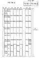
- Figs. 1 and 2 shows data formats in the present invention.
- Two channels of PCM signal having 12-bit words are arranged in two tracks.
- Fig. 1 shows the data format on the first track
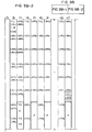
- Fig. 2 shows the data format on the second track.
- Numeral 1 denotes one symbol which consists of 8 bits
- numeral 2 denotes one block.
- one-word signal comprises two symbols, an upper symbol and a lower symbol.
- One block comprises 32 symbols and 128 blocks are recorded on one track.
- Numeral 3 denotes a first error detection and correction code Q and numeral 4 denotes a second error detection and correction code P.
- the number of data per revolution is 1920 words/channel. Since two recording heads are mounted on a cylinder, two tracks are recorded in one revolution. Accordingly, 1920 words/channel of data must be arranged on two tracks.
- the two channel of PCM signal are represented for the sake of convenience, by left and right channel signals L and R.
- the data formats on the first and second tracks, of the two channels of PCM signal having 16-bit words are shown in Figs. 9A and 9B.
- the detail is disclosed in U.S. Patent Application Serial No. 712,094 (European Patent Application No. 85103110.4 filed March 18, 1985) entitled "Rotary Head Type PCM Recording and Reproduction Method and System" by Hiroaki Takahashi, Masaharu Kobayashi, Takaharu Noguchi, Toshifumi Shibuya and Takao Arai on March 15, 1985 based on Japanese Patent Application No. 54-50915 filed on March 19, 1984, and assigned to the present assignee, the disclosure of which is incorporated herein by reference.
- the L channel of the PCM signal is represented by L 0 - L 1919 and the R channel of the PCM signal is represented by R 0 - R 1919 .
- Numerals indicate the order on the time sequence. Hatched areas are vacant areas.
- the two L and R channels of the PCM signal having 12-bit words two words (24 bits) of the L channel data and two words of the R channel data in the same order are converted to 3-symbol data.
- 8 bits of the 12-bit Li constitute one symbol
- 8 bits of 12-bit Ri constitute one symbol
- the remaining 4 bits of the 12-bit Li and the remaining 4 bits of the 12-bit Ri constitute one symbol.
- the L and R odd data and the L and R even data relative to L and R P PCM signals are arranged at spaced locations on different tracks. As shown in Fig.
- the even data are arranged in a first half of a first track and the odd data are arranged in a second half of a second track.
- the even data are arranged in a first half of the second track and the odd data are arranged in a second half of the first track.
- each region that is, the first half or the second half of each track
- data are arranged such that two consecutive symbols are arranged at close positions in the same block.
- the first symbol L and the second symbol L 0 /R 0 are arranged at the first and third positions in the first block
- the third symbol R 0 and the fourth symbol L 2 are arranged at the first and third positions in the third block, and so on. Since the data in one word or the data in one word of the L channel and one word of the R channel are included in the consecutive symbols, the error concealment capability is not affected even if errors occur in both symbols.
- the symbols of associated words are arranged at alternate positions in the block so that they may be contained in a second error detection/correction code sequence to be described later.
- the data thus arranged has the first error detection/correction code (parity symbol Q) 3 and the second error detection/correction code (parity symbol P) 4 added thereto so that errors can be detected and corrected during the reproduction.
- the first error detection/correction code 3 is first added, then the second error detection/correction code 4 is added.
- the first error detection/correction code (Q) 3 is added to the same symbol number of every four blocks (e.g. first symbol of Oth, 4th, 8th --- blocks) and it may be a Reed-Solomon code having a code length of 32 symbols and a minimum distance of 7.
- the second error detection/correction code (P) 4 is added to odd and even symbols of every two blocks and it may be a Reed-Solomon code having a code length of 32 symbols and a minimum distance of 5.
- Fig. 3 shows a track arrangement on a magnetic tape.
- Numeral 5 denotes the magnetic tape and numerals 6 and 7 denote first and second tracks scanned by the pair of rotary heads. The data are scattered in the two adjacent tracks, as shown in Fig. 1.
- Fig. 4 shows a method for converting the 12-bit PCM signal to the 8-bit symbols.
- the 12-bit data 8 of the L channel and the 12-bit data 9 of the R channel in the same order are converted to 3-symbol (8 bits/symbol) data 10 - 12.
- the symbol 10 consists of 8 high order bits of the data 8 of the L channel
- the symbol 12 consists of 8 high order bits of the data 9 of the R channel
- the symbol 11 consists of four low order bits of the data 8 of the L channel and four low order bits of the data 9 of the R channel.
- Fig. 5 shows a configuration of the PCM signal recording apparatus which records the PCM signal in accordance with the present invention.
- Numeral 20 denotes an input terminal to which the PCM signal is applied from a PCM signal source or a transmission line
- numeral 21 denotes a data bus
- numeral 22 denotes a data conversion circuit
- numerals 23 - 26 denote memories
- numeral 27 denotes a control circuit for the memories
- numeral 28 denotes an error detection/correction code addition circuit
- numeral 29 denotes a recording circuit
- numeral 30 denotes an amplifier
- numeral 31 denotes rotary heads.
- the 12-bit PCM signal applied to the input terminal 20 is converted to the 8-bit data by the data conversion circuit 22 and the 8-bit data is stored in the memories 23 - 25 through the data bus 21.
- the PCM signals stored in the memories 23 - 26 are supplied to the error detection/correction code addition circuit 28 where they are interleaved and the first error detection/correction code 3 and the second error detection/correction code 4 are added.
- the interleaved PCM signal having the parity symbols added thereto is supplied to the recording circuit 29 block by-block. In the recording circuit 29, a synchronization signal and sub-codes are added, and the signal is amplified by the amplifier 30 and recorded on the magnetic tape by the rotary heads 31.
- the memories 23 - 26 each has one track of memory capacity.
- the memories 23 and 25 store the data shown in Fig. 1 and the memories 24 and 26 store the data shown in Fig. 2.
- Those memories may be one or two memories divided into four memory areas.
- Fig. 6 illustrates the operation of the memories.
- Numeral 32 denotes input of data
- numeral 33 denotes addition of error correction/detection code
- numeral 34 denotes an output of data
- numeral 35 denotes a record signal to the magnetic tape.
- Numerals 23 - 26 inserted in the data/code series indicate the operating memories.
- the PCM signal outputted from the data conversion circuit 22 is stored in the memories 23 and 24 such that 1920 words of the data in the L channel and the R channel are stored in the memories 23 and 24, respectively, in one revolution (360°) of the rotary head 31.
- the addresses of the memories are controlled by the control circuit 27 so that the data are arranged as shown in Figs. 1 and 2.
- the data stored in the memories 23 and 24 have the error detection/correction codes added thereto during the next revolution and the data are recorded on the magnetic tape 5.
- the PCM signal supplied while the data stored in the memories 23 and 24 are recorded is stored in the memories 25 and 26, and recorded on the magnetic tape 5 during the next revolution.
- Fig. 7 shows the data conversion circuit 22. It converts the 12-bit signal to the 8-bit signal.
- Numerals 37 - 39 denote latch circuits and numerals 40 and 41 denote switching circuits. The operation is explained with reference to a timing chart of Fig. 8.
- the PCM signal supplied from the signal source and alternately arranged to the L and R channels by a multiplexor is supplied to the input terminal 20.
- the eight high order bits of the L channel PCM signal applied to the input terminal 20 is latched in the latch circuit 37, and four low order bits are latched in the latch circuit 38 through the switching circuit 40.
- the eight high order bits of the L channel latched in the latch circuit 37 is supplied to the output terminal 36 as the symbol 10.
- the eight high order bits of the R channel PCM signal applied to the input terminal 20 is latched in the latch circuit 37, and the four low order bits are latched in the latch circuit 39 through the switching circuit 40.
- the eight-bit data latched in the latch circuits 38 and 39 is supplied to the output terminal 36 as the symbol 11.
- the eight high order bits of the R channel latched in the latch circuit 37 is supplied to the output terminal 36 as the symbol 12.
- the 12-bit PCM signal can be converted to the 8-bit data with simple processing and the error concealment capability to the burst error is enhanced.
Abstract
Description
- The present invention relates to a PCM signal recording technique, and more particularly to method and apparatus for recording a PCM signal suitable for a rotary-head type PCM recorder.
- In the PCM recorder, as disclosed in Japanese Unexamined Patent Publication No. 58-173934 laid open on October 12, 1983 (Japanese Patent Application No. 57-55660 filed on April 3, 1982), a PCM signal (1 word) having a sampling frequency of 48 KHz or 44.1 KHz and the number of quantization bits of 16 is recorded by eight bits. (The eight bits are called one symbol). In the rotary head type PCM recorder for recording the PCM signal on a magnetic tape by the rotary head, the data sequence is recorded so that original PCM signals may be reconstructed in each track as disclosed in Japanese Unexamined Patent Publication No. 58-188314 laid open on November 2, 1983 (Japanese Patent Application No. 57-69915 filed on April 26, 1982).
- On the other hand, long time recording in which a recording time of the PCM signal to the recording medium is approximately two times as long as that of conventional recording may be attained by setting a sampling frequency of the signal to be recorded such as an audio signal to 32 KHz and non-linearly quantizing the signal by 12 bits. However, since one word consists of 12 bits, the conventional method of recording the signal by symbol cannot be used.
- A technical trend of rotary-head type digital audio tape recorder (R-DAT) is described in "DAT Meeting Activity" on pages 36 -42, particularly pages 40 -42 of ELECTRONICS, vol. 24, No. 10, 1984 published by EIAJ (Electronics Industries Association of Japan).
- It is an object of the present invention to provide method and apparatus for converting an input PCM signal having each word thereof comprised of a predetermined number of bits adaptively to a PCM signal recording scheme in which the word signal is recorded by a predetermined number of bits smaller than the number of bits of one word, as units of data processing.
- It is another object of the present invention to provide a PCM signal recording method suitable for a rotary-head type PCM recorder, in which the PCM signal having 12-bit words is converted to an 8-bit data so that it is applicable to a system in which the signal is processed by 8 bits in units, with the same error concealment capability as that attained when a PCM signal having 16-bit words is recorded.
- In accordance with one feature of the present invention, two words of PCM signals are converted to three symbols of data, including symbols each consisting of high order bits of each word, and a symbol consisting of low order bits of the respective words, and adjacent PCM signals are arranged as ODD data and EVEN data distant from each other on different tracks to facilitate processing of signals by 8 bits or by symbol and compensate for a burst error encountered in reproduction.
- In accordance with another feature of the present invention, two channels of sampled PCM signals are converted to 3-symbol data and recorded on a record medium by a plurality of rotary heads. A predetermined number of symbols of data which can be recorded on alternate tracks on the record medium are grouped into two groups corresponding to a first half and a second half of the PCM signals in the time sequence, and even symbol data corresponding to even PCM signals of the first half of the PCM signals and odd symbol data corresponding to odd PCM signals of the second half are recorded on one of the alternate tracks, and odd symbol data for odd PCM signals of the first half and even symbol data for even PCM signals of the second half are recorded on the other track, and the data terminates in units of alternate (pair) tracks. On the other hand, an error detection/correction code terminates in each track. In the first half and the second half of each track, the even symbol data and the odd symbol data of the PCM signals are arranged in this sequence or in the opposite sequence.
- In accordance with the present invention, the PCM signal having 12-bit words can be converted to an 8-bit signal by simple processing so that the signal can be applicable to the system in which the signal is processed by 8 bits. If one track of burst error or a burst error on a plurality of tracks up to one half of the track occurs, it does not appear as a burst error in the time sequence in reproduction and the error concealment capability is improved.
-
- Fig. 1 shows a data format on a first track in one embodiment of the present invention,
- Fig. 2 shows a data format on a second track,
- Fig. 3 shows a track arrangement on a magnetic tape,
- Fig. 4 illustrates a data conversion method,
- Fig. 5 shows a configuration of a PCM signal recording apparatus,
- Fig. 6 illustrates an operation of a memory,
- Fig. 7 shows a data conversion circuit,
- Fig. 8 shows a timing chart of the data conversion circuit, and
- Figs. 9A and 9B show data record formats corresponding to Figs. 1 and 2, respectively, when words need not be converted.
- One embodiment of the present invention is described with reference to Figs. 1 and 2.
- Figs. 1 and 2 shows data formats in the present invention. Two channels of PCM signal having 12-bit words are arranged in two tracks. Fig. 1 shows the data format on the first track, and Fig. 2 shows the data format on the second track. Numeral 1 denotes one symbol which consists of 8 bits and
numeral 2 denotes one block. Usually, one-word signal comprises two symbols, an upper symbol and a lower symbol. One block comprises 32 symbols and 128 blocks are recorded on one track.Numeral 3 denotes a first error detection and correction code Q andnumeral 4 denotes a second error detection and correction code P. - When a sampling frequency is 32 KHz (for 1 word = 12 bits) and a rotating speed of the rotary head is 1000 rpm, the number of data per revolution is 1920 words/channel. Since two recording heads are mounted on a cylinder, two tracks are recorded in one revolution. Accordingly, 1920 words/channel of data must be arranged on two tracks.
- The two channel of PCM signal are represented for the sake of convenience, by left and right channel signals L and R. The data formats on the first and second tracks, of the two channels of PCM signal having 16-bit words are shown in Figs. 9A and 9B. The detail is disclosed in U.S. Patent Application Serial No. 712,094 (European Patent Application No. 85103110.4 filed March 18, 1985) entitled "Rotary Head Type PCM Recording and Reproduction Method and System" by Hiroaki Takahashi, Masaharu Kobayashi, Takaharu Noguchi, Toshifumi Shibuya and Takao Arai on March 15, 1985 based on Japanese Patent Application No. 54-50915 filed on March 19, 1984, and assigned to the present assignee, the disclosure of which is incorporated herein by reference.
- In Fig. 1, the L channel of the PCM signal is represented by L0 - L1919 and the R channel of the PCM signal is represented by R0 - R1919. Numerals indicate the order on the time sequence. Hatched areas are vacant areas.
- In the two L and R channels of the PCM signal having 12-bit words, two words (24 bits) of the L channel data and two words of the R channel data in the same order are converted to 3-symbol data. 8 bits of the 12-bit Li constitute one symbol, 8 bits of 12-bit Ri constitute one symbol, and the remaining 4 bits of the 12-bit Li and the remaining 4 bits of the 12-bit Ri constitute one symbol. Of the three 8-bit data thus converted, the L and R odd data and the L and R even data relative to L and R P PCM signals are arranged at spaced locations on different tracks. As shown in Fig. 1, for the Oth - 959th 3-symbol data, the even data are arranged in a first half of a first track and the odd data are arranged in a second half of a second track. As shown in Fig. 2, for 960th - 1919th data, the even data are arranged in a first half of the second track and the odd data are arranged in a second half of the first track. By this arrangement, even if one track of burst error or a burst error on two tracks up to one half of the track takes place, a burst error does not appear on the time sequence in reproduction.
- In each region, that is, the first half or the second half of each track, data are arranged such that two consecutive symbols are arranged at close positions in the same block. For example, in the first half of the first track, the first symbol L and the second symbol L0/R0 are arranged at the first and third positions in the first block, the third symbol R0 and the fourth symbol L2 are arranged at the first and third positions in the third block, and so on. Since the data in one word or the data in one word of the L channel and one word of the R channel are included in the consecutive symbols, the error concealment capability is not affected even if errors occur in both symbols. The symbols of associated words are arranged at alternate positions in the block so that they may be contained in a second error detection/correction code sequence to be described later.
- The data thus arranged has the first error detection/correction code (parity symbol Q) 3 and the second error detection/correction code (parity symbol P) 4 added thereto so that errors can be detected and corrected during the reproduction. To add the error detection/correction codes, the first error detection/
correction code 3 is first added, then the second error detection/correction code 4 is added. The first error detection/correction code (Q) 3 is added to the same symbol number of every four blocks (e.g. first symbol of Oth, 4th, 8th --- blocks) and it may be a Reed-Solomon code having a code length of 32 symbols and a minimum distance of 7. The second error detection/correction code (P) 4 is added to odd and even symbols of every two blocks and it may be a Reed-Solomon code having a code length of 32 symbols and a minimum distance of 5. - Fig. 3 shows a track arrangement on a magnetic tape. Numeral 5 denotes the magnetic tape and
numerals - Fig. 4 shows a method for converting the 12-bit PCM signal to the 8-bit symbols. As described above, the 12-
bit data 8 of the L channel and the 12-bit data 9 of the R channel in the same order are converted to 3-symbol (8 bits/symbol) data 10 - 12. Thesymbol 10 consists of 8 high order bits of thedata 8 of the L channel, thesymbol 12 consists of 8 high order bits of thedata 9 of the R channel, and the symbol 11 consists of four low order bits of thedata 8 of the L channel and four low order bits of thedata 9 of the R channel. By this bit conversion format, the conversion is attained with a simple circuit as will be explained later. - Fig. 5 shows a configuration of the PCM signal recording apparatus which records the PCM signal in accordance with the present invention.
Numeral 20 denotes an input terminal to which the PCM signal is applied from a PCM signal source or a transmission line, numeral 21 denotes a data bus, numeral 22 denotes a data conversion circuit, numerals 23 - 26 denote memories, numeral 27 denotes a control circuit for the memories, numeral 28 denotes an error detection/correction code addition circuit, numeral 29 denotes a recording circuit, numeral 30 denotes an amplifier and numeral 31 denotes rotary heads. - The 12-bit PCM signal applied to the
input terminal 20 is converted to the 8-bit data by thedata conversion circuit 22 and the 8-bit data is stored in the memories 23 - 25 through thedata bus 21. The PCM signals stored in the memories 23 - 26 are supplied to the error detection/correctioncode addition circuit 28 where they are interleaved and the first error detection/correction code 3 and the second error detection/correction code 4 are added. The interleaved PCM signal having the parity symbols added thereto is supplied to therecording circuit 29 block by-block. In therecording circuit 29, a synchronization signal and sub-codes are added, and the signal is amplified by theamplifier 30 and recorded on the magnetic tape by the rotary heads 31. - The memories 23 - 26 each has one track of memory capacity. The
memories memories - Fig. 6 illustrates the operation of the memories.
Numeral 32 denotes input of data, numeral 33 denotes addition of error correction/detection code, numeral 34 denotes an output of data, and numeral 35 denotes a record signal to the magnetic tape. Numerals 23 - 26 inserted in the data/code series indicate the operating memories. The PCM signal outputted from thedata conversion circuit 22 is stored in thememories memories rotary head 31. The addresses of the memories are controlled by thecontrol circuit 27 so that the data are arranged as shown in Figs. 1 and 2. The data stored in thememories magnetic tape 5. The PCM signal supplied while the data stored in thememories memories magnetic tape 5 during the next revolution. - Fig. 7 shows the
data conversion circuit 22. It converts the 12-bit signal to the 8-bit signal. Numerals 37 - 39 denote latch circuits andnumerals - The PCM signal supplied from the signal source and alternately arranged to the L and R channels by a multiplexor is supplied to the
input terminal 20. The eight high order bits of the L channel PCM signal applied to theinput terminal 20 is latched in thelatch circuit 37, and four low order bits are latched in thelatch circuit 38 through the switchingcircuit 40. The eight high order bits of the L channel latched in thelatch circuit 37 is supplied to theoutput terminal 36 as thesymbol 10. Then, the eight high order bits of the R channel PCM signal applied to theinput terminal 20 is latched in thelatch circuit 37, and the four low order bits are latched in thelatch circuit 39 through the switchingcircuit 40. The eight-bit data latched in thelatch circuits output terminal 36 as the symbol 11. Finally, the eight high order bits of the R channel latched in thelatch circuit 37 is supplied to theoutput terminal 36 as thesymbol 12. - In accordance with the present embodiment, the 12-bit PCM signal can be converted to the 8-bit data with simple processing and the error concealment capability to the burst error is enhanced.
Claims (7)
said data conversion circuit generating the plurality of symbol data including symbols (10, 12) each consisting of the second number of high order bits of the PCM signals in the same time sequence and a symbol (11) having the second number of bits consisting of the remaining low order bits of the PCM signal;
said memory having a capacity to store data of a plurality of tracks;
said control circuit controlling so as to read out the stored symbol data by a data unit determined by a data quantity in a pair of first and second tracks and arrange the symbol data into first symbol data corresponding to a first half of the input channel PCM signal and even data, second symbol data corresponding to a second half and odd data, third symbol data corresponding to the second half and the even data and fourth symbol data corresponding to the first half and the odd data, and distribute the first and second symbol data to the first track and the third and fourth symbol data to the second track;
Applications Claiming Priority (2)
| Application Number | Priority Date | Filing Date | Title |
|---|---|---|---|
| JP216122/84 | 1984-10-17 | ||
| JP59216122A JPS6196574A (en) | 1984-10-17 | 1984-10-17 | Pcm signal recording method |
Publications (3)
| Publication Number | Publication Date |
|---|---|
| EP0178589A2 true EP0178589A2 (en) | 1986-04-23 |
| EP0178589A3 EP0178589A3 (en) | 1988-02-17 |
| EP0178589B1 EP0178589B1 (en) | 1992-01-02 |
Family
ID=16683595
Family Applications (1)
| Application Number | Title | Priority Date | Filing Date |
|---|---|---|---|
| EP85112832A Expired - Lifetime EP0178589B1 (en) | 1984-10-17 | 1985-10-10 | Method and apparatus for recording pcm signal |
Country Status (7)
| Country | Link |
|---|---|
| US (1) | US4704640A (en) |
| EP (1) | EP0178589B1 (en) |
| JP (1) | JPS6196574A (en) |
| KR (1) | KR900003595B1 (en) |
| CN (1) | CN85108275B (en) |
| CA (1) | CA1259402A (en) |
| DE (1) | DE3585073D1 (en) |
Cited By (9)
| Publication number | Priority date | Publication date | Assignee | Title |
|---|---|---|---|---|
| EP0220033A2 (en) * | 1985-10-11 | 1987-04-29 | Mitsubishi Denki Kabushiki Kaisha | A PCM recording and reproducing apparatus |
| EP0257991A2 (en) * | 1986-08-21 | 1988-03-02 | Sony Corporation | Apparatus for reproducing a digital signal |
| FR2617352A1 (en) * | 1987-06-26 | 1988-12-30 | Eduvision Sa | METHOD FOR ENCODING COMPUTER DATA FOR TRANSMISSION TO VIDEO STANDARDS, VIDEODISC USING SAID METHOD AND INTERFACE FOR OPERATING SUCH A VIDEODISK |
| EP0405885A1 (en) * | 1989-06-27 | 1991-01-02 | Matsushita Electric Industrial Co., Ltd. | Recording device and reproducing device |
| EP0449213A2 (en) * | 1990-03-27 | 1991-10-02 | Sanyo Electric Co., Ltd. | Interleave address generating circuit of digital audio tape recorder |
| EP0557130A3 (en) * | 1992-02-19 | 1995-12-13 | Mitsubishi Electric Corp | Data conversion method and recording/reproducing apparatus using the same |
| EP0797199A2 (en) * | 1996-03-18 | 1997-09-24 | Pioneer Electronic Corporation | Information record medium, apparatus for recording the same and apparatus for reproducing the same |
| EP0967603A2 (en) * | 1998-06-26 | 1999-12-29 | Kabushiki Kaisha Toshiba | Digital audio recording medium and reproducing apparatus thereof |
| EP1235221A2 (en) * | 1996-03-15 | 2002-08-28 | Pioneer Electronic Corporation | Information record medium, apparatus for recording the same and apparatus for reproducing the same |
Families Citing this family (13)
| Publication number | Priority date | Publication date | Assignee | Title |
|---|---|---|---|---|
| US4903148A (en) * | 1986-04-02 | 1990-02-20 | Matsushita Electric Industrial Co., Ltd. | Digital signal editing apparatus |
| JPS63187469A (en) * | 1987-01-30 | 1988-08-03 | Hitachi Ltd | Rotary head type recording and reproducing device |
| JPS63247975A (en) * | 1987-04-01 | 1988-10-14 | Hitachi Ltd | Pcm signal recorder |
| JP2624706B2 (en) * | 1987-09-30 | 1997-06-25 | 株式会社日立製作所 | PCM signal recording device |
| JP2550099B2 (en) * | 1987-09-30 | 1996-10-30 | 株式会社日立製作所 | PCM signal recording device |
| JP2512027B2 (en) * | 1987-11-04 | 1996-07-03 | 株式会社日立製作所 | PCM signal recording device |
| US5065260A (en) * | 1988-01-22 | 1991-11-12 | Sony Corporation | Method for recording/reproducing expanded digital signals in conventional format |
| JPH02105730A (en) * | 1988-10-14 | 1990-04-18 | Sony Corp | Data recording method |
| JP2693809B2 (en) * | 1989-03-17 | 1997-12-24 | シャープ株式会社 | Image recording and playback device |
| JPH04195863A (en) * | 1990-11-27 | 1992-07-15 | Sony Corp | Magnetic recording device |
| KR100256662B1 (en) * | 1996-03-21 | 2000-05-15 | 니시무로 타이죠 | Data arrangement method and medium for recording or transmitting data, and processing device thereof |
| US7054697B1 (en) * | 1996-03-21 | 2006-05-30 | Kabushiki Kaisha Toshiba | Recording medium and reproducing apparatus for quantized data |
| KR100588137B1 (en) * | 2005-06-20 | 2006-06-09 | 삼성전자주식회사 | Digital video data transmitting apparatus and display apparatus |
Citations (7)
| Publication number | Priority date | Publication date | Assignee | Title |
|---|---|---|---|---|
| US4224642A (en) * | 1977-05-18 | 1980-09-23 | Teac Corporation | PCM Recording and reproducing method providing for dropout compensation |
| GB2082426A (en) * | 1980-07-28 | 1982-03-03 | Sony Corp | Digital signal processing circuits |
| JPS58166516A (en) * | 1982-03-29 | 1983-10-01 | Mitsubishi Electric Corp | Pcm sound recording and reproducing device |
| JPS58185012A (en) * | 1982-04-23 | 1983-10-28 | Sony Corp | Recorder of pcm signal |
| JPS59177706A (en) * | 1983-03-25 | 1984-10-08 | Mitsubishi Electric Corp | Rotary head type pulse code modulation magnetic recording and reproducing device |
| EP0129224A1 (en) * | 1983-06-15 | 1984-12-27 | Hitachi, Ltd. | PCM signal recording/reproducing apparatus |
| EP0155664A2 (en) * | 1984-03-19 | 1985-09-25 | Hitachi, Ltd. | Rotary head type PCM recording and reproduction method and system |
Family Cites Families (1)
| Publication number | Priority date | Publication date | Assignee | Title |
|---|---|---|---|---|
| JPS5328409A (en) * | 1976-08-27 | 1978-03-16 | Mitsubishi Electric Corp | Pcm recorder/repeoducer |
-
1984
- 1984-10-17 JP JP59216122A patent/JPS6196574A/en active Granted
-
1985
- 1985-10-10 EP EP85112832A patent/EP0178589B1/en not_active Expired - Lifetime
- 1985-10-10 DE DE8585112832T patent/DE3585073D1/en not_active Expired - Lifetime
- 1985-10-11 CN CN85108275A patent/CN85108275B/en not_active Expired
- 1985-10-14 KR KR1019850007536A patent/KR900003595B1/en not_active IP Right Cessation
- 1985-10-15 US US06/787,447 patent/US4704640A/en not_active Expired - Lifetime
- 1985-10-16 CA CA000493110A patent/CA1259402A/en not_active Expired
Patent Citations (7)
| Publication number | Priority date | Publication date | Assignee | Title |
|---|---|---|---|---|
| US4224642A (en) * | 1977-05-18 | 1980-09-23 | Teac Corporation | PCM Recording and reproducing method providing for dropout compensation |
| GB2082426A (en) * | 1980-07-28 | 1982-03-03 | Sony Corp | Digital signal processing circuits |
| JPS58166516A (en) * | 1982-03-29 | 1983-10-01 | Mitsubishi Electric Corp | Pcm sound recording and reproducing device |
| JPS58185012A (en) * | 1982-04-23 | 1983-10-28 | Sony Corp | Recorder of pcm signal |
| JPS59177706A (en) * | 1983-03-25 | 1984-10-08 | Mitsubishi Electric Corp | Rotary head type pulse code modulation magnetic recording and reproducing device |
| EP0129224A1 (en) * | 1983-06-15 | 1984-12-27 | Hitachi, Ltd. | PCM signal recording/reproducing apparatus |
| EP0155664A2 (en) * | 1984-03-19 | 1985-09-25 | Hitachi, Ltd. | Rotary head type PCM recording and reproduction method and system |
Non-Patent Citations (3)
| Title |
|---|
| PATENT ABSTRACTS OF JAPAN, vol. 8, no. 1 (P-246)[1438], 6th January 1984; & JP-A-58 166 516 (MITSUBISHI) 01-10-1983 * |
| PATENT ABSTRACTS OF JAPAN, vol. 9, no. 33 (P-334)[1756], 13th February 1985; & JP-A-59 177 706 (MITSUBISHI) 08-10-1983 (Cat. A) * |
| PHILIPS TECHNICAL REVIEW, vol. 40, no. 6, 1982, pages 157-165, Eindhoven, NL; J.P.J. HEEMSKEERK et al.: "Compact disc: system aspects and modulation" * |
Cited By (23)
| Publication number | Priority date | Publication date | Assignee | Title |
|---|---|---|---|---|
| EP0220033A2 (en) * | 1985-10-11 | 1987-04-29 | Mitsubishi Denki Kabushiki Kaisha | A PCM recording and reproducing apparatus |
| EP0220033A3 (en) * | 1985-10-11 | 1987-12-23 | Mitsubishi Denki Kabushiki Kaisha | A pcm recording and reproducing apparatus |
| US4882638A (en) * | 1985-10-11 | 1989-11-21 | Mitsubishi Denki Kabushiki Kaisha | PCM recording and reproducing apparatus having common data frame construction for signal sources of varying quantization bit number |
| EP0257991A2 (en) * | 1986-08-21 | 1988-03-02 | Sony Corporation | Apparatus for reproducing a digital signal |
| EP0257991A3 (en) * | 1986-08-21 | 1989-05-10 | Sony Corporation | Methods of and apparatus for reproducing a digital signal |
| US4875111A (en) * | 1986-08-21 | 1989-10-17 | Sony Corporation | Apparatus for reproducing a digital signal |
| FR2617352A1 (en) * | 1987-06-26 | 1988-12-30 | Eduvision Sa | METHOD FOR ENCODING COMPUTER DATA FOR TRANSMISSION TO VIDEO STANDARDS, VIDEODISC USING SAID METHOD AND INTERFACE FOR OPERATING SUCH A VIDEODISK |
| EP0299818A1 (en) * | 1987-06-26 | 1989-01-18 | Eduvision S.A. | Method for coding information data for transmission in video norms, video disk for carrying out this method and interface of operating such a video disk |
| EP0405885A1 (en) * | 1989-06-27 | 1991-01-02 | Matsushita Electric Industrial Co., Ltd. | Recording device and reproducing device |
| EP0449213A3 (en) * | 1990-03-27 | 1993-06-16 | Sanyo Electric Co., Ltd. | Interleave address generating circuit of digital audio tape recorder |
| EP0449213A2 (en) * | 1990-03-27 | 1991-10-02 | Sanyo Electric Co., Ltd. | Interleave address generating circuit of digital audio tape recorder |
| EP0557130A3 (en) * | 1992-02-19 | 1995-12-13 | Mitsubishi Electric Corp | Data conversion method and recording/reproducing apparatus using the same |
| US5633632A (en) * | 1992-02-19 | 1997-05-27 | Mitsubishi Denki Kabushiki Kaisha | Data conversion method and apparatus imbedding pilot signal into converted data and reducing error propagation between datawords |
| SG85049A1 (en) * | 1992-02-19 | 2001-12-19 | Mitsubishi Electric Corp | Data conversion method and recording/reproducing apparatus using the same |
| EP1235221A2 (en) * | 1996-03-15 | 2002-08-28 | Pioneer Electronic Corporation | Information record medium, apparatus for recording the same and apparatus for reproducing the same |
| EP1235221A3 (en) * | 1996-03-15 | 2004-01-28 | Pioneer Electronic Corporation | Information record medium, apparatus for recording the same and apparatus for reproducing the same |
| EP0797199A2 (en) * | 1996-03-18 | 1997-09-24 | Pioneer Electronic Corporation | Information record medium, apparatus for recording the same and apparatus for reproducing the same |
| EP0797199A3 (en) * | 1996-03-18 | 1998-12-09 | Pioneer Electronic Corporation | Information record medium, apparatus for recording the same and apparatus for reproducing the same |
| EP0967603A3 (en) * | 1998-06-26 | 2000-02-23 | Kabushiki Kaisha Toshiba | Digital audio recording medium and reproducing apparatus thereof |
| US6580671B1 (en) | 1998-06-26 | 2003-06-17 | Kabushiki Kaisha Toshiba | Digital audio recording medium and reproducing apparatus thereof |
| EP0967603A2 (en) * | 1998-06-26 | 1999-12-29 | Kabushiki Kaisha Toshiba | Digital audio recording medium and reproducing apparatus thereof |
| US7050370B2 (en) | 1998-06-26 | 2006-05-23 | Kabushiki Kaisha Toshiba | Digital audio recording medium and reproducing apparatus thereof |
| US7269105B2 (en) | 1998-06-26 | 2007-09-11 | Kabushiki Kaisha Toshiba | Digital audio recording medium and reproducing apparatus thereof |
Also Published As
| Publication number | Publication date |
|---|---|
| EP0178589A3 (en) | 1988-02-17 |
| KR900003595B1 (en) | 1990-05-26 |
| DE3585073D1 (en) | 1992-02-13 |
| CN85108275B (en) | 1988-08-10 |
| CN85108275A (en) | 1986-04-10 |
| JPS6196574A (en) | 1986-05-15 |
| JPH0583986B2 (en) | 1993-11-30 |
| KR860003574A (en) | 1986-05-26 |
| US4704640A (en) | 1987-11-03 |
| EP0178589B1 (en) | 1992-01-02 |
| CA1259402A (en) | 1989-09-12 |
Similar Documents
| Publication | Publication Date | Title |
|---|---|---|
| US4704640A (en) | Method and apparatus for recording PCM signal | |
| US4866636A (en) | Method and apparatus for uniformly encoding data occurring with different word lengths | |
| US4630272A (en) | Encoding method for error correction | |
| EP0233783B1 (en) | Apparatus for recording and/or reproducing data | |
| EP0389006B1 (en) | Method and apparatus for recording a digital information signal | |
| EP0197560B1 (en) | Method and apparatus for recording pcm signals | |
| EP0155101B2 (en) | Method and apparatus for magnetic recording and reproducing | |
| US4646171A (en) | Apparatus for recording and/or reproducing digital information signal | |
| US4961204A (en) | PCM signal generating/reproducing apparatus | |
| EP0209141A2 (en) | PCM Signal recording and reproducing apparatus | |
| US4445216A (en) | System for defeating erroneous correction in a digital signal reproducing apparatus | |
| EP0323119B1 (en) | Method for transmitting digital data | |
| US4876616A (en) | Apparatus for reproducing a digital signal | |
| US5559644A (en) | Data recording/reproducing apparatus having a first error correcting code on both sides of a main data area of each azimuth track | |
| EP0411835B1 (en) | Decoder apparatus | |
| JP2840680B2 (en) | Playback device | |
| EP0488689B1 (en) | Multi-channel data recorder | |
| JPH05250814A (en) | Digital magnetic recording and reproducing device | |
| US5233480A (en) | Magnetic recorder/reproducer | |
| JPS62202363A (en) | Data reproducing device | |
| JPH0756736B2 (en) | Error correction code decoding device |
Legal Events
| Date | Code | Title | Description |
|---|---|---|---|
| PUAI | Public reference made under article 153(3) epc to a published international application that has entered the european phase |
Free format text: ORIGINAL CODE: 0009012 |
|
| 17P | Request for examination filed |
Effective date: 19851010 |
|
| AK | Designated contracting states |
Kind code of ref document: A2 Designated state(s): DE FR GB |
|
| PUAL | Search report despatched |
Free format text: ORIGINAL CODE: 0009013 |
|
| AK | Designated contracting states |
Kind code of ref document: A3 Designated state(s): DE FR GB |
|
| 17Q | First examination report despatched |
Effective date: 19880928 |
|
| GRAA | (expected) grant |
Free format text: ORIGINAL CODE: 0009210 |
|
| AK | Designated contracting states |
Kind code of ref document: B1 Designated state(s): DE FR GB |
|
| REF | Corresponds to: |
Ref document number: 3585073 Country of ref document: DE Date of ref document: 19920213 |
|
| ET | Fr: translation filed | ||
| PLBE | No opposition filed within time limit |
Free format text: ORIGINAL CODE: 0009261 |
|
| STAA | Information on the status of an ep patent application or granted ep patent |
Free format text: STATUS: NO OPPOSITION FILED WITHIN TIME LIMIT |
|
| 26N | No opposition filed | ||
| REG | Reference to a national code |
Ref country code: GB Ref legal event code: IF02 |
|
| PGFP | Annual fee paid to national office [announced via postgrant information from national office to epo] |
Ref country code: FR Payment date: 20040921 Year of fee payment: 20 |
|
| PGFP | Annual fee paid to national office [announced via postgrant information from national office to epo] |
Ref country code: GB Payment date: 20040923 Year of fee payment: 20 |
|
| PGFP | Annual fee paid to national office [announced via postgrant information from national office to epo] |
Ref country code: DE Payment date: 20041206 Year of fee payment: 20 |
|
| PG25 | Lapsed in a contracting state [announced via postgrant information from national office to epo] |
Ref country code: GB Free format text: LAPSE BECAUSE OF EXPIRATION OF PROTECTION Effective date: 20051009 |
|
| REG | Reference to a national code |
Ref country code: GB Ref legal event code: PE20 |