EP0189695B1 - Radio-communication system with slow frequency hopping and composite sequences allocation protocol - Google Patents
Radio-communication system with slow frequency hopping and composite sequences allocation protocol Download PDFInfo
- Publication number
- EP0189695B1 EP0189695B1 EP19850402521 EP85402521A EP0189695B1 EP 0189695 B1 EP0189695 B1 EP 0189695B1 EP 19850402521 EP19850402521 EP 19850402521 EP 85402521 A EP85402521 A EP 85402521A EP 0189695 B1 EP0189695 B1 EP 0189695B1
- Authority
- EP
- European Patent Office
- Prior art keywords
- sequences
- cells
- cell
- sequence
- frequency
- Prior art date
- Legal status (The legal status is an assumption and is not a legal conclusion. Google has not performed a legal analysis and makes no representation as to the accuracy of the status listed.)
- Expired
Links
Images


Classifications
-
- H—ELECTRICITY
- H04—ELECTRIC COMMUNICATION TECHNIQUE
- H04W—WIRELESS COMMUNICATION NETWORKS
- H04W16/00—Network planning, e.g. coverage or traffic planning tools; Network deployment, e.g. resource partitioning or cells structures
- H04W16/02—Resource partitioning among network components, e.g. reuse partitioning
- H04W16/12—Fixed resource partitioning
-
- H—ELECTRICITY
- H04—ELECTRIC COMMUNICATION TECHNIQUE
- H04B—TRANSMISSION
- H04B7/00—Radio transmission systems, i.e. using radiation field
- H04B7/24—Radio transmission systems, i.e. using radiation field for communication between two or more posts
- H04B7/26—Radio transmission systems, i.e. using radiation field for communication between two or more posts at least one of which is mobile
- H04B7/2628—Radio transmission systems, i.e. using radiation field for communication between two or more posts at least one of which is mobile using code-division multiple access [CDMA] or spread spectrum multiple access [SSMA]
- H04B7/2634—Radio transmission systems, i.e. using radiation field for communication between two or more posts at least one of which is mobile using code-division multiple access [CDMA] or spread spectrum multiple access [SSMA] for channel frequency control
-
- H—ELECTRICITY
- H04—ELECTRIC COMMUNICATION TECHNIQUE
- H04L—TRANSMISSION OF DIGITAL INFORMATION, e.g. TELEGRAPHIC COMMUNICATION
- H04L1/00—Arrangements for detecting or preventing errors in the information received
- H04L1/004—Arrangements for detecting or preventing errors in the information received by using forward error control
- H04L1/0041—Arrangements at the transmitter end
-
- H—ELECTRICITY
- H04—ELECTRIC COMMUNICATION TECHNIQUE
- H04L—TRANSMISSION OF DIGITAL INFORMATION, e.g. TELEGRAPHIC COMMUNICATION
- H04L1/00—Arrangements for detecting or preventing errors in the information received
- H04L1/004—Arrangements for detecting or preventing errors in the information received by using forward error control
- H04L1/0056—Systems characterized by the type of code used
- H04L1/0057—Block codes
-
- H—ELECTRICITY
- H04—ELECTRIC COMMUNICATION TECHNIQUE
- H04W—WIRELESS COMMUNICATION NETWORKS
- H04W16/00—Network planning, e.g. coverage or traffic planning tools; Network deployment, e.g. resource partitioning or cells structures
- H04W16/02—Resource partitioning among network components, e.g. reuse partitioning
Definitions
- the subject of the present invention is a slow frequency hopping and mixed sequence allocation protocol radio system.
- the system of the invention is of a type known as “multiple access with code distribution or abbreviated CDMA, (CDMA in English for“ Code Division Multiple Access ”). Furthermore, this system is of the“ jump ”type slow frequency “or abbreviated as SFL, (SFH in English for" Slow Frequency Hopping "). Before going into the detail of these CDMA / SFL systems it is useful to place them in the more general context of systems multiple access radio.
- the purpose of these protocols is to reduce interference between users through spatial, temporal or frequency distribution or by using coding techniques which make it possible to differentiate communications.
- the spatial distribution is obtained by cell division of the coverage area of the system.
- the capacity of a system is expressed in number of users per km 2 , we see that this parameter can always be improved provided that we accept a proportional increase in the number of fixed radio stations.
- Multiple access protocols must allow simultaneous communications while maintaining acceptable signal-to-interference ratios.
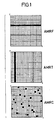
- a first family carries out Multiple Access to Frequency Distribution (AMRF), which means that separate frequency channels are assigned to the mobiles in the same neighborhood.
- AMRF Multiple Access to Frequency Distribution
- TDMA Multiple Time Distribution Access
- AMRC Multiple Access Code Distribution
- FIG. 1 schematically illustrates these three protocols by showing in a time frame (on the abscissa) -frequency (on the ordinate) the distribution of the intervals allocated to two users (black and striped intervals).
- SFR fast frequency hops
- SFL slow frequency hops
- the jump speed is higher than the data transmission rate, which means that for each binary item of information the modulator delivers several signals at different frequencies.
- the jump speed is lower than the data transmission rate. It is thus possible to transmit a few hundred binary elements with the same carrier.
- the useful speed of a channel can be of the order of a hundred kilobits / s, with frequency steps that last a few milliseconds.
- a large number (far greater than N) of random sequences, independent of each other, is generated from N frequency channels available, and such a sequence is allocated to each subscriber of the network, and this once and for all. This allocation is made, for example, at subscription.
- N the number of sequences
- This coding technique imposes an increased transmission rate, which can only be obtained with wider frequency spacing. For a given total radio band, the wider spacing of the channels has the effect of reducing the number thereof, and the rate of erasing of the stages is increased. A compromise must then be found between the redundancy rate and the erasure rate.
- the other management mode which is moreover closer to the invention which will be described, is the so-called orthogonal mode. It consists in generating a set of sequences which are strictly orthogonal to each other in the sense that there are no possible collisions on a level. The number of these sequences is equal to the number N of frequencies available. It is possible to assign these orthogonal sequences to the different communications as one assigns the N frequencies of a TDMA system or the N time intervals of a TDMA system. This is called "orthogonal" CDMA.
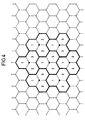
- FIG. 2 provides a better understanding of the principle of dividing radio coverage into cellular patterns.
- patterns with 7 hexagonal cells (according to a usual symbolization which should not be considered as a faithful representation of the real shape of the cells).
- Each cell is identified by a reference C 1 , C 2 , Cs .. Cs, C 7 , which represents the position of the cell in a pattern of size 7.
- C 1 , C 2 , Cs .. Cs, C 7 which represents the position of the cell in a pattern of size 7.
- We also sometimes speak of "color" of a cell to designate the position of the cell in a pattern. For example, all the C 5 cells have the same "color” in the sense that they all occupy the same position in the patterns (in this case the lowest position).
- the various patterns are also designated by Mi, M 2 , ...
- a set of sequences is assigned to each cell ((a total of 7 sets of sequences in the example illustrated), these sequences being orthogonal to one another in the same cell and in the cells of different colors.
- the same sequence sets are reused in the other patterns with the same distribution (cells of the same color work with the same sequence sets).
- this cell works with sequences which are orthogonal to each other in C 2 , but also orthogonal with any sequence of neighboring cells C s and C 7 of the same motif M i but also orthogonal with any sequence of the cell C 4 of the motif M 2 (since the sequences of C 4 -M 2 are identical to the sequences of C 4 -M i which are orthogonal to the sequences of C 2 -M 1 ) and with any sequence of C 5 and Ce cells of M 3 (since the sequences used in these cells are identical to the sequences used respectively in C 5 and Cs of M 1 ). There are therefore no possible collisions between a cell and its neighbors.
- the management mode advocated by the invention is “mixed” in the sense that it retains part of the orthogonal scenario in a cell and in its vicinity and that it is similar to the random scenario, by l use of a large number of pseudo-orthogonal sequences.
- the notion of independence of the codes is vague and does not make it possible to precisely define which sequences we will actually use and what the collision rate will be in different cells of the same number.
- the collision rate is zero in the same cell and in cells of different colors. But the rate can reach 1 for sequences used in cells of the same color belonging to different patterns (since, in these cells, the same sequence can be reused).
- the maximum collision rate is between 0 and 1 in cells of the same color belonging to different patterns.
- the invention clarifies this question by fixing the collision rate between a first sequence assigned to a cell and a second sequence assigned to another cell at a value less than if M is the number of frequencies actually used by the first and second sequences.
- M is the number of frequencies that must be used to constitute the two sequences.
- the two sequences can use sets of different frequencies, certain frequencies being found in the two sequences, but other frequencies being used only in one or the other of the sequences.
- M is at most equal to N, the total number of frequencies available in the system.
- the invention therefore relates to a CDMA / SFL communication system, this system being such that for a sequence assigned to a mobile station in a cell, the allocated sequences, in this cell or in a set of neighboring cells including this cell, to other mobile stations have, with the sequence in question, a zero collision rate, this system being characterized in that at least sequence allocated in the other cells, that is to say in the cells which are neither the cell in question nor the cells neighboring the cell in question has, with the sequence in question, a collision rate not zero but less than or equal to where M is the number of frequencies actually used in the two sequences.
- the cells are organized into groups called reuse patterns, each cell being identifiable by the position it occupies in a pattern, the maximum number of frequencies assigned to a cell being equal to P.
- the sequences used in cells of different positions have a zero collision rate and the sequences used in cells of the same position in different patterns have a collision rate less than
- the frequency allocation protocol adopted by the invention leads to a new property which is linked to what can be called the "diversity of jammers" which is added to the phenomenon of frequency diversity already mentioned. This point is worth stopping at because several advantages will ensue.
- the present invention therefore also relates to a system such as that which has been defined above, in which from digital information signals, coded signals having a certain redundancy rate are formed, these coded signals being organized in blocks. data, the data of a block being distributed over several frequency steps.
- redundancy In the first French patent cited above, we already find the idea of redundancy, but it is introduced in a completely different context which is that of allocation of random sequences. Furthermore, this redundancy consists of a repetition of the data while, in the invention, another redundant code is proposed and a block coding distributed over several stages.
- the redundancy introduced in the invention can call upon error detector and error correcting codes which are well known to those skilled in the art. Reed-Solomon codes seem to be particularly advantageous. The work of the Applicants has also shown that the optimal redundancy is generally between 2 and 3.
- the additional sequences thus introduced may have a collision rate k 'greater than the rate k used for telephony (the latter obviously being low and equal to 1 in general).
- Such additional sequences can be defined in large numbers as will be better understood later. They can possibly be allocated in a predetermined manner to the various subscribers of the system, like the sequences of the random CDMA systems mentioned above. However, of course, fixed stations can also assign them at the request of users, such as telephony sequences.
- the system can use several sets of sequences corresponding to information flows of several natures, the sequences being used in an incomplete manner and time multiplexed.
- a user can maintain several links in parallel by using simple multiplexing between different access codes.
- a realistic scheme consists of systematically using 6 of the 7 levels for speech and reserving 1 of 7 levels for other transmissions.
- the proportion of time allocated to these additional links makes it possible in fact to use several codes access for different types of exchanges (associated signaling, time synchronization, measurement of the levels received from several neighboring stations to prepare a cell change, broadcasting of messages, etc.).
- all the time intervals are used for different multiplexed data links (comprising in particular one or more call channels).
- the implicit framing of the information flows corresponding to the stages leads to simple multiplexing schemes between several communications of different nature. This results in great ease in signaling and controlling the network.
- the service offered to mobile subscribers is itself enriched by the possibility of establishing several simultaneous links in a mode compatible with the future integrated service digital network.
- each fixed station comprises several sectoral antennas, the station transmitting in only one sector at a time and receiving in only one sector at a time.
- each mobile station does not work at the same time in transmission and in reception.
- each mobile station works according to a cycle comprising a transmission level, a reception level and a rest level, the latter being used to change frequency, which makes it possible to benefit from a greater time.
- the reuse pattern is with 3 cells, which merge with 3 sectors.
- the advantages of the mixed scenario of the invention do not only concern the redundant internal coding, the reduction of the size of the patterns, the flexibility of management of the system, the possibility of multiservice systems, the distribution in time, all advantages which have just been emphasized, but still and finally allow an improvement in the spectral efficiency which is due to this. It is possible to implement the system of the invention in such a way that there is no effective transmission of the bearings during periods of silence of the communication. As soon as the interference phenomena occur through their average value, the real charge induced by a user is simply equal to the actual activity rate of his communication. It has been measured that the proportion of time when there is actually transmission of information on a voice channel is close to 40%.
- the CDMA / SFL radiotelephone systems accept a number of users 2.5 times greater in telephony, if one is able to detect all the periods of silence. This gain in activity, already significant for voice communications, becomes very significant for data transmissions which are by nature very impulsive.
- the system of the invention calls for total synchronization of the network which is obtained by broadcasting a time reference by the fixed stations.
- the slow frequency hopping technique is used with a step duration which is of the order of a millisecond.
- Speech is transmitted in digital form with a useful bit rate of around 16 kbit / s.
- rate here equal to 2
- a multiplying factor equal to three for distribution in the time between the 3 sectors and guard times between stages the gross throughput of the modulator is close to 150 kbit / s; the spacing between channels is then 150 kHz.
- a decisive advantage of the CDMA / SFL technique is the frequency diversity which makes it possible to combat selective fading and interference. With multipath propagation conditions, the quality of communication remains satisfactory regardless of the speed of movement of the mobiles.
- a type code (6,3) with redundancy rate equal to 2 thus makes it possible to obtain a rate of loss of speech blocks between 1% and 5% when the rate of loss of the levels is between 17% and 27%.
- a code (6,3) means that from 3 bytes of information we form 6 redundant bytes.
- Block coding with distribution of symbols on several levels is an essential complement to frequency diversity. It provides protection against interference and ultimately allows a higher rate of resource use (and therefore a greater number of mobiles per cell).
- This block is distributed over 3 frequency steps having a certain width (middle of the figure).
- FIG. 4 A system with 3 cells per motif, or 3 sectors, is shown diagrammatically in FIG. 4.
- the cells bear the references G, C 2 and C 3 .
- Such a system uses a set of fixed stations whose hardware characteristics are strictly identical (they all use the same frequency channels). They differ only in the sequence sets used and these can be changed by a simple revision of the software parameters. Without making any modification to the mobile terminals, it is possible to modify the sequence allocation rules to adapt to variable propagation and traffic conditions. For example, we can start with few radio sites and use a 1-pattern, without sectors, and then progress to a denser system with three-sector patterns.
- the number of telephone communications can be increased at the level of a cell by using an increasing number of orthogonal sequences and possibly using sequences which are not perfectly orthogonal but at low collision rate.
- the uniformity of the stations also makes it possible to envisage an automatic reconfiguration of the network by a simple adaptation of the transmission powers which increases the coverage area of the neighboring cells.
- the homogeneity of the network thus brings a certain number of advantages for management, linked in particular to the possibilities of reconfiguration of cellular patterns and the flexibility of evolution.
- the sequences used for voice communications differ from one motif to another. We thus obtain the property of diversity of jammers which makes it possible to use patterns of size as small as 3 while maintaining good quality of communication. If we use, in addition, mechanisms for detecting periods of silence (for telephony and for data transmissions), such a system in fact makes it possible to use radio resources only in proportion to actual activity. With an activity rate of less than 0.5 in telephony, we already obtain a significant advantage from the capacity point of view. For communications of an impulsive nature, this property becomes very profitable and it makes it possible to use pseudo-random sequences.
- Nk + 1 polynomials of degree k which define as many sequences of period (N-1), between which there are at most k collisions every N intervals, between any two sequences.
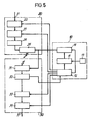
- FIG. 5 shows an example of a possible structure, which is moreover of a known type.
- the circuit shown comprises a transmission part 20, a reception part 30 and a set of common transmission-reception circuits 10.
- the common transmit-receive circuits 10 of the station include a sequence generator 11 controlled by a clock 12.
- the frequency hopping law generated by the generator 11 is determined as a function of the resources available. This management is ensured by a microprocessor 13.
- the output of this generator 11 is connected to a control input of a synthesizer 14 which is also connected to the clock 12.
- the output of the synthesizer delivers, for each level of the time law -current frequency, a different carrier frequency characteristic of the mobile and the network time.
- the transmission part includes an input 21 which receives the signal to be transmitted, an input circuit 22 whose output provides the signal to be transmitted in digital form and an encoding circuit 23, both controlled by the clock 12 of the assembly 10.
- the coding circuit 23 is intended to form blocks of digital data with redundancy, and to distribute these blocks over successive stages.
- the output of the coding circuit is connected to a modulator 24 which is connected to the input of a transmitter 25 which also receives, from the synthesizer 14, the carrier frequencies for the successive transmission stages.
- the reception part 30 includes a receiver 31, which receives the modulated signals. This receiver is controlled by the frequency synthesizer 14. The output of the receiver 31 is connected to the input of a demodulator 32 which supplies the rest of the demodulated digital data. The demodulator also provides a clock signal which is restored from the data received. This demodulator is therefore connected to the clock 12. The data is transmitted to a decoder 33 having a control input connected to the clock 12. An output circuit 34 restores the data on an output 35.
Description
La présente invention a pour objet un système de radiocommunications à sauts de fréquence lents et à protocole mixte d'attribution de séquences. Le système de l'invention est d'un type dit à "accès multiple à répartition dans les codes ou en abrégé AMRC, (CDMA en anglais pour "Code Division Multiple Access"). En outre, ce système est du type à "sauts de fréquence lents" ou en abrégé SFL, (SFH en anglais pour "Slow Frequency Hopping"). Avant d'entrer dans le détail de ces systèmes AMRC/SFL il n'est pas inutile de les situer dans le contexte plus général des systèmes radio à accès multiple.The subject of the present invention is a slow frequency hopping and mixed sequence allocation protocol radio system. The system of the invention is of a type known as “multiple access with code distribution or abbreviated CDMA, (CDMA in English for“ Code Division Multiple Access ”). Furthermore, this system is of the“ jump ”type slow frequency "or abbreviated as SFL, (SFH in English for" Slow Frequency Hopping "). Before going into the detail of these CDMA / SFL systems it is useful to place them in the more general context of systems multiple access radio.
On réunit sous le nom de protocole d'accès multiple un ensemble de procédures qui sont mises en oeuvre pour que plusieurs communications puissent coexister en utilisant une même ressource. Ces protocoles ont pour fonction de réduire les interférences entre utilisateurs grâce à une répartition spatiale, temporelle ou fréquentielle ou en utilisant des techniques de codage qui permettent de différencier les communications.One gathers under the name of multiple access protocol a set of procedures which are implemented so that several communications can coexist using the same resource. The purpose of these protocols is to reduce interference between users through spatial, temporal or frequency distribution or by using coding techniques which make it possible to differentiate communications.
La répartition dans l'espace est obtenue grâce à une division cellulaire de la zone de couverture du système. Ainsi, il est toujours possible de réduire la portée des émetteurs fixes et mobiles et de réutiliser le même spectre radio lorsque les émetteurs sont suffisamment éloignés pour que les interférences soient acceptables. Si la capacité d'un système s'exprime en nombre d'utilisateurs par km2, on voit que ce paramètre peut toujours être amélioré à condition d'accepter une augmentation proportionnelle du nombre de stations radio fixes. On préfère finalement évaluer l'efficacité spectrale d'un protocole en terme de nombre d'utilisateurs par cellule et par unité de bande radio.The spatial distribution is obtained by cell division of the coverage area of the system. Thus, it is always possible to reduce the range of fixed and mobile transmitters and to reuse the same radio spectrum when the transmitters are far enough apart for interference to be acceptable. If the capacity of a system is expressed in number of users per km 2 , we see that this parameter can always be improved provided that we accept a proportional increase in the number of fixed radio stations. Finally, we prefer to assess the spectral efficiency of a protocol in terms of the number of users per cell and per unit of radio band.
Les protocoles d'accès multiple doivent permettre des communications simultanées tout en maintenant des rapports signal sur interférences acceptables.Multiple access protocols must allow simultaneous communications while maintaining acceptable signal-to-interference ratios.
On peut distinguer plusieurs familles de protocoles suivant le mode de répartition des utilisateurs. Une première famille réalise un Accès Multiple à Répartition Fréquentielle (AMRF), ce qui signifie que l'on affecte des canaux fréquentiels distincts aux mobiles d'un même voisinage. Pour les systèmes organisés en motifs cellulaires, on retrouve les mêmes jeux de fréquences d'un motif à l'autre. Il y a donc réutilisation de la ressource fréquence dans la zone globale de couverture du système. La distance moyenne de réutilisation est égale à la distance séparant les centres de deux motifs adjacents.Several families of protocols can be distinguished according to the mode of distribution of users. A first family carries out Multiple Access to Frequency Distribution (AMRF), which means that separate frequency channels are assigned to the mobiles in the same neighborhood. For systems organized in cellular patterns, we find the same sets of frequencies from one pattern to another. There is therefore reuse of the frequency resource in the overall area of coverage of the system. The average reuse distance is equal to the distance between the centers of two adjacent patterns.
Il existe une deuxième famille de protocoles d'accès multiple où des utilisateurs voisins utilisent la même bande de fréquence. Ces protocoles ne sont utilisables que dans le cas des systèmes numériques. Pour éviter les interférences, les utilisateurs communiquent sur le canal partagé à des instants différents. On parle alors d'Accès Multiple à Répartition dans le Temps (AMRT).There is a second family of multiple access protocols where neighboring users use the same frequency band. These protocols can only be used in the case of digital systems. To avoid interference, users communicate on the shared channel at different times. This is known as Multiple Time Distribution Access (TDMA).
A côté des protocoles AMRF et AMRT, il existe une troisième technique qui réalise un protocole d'Accès Multiple à Répartition dans les Codes (AMRC). Les utilisateurs se distinguent alors par leur "code". Dans le cas particulier des sauts de fréquence lents le code est défini par la séquence des intervalles temps-fréquence qu'ils utilisent. Les échanges d'information sont possibles si l'émetteur et le récepteur changent de fréquence de façon synchrone. Pour cela le réseau est entièrement synchronisé par diffusion d'une référence de temps à partir de stations fixes vers des stations mobiles.In addition to the AMRF and AMRT protocols, there is a third technique which achieves a Multiple Access Code Distribution (AMRC) protocol. Users are distinguished by their "code". In the particular case of slow frequency hopping the code is defined by the sequence of time-frequency intervals they use. Information exchange is possible if the transmitter and the receiver change frequency synchronously. For this, the network is fully synchronized by broadcasting a time reference from fixed stations to mobile stations.
Avec ce dernier type d'accès multiple, on ne cherche plus à restreindre l'activité des utilisateurs dans une petite partie du domaine temps-fréquence. Au contraire, on accepte que tous les utilisateurs émettent sur l'ensemble de la ressource radio et on dit qu'il y a "étalement du spectre". On connaît depuis longtemps l'intérêt des techniques de modulation à étalement de spectre pour réaliser des transmissions en milieu très perturbé par le bruit ou les évanouissements. La diversité obtenue par l'utilisation d'une grande variété de ressources temps-fréquence peut en effet être mise à profit pour réaliser un codage correcteur efficace.With the latter type of multiple access, we no longer seek to restrict user activity in a small part of the time-frequency domain. On the contrary, we accept that all users transmit on the whole of the radio resource and we say that there is "spread spectrum". The interest in spread spectrum modulation techniques has long been known for performing transmissions in a medium very disturbed by noise or fading. The diversity obtained by the use of a large variety of time-frequency resources can indeed be used to achieve efficient corrective coding.
La figure 1 illustre schématiquement ces trois protocoles en montrant dans un repère temps (en abscisses)-fréquence (en ordonnées) la répartition des intervalles attribués à deux utilisateurs (intervalles noirs et rayés).FIG. 1 schematically illustrates these three protocols by showing in a time frame (on the abscissa) -frequency (on the ordinate) the distribution of the intervals allocated to two users (black and striped intervals).
On peut trouver une description de ces techniques dans un article de ON-CHING YUE intitulé "Spead Spectrum Mobile Radio, 1977-1982" publié dans la revue "IEEE Transactions on Vehicular Technology" vol VT-32, n°1, Février 1983, pp. 98-105.A description of these techniques can be found in an article by ON-CHING YUE entitled "Spead Spectrum Mobile Radio, 1977-1982" published in the review "IEEE Transactions on Vehicular Technology" vol VT-32,
En ce qui concerne la technique du saut de fréquence, il faut distinguer les sauts de fréquence rapides, en abrégé SFR (FFH en anglais pour "Fast Frequency Hopping") et les sauts de fréquence lents, en abrégé SFL (SFH pour "Slow Frequency Hopping"). En SFR la vitesse du saut est supérieure au taux de transmission des données, ce qui signifie que pour chaque élément binaire d'information le modulateur délivre plusieurs signaux à des fréquences différentes. En SFL, au contraire, la vitesse de saut est inférieure au taux de transmission des données. On peut ainsi transmettre quelques centaines d'éléments binaires avec la même porteuse. Pour fixer les idées, on peut dire qu'en SFL le débit utile d'une voie peut être de l'ordre de la centaine de kilobits/s, avec des paliers de fréquence qui durent quelques millisecondes.With regard to the frequency hopping technique, a distinction must be made between fast frequency hops, abbreviated as SFR (FFH for "Fast Frequency Hopping") and slow frequency hops, abbreviated as SFL (SFH for "Slow Frequency Hopping "). In SFR the jump speed is higher than the data transmission rate, which means that for each binary item of information the modulator delivers several signals at different frequencies. In SFL, on the contrary, the jump speed is lower than the data transmission rate. It is thus possible to transmit a few hundred binary elements with the same carrier. To fix ideas, we can say that in SFL the useful speed of a channel can be of the order of a hundred kilobits / s, with frequency steps that last a few milliseconds.
C'est donc dans cette dernière technique AMRC/SFL que se situe la présente invention.It is therefore in this latter CDMA / SFL technique that the present invention is situated.
Bien que les performances des systèmes de radiocommunications mettant en oeuvre le protocole AMRC/SFL déjà proposé donnent satisfaction à certains égards, leur efficacité spectrale (c'est-à-dire, comme indiqué plus haut, le nombre d'utilisateurs par cellule et par unité de bande radio) peut être améliorée, et c'est justement le but que vise l'invention. Pour comprendre comment ce problème est résolu il faut approfondir les techniques connues d'attribution des séquences aux différents utilisateurs.Although the performance of radiocommunication systems implementing the CDMA / SFL protocol already proposed is satisfactory in certain respects, their spectral efficiency (that is to say, as indicated above, the number of users per cell and per radio band unit) can be improved, and this is precisely the aim of the invention. To understand how this problem is solved, it is necessary to deepen the known techniques for assigning sequences to different users.
On connaît essentiellement deux modes d'attribution de ces fréquences que l'on qualifie généralement d'aléatoire et d'orthogonal.There are essentially two modes of allocation of these frequencies which are generally qualified as random and orthogonal.
Dans un mode de gestion aléatoire on engendre, à partir de N canaux de fréquences disponibles, un grand nombre (très supérieur à N) de séquences aléatoires, indépendantes les unes des autres et l'on alloue à chaque abonné du réseau une telle séquence, et cela une fois pour toutes. Cette allocation s'effectue par exemple à la prise d'abonnement. Comme le nombre de séquences est très grand, il n'est pas exclu que certains utilisateurs se trouvent ensemble, sur un même palier. Mais comme les séquences ont un caractère aléatoire, les interférences ne peuvent s'établir que de façon momentanée. Néanmoins, au fur et à mesure que la charge d'un tel système augmente, il est facile d'imaginer qu'il y a de plus en plus de collisions sur les paliers. Il est donc nécessaire d'introduire une certaine redondance en codant les informations utiles de façon à se protéger contre les effacements éventuels. Cette technique de codage impose un débit de transmission accru, qui ne peut être obtenu qu'avec un espacement des fréquences plus large. Pour une bande radio totale donnée, l'espacement plus large des canaux a pour effet d'en réduire le nombre, et le taux d'effacement des paliers se trouve augmenté. Il faut alors trouver un compromis entre le taux de redondance et le taux d'effacement.In a random management mode, a large number (far greater than N) of random sequences, independent of each other, is generated from N frequency channels available, and such a sequence is allocated to each subscriber of the network, and this once and for all. This allocation is made, for example, at subscription. As the number of sequences is very large, it is not excluded that certain users are together, on the same landing. But since the sequences are random, interference can only be established temporarily. However, as the load on such a system increases, it is easy to imagine that there are more and more collisions on the bearings. It is therefore necessary to introduce a certain redundancy by coding the useful information so as to protect against possible erasures. This coding technique imposes an increased transmission rate, which can only be obtained with wider frequency spacing. For a given total radio band, the wider spacing of the channels has the effect of reducing the number thereof, and the rate of erasing of the stages is increased. A compromise must then be found between the redundancy rate and the erasure rate.
On observera que dans un tel système, il n'y a pas véritablement de scénario d'attribution coordonné de la ressource temps-fréquence en fonction de la demande instantanée, puisque l'allocation est définitive. Cela simplifie évidemment la gestion au niveau des stations mais limite les performances. Il n'est pas non plus possible de construire des motifs de réutilisation comme dans un scénario AMRF. C'est l'ensemble de la couverture du système qui est traité par allocation prédéterminée d'un grand nombre de séquences.It will be observed that in such a system, there is no real scenario for the coordinated allocation of the time-frequency resource as a function of instantaneous demand, since the allocation is final. This obviously simplifies management at the station level but limits performance. It is also not possible to construct reuse patterns as in an AMRF scenario. The entire system coverage is processed by predetermined allocation of a large number of sequences.
Un tel scénario aléatoire est décrit dans la demande de brevet français n° 2529040 déposée le 18.06.1982 pour "Système de radiocommunications à sauts de fréquence, à redondance interpaliers" et dans la demande de brevet français 2527871 déposée le 27.05.82 pour "Système de radiocommunications à sauts de fréquence".Such a random scenario is described in the French patent application n ° 2529040 filed on 18.06.1982 for "Radiocommunication system with frequency hopping, with redundancy interpaliers" and in the French patent application 2527871 filed on 27.05.82 for "System frequency hopping radio communications ".
Le scénario aléatoire est également décrit dans un article de D.VERHULST et al. intitulé "Slow Frequency Hopping Multiple Access for Digital Cellular Radiotelephone" publié dans IEEE Journal on Selected Areas in Communications, vol SAC-2, n°4, juillet 1984, pp.563-574.The random scenario is also described in an article by D.VERHULST et al. entitled "Slow Frequency Hopping Multiple Access for Digital Cellular Radiotelephone" published in IEEE Journal on Selected Areas in Communications, vol SAC-2, n ° 4, July 1984, pp.563-574.
L'autre mode de gestion, qui est d'ailleurs plus proche de l'invention qui va être décrite, est le mode dit orthogonal. Il consiste à engendrer un ensemble de séquences qui sont rigoureusement orthogonales entre elles en ce sens qu'il n'y a pas de collisions possibles sur un palier. Le nombre de ces séquences est égal au nombre N de fréquences disponibles. Il est possible d'affecter ces séquences orthogonales aux différentes communications comme on affecte les N fréquences d'un système AMRF ou les N intervalles de temps d'un système AMRT. On parle alors d'AMRC "orthogonal".The other management mode, which is moreover closer to the invention which will be described, is the so-called orthogonal mode. It consists in generating a set of sequences which are strictly orthogonal to each other in the sense that there are no possible collisions on a level. The number of these sequences is equal to the number N of frequencies available. It is possible to assign these orthogonal sequences to the different communications as one assigns the N frequencies of a TDMA system or the N time intervals of a TDMA system. This is called "orthogonal" CDMA.
Au prix, il est vrai, d'une complexité accrue des appareils radio, on a obtenu un gain théorique par rapport à l'AMRF en raison de ce que l'effet des chemins multiples est différent sur chaque palier. Cela signifie que si, pour un palier de fréquence, on observe un évanouissement dû à des interférences entre chemins multiples, sur le palier suivant cet effet peut disparaître puisqu'alors la fréquence sera différente. On dit qu'il y a "diversité fréquentielle". Cette propriété facilite la protection par codage contre les évanouissements.At the cost, it is true, of an increased complexity of radio devices, we obtained a theoretical gain compared to AMRF because the effect of multiple paths is different on each level. This means that if, for a frequency level, we observe a fading due to interference between multiple paths, on the level following this effect may disappear since then the frequency will be different. It is said that there is "frequency diversity". This property facilitates coding protection against fading.
L'inconvénient du système orthogonal est qu'il ne peut conduire qu'à un nombre de séquences limité (égal au plus au nombre N de fréquences puisqu'il n'existe, à chaque instant, que N fréquences disponibles). La manière de choisir de telles séquences orthogonales fait appel à des notions qui sortiraient du cadre de la présente demande. Il suffit d'indiquer que ce problème peut se traiter à l'aide de la théorie des corps de Galois, qui sont des ensembles finis d'éléments. L'article de ON-CHING YUE cité plus haut évoque cette question, page 102.The drawback of the orthogonal system is that it can only lead to a limited number of sequences (at most equal to the number N of frequencies since there are, at each instant, only N frequencies available). The manner of choosing such orthogonal sequences calls upon concepts which would go beyond the scope of the present application. It suffices to indicate that this problem can be treated using the theory of Galois bodies, which are finite sets of elements. The ON-CHING YUE article cited above discusses this issue, page 102.
Dans un système AMRC orthogonal, les séquences ne sont pas allouées par avance aux utilisateurs mais attribuées au fur et à mesure des demandes de communication. Il en résulte qu'il y a blocage quand on atteint la capacité du système, c'est-à-dire quand N utilisateurs veulent communiquer simultanément, (alors que dans le mode de gestion aléatoire évoqué plus haut, il n'y a pas blocage mais dégradation progressive de la qualité des communications avec l'accroissement de la charge). C'est la raison pour laquelle, afin d'augmenter la capacité du système, on trouve dans l'AMRC orthogonal des motifs de réutilisation des ressources. L'ensemble de la couverture du système est formé de la juxtaposition de tels motifs. Quand on passe d'un motif au suivant, on retrouve les mêmes jeux de séquences.In an orthogonal CDMA system, the sequences are not allocated in advance to the users but allocated as and when communication requests are made. As a result, there is a blockage when the system capacity is reached, that is to say when N users want to communicate simultaneously, (while in the random management mode mentioned above, there is no blocking but progressive deterioration of the quality of communications with the increase in load). This is the reason why, in order to increase the capacity of the system, we find in the orthogonal CDMA reasons for the reuse of resources. The entire cover of the system is formed by the juxtaposition of such patterns. When we go from one motif to the next, we find the same sets of sequences.
La figure 2 permet de mieux comprendre le principe de division de la couverture radio en motifs cellulaires. Sur cette figure sont représentés des motifs à 7 cellules hexagonales (selon une symbolisation habituelle qui ne doit pas être considérée comme une représentation fidèle de la forme réelle des cellules). Chaque cellule est repérée par une référence C1, C2, Cs .. Cs, C7, qui représente la position de la cellule dans un motif de taille 7. On parle aussi parfois de "couleur" d'une cellule, pour désigner la position de la cellule dans un motif. Par exemple toutes les cellules C5 ont une même "couleur" en ce sens qu'elles occupent toutes une même position dans les motifs (en l'occurrence la position la plus basse). Les divers motifs sont par ailleurs désignés par Mi, M2,...Figure 2 provides a better understanding of the principle of dividing radio coverage into cellular patterns. In this figure are represented patterns with 7 hexagonal cells (according to a usual symbolization which should not be considered as a faithful representation of the real shape of the cells). Each cell is identified by a reference C 1 , C 2 , Cs .. Cs, C 7 , which represents the position of the cell in a pattern of size 7. We also sometimes speak of "color" of a cell, to designate the position of the cell in a pattern. For example, all the C 5 cells have the same "color" in the sense that they all occupy the same position in the patterns (in this case the lowest position). The various patterns are also designated by Mi, M 2 , ...
Dans un scénario orthogonal, on affecte un jeu de séquences à chaque cellule, (soit au total 7 jeux de séquences dans l'exemple illustré) ces séquences étant orthogonales entre elles dans une même cellule et dans les cellules de couleurs différentes. Les mêmes jeux de séquences sont réutilisés dans les autres motifs avec la même répartition (les cellules de même couleur travaillent avec les mêmes jeux de séquences).In an orthogonal scenario, a set of sequences is assigned to each cell ((a total of 7 sets of sequences in the example illustrated), these sequences being orthogonal to one another in the same cell and in the cells of different colors. The same sequence sets are reused in the other patterns with the same distribution (cells of the same color work with the same sequence sets).
On voit aisément que cette répartition cellulaire permet d'éviter tout conflit entre cellules proches : si l'on considère, par exemple, la cellule C2 du motif M1, cette cellule travaille avec des séquences qui sont orthogonales entre elles dans C2, mais également orthogonales avec toute séquence des cellules voisines Cs et C7 du même motif Mi mais également orthogonales avec toute séquence de la cellule C4 du motif M2 (puisque les séquences de C4-M2 sont identiques aux séquences de C4-Mi lesquelles sont orthogonales aux séquences de C2-M1) et avec toute séquence des cellules C5 et Ce de M3 (puisque les séquences utilisées dans ces cellules sont identiques aux séquences utilisées respectivement dans C5 et Cs de M1). Il n'y a donc pas de collisions possibles entre une cellule et ses voisines.We can easily see that this cellular distribution makes it possible to avoid any conflict between close cells: if we consider, for example, cell C 2 of the motif M 1 , this cell works with sequences which are orthogonal to each other in C 2 , but also orthogonal with any sequence of neighboring cells C s and C 7 of the same motif M i but also orthogonal with any sequence of the cell C 4 of the motif M 2 (since the sequences of C 4 -M 2 are identical to the sequences of C 4 -M i which are orthogonal to the sequences of C 2 -M 1 ) and with any sequence of C 5 and Ce cells of M 3 (since the sequences used in these cells are identical to the sequences used respectively in C 5 and Cs of M 1 ). There are therefore no possible collisions between a cell and its neighbors.
Malgré l'intérêt de ce système, un inconvénient apparaît losqu'on prend en compte, non pas seulement l'interaction d'une cellule avec des cellules adjacentes mais l'interaction d'une cellule avec des cellules éloignées non adjacentes. Dans le schéma de la figure 2, on voit par exemple que les deux cellules centrales C1, distantes de D (qui représente le pas du réseau) travaillent sur des jeux de séquences identiques. Bien qu'éloignées, ces deux cellules peuvent se gêner mutuellement. Chaque cellule d'une couleur particulière se trouvant entourée de 6 cellules de même couleur situées à une distance D, (par exemple les 6 cellules Ci des motifs M2 à M7), et ces 6 cellules travaillant avec le même jeu de fréquences, il résulte, en général, un brouillage continu par 6 émissions distantes.Despite the advantage of this system, a drawback appears when one takes into account not only the interaction of a cell with adjacent cells but the interaction of a cell with distant non-adjacent cells. In the diagram of FIG. 2, we see for example that the two central cells C 1 , distant from D (which represents the pitch of the network) work on sets of identical sequences. Although distant, these two cells can hinder each other. Each cell of a particular color being surrounded by 6 cells of the same color located at a distance D, (for example the 6 cells Ci of the patterns M 2 to M 7 ), and these 6 cells working with the same set of frequencies, it generally results in continuous interference by 6 distant transmissions.
C'est ce problème que se propose de résoudre l'invention en modifiant le mode d'attribution des séquences, tout en sauvegardant les avantages du scénario orthogonal au sein d'une cellule et dans le voisinage de celle-ci.It is this problem which the invention proposes to solve by modifying the mode of allocation of the sequences, while safeguarding the advantages of the orthogonal scenario within a cell and in the vicinity thereof.
On peut dire que le mode de gestion préconisé par l'invention est "mixte" en ce sens qu'il retient pour une part le scénario orthogonal dans une cellule et dans son voisinage et qu'il s'apparente au scénario aléatoire, par l'utilisation d'un grand nombre de séquences pseudo-orthogonales.We can say that the management mode advocated by the invention is "mixed" in the sense that it retains part of the orthogonal scenario in a cell and in its vicinity and that it is similar to the random scenario, by l use of a large number of pseudo-orthogonal sequences.
L'idée d'un scénario mixte a déjà été suggérée dans la littérature. C'est le cas, par exemple, dans l'article de M. MOULY et D. VERHULST publié dans l'Onde Electrique, mai-juin 1984, vol. 64, n°3, pp 22-28. Selon ce scénario, on affecte les codes aux mobiles qui veulent communiquer comme dans le mode orthogonal, mais en choisissant parmi un grand nombre de séquences qui ont les propriétés suivantes :
- - il n'y a pas de collision entre deux séquences utilisées dans une même cellule,
- - il n'y a pas de collision entre les cellules de numérotation différente dans le motif,
- - les codes utilisés dans des cellules différentes de même numéro sont indépendants les uns des autres.
- - there is no collision between two sequences used in the same cell,
- - there is no collision between the different numbering cells in the pattern,
- - the codes used in different cells of the same number are independent of each other.
En pratique, la notion d'indépendance des codes est floue et ne permet pas de définir avec précision quelles séquences on va réellement utiliser et quel sera le taux de collision dans des cellules différentes de même numéro. Dans un scénario orthogonal, le taux de collision est nul dans une même cellule et dans des cellules de couleurs différentes. Mais le taux peut atteindre 1 pour des séquences utilisées dans des cellules de même couleur appartenant à des motifs différents (puisque, dans ces cellules, la même séquence peut être réutilisée). Dans un scénario mixte, le taux de collision maximum est compris entre 0 et 1 dans des cellules de même couleur appartenant à des motifs différents.In practice, the notion of independence of the codes is vague and does not make it possible to precisely define which sequences we will actually use and what the collision rate will be in different cells of the same number. In an orthogonal scenario, the collision rate is zero in the same cell and in cells of different colors. But the rate can reach 1 for sequences used in cells of the same color belonging to different patterns (since, in these cells, the same sequence can be reused). In a mixed scenario, the maximum collision rate is between 0 and 1 in cells of the same color belonging to different patterns.
L'invention précise cette question en fixant le taux de collision entre une première séquence affectée à une cellule et une seconde séquence affectée à une autre cellule à une valeur inférieure à![]()
![]()
De toute manière, naturellement, M est au plus égal à N, nombre total de fréquences disponibles dans le système.In any case, naturally, M is at most equal to N, the total number of frequencies available in the system.
De façon précise, l'invention a donc pour objet un système de communication AMRC/SFL, ce système étant tel que pour une séquence attribuée à une station mobile dans une cellule, les séquences attribuées, dans cette cellule ou dans un ensemble de cellules voisines comprenant cette cellule, à d'autres stations mobiles ont, avec la séquence en question, un taux de collision nul, ce système étant caractérisé par le fait qu'au momoune séquence attribuée dans les autres cellules c'est-à-dire dans les cellules qui ne sont ni la cellule en question, ni les cellules voisines de la cellule en question a, avec la séquence en question, un taux de collision non nul mais inférieur ou égal à![]()
![]()
Dans un mode de réalisation avantageux les cellules sont organisées en groupes dits motifs de réutilisation, chaque cellule pouvant être repérée par la position qu'elle occupe dans un motif, le nombre maximum de fréquences attribué à une cellule étant égal à P. Dans ce cas, les séquences utilisées dans des cellules de positions différentes ont un taux de collision nul et les séquences utilisées dans des cellules de même position dans des motifs différents ont un taux de collision inférieur à![]()
![]()
Parmi les modes d'affectation possibles, on peut citer en particulier:
- a) la possibilité d'engendrer un nombre de séquences plus grand que le nombre de canaux fréquentiels. On obtient ainsi des codes plus ou moins "coordonnés" suivant le nombre de séquences nécessaires. Lorsque le nombre de séquences par cellule devient très grand (par exemple pour satisfaire un nombre élevé d'utilisateurs avec une faible activité), on tend vers un scénario comparable, du point de vue de la statistique des brouillages, au scénario aléatoire (si ce n'est qu'il peut faire appel à des motifs de réutilisation).
- b) la possibilité d'utiliser des motifs de réutilisation qui acceptent des interférences entre cellules de couleurs différentes. L'ensemble des brouilleurs se répartit alors sur un plus grand nombre de cellules pour obtenir un meilleur effet statistique.
- a) the possibility of generating a number of sequences greater than the number of frequency channels. One thus obtains more or less "coordinated" codes according to the number of sequences required. When the number of sequences per cell becomes very large (for example to satisfy a high number of users with low activity), one tends towards a scenario comparable, from the point of view of interference statistics, to the random scenario (if this is that it can appeal to reasons for re-use).
- b) the possibility of using reuse patterns that accept interference between cells of different colors. All the jammers are then distributed over a larger number of cells to obtain a better statistical effect.
Le protocole d'attribution de fréquence retenu par l'invention conduit à une propriété nouvelle qui est liée à ce qu'on peut appeler la "diversité de brouilleurs" qui s'ajoute au phénomène de diversité de fréquence déjà évoqué. Ce point mérite qu'on s'y arrête car plusieurs avantages vont en découler.The frequency allocation protocol adopted by the invention leads to a new property which is linked to what can be called the "diversity of jammers" which is added to the phenomenon of frequency diversity already mentioned. This point is worth stopping at because several advantages will ensue.
Pour concevoir un système AMRF ou AMRC orthogonal selon l'art antérieur, qui ait une bonne qualité de service, il faut construire des motifs assez grands en pensant aux cas les plus défavorables où un mobile est loin de sa base et où les autres utilisateurs des mêmes ressources radio sont dans une position particulièrement propice au brouillage. En d'autres termes, il ne sert à rien d'avoir un niveau moyen d'interférence assez faible s'il y a une probabilité non négligeable que les conditions de propagation respectives de différents utilisateurs favorisent le brouillage. Avec le système AMRC/SFL de l'invention on est dans une situation très différente car il y a un grand nombre de brouilleurs potentiels et les interférences viennent d'un nouveau groupe d'utilisateurs à chaque palier. On a affaire alors à un niveau moyen de brouillage.To design an orthogonal AMRF or CDMA system according to the prior art, which has a good quality of service, it is necessary to construct fairly large patterns, thinking of the most unfavorable cases where a mobile is far from its base and where the other users of the same radio resources are in a particularly favorable position for interference. In other words, there is no point in having a fairly low average level of interference if there is a significant probability that the respective propagation conditions of different users will favor interference. With the CDMA / SFL system of the invention, we are in a very different situation because there are a large number of potential jammers and the interference comes from a new group of users at each level. We are then dealing with an average level of interference.
Une première conséquence de cette diversité de brouilleurs est que la redondance qui peut être introduite dans les données d'information va s'avérer particulièrement efficace dans la lutte contre le brouillage, à condition de répartir les blocs de données sur plusieurs paliers. En effet, si un brouillage intervient sur un palier du fait d'une collision sur ce palier entre plusieurs utilisateurs appartenant à des cellules voisines, ce brouillage sera différent sur le palier suivant puisque les séquences des divers brouilleurs sont indépendantes de la séquence de l'utilisateur brouillé. L'entrelacement sur plusieurs paliers permettra donc, grâce aux données de redondance, de retrouver l'information perdue sur un palier. Ceci n'était pas le cas avec le scénario orthogonal puisqu'on pouvait retrouver à chaque palier les mêmes brouilleurs.A first consequence of this diversity of jammers is that the redundancy which can be introduced into the information data will prove to be particularly effective in the fight against interference, provided that the blocks of data are distributed over several levels. Indeed, if interference occurs on a level due to a collision on this level between several users belonging to neighboring cells, this interference will be different on the next level since the sequences of the various jammers are independent of the sequence of the scrambled user. Interleaving on several levels will therefore allow, thanks to the redundancy data, to find the information lost on a level. This was not the case with the orthogonal scenario since the same jammers could be found at each level.
La présente invention a donc également pour objet un système tel que celui qui a été défini plus haut, dans lequel à partir des signaux numériques d'information, on forme des signaux codés ayant un certain taux de redondance, ces signaux codés étant organisés en blocs de données, les données d'un bloc étant réparties sur plusieurs paliers de fréquence.The present invention therefore also relates to a system such as that which has been defined above, in which from digital information signals, coded signals having a certain redundancy rate are formed, these coded signals being organized in blocks. data, the data of a block being distributed over several frequency steps.
Dans le premier brevet français cité plus haut, on trouve déjà l'idée d'une redondance, mais celle-ci est introduite dans un tout autre contexte qui est celui d'une allocation de séquences aléatoires. Par ailleurs, cette redondance consiste en une répétition des données tandis que, dans l'invention, on propose un autre code redondant et un codage par blocs répartis sur plusieurs paliers.In the first French patent cited above, we already find the idea of redundancy, but it is introduced in a completely different context which is that of allocation of random sequences. Furthermore, this redundancy consists of a repetition of the data while, in the invention, another redundant code is proposed and a block coding distributed over several stages.
La redondance introduite dans l'invention peut faire appel à des codes détecteurs et correcteurs d'erreur qui sont bien connus de l'homme de l'art. Il semble que les codes de Reed-Solomon soient particulièrement avantageux. Les travaux des Demandeurs ont montré par ailleurs que la redondance optimale se situe en général entre 2 et 3.The redundancy introduced in the invention can call upon error detector and error correcting codes which are well known to those skilled in the art. Reed-Solomon codes seem to be particularly advantageous. The work of the Applicants has also shown that the optimal redundancy is generally between 2 and 3.
La diversité de brouilleurs associée au codage, permet un taux d'utilisation élevé. On peut alors utiliser des motifs de réutilisation petits. En particulier, comme on le verra par la suite, on peut utiliser des motifs composés seulement de quelques cellules, 4 ou moins de 4 par exemple, alors que dans les systèmes AMRC traditionnels, les motifs ont des tailles au moins égales à 7 et en général supérieures à 12.The diversity of jammers associated with coding allows a high rate of use. We can then use small reuse patterns. In particular, as will be seen later, it is possible to use patterns composed of only a few cells, 4 or less than 4 for example, while in traditional CDMA systems, the patterns have sizes at least equal to 7 and general above 12.
L'ensemble des propriétés qui précèdent permet d'adapter la configuration des motifs cellulaires et les règles d'attribution des séquences de fréquences en fonction des conditions d'utilisation du système. Cette flexibilité n'existait pas dans l'art antérieur des scénarii orthogonaux qui sont beaucoup plus contraignants.All of the above properties make it possible to adapt the configuration of cellular patterns and the rules for allocating frequency sequences according to the conditions of use of the system. This flexibility did not exist in the prior art orthogonal scenarios which are much more restrictive.
Selon encore un autre aspect de l'invention, on peut superposer au schéma qui vient d'être décrit, et qui concerne les communications téléphoniques, un autre schéma, moins exigeant en ce qui concerne les collisions entre séquences et qui sert à la transmission de données diverses. On aboutit alors à un système multiservice qui permet de transmettre non seulement la parole mais également les signaux de signalisation ou des données.According to yet another aspect of the invention, one can superimpose on the diagram which has just been described, and which relates to telephone communications, another diagram, less demanding as regards collisions between sequences and which is used for the transmission of miscellaneous data. This then leads to a multiservice system which makes it possible to transmit not only speech but also signaling signals or data.
Les séquences supplémentaires ainsi introduites pourront avoir un taux de collision k' plus grand que le taux k retenu pour la téléphonie (ce dernier étant évidemment faible et égal à 1 en général). De telles séquences supplémentaires peuvent être définies en grand nombre comme on le comprendra mieux par la suite. Elles peuvent éventuellement être allouées de manière prédéterminée aux divers abonnés du système, comme les séquences des systèmes AMRC aléatoires évoqués plus haut. Mais, naturellement, les stations fixes peuvent aussi les attribuer à la demande des utilisateurs, comme des séquences de téléphonie.The additional sequences thus introduced may have a collision rate k 'greater than the rate k used for telephony (the latter obviously being low and equal to 1 in general). Such additional sequences can be defined in large numbers as will be better understood later. They can possibly be allocated in a predetermined manner to the various subscribers of the system, like the sequences of the random CDMA systems mentioned above. However, of course, fixed stations can also assign them at the request of users, such as telephony sequences.
Selon encore un autre aspect de l'invention le système peut utiliser plusieurs jeux de séquences correspondant à des flux d'informations de plusieurs natures, les séquences étant utilisées de manière incomplète et multiplexées temporellement.According to yet another aspect of the invention, the system can use several sets of sequences corresponding to information flows of several natures, the sequences being used in an incomplete manner and time multiplexed.
Un utilisateur peut maintenir plusieurs liaisons en parallèle en utilisant un multiplexage simple entre différents codes d'accès. Pendant une communication téléphonique, un schéma réaliste consiste à utiliser systématiquement 6 paliers sur 7 pour la parole et à réserver 1 palier sur 7 pour d'autres transmissions.A user can maintain several links in parallel by using simple multiplexing between different access codes. During a telephone call, a realistic scheme consists of systematically using 6 of the 7 levels for speech and reserving 1 of 7 levels for other transmissions.
La proportion du temps alloué à ces liaisons complémentaires permet d'utiliser en fait plusieurs codes d'accès pour différents types d'échanges (signalisation associée, synchronisation horaire, mesure des niveaux reçus de plusieurs stations voisines pour préparer un changement de cellule, diffusion de messages, etc...). Dans les phases de veille où le mobile n'a pas de communications vocales, tous les intervalles de temps sont utilisés pour différentes liaisons de données multiplexées (comprenant en particulier un ou plusieurs canaux d'appel).The proportion of time allocated to these additional links makes it possible in fact to use several codes access for different types of exchanges (associated signaling, time synchronization, measurement of the levels received from several neighboring stations to prepare a cell change, broadcasting of messages, etc.). In the standby phases where the mobile has no voice communications, all the time intervals are used for different multiplexed data links (comprising in particular one or more call channels).
Le tramage implicite des flux d'information correspondant aux paliers conduit à des schémas de multiplexage simples entre plusieurs communications de nature différente. Il en résulte une grande facilité pour la signalisation et le contrôle du réseau. Le service offert aux abonnés mobiles est lui même enrichi par la possibilité d'établir plusieurs liaisons simultanées dans un mode compatible avec le futur réseau numérique à intégration de services.The implicit framing of the information flows corresponding to the stages leads to simple multiplexing schemes between several communications of different nature. This results in great ease in signaling and controlling the network. The service offered to mobile subscribers is itself enriched by the possibility of establishing several simultaneous links in a mode compatible with the future integrated service digital network.
Il existe une autre propriété particulièrement intéressante qui tient en ceci. Il est possible de faire travailler le système aussi selon le protocole d'accès multiple à répartition dans le temps (AMRT), permettant ainsi à plusieurs stations mobiles en communication avec la même station fixe d'utiliser la même séquence mais avec des paliers de fréquence disjoints.There is another particularly interesting property which is due to this. It is possible to make the system work also according to the time division multiple access protocol (TDMA), thus allowing several mobile stations in communication with the same fixed station to use the same sequence but with frequency steps disjointed.
Dans un mode particulier de réalisation de cette variante, chaque station fixe comprend plusieurs antennes sectorielles, la station émettant dans un seul secteur à la fois et recevant dans un seul secteur à la fois.In a particular embodiment of this variant, each fixed station comprises several sectoral antennas, the station transmitting in only one sector at a time and receiving in only one sector at a time.
De préférence, chaque station mobile ne travaille pas en même temps en émission et en réception.Preferably, each mobile station does not work at the same time in transmission and in reception.
De préférence encore, chaque station mobile travaille selon un cycle comprenant un palier d'émission, un palier de réception et un palier de repos, ce dernier étant utilisé pour changer de fréquence, ce qui permet de bénéficier d'un temps plus grand.Preferably still, each mobile station works according to a cycle comprising a transmission level, a reception level and a rest level, the latter being used to change frequency, which makes it possible to benefit from a greater time.
Enfin, selon encore un autre mode de réalisation, qui rassemble les dispositions précédentes, le motif de réutilisation est à 3 cellules, qui se confondent avec 3 secteurs.Finally, according to yet another embodiment, which brings together the preceding provisions, the reuse pattern is with 3 cells, which merge with 3 sectors.
Si cette répartition dans le temps entre n secteurs est mise à profit pour réaliser des motifs de réutilisation d'ordre n, toutes les stations de base utilisent le même ensemble de canaux fréquentiels. Cela permet l'introduction progressive des stations sans révision de l'ensemble du réseau. Cela permet aussi d'envisager une reconfiguration dynamique (et automatique) en cas de défaillance d'une station fixe par simple contrôle de la puissance des émissions.If this time distribution between n sectors is used to achieve n-order reuse patterns, all the base stations use the same set of frequency channels. This allows the gradual introduction of stations without overhauling the entire network. This also makes it possible to envisage a dynamic (and automatic) reconfiguration in the event of the failure of a fixed station by simple control of the power of the transmissions.
Les avantages du scénario mixte de l'invention ne concernent pas seulement le codage redondant in- terpalier, la réduction de la taille des motifs, la souplesse de gestion du système, la possibilité de systèmes multiservices, la répartition dans le temps, tous avantages qui viennent d'être soulignés, mais permettent encore et enfin une amélioration de l'efficacité spectrale qui tient en ceci. Il est possible de réaliser le système de l'invention de telle manière qu'il n'y ait pas transmission effective des paliers dans les périodes de silence de la communication. Dès lors que les phénomènes d'interférence interviennent par leur valeur moyenne, la charge réelle induite par un utilisateur est simplement égale au taux d'activité réel de sa communication. Il a été mesuré que la proportion du temps où il y a effectivement transmission d'informations sur un canal vocal est voisin de 40%. Il en résulte que les systèmes ra- diotéléphoniques AMRC/SFL selon l'invention acceptent un nombre d'utilisateurs 2,5 fois plus grand en téléphonie, si l'on est capable de détecter toutes les périodes de silence. Ce gain d'activité, déjà important pour les communications vocales, devient très important pour les transmissions de données qui sont par nature très impulsives.The advantages of the mixed scenario of the invention do not only concern the redundant internal coding, the reduction of the size of the patterns, the flexibility of management of the system, the possibility of multiservice systems, the distribution in time, all advantages which have just been emphasized, but still and finally allow an improvement in the spectral efficiency which is due to this. It is possible to implement the system of the invention in such a way that there is no effective transmission of the bearings during periods of silence of the communication. As soon as the interference phenomena occur through their average value, the real charge induced by a user is simply equal to the actual activity rate of his communication. It has been measured that the proportion of time when there is actually transmission of information on a voice channel is close to 40%. As a result, the CDMA / SFL radiotelephone systems according to the invention accept a number of users 2.5 times greater in telephony, if one is able to detect all the periods of silence. This gain in activity, already significant for voice communications, becomes very significant for data transmissions which are by nature very impulsive.
De toutes façons on comprendra mieux l'invention après la description qui va suivre d'un exemple de réalisation qui est donné à titre explicatif et nullement limitatif. Cette description se réfère à des dessins annexés sur lesquels :
- - la figure 1, déjà décrite, illustre trois variétés de protocoles d'accès multiple,
- - la figure 2, déjà décrite, illustre un réseau à motifs cellulaires selon l'art antérieur,
- - la figure 3 représente un exemple de schéma de codage,
- - la figure 4 représente un motif à 3 cellules selon un mode particulier de réalisation de l'invention,
- - la figure 5 montre un schéma synoptique d'un émetteur-récepteur selon un mode particulier de réalisation de l'invention.
- FIG. 1, already described, illustrates three varieties of multiple access protocols,
- FIG. 2, already described, illustrates a network with cellular patterns according to the prior art,
- FIG. 3 represents an example of a coding scheme,
- FIG. 4 represents a pattern with 3 cells according to a particular embodiment of the invention,
- - Figure 5 shows a block diagram of a transceiver according to a particular embodiment of the invention.
Dans la description qui suit, on énumère les caractéristiques et avantages les plus importants, concernant le scénario d'affectation des séquences selon l'invention et plus particulièrement ceux d'un système à trois secteurs.In the description which follows, the most important characteristics and advantages are listed, concerning the sequence assignment scenario according to the invention and more particularly those of a three-sector system.
De manière générale, tout d'abord, le système de l'invention fait appel à une synchronisation totale du réseau qui est obtenue par diffusion d'une référence de temps par les stations fixes. La technique de sauts de fréquence lents est utilisée avec une durée de palier qui est de l'ordre de la milliseconde. La parole est transmise sous forme numérique avec un débit utile voisin de 16 kbit/s. En tenant compte de la redondance du codage de canal (taux ici égal à 2), de la capacité complémentaire nécessaire pour la signalisation (et éventuellement les transmissions de données en cours de communication), d'un facteur multiplicatif égal à trois pour la répartition dans le temps entre les 3 secteurs et des temps de garde entre paliers, le débit brut du modulateur est voisin de 150 kbit/s ; l'espacement entre canaux est alors de 150 kHz.In general, first of all, the system of the invention calls for total synchronization of the network which is obtained by broadcasting a time reference by the fixed stations. The slow frequency hopping technique is used with a step duration which is of the order of a millisecond. Speech is transmitted in digital form with a useful bit rate of around 16 kbit / s. Taking into account the redundancy of the channel coding (rate here equal to 2), the additional capacity necessary for signaling (and possibly data transmissions during communication), a multiplying factor equal to three for distribution in the time between the 3 sectors and guard times between stages, the gross throughput of the modulator is close to 150 kbit / s; the spacing between channels is then 150 kHz.
Comme indiqué plus haut, un avantage déterminant de la technique AMRC/SFL, est la diversité de fréquence qui permet de lutter contre les évanouissements selectifs et les interférences. Avec des conditions de propagation à chemins multiples, la qualité de communication reste satisfaisante quelle que soit la vitesse de déplacement des mobiles.As indicated above, a decisive advantage of the CDMA / SFL technique is the frequency diversity which makes it possible to combat selective fading and interference. With multipath propagation conditions, the quality of communication remains satisfactory regardless of the speed of movement of the mobiles.
Pour se protéger contre les effacements de paliers (dûs aux interférences et aux évanouissements) on tire profit de la double diversité obtenue selon l'invention en utilisant un codage par bloc de type Reed-Solomon. Un code de type (6,3) avec taux de redondance égal à 2 permet ainsi d'obtenir un taux de perte de blocs de parole entre 1% et 5% lorsque le taux de perte des paliers est compris entre 17% et 27%. On sait qu'un code (6,3) signifie qu'à partir de 3 octets d'informations on forme 6 octets redondants.To protect against erasing of bearings (due to interference and fading), advantage is taken of the double diversity obtained according to the invention by using a block coding of the Reed-Solomon type. A type code (6,3) with redundancy rate equal to 2 thus makes it possible to obtain a rate of loss of speech blocks between 1% and 5% when the rate of loss of the levels is between 17% and 27%. We know that a code (6,3) means that from 3 bytes of information we form 6 redundant bytes.
Le codage par bloc avec distribution des symboles sur plusieurs paliers est un complément indispensable de la diversité de fréquence. Il apporte une protection contre les interférences et il permet finalement d'avoir un taux d'utilisation des ressources plus élevé (et donc un plus grand nombre de mobiles par cellule).Block coding with distribution of symbols on several levels is an essential complement to frequency diversity. It provides protection against interference and ultimately allows a higher rate of resource use (and therefore a greater number of mobiles per cell).
La figure 3 montre le schéma de principe de ce codage, dans le cas particulier suivant :
- - la durée des paliers est de 3 ms,
- - le débit utile pour la parole est de 16 kbit/s,
- - la longueur d'un bloc élémentaire d'information est de 18 ms et correspond au temps de transmission de 6 paliers,
- - un bloc contient 36 octets qui forment 12 groupes de 3 octets avant codage,
- - on utilise des codes (6,3)
qui transforment 3 octets utiles en 6 octets redondants, - - pour chacun des 12 mots de code, on répartit les 6 cotets après codage sur les 6 paliers.
- - the duration of the steps is 3 ms,
- - the useful bit rate for speech is 16 kbit / s,
- - the length of an elementary block of information is 18 ms and corresponds to the transmission time of 6 steps,
- - a block contains 36 bytes which form 12 groups of 3 bytes before coding,
- - we use codes (6,3) which transform 3 useful bytes into 6 redundant bytes,
- - for each of the 12 code words, the 6 cotets after coding are distributed over the 6 levels.
Sur la partie supérieure est représenté un bloc de données sans redondance (taux R=1). Ce bloc est réparti sur 3 paliers de fréquence ayant une certaine largeur (milieu de la figure). Selon l'invention, le bloc de données est codé avec une redondance 2 (R=2) et le bloc codé est réparti sur 6 paliers dont la largeur en fréquence est double (partie inférieure). Le nombre de canaux disponibles est donc divisé par 2.On the upper part is represented a data block without redundancy (rate R = 1). This block is distributed over 3 frequency steps having a certain width (middle of the figure). According to the invention, the data block is coded with redundancy 2 (R = 2) and the coded block is distributed over 6 steps whose frequency width is double (lower part). The number of available channels is therefore divided by 2.
Dans un tel système, il y a effacement de 18 ms de parole si et seulement si plus de trois paliers sont effacés.In such a system, there is an erasure of 18 ms of speech if and only if more than three stages are erased.
Un système à 3 cellules par motif, ou 3 secteurs, est représenté schématiquement sur la figure 4. Les cellules portent les références G, C2 et C3. Un tel système fait appel à un ensemble de stations fixes dont les caractéristiques matérielles sont rigoureusement identiques (elles utilisent toutes les mêmes canaux fréquentiels). Elles ne diffèrent que par les jeux de séquences utilisés et ceux-ci peuvent être changés par une simple révision des paramètres du logiciel. Sans apporter la moindre modification aux terminaux mobiles, il est possible de faire évoluer les règles d'attribution des séquences pour s'adapter à des conditions de propagation et de trafic variables. Par exemple, on peut commencer avec peu de sites radio et utiliser un motif à 1, sans secteur, pour évoluer ensuite vers un système plus dense avec des motifs à trois secteurs. Si les conditions de propagation limitent a priori les interférences entre mobiles distants, on peut augmenter le nombre de communications téléphoniques au niveau d'une cellule en utilisant un nombre de séquences orthogonales de plus en plus grand et en utilisant éventuellement des séquences non parfaitement orthogonales mais à faible taux de collision. Lorsqu'une station tombe en panne, l'uniformité des stations permet aussi d'envisager une reconfiguration automatique du réseau par une simple adaptation des puissances d'émission qui augmente la zone de couverture des cellules voisines.A system with 3 cells per motif, or 3 sectors, is shown diagrammatically in FIG. 4. The cells bear the references G, C 2 and C 3 . Such a system uses a set of fixed stations whose hardware characteristics are strictly identical (they all use the same frequency channels). They differ only in the sequence sets used and these can be changed by a simple revision of the software parameters. Without making any modification to the mobile terminals, it is possible to modify the sequence allocation rules to adapt to variable propagation and traffic conditions. For example, we can start with few radio sites and use a 1-pattern, without sectors, and then progress to a denser system with three-sector patterns. If the propagation conditions limit a priori the interference between distant mobiles, the number of telephone communications can be increased at the level of a cell by using an increasing number of orthogonal sequences and possibly using sequences which are not perfectly orthogonal but at low collision rate. When a station breaks down, the uniformity of the stations also makes it possible to envisage an automatic reconfiguration of the network by a simple adaptation of the transmission powers which increases the coverage area of the neighboring cells.
L'homogénéité du réseau apporte ainsi un certain nombre d'avantages pour la gestion, liés notamment aux possibilités de reconfiguration des motifs cellulaires et à la souplesse d'évolution.The homogeneity of the network thus brings a certain number of advantages for management, linked in particular to the possibilities of reconfiguration of cellular patterns and the flexibility of evolution.
Les séquences utilisées pour les communications vocales sont différentes d'un motif à l'autre. On obtient ainsi la propriété de diversité de brouilleurs qui rend possible l'utilisation de motifs de taille aussi petite que 3 en maintenant une bonne qualité de communication. Si on utilise, en complément, des mécanismes de détection des périodes de silence (pour la téléphonie et pour les transmissions de données), un tel système permet en fait de n'utiliser les ressources radio qu'en proportion de l'activité réelle. Avec un taux d'activité inférieur à 0,5 en téléphonie, on obtient déjà un avantage significatif du point de vue capacité. Pour les communications de nature impulsive, cette propriété devient très profitable et elle permet d'utiliser des séquences pseudo aléatoires.The sequences used for voice communications differ from one motif to another. We thus obtain the property of diversity of jammers which makes it possible to use patterns of size as small as 3 while maintaining good quality of communication. If we use, in addition, mechanisms for detecting periods of silence (for telephony and for data transmissions), such a system in fact makes it possible to use radio resources only in proportion to actual activity. With an activity rate of less than 0.5 in telephony, we already obtain a significant advantage from the capacity point of view. For communications of an impulsive nature, this property becomes very profitable and it makes it possible to use pseudo-random sequences.
Après cette description d'un mode particulier de réalisation de l'invention, il reste à donner quelques indications sur la manière d'engendrer les séquences satisfaisant aux critères énoncés plus haut (orthogonalité dans une même cellule et nombre de collisions limité pour des cellules de couleurs différentes). Bien qu'il existe un grand nombre de techniques pour engendrer de telles séquences (l'article de ON-CHING YUE cité plus haut contient à cet égard des informations et des références à d'autres ouvrages) on peut utiliser une des méthodes décrites dans un article de G. SOLOMON intitulé "Optimal Frequency Hopping Sequences For Multiple Access" publié dans "Symposium on Spread Spectrum Communications, San Diego, 1973 p.33-35.After this description of a particular embodiment of the invention, it remains to give some indications on how to generate the sequences satisfying the criteria stated above (orthogonality in the same cell and limited number of collisions for cells of different colors). Although there are a large number of techniques for generating such sequences (the article by ON-CHING YUE cited above contains in this regard information and references to other works) one can use one of the methods described in an article by G. SOLOMON entitled "Optimal Frequency Hopping Sequences For Multiple Access" published in "Symposium on Spread Spectrum Communications, San Diego, 1973 p.33-35.
De façon générale, dans ce genre de problème, si une cellule dispose de N fréquences, on définit un corps de Galois d'ordre N et l'on établit alors une bijection entre l'ensemble des fréquences possibles et le corps. Dans un tel corps, les lois d'addition et de multiplication sont définies modulo N. La séquence des fréquences utilisées est alors définie par la suite : P(x) avec x=αi où
- i est le numéro de l'intervalle de temps,
- P est un polynôme de degré k sur le corps qui dépend du mobile,
- a est un élément générateur du corps de Galois.
- i is the number of the time interval,
- P is a polynomial of degree k on the body which depends on the mobile,
- a is a generating element of the Galois body.
Il existe Nk+1 polynômes de degré k qui définissent autant de séquences de période (N-1), entre lesquelles il y a au maximum k collisions tous les N intervalles, entre deux séquences quelconques.There are Nk + 1 polynomials of degree k which define as many sequences of period (N-1), between which there are at most k collisions every N intervals, between any two sequences.
Il est possible d'améliorer ce schéma, par exemple en affectant à chaque mobile non plus un polynôme mais une suite de polynômes de même degré utilisés séquentiellement (on obtient en particulier une période plus grande et une meilleure diversité de brouilleurs).It is possible to improve this scheme, for example by assigning to each mobile no longer a polynomial but a series of polynomials of the same degree used sequentially (in particular a greater period and a better diversity of jammers are obtained).
A titre d'exemple, soit un corps de Galois d'ordre 11. Les polynômes P(x) de degré 1 (k=1 ) ont la forme P(x)=Ax+B où A et B appartiennent au corps. Il existe 112 = 121 polynômes de ce genre, obtenus en donnant à A et B toutes les 11 valeurs du corps. Par exemple, en prenant A=1 et B=0 le polynôme se réduit à x. La séquence correspondante est la suite des ai avec i=0,1...10. Avec a=2 comme élément générateur, la séquence des ai est donnée par la suite des puissances de 2, modulo 11, soit : 1,2,4,8,5,10,9,7,3,6.By way of example, let be a Galois field of
Pour d'autres valeurs de A et de B le polynôme change et avec lui la séquence obtenue. Par exemple avec A=2 et B=1, le polynôme générateur est P(x) = 2x+1 et la séquence devient :For other values of A and B the polynomial changes and with it the sequence obtained. For example with A = 2 and B = 1, the generator polynomial is P (x) = 2x + 1 and the sequence becomes:
3,7,9,6,0,10,8,4,7,2.3,7,9,6,0,10,8,4,7,2.
On observera que ces deux séquences sont en collision sur la cinquième valeur (25=10 modulo 11 et 2.25+1 = 65 = 10 modulo 11). Mais ces deux séquences n'ont qu'une collision (puisque les polynômes sont du premier degré).It will be observed that these two sequences collide on the fifth value (25 = 10 modulo 11 and 2.25 + 1 = 65 = 10 modulo 11). But these two sequences have only one collision (since the polynomials are of the first degree).
Pour obtenir les séquences souhaitées avec collisions au plus égale à 1 dans des cellules de couleurs différentes et éviter les collisions dans une même cellule, on utilisera donc des polynômes de la forme Ax+B avec un terme B qui sera le même pour toutes les séquences d'une même cellule avec des termes A différents et un terme B qui prendra différentes valeurs dans les cellules voisines.To obtain the desired sequences with collisions at most equal to 1 in cells of different colors and to avoid collisions in the same cell, we will therefore use polynomials of the form Ax + B with a term B which will be the same for all sequences of the same cell with different terms A and a term B which will take different values in the neighboring cells.
Il est possible d'obtenir des cycles périodiques plus longs en utilisant des suites de termes B avec changement de façon synchrone tous les N-1 intervalles dans toutes les cellules.It is possible to obtain longer periodic cycles by using sequences of B terms with synchronous change every N-1 interval in all cells.
Les séquences de degré 1 ont des propriétés supplémentaires intéressantes :
- - chaque mobile utilise presque toutes les fréquences à chacun des cycles de N-1 intervalles (bonne diversité de fréquence) ;
- - pendant chacun de ces cycles, il est en collision avec N-1 utilisateurs différents dans chaque cellule extérieure (bonne diversité de brouilleurs).
- - each mobile uses almost all the frequencies at each of the cycles of N-1 intervals (good frequency diversity);
- - during each of these cycles, it collides with N-1 different users in each external cell (good diversity of jammers).
En ce qui concerne les équipements à utiliser pour mettre en oeuvre l'invention, ils sont de type quelconque, puisque l'originalité de l'invention tient d'abord dans un choix des séquences à attribuer aux utilisateurs. A titre explicatif, la figure 5 montre un exemple de structure possible, qui est par ailleurs d'un type connu. Sur cette figure le circuit représenté comprend une partie émission 20, une partie réception 30 et un ensemble de circuits communs d'émission-réception 10.As regards the equipment to be used to implement the invention, it is of any type, since the originality of the invention lies first in a choice of sequences to be assigned to users. By way of explanation, FIG. 5 shows an example of a possible structure, which is moreover of a known type. In this figure, the circuit shown comprises a
Les circuits communs d'émission-réception 10 de la station comportent un générateur de séquences 11 commandé par une horloge 12. La loi de sauts de fréquence engendrée par le générateur 11 est déterminée en fonction des ressources disponibles. Cette gestion est assurée par un microprocesseur 13. La sortie de ce générateur 11 est reliée à une entrée de commande d'un synthétiseur 14 lequel est relié également à l'horloge 12. La sortie du synthétiseur délivre, pour chaque palier de la loi temps-fréquence en cours, une fréquence porteuse différente caractéristique du mobile et de l'heure du réseau.The common transmit-receive
La partie émission comporte une entrée 21 qui reçoit le signal à transmettre, un circuit d'entrée 22 dont la sortie fournit le signal à transmettre sous forme numérique et un circuit de codage 23, tous deux commandés par l'horloge 12 de l'ensemble 10. Le circuit de codage 23 est destiné à former des blocs de données numériques avec redondance, et à répartir ces blocs sur des paliers successifs. La sortie du circuit de codage est reliée à un modulateur 24 lequel est relié à l'entrée d'un émetteur 25 qui reçoit par ailleurs, du synthétiseur 14, les fréquences porteuses pour les paliers d'émission successifs.The transmission part includes an
La partie réception 30 comporte un récepteur 31, qui reçoit les signaux modulés. Ce récepteur est commandé par le synthétiseur de fréquences 14. La sortie du récepteur 31 est reliée à l'entrée d'un démodulateur 32 qui fournit la suite des données numériques démodulées. Le démodulateur fournit également un signal d'horloge qui est restitué à partir des données reçues. Ce démodulateur est donc relié à l'horloge 12. Les données sont transmises à un décodeur 33 ayant une entrée de commande reliée à l'horloge 12. Un circuit de sortie 34 restitue les données sur une sortie 35.The
Claims (16)
Applications Claiming Priority (2)
| Application Number | Priority Date | Filing Date | Title |
|---|---|---|---|
| FR8420009 | 1984-12-28 | ||
| FR8420009A FR2575624A1 (en) | 1984-12-28 | 1984-12-28 | LOW FREQUENCY RADIOCOMMUNICATION SYSTEM WITH A MIXED SEQUENCE ALLOCATION PROTOCOL |
Publications (2)
| Publication Number | Publication Date |
|---|---|
| EP0189695A1 EP0189695A1 (en) | 1986-08-06 |
| EP0189695B1 true EP0189695B1 (en) | 1989-09-20 |
Family
ID=9311093
Family Applications (1)
| Application Number | Title | Priority Date | Filing Date |
|---|---|---|---|
| EP19850402521 Expired EP0189695B1 (en) | 1984-12-28 | 1985-12-17 | Radio-communication system with slow frequency hopping and composite sequences allocation protocol |
Country Status (3)
| Country | Link |
|---|---|
| EP (1) | EP0189695B1 (en) |
| DE (1) | DE3573202D1 (en) |
| FR (1) | FR2575624A1 (en) |
Cited By (11)
| Publication number | Priority date | Publication date | Assignee | Title |
|---|---|---|---|---|
| US5640674A (en) | 1991-04-08 | 1997-06-17 | Omnipoint Corporation | Three-cell wireless communication system |
| US5648955A (en) | 1993-11-01 | 1997-07-15 | Omnipoint Corporation | Method for power control in a TDMA spread spectrum communication system |
| US5694414A (en) | 1991-05-13 | 1997-12-02 | Omnipoint Corporation | Multi-band, multi-mode spread-spectrum communication system |
| US5742638A (en) | 1991-12-16 | 1998-04-21 | Omnipoint Corporation | Spread-spectrum data publishing system |
| US5787076A (en) | 1993-11-01 | 1998-07-28 | Omnipoint Corporation | Multi-mode TDMA spread spectrum communication system |
| US5790587A (en) | 1991-05-13 | 1998-08-04 | Omnipoint Corporation | Multi-band, multi-mode spread-spectrum communication system |
| US5796772A (en) | 1991-05-13 | 1998-08-18 | Omnipoint Corporation | Multi-band, multi-mode spread-spectrum communication system |
| US5815525A (en) | 1991-05-13 | 1998-09-29 | Omnipoint Corporation | Multi-band, multi-mode spread-spectrum communication system |
| US6094575A (en) | 1993-11-01 | 2000-07-25 | Omnipoint Corporation | Communication system and method |
| US7839960B2 (en) | 1990-06-25 | 2010-11-23 | Qualcomm Incorporated | System and method for generating signal waveforms in a CDMA cellular telephone system |
| CN110855319A (en) * | 2020-01-16 | 2020-02-28 | 四川大学 | Method for generating low collision zone frequency hopping sequence set |
Families Citing this family (12)
| Publication number | Priority date | Publication date | Assignee | Title |
|---|---|---|---|---|
| ES2100950T3 (en) * | 1990-02-27 | 1997-07-01 | Motorola Inc | FREQUENCY JUMPS WITH SHARED CARRIERS. |
| US5257398A (en) * | 1990-02-27 | 1993-10-26 | Motorola, Inc. | Hopped-carrier dynamic frequency reuse |
| IL118832A (en) * | 1992-01-16 | 1998-03-10 | Qualcomm Inc | Method and apparatus for combining data for transmission and using excess capacity |
| IL103620A0 (en) * | 1992-11-03 | 1993-04-04 | Rafael Armament Dev Authority | Spread-spectrum,frequency-hopping radiotelephone system |
| US5291475B1 (en) * | 1992-03-27 | 1995-06-27 | Motorola Inc | Slot hopped fd/td/cmda |
| GB2269075B (en) * | 1992-07-24 | 1996-04-10 | Roke Manor Research | Improvements in or relating to mobile cellular radio systems |
| FR2717329B1 (en) * | 1994-03-08 | 1996-07-05 | Alcatel Mobile Comm France | Cellular mobile radio system. |
| AUPM448194A0 (en) * | 1994-03-15 | 1994-04-14 | Telstra Corporation Limited | A method and apparatus for frequency allocation in a cellular telecommunications network |
| US6041046A (en) * | 1995-07-14 | 2000-03-21 | Omnipoint Corporation | Cyclic time hopping in time division multiple access communication system |
| EP0947056B1 (en) * | 1996-12-12 | 2001-08-08 | Airdata Wiman, Inc. | Method for transmission of data packets |
| US5883889A (en) * | 1997-02-06 | 1999-03-16 | Northern Telecom Limited | Directional pseudonoise offset assignment in a CDMA cellular radiotelephone system |
| US6112094A (en) * | 1998-04-06 | 2000-08-29 | Ericsson Inc. | Orthogonal frequency hopping pattern re-use scheme |
Family Cites Families (1)
| Publication number | Priority date | Publication date | Assignee | Title |
|---|---|---|---|---|
| FR2529040B1 (en) * | 1982-06-18 | 1986-04-11 | Thomson Csf | RADIOCOMMUNICATION SYSTEM WITH FREQUENCY HOPPING, WITH INTER-STAGE REDUNDANCY |
-
1984
- 1984-12-28 FR FR8420009A patent/FR2575624A1/en not_active Withdrawn
-
1985
- 1985-12-17 DE DE8585402521T patent/DE3573202D1/en not_active Expired
- 1985-12-17 EP EP19850402521 patent/EP0189695B1/en not_active Expired
Cited By (20)
| Publication number | Priority date | Publication date | Assignee | Title |
|---|---|---|---|---|
| US7839960B2 (en) | 1990-06-25 | 2010-11-23 | Qualcomm Incorporated | System and method for generating signal waveforms in a CDMA cellular telephone system |
| US5640674A (en) | 1991-04-08 | 1997-06-17 | Omnipoint Corporation | Three-cell wireless communication system |
| US5850600A (en) | 1991-04-08 | 1998-12-15 | Omnipoint Corporation | Three cell wireless communication system |
| US5815525A (en) | 1991-05-13 | 1998-09-29 | Omnipoint Corporation | Multi-band, multi-mode spread-spectrum communication system |
| US5694414A (en) | 1991-05-13 | 1997-12-02 | Omnipoint Corporation | Multi-band, multi-mode spread-spectrum communication system |
| US5790587A (en) | 1991-05-13 | 1998-08-04 | Omnipoint Corporation | Multi-band, multi-mode spread-spectrum communication system |
| US5796772A (en) | 1991-05-13 | 1998-08-18 | Omnipoint Corporation | Multi-band, multi-mode spread-spectrum communication system |
| US6118824A (en) | 1991-12-16 | 2000-09-12 | Omnipoint Corporation | Spread-spectrum data publishing system |
| US5742638A (en) | 1991-12-16 | 1998-04-21 | Omnipoint Corporation | Spread-spectrum data publishing system |
| US5768264A (en) | 1993-11-01 | 1998-06-16 | Omnipoint Corporation | Time division multiple access base station supporting ISDN messages |
| US5818820A (en) | 1993-11-01 | 1998-10-06 | Omnipoint Corporation | Method and system for data link expansion or contraction using spread spectrum TDMA communication |
| US5787076A (en) | 1993-11-01 | 1998-07-28 | Omnipoint Corporation | Multi-mode TDMA spread spectrum communication system |
| US6088590A (en) | 1993-11-01 | 2000-07-11 | Omnipoint Corporation | Method and system for mobile controlled handoff and link maintenance in spread spectrum communication |
| US6094575A (en) | 1993-11-01 | 2000-07-25 | Omnipoint Corporation | Communication system and method |
| US6112080A (en) | 1993-11-01 | 2000-08-29 | Omnipoint Corporation | Wireless communication method and system |
| US5671219A (en) | 1993-11-01 | 1997-09-23 | Omnipoint Corporation | Communication protocol for spread spectrum communication |
| US6161013A (en) | 1993-11-01 | 2000-12-12 | Omnipoint Corporation | Wireless communication system and method |
| US6532365B1 (en) | 1993-11-01 | 2003-03-11 | Intel Corporation | PCS pocket phone/microcell communication over-air protocol |
| US5648955A (en) | 1993-11-01 | 1997-07-15 | Omnipoint Corporation | Method for power control in a TDMA spread spectrum communication system |
| CN110855319A (en) * | 2020-01-16 | 2020-02-28 | 四川大学 | Method for generating low collision zone frequency hopping sequence set |
Also Published As
| Publication number | Publication date |
|---|---|
| FR2575624A1 (en) | 1986-07-04 |
| DE3573202D1 (en) | 1989-10-26 |
| EP0189695A1 (en) | 1986-08-06 |
Similar Documents
| Publication | Publication Date | Title |
|---|---|---|
| EP0189695B1 (en) | Radio-communication system with slow frequency hopping and composite sequences allocation protocol | |
| EP0095959B1 (en) | Frequency hopping radiocommunication system | |
| RU2150789C1 (en) | Method and device for variable speed data transmission in communication system using non-orthogonal overflow channels | |
| KR100370746B1 (en) | Multi-Dimensional Orthogonal Resource Hopping Multiplexing Communications Method and Apparatus thereof | |
| US6400703B1 (en) | Device and method for generating and distributing coded symbols in a CDMA communication system | |
| EP1261151B1 (en) | Resources allocation method in a MF-TDMA telecommunication system | |
| FR2711882A1 (en) | Method and system for cellular radio communication | |
| FR2667208A1 (en) | METHOD AND SYSTEM FOR IDENTIFYING CONTROL CHANNEL TIME CRANES IN A CELLULAR RADIOTELEPHONE NETWORK. | |
| KR20040039348A (en) | Digital communication method and system | |
| EP0671858B1 (en) | Frequency-plan for a frequency-hopped mobile cellular radio-communication system | |
| EA001746B1 (en) | High-data-rate supplemental channel for cdma telecommunication system | |
| JP2011139490A (en) | Method and apparatus for allocating resource in hybrid tdma communication system | |
| EP1324500A1 (en) | Digital communication method and system with variable interleaving | |
| FR2820270A1 (en) | IMPLICIT ALLOCATION METHOD OF RESOURCES | |
| EP1461969B1 (en) | Method for controlling communication channels and base station and terminal therefor | |
| CA2299170A1 (en) | Method for multiple access in a cellular radiocommunication network | |
| JP4527879B2 (en) | Reduction of radio wave density in OCDMA satellite communication system | |
| EP1198906B1 (en) | Radiocommunication method between a base station and mobile terminals, base stations and mobile terminals for implementing same | |
| EP1472807B1 (en) | Base station for a telecommunication system | |
| EP1181786B1 (en) | Radio communication method between a base station and mobile terminals | |
| EP1179233A1 (en) | Method for broadcasting radio signals from a radio communication base station, base stations and mobile terminals therefor | |
| FR2724085A1 (en) | TELECOMMUNICATIONS METHOD AND DEVICE PROVIDING ADAPTIVE TEMPORAL POSITIONING OF SALVES TRANSMISSION | |
| EP0533545B1 (en) | Base station for time division multiple access communication system | |
| FR2784823A1 (en) | TRANSMISSION METHOD IN A MULTIPLE ACCESS TYPE RADIO COMMUNICATION SYSTEM | |
| EP0015041B1 (en) | Telecommunication system of the mobile radio type |
Legal Events
| Date | Code | Title | Description |
|---|---|---|---|
| PUAI | Public reference made under article 153(3) epc to a published international application that has entered the european phase |
Free format text: ORIGINAL CODE: 0009012 |
|
| AK | Designated contracting states |
Kind code of ref document: A1 Designated state(s): DE FR GB IT SE |
|
| 17P | Request for examination filed |
Effective date: 19870112 |
|
| RAP1 | Party data changed (applicant data changed or rights of an application transferred) |
Owner name: ETAT FRANCAIS REPRESENTE PAR LE MINISTRE DES PTT ( |
|
| 17Q | First examination report despatched |
Effective date: 19880811 |
|
| GRAA | (expected) grant |
Free format text: ORIGINAL CODE: 0009210 |
|
| AK | Designated contracting states |
Kind code of ref document: B1 Designated state(s): DE FR GB IT SE |
|
| REF | Corresponds to: |
Ref document number: 3573202 Country of ref document: DE Date of ref document: 19891026 |
|
| ITF | It: translation for a ep patent filed |
Owner name: JACOBACCI & PERANI S.P.A. |
|
| GBT | Gb: translation of ep patent filed (gb section 77(6)(a)/1977) | ||
| PLBE | No opposition filed within time limit |
Free format text: ORIGINAL CODE: 0009261 |
|
| STAA | Information on the status of an ep patent application or granted ep patent |
Free format text: STATUS: NO OPPOSITION FILED WITHIN TIME LIMIT |
|
| 26N | No opposition filed | ||
| ITTA | It: last paid annual fee | ||
| EAL | Se: european patent in force in sweden |
Ref document number: 85402521.0 |
|
| REG | Reference to a national code |
Ref country code: GB Ref legal event code: IF02 |
|
| PGFP | Annual fee paid to national office [announced via postgrant information from national office to epo] |
Ref country code: SE Payment date: 20031125 Year of fee payment: 19 |
|
| PGFP | Annual fee paid to national office [announced via postgrant information from national office to epo] |
Ref country code: GB Payment date: 20031127 Year of fee payment: 19 |
|
| PGFP | Annual fee paid to national office [announced via postgrant information from national office to epo] |
Ref country code: DE Payment date: 20031210 Year of fee payment: 19 |
|
| PGFP | Annual fee paid to national office [announced via postgrant information from national office to epo] |
Ref country code: FR Payment date: 20031229 Year of fee payment: 19 |
|
| PG25 | Lapsed in a contracting state [announced via postgrant information from national office to epo] |
Ref country code: GB Free format text: LAPSE BECAUSE OF NON-PAYMENT OF DUE FEES Effective date: 20041217 |
|
| PG25 | Lapsed in a contracting state [announced via postgrant information from national office to epo] |
Ref country code: SE Free format text: LAPSE BECAUSE OF NON-PAYMENT OF DUE FEES Effective date: 20041218 |
|
| PG25 | Lapsed in a contracting state [announced via postgrant information from national office to epo] |
Ref country code: DE Free format text: LAPSE BECAUSE OF NON-PAYMENT OF DUE FEES Effective date: 20050701 |
|
| EUG | Se: european patent has lapsed | ||
| GBPC | Gb: european patent ceased through non-payment of renewal fee |
Effective date: 20041217 |
|
| PG25 | Lapsed in a contracting state [announced via postgrant information from national office to epo] |
Ref country code: FR Free format text: LAPSE BECAUSE OF NON-PAYMENT OF DUE FEES Effective date: 20050831 |
|
| REG | Reference to a national code |
Ref country code: FR Ref legal event code: ST |