EP0193044A1 - Magnetic head and method for manufacturing the same - Google Patents
Magnetic head and method for manufacturing the same Download PDFInfo
- Publication number
- EP0193044A1 EP0193044A1 EP86101864A EP86101864A EP0193044A1 EP 0193044 A1 EP0193044 A1 EP 0193044A1 EP 86101864 A EP86101864 A EP 86101864A EP 86101864 A EP86101864 A EP 86101864A EP 0193044 A1 EP0193044 A1 EP 0193044A1
- Authority
- EP
- European Patent Office
- Prior art keywords
- magnetic
- core
- cores
- magnetic head
- recording
- Prior art date
- Legal status (The legal status is an assumption and is not a legal conclusion. Google has not performed a legal analysis and makes no representation as to the accuracy of the status listed.)
- Granted
Links
Images


Classifications
-
- B—PERFORMING OPERATIONS; TRANSPORTING
- B24—GRINDING; POLISHING
- B24B—MACHINES, DEVICES, OR PROCESSES FOR GRINDING OR POLISHING; DRESSING OR CONDITIONING OF ABRADING SURFACES; FEEDING OF GRINDING, POLISHING, OR LAPPING AGENTS
- B24B37/00—Lapping machines or devices; Accessories
- B24B37/04—Lapping machines or devices; Accessories designed for working plane surfaces
- B24B37/048—Lapping machines or devices; Accessories designed for working plane surfaces of sliders and magnetic heads of hard disc drives or the like
-
- G—PHYSICS
- G11—INFORMATION STORAGE
- G11B—INFORMATION STORAGE BASED ON RELATIVE MOVEMENT BETWEEN RECORD CARRIER AND TRANSDUCER
- G11B5/00—Recording by magnetisation or demagnetisation of a record carrier; Reproducing by magnetic means; Record carriers therefor
- G11B5/127—Structure or manufacture of heads, e.g. inductive
- G11B5/265—Structure or manufacture of a head with more than one gap for erasing, recording or reproducing on the same track
- G11B5/2651—Manufacture
-
- G—PHYSICS
- G11—INFORMATION STORAGE
- G11B—INFORMATION STORAGE BASED ON RELATIVE MOVEMENT BETWEEN RECORD CARRIER AND TRANSDUCER
- G11B5/00—Recording by magnetisation or demagnetisation of a record carrier; Reproducing by magnetic means; Record carriers therefor
- G11B5/127—Structure or manufacture of heads, e.g. inductive
- G11B5/265—Structure or manufacture of a head with more than one gap for erasing, recording or reproducing on the same track
- G11B5/2652—Structure or manufacture of a head with more than one gap for erasing, recording or reproducing on the same track with more than one gap simultaneously operative
- G11B5/2654—Structure or manufacture of a head with more than one gap for erasing, recording or reproducing on the same track with more than one gap simultaneously operative for recording or erasing
- G11B5/2655—Structure or manufacture of a head with more than one gap for erasing, recording or reproducing on the same track with more than one gap simultaneously operative for recording or erasing with all the gaps disposed within the track or "guard band" between tracks, e.g. with erase gaps operative on track edges, with wide erase gap followed by narrow write gap
-
- Y—GENERAL TAGGING OF NEW TECHNOLOGICAL DEVELOPMENTS; GENERAL TAGGING OF CROSS-SECTIONAL TECHNOLOGIES SPANNING OVER SEVERAL SECTIONS OF THE IPC; TECHNICAL SUBJECTS COVERED BY FORMER USPC CROSS-REFERENCE ART COLLECTIONS [XRACs] AND DIGESTS
- Y10—TECHNICAL SUBJECTS COVERED BY FORMER USPC
- Y10T—TECHNICAL SUBJECTS COVERED BY FORMER US CLASSIFICATION
- Y10T29/00—Metal working
- Y10T29/49—Method of mechanical manufacture
- Y10T29/49002—Electrical device making
- Y10T29/4902—Electromagnet, transformer or inductor
- Y10T29/49021—Magnetic recording reproducing transducer [e.g., tape head, core, etc.]
- Y10T29/49032—Fabricating head structure or component thereof
- Y10T29/49048—Machining magnetic material [e.g., grinding, etching, polishing]
- Y10T29/4905—Employing workholding means
-
- Y—GENERAL TAGGING OF NEW TECHNOLOGICAL DEVELOPMENTS; GENERAL TAGGING OF CROSS-SECTIONAL TECHNOLOGIES SPANNING OVER SEVERAL SECTIONS OF THE IPC; TECHNICAL SUBJECTS COVERED BY FORMER USPC CROSS-REFERENCE ART COLLECTIONS [XRACs] AND DIGESTS
- Y10—TECHNICAL SUBJECTS COVERED BY FORMER USPC
- Y10T—TECHNICAL SUBJECTS COVERED BY FORMER US CLASSIFICATION
- Y10T29/00—Metal working
- Y10T29/49—Method of mechanical manufacture
- Y10T29/49002—Electrical device making
- Y10T29/4902—Electromagnet, transformer or inductor
- Y10T29/49021—Magnetic recording reproducing transducer [e.g., tape head, core, etc.]
- Y10T29/49032—Fabricating head structure or component thereof
- Y10T29/49055—Fabricating head structure or component thereof with bond/laminating preformed parts, at least two magnetic
-
- Y—GENERAL TAGGING OF NEW TECHNOLOGICAL DEVELOPMENTS; GENERAL TAGGING OF CROSS-SECTIONAL TECHNOLOGIES SPANNING OVER SEVERAL SECTIONS OF THE IPC; TECHNICAL SUBJECTS COVERED BY FORMER USPC CROSS-REFERENCE ART COLLECTIONS [XRACs] AND DIGESTS
- Y10—TECHNICAL SUBJECTS COVERED BY FORMER USPC
- Y10T—TECHNICAL SUBJECTS COVERED BY FORMER US CLASSIFICATION
- Y10T29/00—Metal working
- Y10T29/49—Method of mechanical manufacture
- Y10T29/49799—Providing transitory integral holding or handling portion
Definitions
- This invention relates to a magnetic head of a magnetic disc device for use as, for example, an external memory device. More particularly, the present invention is concerned with a magnetic head suitable for such memory device having its core made of a hard and brittle material as the principal component, and a method for manufacturing such magnetic head.
- floppy As one of the external memory devices such as a small-sized computer, and so forth, there has been used widely a flexible disc device (which will hereinafter be called simply "floppy").
- floppy As the magnetic head to be used as the driver for this floppy, there has been known one which is disclosed in, for example, Unexamined Japanese Patent Publication No. 40118/1975.
- This magnetic head is of a three-layered structure, in which a recording-and-reproducing core and two erasing cores are in an alternate arrangement, the former being magnetically insulated from the latter.
- Figures 2 to 4 illustrate one example of the conventional magnetic head, wherein Figure 2 is a front view of the magnetic head; Figure 3 is a plan view of it; and Figure 4 is a bottom view thereof.
- the magnetic head 1 is made up of two erasing cores 42 and a single recording-and-reproducing core 41 as the principal structural elements, each of the cores 41, 42 being provided with a recording-and-reproducing magnetic gap 21 and an erasing magnetic gap 22.
- a transverse plate 14 and a transverse plate 19 to constitute magnetic paths are respectively joined with the cores 41 and 42 by means of a thin adhesive layer of an epoxy type or cyanoacrylic type adhesive agent having a thickness of approximately 10 pm or thinner. As the consequence of this, the magnetic flux concentration takes place at each of the magnetic gaps 21 and 22 where the magnetic resistance is the highest.
- the recording-and-reproducing winding 31 when a required electric current is applied to the well-known magnetic ring, i.e., the recording-and-reproducing winding 31 based on the theory of electro-magnetic conversion, there can be obtained a magnetic flux necessary for the recording-and-reproducing magnetic gap 21; inversely, when the magnetic head 1 travels on and through information tracks recorded on the magnetic medium, there can be obtained a corresponding electric voltage in the recording-and-reproducing winding 31 due to the change in the magnetic flux to be produced in the recording-and-reproducing magnetic gap 21.
- the two erasing cores 42 possesses required recording density as well as interchangeability among various floppy memory devices; in other words, it can be effectively used for recording by one memory device and reproducing by another recording device, as is taught in U.S. Patent specification No. 2,987,582.
- the first magnetic material 7 is put together by use of glass 9, or an epoxy type adhesive agent, or a cyanoacrylic type adhesive agent to form an integral core structure as shown in Figure 6 (vide: steps Fl and F2 in Figure 5).
- the integral core structure is halved along the center cutting line 11, and then each of the halved structures is sliced along the slice-cutting line 12 on an outer or inner blade-type slicing table (vide: step F3 in Figure 5), whereby the erasing core 42 as shown in Figure 7 and the recording-and-reproducing core 41 as shown in Figure 8 can be substantially obtained.
- consideration is taken to the sizes (length) L(E) and L(R/W) for the respective cores 42 and 41.
- FIG. 9(B) The state of the core after its polishing work is as shown in Figure 9(B), wherein its thickness is reduced from (T + A) to (T).
- a reference letter (AL) in Figures 9(A) and 9(B) designates a width of a joining layer 10 between the magnetic material 72 and the non-magnetic material 81, while a reference letter (GL) denotes a width of the magnetic gap 2.
- the method for increasing the capacity of the floppy it may be contemplated to shorten a magnetic flux reversing interval, to increase the number of information tracks, to increase the number of floppy sheets to be used, or others.
- thinning of the cores 41 and 42 is required as mentioned in the foregoing.
- the floppy which is used widely at present contains 48 information tracks per inch (such floppy will hereinafter be denoted simply as "48TPI"), so that thickness of the recording-and-reproducing core 41 would be approximately 0.33 mm and that of the erasing core 42 would be approximately 0.165 mm or so.
- the thickness of the core must be reduced more and more with the consequence that the technique of such thinning work of the core has added much more importance to the manufacture of the magnetic head. On account of this, more efficient and productive technique of thinning the core has been desired.
- the above-described conventional technique cannot always be said to be favourable.
- the reason for this is that, firstly, since the cores 41 and 42 are made of hard and brittle material such as ferrite, as its magnetic material, they are liable to produce cracks 18 in their polishing work, as shown in Figure 10; secondly, since the cores 41 and 42 are of such a construction that each of them has in itself a U-shaped portion and an L-shaped portion as shown in Figures 7 and 8, which would inevitably weaken its strength in the thickness direction as well as in the direction perpendicular to the thickness to a considerable degree.
- the mutual joining of the magnetic materials 71 and 72 forming the U-shaped portion is done by fusion-bonding of glass 9, owing to which this U-shaped portion is weaker than the non-magnetic material 81 forming the L-shaped portion against external force.
- the cracks 18 to be possibly created in this U-shaped portion exercises remarkable influence on the magnetic properties of the core, and is liable to lower the rate of yield of the core.
- cracks may possibly take place even at the other steps than the polishing work.
- an ultra-sonic washer or the like is employed for the necessity of efficiently washing a large quantity of cores which have been peeled off the adhesive stool 14, when the cores get entangled among themselves to bread a part of the U-shaped or L-shaped portions thereof.
- the present invention has been made in view of the above-described disadvantages inherent in the conventional magnetic head and the method of its manufacture, and aims at providing an improved magnetic head and the method of its manufacture, according to which the thinning of the core is suitably attained together with the improved productivity.
- the characteristic point of the present invention resides in that the polishing work is effected while closing the open end of the magnetic member and the non-magnetic member, after which appropriate cutting is done to form an assembled body of the magnetic core and the non-magnetic structure.
- the core Since the polishing work is performed in the state of the open end of the magnetic and non-magnetic members as assembled being closed, the core exhibit sufficient durability against external force, hence no cracks are produced.
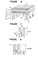
- Figures 1, 12 and 13 illustrate one embodiment of the magnetic head'according to the present invention, in which Figure 1 is a front view, Figure 12 is a plan view, and Figure 13 is a bottom view.
- the recording-and-reproducing core 141 and the erasing core 142 are alternately disposed, the respective cores having the non-magnetic members 109A and 109B. Both these cores are substantially in the shape of a letter "U", wherein the non-magnetic member 109A is held between the erasing cores 142, while the recording-and-reproducing core 141 is held between the non-magnetic members 109B.
- the recording-and-reproducing winding 131 is wound on and around one of the legs of the U-shaped recording-and-reproducing core 141 inclusive of the non-magnetic members 109B; while, the erasing winding 132 is wound on and around one of the legs of the U-shaped erasing cores 142 inclusive of the non-magnetic member 109A.
- At the bottom part of the recording-and-reproducing core 141 there is formed the recording-and-reproducing magnetic gap 121; while, at the bottom part of each erasing core 142, there is formed the erasing magnetic gap 122.
- the transverse plate 114 is joined at and on the open end part of the U-shaped recording-and-reproducing core 141, while the transverse plates 119 are joined at and on the open end part of the U-shaped erasing cores 142, each of the transverse plates forming a part of the magnetic paths. Joining of these transverse plates 114 and 119 are effected by use of an epoxy type or a cyanoacrylic type adhesive agent.
- the length LA(E) of the erasing core 142 is made shorter than the length LA(R/W) of the recording-and-reproducing core 141.
- the same can be said of the non-magnetic members 109A and 109B.
- both recording-and-reproducing core 141 and non-magnetic member 109A have the same length LA(R/W)
- both erasing cores 142 and non-magnetic members 109B have the same length LA(E).
- Figure 14 in the form of a flow chart.
- Figures 15 through 18 the sequence of manufacture of the magnetic head is illustrated in Figures 15 through 18.
- the magnetic gap 102 is formed of glass or like materials having a large magnetic resistance by means of vapor-deposition, sputtering, and so on (vide: Figure 15). That is to say, these magnetic members 171 and 172 are put together in an integral structure by fusion-bonding of the glass material 109 from the inside of the connection between both magnetic members (vide: step FAl in Figure 14).
- the first non-magnetic member 181 having its cross-sectional shape of a substantially non- angled "U” and the second/magnetic member 182 having the planar shape are put together to form an integral core structure (vide: step FA2 in Figure 14).
- This joining may also be done by use of an epoxy type adhesive agent, and so on.
- both assembled magnetic member and assembled non-magnetic member are put together through a joining layer 110 of an epoxy type adhesive agent, or the like in such a manner that the top surface of the assembled non-magnetic member 181 may be joined with the bottom surface of the assembled magnetic member 172 (vide: step FB in Figure 14).
- the combination of the magnetic and non-magnetic members is sliced along the slice-lines 112 (vide: step FC in Figure 14).
- Figure 16 illustrates the state of the combination after the slicing. This slicing operation is done by use of an inner blade or an outer blade type slicing table, etc. so as to obtain the cores, each having a thickness of, for example, approximately 0.15 mm in the case of the information track density of 135TPT.
- the polishing work is effected, as shown in Figure 9(B), for removal of the irregularities on its sliced surface and for rendering it to be in a predetermined thickness (vide: step FD in Figure 14).
- the sliced thickness of the core and its surface roughness are kept at 0.12 mm and 0.02 pm, respectively, for which the lapping or polishing work is effected to render the sliced surface to be in a mirror-surface condition.
- This polishing work is done by the method as shown in Figures 17 and 18.
- a carrier 117 is placed on a grind stone 116.
- This carrier 117 has a number of openings 120 perforated therein, into each of which the sliced core as shown in Figure 16 is received with a small clearance between the circumference of the core and the surrounding frame opening.
- the thickness of the carrier plate 117 is made thinner than the finished thickness of the core 113 as polished (i.e., the thickness (T) as shown in Figure 9(B)).
- the sliced core 113 is placed into each and every opening 120, and then the core 113 is subjected to the polishing work on its both surfaces by means of a double surface grinding machine provided with the grind stones 115 and 116. That is to say, both surfaces of the core 113 as sliced is subjected to the simultaneous polishing, in the course of which it is lapped or polished with the properly selected grind stones 115 and 116 (see: Figure 18).
- the core 113 is in the form of a closed frame having no open end part, unlike the conventional core as shown in Figures 7 to 10, it shows high strength against external force at the time of the polishing work with the consequence that occurrence of the cracks 118 as shown in Figure 10 becomes subdued. Also, since the polishing work is performed by use of the carrier plate 117, into each and every opening 120 of which the core 113 is placed, there is no necessity for additional fixing means such as adhesive agent, and so on. On account of this, a large quantity of cores 113 can be worked simultaneously.
- the recording-and-reproducing core 141 in the form of a letter "W", in its cross-section, the legs of which are upright and parallel one another.
- the erasing core 142 the same thing can be said of its shape with the exception that the erasing magnetic gap 122 is larger than the recording-and-reproducing magnetic gap 121.
- the erasing core can also be manufactured following the same steps as those described in the foregoing.
- step FF in Figure 14 assembly of the magnetic head 100 is carried out (vide: step FF in Figure 14).
- the recording-and-reproducing core 141 is held between the two erasing cores 142 by way of the non-magnetic member, the combination being sticked together by use of an epoxy type adhesive agent, etc. to form an integral three-layered structure.
- the recording-and-reproducing winding 131 and the erasing winding 132 are respectively mounted on the leg part of the recording-and-reproducing core 141 and the erasing core 142.
- the transverse plates 114 and l19 are joined to the respective recording-and-reproducing core 141 and erasing core 142 in a manner to span the end parts of the legs of each core by use of an epoxy type adhesive agent, etc.
- the non-magnetic member 182 is dispensed with, in contrast to the above-described embodiment, and the non-magnetic member 181 is joined to the second magnetic member 172 with its leg portions being directed thereto.
- combination of the non-magnetic members 181 and 182 is joined to the combination of the magnetic members 171 and 172 in opposite direction to that of the embodiment shown in Figure 16, i.e., the bottom surface of the non-magnetic member 182 is joined together with the bottom surface of the magnetic member 172.
- the non-magnetic member 281 is in the form of a rectangular frame from the beginning.
- the assembled core in its state prior to cutting along the center slicing line, is in the form of a frame having no open end, which prevents the undesirable cracks from being created.
- the present invention is not limited at all to the above-described embodiments, but its shape and size, in particular, may be appropriately varied.
- the applicable field of the present invention is also not limited to the floppy alone.
- the closure of the open end of the magnetic member or the non-magnetic member may be done by joining the open ends of these two members, this is not the only alternative, but any other expedients may be adopted such as fastening an appropriate member to the open end thererof.
- the polishing work of the assembled core is done in the state of the open ends of the constituent elements being closed, the occurrence of the cracks can be subdued, and the thinning of the core can be realized. Furthermore, the present invention provides various favourable effects such that both surfaces of the core can be polished at the same time, and that the polishing work can be simplified by use of the carrier plate, which contributes to improvement in the productivity of the core, and so forth.
Abstract
Description
- This invention relates to a magnetic head of a magnetic disc device for use as, for example, an external memory device. More particularly, the present invention is concerned with a magnetic head suitable for such memory device having its core made of a hard and brittle material as the principal component, and a method for manufacturing such magnetic head.
- As one of the external memory devices such as a small-sized computer, and so forth, there has been used widely a flexible disc device (which will hereinafter be called simply "floppy"). As the magnetic head to be used as the driver for this floppy, there has been known one which is disclosed in, for example, Unexamined Japanese Patent Publication No. 40118/1975. This magnetic head is of a three-layered structure, in which a recording-and-reproducing core and two erasing cores are in an alternate arrangement, the former being magnetically insulated from the latter.
- In the following, a conventional magnetic head and a method for its manufacture will be described in reference to the accompanying drawing. Figures 2 to 4 illustrate one example of the conventional magnetic head, wherein Figure 2 is a front view of the magnetic head; Figure 3 is a plan view of it; and Figure 4 is a bottom view thereof. In these Figures 2 to 4, the magnetic head 1 is made up of two
erasing cores 42 and a single recording-and-reproducingcore 41 as the principal structural elements, each of thecores magnetic gap 21 and an erasingmagnetic gap 22. Atransverse plate 14 and atransverse plate 19 to constitute magnetic paths are respectively joined with thecores magnetic gaps winding 31 based on the theory of electro-magnetic conversion, there can be obtained a magnetic flux necessary for the recording-and-reproducingmagnetic gap 21; inversely, when the magnetic head 1 travels on and through information tracks recorded on the magnetic medium, there can be obtained a corresponding electric voltage in the recording-and-reproducing winding 31 due to the change in the magnetic flux to be produced in the recording-and-reproducingmagnetic gap 21. By the way, the two erasingcores 42 possesses required recording density as well as interchangeability among various floppy memory devices; in other words, it can be effectively used for recording by one memory device and reproducing by another recording device, as is taught in U.S. Patent specification No. 2,987,582. - In the following, the method for manufacturing the above-described magnetic head will be explained in reference to Figure 5 which illustrates a flow chart of the principal steps for its manufacture, and Figures 6 to 11 which illustrate schematically what is actually done at each of the manufacturing steps.
- To begin with, the first magnetic material 7:, the second
magnetic material 72 and thenon-magnetic material 81 are put together by use ofglass 9, or an epoxy type adhesive agent, or a cyanoacrylic type adhesive agent to form an integral core structure as shown in Figure 6 (vide: steps Fl and F2 in Figure 5). Subsequently, the integral core structure is halved along the center cutting line 11, and then each of the halved structures is sliced along the slice-cutting line 12 on an outer or inner blade-type slicing table (vide: step F3 in Figure 5), whereby the erasingcore 42 as shown in Figure 7 and the recording-and-reproducingcore 41 as shown in Figure 8 can be substantially obtained. It should be noted that, at the time of the cutting, consideration is taken to the sizes (length) L(E) and L(R/W) for therespective cores - When these
cores core adhesive stool 14 by use of an adhesive agent such as wax, etc. so as to be readily peelable, followed by polishing the same on agrind stone 15 in the dry or wet system. The state of the core after its polishing work is as shown in Figure 9(B), wherein its thickness is reduced from (T + A) to (T). Incidentally, a reference letter (AL) in Figures 9(A) and 9(B) designates a width of a joininglayer 10 between themagnetic material 72 and thenon-magnetic material 81, while a reference letter (GL) denotes a width of themagnetic gap 2. - After completion of the above-described work, these
cores - By the way, owing the advancement in technology in recent years, quantity of information to be stored in a single sheet of floppy tends to increase more and more. In particular, there has been widely adopted a method of narrowing breadth of the track for increasing the number of tracks to be contained in the radial direction of the floppy of one and the same shape and size. When the track density increases and the track width becomes narrow as such, the width of the erasing core and the recording-and-reproducing core should be made correspondingly thin.
- Describing more specifically, as the method for increasing the capacity of the floppy, it may be contemplated to shorten a magnetic flux reversing interval, to increase the number of information tracks, to increase the number of floppy sheets to be used, or others. For the purpose of increasing the number of the information tracks, thinning of the
cores core 41 would be approximately 0.33 mm and that of the erasingcore 42 would be approximately 0.165 mm or so. In order therefore to increase density of the information tracks from 48TPI to 96TPI, 135TPI, or 200TPI, the thickness of the core must be reduced more and more with the consequence that the technique of such thinning work of the core has added much more importance to the manufacture of the magnetic head. On account of this, more efficient and productive technique of thinning the core has been desired. - From this standpoint of thinning the core, however, the above-described conventional technique cannot always be said to be favourable. The reason for this is that, firstly, since the
cores cracks 18 in their polishing work, as shown in Figure 10; secondly, since thecores magnetic materials glass 9, owing to which this U-shaped portion is weaker than thenon-magnetic material 81 forming the L-shaped portion against external force. Thecracks 18 to be possibly created in this U-shaped portion exercises remarkable influence on the magnetic properties of the core, and is liable to lower the rate of yield of the core. - Further, cracks may possibly take place even at the other steps than the polishing work. For instance, in the washing step, an ultra-sonic washer or the like is employed for the necessity of efficiently washing a large quantity of cores which have been peeled off the
adhesive stool 14, when the cores get entangled among themselves to bread a part of the U-shaped or L-shaped portions thereof. - The present invention has been made in view of the above-described disadvantages inherent in the conventional magnetic head and the method of its manufacture, and aims at providing an improved magnetic head and the method of its manufacture, according to which the thinning of the core is suitably attained together with the improved productivity.
- Preferred ways of carrying out the invention are described in detail below with reference to drawings which illustrate specific embodiments thereof, in which:-
- Figure 1 is a front view showing one embodiment of the magnetic head according to the present invention;
- Figures 2 to 4 are respectively front view, plan view and bottom view showing one example of a conventional magnetic head;
- Figure 5 is a flow chart showing one example of conventional method for producing the magnetic head;
- Figures 6 to 9 are respectively a perspective view of the cores as assembled, a front view of the erasing core, a front view of the recording-and-reproducing core, and enlarged views of the assembled core showing its surface conditions, one as sliced and the other as polished, for explaining the steps of manufacturing the conventional magnetic head;
- Figures 10 and 11 are explanatory diagrams for the polishing step in the conventional method for manufacture;
- Figure 12 is a plan view of the magnetic head according to the present invention as shown in Figure 1 above;
- Figure 13 is a bottom view of the same;
- Figure 14 is a flow chart showing one example of the method for manufacturing the magnetic head according to the present invention;
- Figures 15 and 16 are respectively perspective views showing the magnetic head as assembled, but before it is halved;
- Figures 17 and 18 are explanatory diagrams for the polishing step according to the present invention; and
- Figures 19 to 24 illustrate different structures of the assembled core according to the present invention.
- The characteristic point of the present invention resides in that the polishing work is effected while closing the open end of the magnetic member and the non-magnetic member, after which appropriate cutting is done to form an assembled body of the magnetic core and the non-magnetic structure.
- Since the polishing work is performed in the state of the open end of the magnetic and non-magnetic members as assembled being closed, the core exhibit sufficient durability against external force, hence no cracks are produced.
- In the following, the magnetic head as well as the method for its manufacture according to the present invention will be described in detail in reference to the accompanying drawing.
- Figures 1, 12 and 13 illustrate one embodiment of the magnetic head'according to the present invention, in which Figure 1 is a front view, Figure 12 is a plan view, and Figure 13 is a bottom view. In these Figures 1, 12 and 13, the recording-and-reproducing
core 141 and theerasing core 142 are alternately disposed, the respective cores having thenon-magnetic members non-magnetic member 109A is held between theerasing cores 142, while the recording-and-reproducingcore 141 is held between thenon-magnetic members 109B. - The recording-and-reproducing
winding 131 is wound on and around one of the legs of the U-shaped recording-and-reproducingcore 141 inclusive of thenon-magnetic members 109B; while, the erasing winding 132 is wound on and around one of the legs of the U-shaped erasingcores 142 inclusive of thenon-magnetic member 109A. At the bottom part of the recording-and-reproducingcore 141, there is formed the recording-and-reproducingmagnetic gap 121; while, at the bottom part of each erasingcore 142, there is formed the erasingmagnetic gap 122. Thetransverse plate 114 is joined at and on the open end part of the U-shaped recording-and-reproducingcore 141, while thetransverse plates 119 are joined at and on the open end part of the U-shapederasing cores 142, each of the transverse plates forming a part of the magnetic paths. Joining of thesetransverse plates core 142 is made shorter than the length LA(R/W) of the recording-and-reproducingcore 141. The same can be said of thenon-magnetic members core 141 andnon-magnetic member 109A have the same length LA(R/W), while both erasingcores 142 andnon-magnetic members 109B have the same length LA(E). - In the following, explanations will be given as to the method of manufacturing the magnetic head of the above-described construction. One example of such production method is shown in Figure 14 in the form of a flow chart. Also, the sequence of manufacture of the magnetic head is illustrated in Figures 15 through 18. As seen from these Figures 14 through 18, at the joined end part between the first
magnetic member 171 having its cross-sectional shape of an angled "U" and the secondmagnetic member 172 having the planar shape, themagnetic gap 102 is formed of glass or like materials having a large magnetic resistance by means of vapor-deposition, sputtering, and so on (vide: Figure 15). That is to say, thesemagnetic members glass material 109 from the inside of the connection between both magnetic members (vide: step FAl in Figure 14). - In the same manner, the first
non-magnetic member 181 having its cross-sectional shape of a substantially non- angled "U" and the second/magnetic member 182 having the planar shape are put together to form an integral core structure (vide: step FA2 in Figure 14). This joining may also be done by use of an epoxy type adhesive agent, and so on. After joining of these non-magnetic members, both assembled magnetic member and assembled non-magnetic member are put together through a joininglayer 110 of an epoxy type adhesive agent, or the like in such a manner that the top surface of the assemblednon-magnetic member 181 may be joined with the bottom surface of the assembled magnetic member 172 (vide: step FB in Figure 14). - After lapse of time for sufficient curing of the adhesive agent, the combination of the magnetic and non-magnetic members is sliced along the slice-lines 112 (vide: step FC in Figure 14). Figure 16 illustrates the state of the combination after the slicing. This slicing operation is done by use of an inner blade or an outer blade type slicing table, etc. so as to obtain the cores, each having a thickness of, for example, approximately 0.15 mm in the case of the information track density of 135TPT.
- Since the sliced surface of the core, after the above-described slicing work, is rough and irregular as has already been shown in Figure 9(A), the polishing work is effected, as shown in Figure 9(B), for removal of the irregularities on its sliced surface and for rendering it to be in a predetermined thickness (vide: step FD in Figure 14). In the case of the information track density being 135TPI, the sliced thickness of the core and its surface roughness are kept at 0.12 mm and 0.02 pm, respectively, for which the lapping or polishing work is effected to render the sliced surface to be in a mirror-surface condition. This polishing work is done by the method as shown in Figures 17 and 18.
- Explaining in detail, a
carrier 117 is placed on agrind stone 116. Thiscarrier 117 has a number ofopenings 120 perforated therein, into each of which the sliced core as shown in Figure 16 is received with a small clearance between the circumference of the core and the surrounding frame opening. The thickness of thecarrier plate 117 is made thinner than the finished thickness of the core 113 as polished (i.e., the thickness (T) as shown in Figure 9(B)). The slicedcore 113 is placed into each and everyopening 120, and then thecore 113 is subjected to the polishing work on its both surfaces by means of a double surface grinding machine provided with thegrind stones grind stones 115 and 116 (see: Figure 18). - It will be seen that, in this polishing work, since the
core 113 is in the form of a closed frame having no open end part, unlike the conventional core as shown in Figures 7 to 10, it shows high strength against external force at the time of the polishing work with the consequence that occurrence of the cracks 118 as shown in Figure 10 becomes subdued. Also, since the polishing work is performed by use of thecarrier plate 117, into each and everyopening 120 of which thecore 113 is placed, there is no necessity for additional fixing means such as adhesive agent, and so on. On account of this, a large quantity ofcores 113 can be worked simultaneously. - After the above-described polishing work, there follows cutting of the
core 113 along the center cutting line 111 as shown in Figure 16 (vide: step FE in Figure 14), by which the recording-and-reproducingcore 141 in the form of a letter "W", in its cross-section, the legs of which are upright and parallel one another. For the erasingcore 142, the same thing can be said of its shape with the exception that the erasingmagnetic gap 122 is larger than the recording-and-reproducingmagnetic gap 121. The erasing core can also be manufactured following the same steps as those described in the foregoing. - Subsequently, assembly of the
magnetic head 100 is carried out (vide: step FF in Figure 14). As shown in Figures 1, 12 and 13, the recording-and-reproducingcore 141 is held between the two erasingcores 142 by way of the non-magnetic member, the combination being sticked together by use of an epoxy type adhesive agent, etc. to form an integral three-layered structure. Thereafter, the recording-and-reproducing winding 131 and the erasing winding 132 are respectively mounted on the leg part of the recording-and-reproducingcore 141 and the erasingcore 142. Subsequently, thetransverse plates 114 and l19 are joined to the respective recording-and-reproducingcore 141 and erasingcore 142 in a manner to span the end parts of the legs of each core by use of an epoxy type adhesive agent, etc. - In the following, the other embodiments of the present invention will be described in reference to Figures 19 to 24.
- In the embodiment as shown in Figures 19 and 20, the
non-magnetic member 182 is dispensed with, in contrast to the above-described embodiment, and thenon-magnetic member 181 is joined to the secondmagnetic member 172 with its leg portions being directed thereto. - r
- In the embodiment as shown in Figures 21 and 22, combination of the
non-magnetic members magnetic members non-magnetic member 182 is joined together with the bottom surface of themagnetic member 172. - In the embodiment shown in Figures 23 and 24, the
non-magnetic member 281 is in the form of a rectangular frame from the beginning. - In the core of either structure as described above, the assembled core, in its state prior to cutting along the center slicing line, is in the form of a frame having no open end, which prevents the undesirable cracks from being created.
- Moreover, the present invention is not limited at all to the above-described embodiments, but its shape and size, in particular, may be appropriately varied. The applicable field of the present invention is also not limited to the floppy alone. For others, while the closure of the open end of the magnetic member or the non-magnetic member may be done by joining the open ends of these two members, this is not the only alternative, but any other expedients may be adopted such as fastening an appropriate member to the open end thererof.
- As has been described in the foregoing, according to the magnetic head and the method for its manufacture of the present invention, since the polishing work of the assembled core is done in the state of the open ends of the constituent elements being closed, the occurrence of the cracks can be subdued, and the thinning of the core can be realized. Furthermore, the present invention provides various favourable effects such that both surfaces of the core can be polished at the same time, and that the polishing work can be simplified by use of the carrier plate, which contributes to improvement in the productivity of the core, and so forth.
Claims (5)
Applications Claiming Priority (2)
| Application Number | Priority Date | Filing Date | Title |
|---|---|---|---|
| JP36274/85 | 1985-02-27 | ||
| JP60036274A JPS61196412A (en) | 1985-02-27 | 1985-02-27 | Magnetic head and its manufacture |
Publications (2)
| Publication Number | Publication Date |
|---|---|
| EP0193044A1 true EP0193044A1 (en) | 1986-09-03 |
| EP0193044B1 EP0193044B1 (en) | 1990-05-09 |
Family
ID=12465192
Family Applications (1)
| Application Number | Title | Priority Date | Filing Date |
|---|---|---|---|
| EP86101864A Expired - Lifetime EP0193044B1 (en) | 1985-02-27 | 1986-02-14 | Magnetic head and method for manufacturing the same |
Country Status (4)
| Country | Link |
|---|---|
| US (1) | US4745676A (en) |
| EP (1) | EP0193044B1 (en) |
| JP (1) | JPS61196412A (en) |
| DE (1) | DE3671121D1 (en) |
Cited By (1)
| Publication number | Priority date | Publication date | Assignee | Title |
|---|---|---|---|---|
| EP0456316A2 (en) * | 1990-05-08 | 1991-11-13 | Koninklijke Philips Electronics N.V. | Compatible magnetic head assembly |
Citations (5)
| Publication number | Priority date | Publication date | Assignee | Title |
|---|---|---|---|---|
| US4058846A (en) * | 1976-06-21 | 1977-11-15 | International Business Machines Corporation | Grounded transducer for magnetic record disks |
| EP0031402A1 (en) * | 1979-12-06 | 1981-07-08 | International Business Machines Corporation | Read/write and tunnel erase magnetic head assemblies |
| EP0110050A1 (en) * | 1982-10-01 | 1984-06-13 | Mitsubishi Denki Kabushiki Kaisha | Disc drive for flexible discs with different track widths |
| DE3427252A1 (en) * | 1983-07-29 | 1985-02-21 | Canon Denshi K.K., Chichibu, Saitama | Magnetic head |
| DE3427253A1 (en) * | 1983-07-26 | 1985-02-21 | Canon Denshi K.K., Chichibu, Saitama | Magnetic head |
Family Cites Families (3)
| Publication number | Priority date | Publication date | Assignee | Title |
|---|---|---|---|---|
| US3846840A (en) * | 1973-08-10 | 1974-11-05 | Ibm | Read/write and longitudinal edge erase head assembly having multiple similarly shaped layers |
| JPS5860423A (en) * | 1981-10-07 | 1983-04-09 | Hitachi Metals Ltd | Magnetic head device |
| JPS58150126A (en) * | 1982-03-02 | 1983-09-06 | Hitachi Ltd | Production of magnetic head |
-
1985
- 1985-02-27 JP JP60036274A patent/JPS61196412A/en active Pending
-
1986
- 1986-02-07 US US06/827,266 patent/US4745676A/en not_active Expired - Fee Related
- 1986-02-14 EP EP86101864A patent/EP0193044B1/en not_active Expired - Lifetime
- 1986-02-14 DE DE8686101864T patent/DE3671121D1/en not_active Expired - Fee Related
Patent Citations (5)
| Publication number | Priority date | Publication date | Assignee | Title |
|---|---|---|---|---|
| US4058846A (en) * | 1976-06-21 | 1977-11-15 | International Business Machines Corporation | Grounded transducer for magnetic record disks |
| EP0031402A1 (en) * | 1979-12-06 | 1981-07-08 | International Business Machines Corporation | Read/write and tunnel erase magnetic head assemblies |
| EP0110050A1 (en) * | 1982-10-01 | 1984-06-13 | Mitsubishi Denki Kabushiki Kaisha | Disc drive for flexible discs with different track widths |
| DE3427253A1 (en) * | 1983-07-26 | 1985-02-21 | Canon Denshi K.K., Chichibu, Saitama | Magnetic head |
| DE3427252A1 (en) * | 1983-07-29 | 1985-02-21 | Canon Denshi K.K., Chichibu, Saitama | Magnetic head |
Cited By (2)
| Publication number | Priority date | Publication date | Assignee | Title |
|---|---|---|---|---|
| EP0456316A2 (en) * | 1990-05-08 | 1991-11-13 | Koninklijke Philips Electronics N.V. | Compatible magnetic head assembly |
| EP0456316A3 (en) * | 1990-05-08 | 1992-09-02 | Laser Magnetic Storage International Company | Compatible magnetic head assembly |
Also Published As
| Publication number | Publication date |
|---|---|
| DE3671121D1 (en) | 1990-06-13 |
| EP0193044B1 (en) | 1990-05-09 |
| US4745676A (en) | 1988-05-24 |
| JPS61196412A (en) | 1986-08-30 |
Similar Documents
| Publication | Publication Date | Title |
|---|---|---|
| WO1994002938A1 (en) | Composite metal and ferrite head transducer and manufacturing method therefor | |
| EP0193044B1 (en) | Magnetic head and method for manufacturing the same | |
| US5402294A (en) | Laminated, high frequency, magnetic transducer and manufacturing method therefor | |
| US5029380A (en) | Method of making a composite core transducer | |
| US5333372A (en) | Method of manufacturing a magnetic head | |
| US5001588A (en) | Composite core magnetic transducer having a wedge shaped core portion | |
| KR910000207B1 (en) | Composite type magnetic head | |
| JP3519523B2 (en) | Magnetic head and method of manufacturing the same | |
| JPS62117117A (en) | Manufacture of magnetic head | |
| JPH042408Y2 (en) | ||
| JP2594168B2 (en) | Floating magnetic head | |
| JPH09212818A (en) | Magnetic head for magnetic disk and its production | |
| JP3381300B2 (en) | Manufacturing method of magnetic head | |
| KR19980045563A (en) | Magnetic head and its manufacturing method | |
| JPS6126912A (en) | Thin film magnetic head | |
| JPH05282619A (en) | Magnetic head | |
| JPH08138206A (en) | Production of magnetic head | |
| JPS60185214A (en) | Magnetic head | |
| JPS6251012A (en) | Magnetic head and its production | |
| JPH01133207A (en) | Magnetic head | |
| JPH0721508A (en) | Magnetic head for hard disk and its production | |
| JPH03116406A (en) | Production of chip for magnetic head | |
| JPS61214109A (en) | Magnetic head and its manufacture | |
| JPS59132413A (en) | Manufacture for magnetic head core | |
| JPH10255223A (en) | Manufacture of magnetic head |
Legal Events
| Date | Code | Title | Description |
|---|---|---|---|
| PUAI | Public reference made under article 153(3) epc to a published international application that has entered the european phase |
Free format text: ORIGINAL CODE: 0009012 |
|
| AK | Designated contracting states |
Kind code of ref document: A1 Designated state(s): DE FR GB |
|
| 17P | Request for examination filed |
Effective date: 19861103 |
|
| 17Q | First examination report despatched |
Effective date: 19881031 |
|
| GRAA | (expected) grant |
Free format text: ORIGINAL CODE: 0009210 |
|
| AK | Designated contracting states |
Kind code of ref document: B1 Designated state(s): DE FR GB |
|
| REF | Corresponds to: |
Ref document number: 3671121 Country of ref document: DE Date of ref document: 19900613 |
|
| ET | Fr: translation filed | ||
| PLBE | No opposition filed within time limit |
Free format text: ORIGINAL CODE: 0009261 |
|
| STAA | Information on the status of an ep patent application or granted ep patent |
Free format text: STATUS: NO OPPOSITION FILED WITHIN TIME LIMIT |
|
| 26N | No opposition filed | ||
| PGFP | Annual fee paid to national office [announced via postgrant information from national office to epo] |
Ref country code: FR Payment date: 19920211 Year of fee payment: 7 |
|
| PG25 | Lapsed in a contracting state [announced via postgrant information from national office to epo] |
Ref country code: FR Effective date: 19931029 |
|
| REG | Reference to a national code |
Ref country code: FR Ref legal event code: ST |
|
| REG | Reference to a national code |
Ref country code: GB Ref legal event code: 746 Effective date: 19951026 |
|
| PGFP | Annual fee paid to national office [announced via postgrant information from national office to epo] |
Ref country code: GB Payment date: 19960205 Year of fee payment: 11 |
|
| PGFP | Annual fee paid to national office [announced via postgrant information from national office to epo] |
Ref country code: DE Payment date: 19960215 Year of fee payment: 11 |
|
| PG25 | Lapsed in a contracting state [announced via postgrant information from national office to epo] |
Ref country code: GB Effective date: 19970214 |
|
| GBPC | Gb: european patent ceased through non-payment of renewal fee |
Effective date: 19970214 |
|
| PG25 | Lapsed in a contracting state [announced via postgrant information from national office to epo] |
Ref country code: DE Effective date: 19971101 |