EP0336273A2 - Pulse Doppler radar - Google Patents
Pulse Doppler radar Download PDFInfo
- Publication number
- EP0336273A2 EP0336273A2 EP89105518A EP89105518A EP0336273A2 EP 0336273 A2 EP0336273 A2 EP 0336273A2 EP 89105518 A EP89105518 A EP 89105518A EP 89105518 A EP89105518 A EP 89105518A EP 0336273 A2 EP0336273 A2 EP 0336273A2
- Authority
- EP
- European Patent Office
- Prior art keywords
- radar
- pulse
- period
- doppler
- range
- Prior art date
- Legal status (The legal status is an assumption and is not a legal conclusion. Google has not performed a legal analysis and makes no representation as to the accuracy of the status listed.)
- Granted
Links
Images


Classifications
-
- G—PHYSICS
- G01—MEASURING; TESTING
- G01S—RADIO DIRECTION-FINDING; RADIO NAVIGATION; DETERMINING DISTANCE OR VELOCITY BY USE OF RADIO WAVES; LOCATING OR PRESENCE-DETECTING BY USE OF THE REFLECTION OR RERADIATION OF RADIO WAVES; ANALOGOUS ARRANGEMENTS USING OTHER WAVES
- G01S13/00—Systems using the reflection or reradiation of radio waves, e.g. radar systems; Analogous systems using reflection or reradiation of waves whose nature or wavelength is irrelevant or unspecified
- G01S13/02—Systems using reflection of radio waves, e.g. primary radar systems; Analogous systems
- G01S13/06—Systems determining position data of a target
- G01S13/08—Systems for measuring distance only
- G01S13/10—Systems for measuring distance only using transmission of interrupted, pulse modulated waves
- G01S13/26—Systems for measuring distance only using transmission of interrupted, pulse modulated waves wherein the transmitted pulses use a frequency- or phase-modulated carrier wave
- G01S13/28—Systems for measuring distance only using transmission of interrupted, pulse modulated waves wherein the transmitted pulses use a frequency- or phase-modulated carrier wave with time compression of received pulses
- G01S13/284—Systems for measuring distance only using transmission of interrupted, pulse modulated waves wherein the transmitted pulses use a frequency- or phase-modulated carrier wave with time compression of received pulses using coded pulses
- G01S13/288—Systems for measuring distance only using transmission of interrupted, pulse modulated waves wherein the transmitted pulses use a frequency- or phase-modulated carrier wave with time compression of received pulses using coded pulses phase modulated
-
- G—PHYSICS
- G01—MEASURING; TESTING
- G01S—RADIO DIRECTION-FINDING; RADIO NAVIGATION; DETERMINING DISTANCE OR VELOCITY BY USE OF RADIO WAVES; LOCATING OR PRESENCE-DETECTING BY USE OF THE REFLECTION OR RERADIATION OF RADIO WAVES; ANALOGOUS ARRANGEMENTS USING OTHER WAVES
- G01S13/00—Systems using the reflection or reradiation of radio waves, e.g. radar systems; Analogous systems using reflection or reradiation of waves whose nature or wavelength is irrelevant or unspecified
- G01S13/02—Systems using reflection of radio waves, e.g. primary radar systems; Analogous systems
- G01S13/06—Systems determining position data of a target
- G01S13/08—Systems for measuring distance only
- G01S13/10—Systems for measuring distance only using transmission of interrupted, pulse modulated waves
- G01S13/22—Systems for measuring distance only using transmission of interrupted, pulse modulated waves using irregular pulse repetition frequency
-
- G—PHYSICS
- G01—MEASURING; TESTING
- G01S—RADIO DIRECTION-FINDING; RADIO NAVIGATION; DETERMINING DISTANCE OR VELOCITY BY USE OF RADIO WAVES; LOCATING OR PRESENCE-DETECTING BY USE OF THE REFLECTION OR RERADIATION OF RADIO WAVES; ANALOGOUS ARRANGEMENTS USING OTHER WAVES
- G01S13/00—Systems using the reflection or reradiation of radio waves, e.g. radar systems; Analogous systems using reflection or reradiation of waves whose nature or wavelength is irrelevant or unspecified
- G01S13/02—Systems using reflection of radio waves, e.g. primary radar systems; Analogous systems
- G01S13/06—Systems determining position data of a target
- G01S13/08—Systems for measuring distance only
- G01S13/10—Systems for measuring distance only using transmission of interrupted, pulse modulated waves
- G01S13/30—Systems for measuring distance only using transmission of interrupted, pulse modulated waves using more than one pulse per radar period
-
- G—PHYSICS
- G01—MEASURING; TESTING
- G01S—RADIO DIRECTION-FINDING; RADIO NAVIGATION; DETERMINING DISTANCE OR VELOCITY BY USE OF RADIO WAVES; LOCATING OR PRESENCE-DETECTING BY USE OF THE REFLECTION OR RERADIATION OF RADIO WAVES; ANALOGOUS ARRANGEMENTS USING OTHER WAVES
- G01S13/00—Systems using the reflection or reradiation of radio waves, e.g. radar systems; Analogous systems using reflection or reradiation of waves whose nature or wavelength is irrelevant or unspecified
- G01S13/02—Systems using reflection of radio waves, e.g. primary radar systems; Analogous systems
- G01S13/50—Systems of measurement based on relative movement of target
- G01S13/52—Discriminating between fixed and moving objects or between objects moving at different speeds
- G01S13/522—Discriminating between fixed and moving objects or between objects moving at different speeds using transmissions of interrupted pulse modulated waves
- G01S13/524—Discriminating between fixed and moving objects or between objects moving at different speeds using transmissions of interrupted pulse modulated waves based upon the phase or frequency shift resulting from movement of objects, with reference to the transmitted signals, e.g. coherent MTi
- G01S13/53—Discriminating between fixed and moving objects or between objects moving at different speeds using transmissions of interrupted pulse modulated waves based upon the phase or frequency shift resulting from movement of objects, with reference to the transmitted signals, e.g. coherent MTi performing filtering on a single spectral line and associated with one or more range gates with a phase detector or a frequency mixer to extract the Doppler information, e.g. pulse Doppler radar
- G01S13/532—Discriminating between fixed and moving objects or between objects moving at different speeds using transmissions of interrupted pulse modulated waves based upon the phase or frequency shift resulting from movement of objects, with reference to the transmitted signals, e.g. coherent MTi performing filtering on a single spectral line and associated with one or more range gates with a phase detector or a frequency mixer to extract the Doppler information, e.g. pulse Doppler radar using a bank of range gates or a memory matrix
Definitions
- the invention relates to a pulse Doppler radar of the type specified in the preamble of claim 1.
- a possible Doppler frequency shift f D of the echo signals can be measured by coherent integration of the echo signals received within a so-called CPI (coherent processing interval), and a statement about the radial speed of a target can be derived therefrom.
- CPI coherent processing interval
- the requirement for simultaneously large uniqueness ranges for the distance and the Doppler frequency of a target therefore generally leads to a contradiction in the definition of the pulse repetition frequency PRF.
- compromises in the definition of the pulse repetition frequency must therefore be made depending on the particular application.
- a distinction is usually made for the operating mode between low (LPRF), medium (MPRF) and high (HPRF) pulse repetition frequency.
- LPRF low
- MPRF medium
- HPRF high
- ground radar systems for example for flight monitoring
- transmission signals with periodically repeated simple rectangular or coded pulses are used.
- the characteristic feature for ground radars is a relatively low and generally constant PRF (approx. 1 kHz), so that the practically occurring target distances can be clearly measured with the radar.
- PRF approximately 1 kHz
- the echo signals of the useful targets only compete with the ground clutter found in the respective radar cell.
- a time-dependent control (STC) in the radar receiver can dampen the proximity clutter that occurs with high amplitudes without simultaneously reducing the amplitudes in the echo signals and thus reducing the detectability of distant targets. In clutter-free areas of the observation area the target discovery is therefore only limited by the receiver noise.
- On-board radar systems are often designed as so-called multimode pulse Doppler radars /1.2/.
- the transmission signals are made up of periodically repeated simple square-wave or coded pulses, but the pulse repetition frequencies used are not limited to the LPRF range (approx. 1 kHz) but MPRF (10 - 20 kHz) and HPRF (approx. 200 kHz), are also used and mutually depending on the respective task (target search, tracking).
- the target range is not or not clearly measured in the HPRF or MPRF radar. Because of the distance ambiguities that arise, i.a. no STC control used in these modes. In these situations, however, the reflections on the earth's surface that reach the receiver via the side lobes of the antenna (side lobe clutter) are no longer negligible, but rather have a relatively high echo amplitude. On the one hand, this fact leads to high demands on the antenna sub-peaks for on-board radars. On the other hand, the problem of clutter and useful signal separation using methods of digital signal processing by the short-range and side lobe clutter for MPRF and HPRF radars is becoming increasingly important.
- the object of the present invention is therefore to provide a pulse Doppler radar suitable as an aircraft on-board radar with unambiguous target speed measurement, with which one improved target discovery and target parameter estimation is possible.
- an HPRF radar with a largely unambiguous Doppler frequency determination is used as the known system in the following and the same Doppler frequency uniqueness range is assumed for the system parameters of an embodiment of the invention.
- the variable that is decisive for the Doppler uniqueness range is the period T, so that the repetition frequency of the individual pulses is higher by a factor N than in the conventional HPRF radar.
- the pulse doubler radar according to the invention is therefore briefly referred to below as VHPRF (very high pulse repetition frequency) radar.
- Both the conventional HPRF radar and the VHPRF radar allow a very precise and unambiguous measurement of the radial speed of discovered usage targets.
- range gates does not yet easily give a value for the target range, since the range gate information is ambiguous. There is therefore no reason to increase the pulse repetition frequency even further compared to the usual HPRF radar.
- One of the main advantages of the VHPRF radar is that the signal / clutter ratio is within the one individual distance gates are significantly improved and the probability of target detection in the subsequent distance gate-wise Doppler processing is significantly increased, so that targets under unfavorable target aspect angles. that are covered by clutter on the HPRF radar can still be discovered.
- the very high range resolution by the individual range gates can also be used as detailed target information for target classification.
- the coding increases the immunity to interference from certain methods of deliberate interference, for which the coding can also be changed from interval to interval.
- the duty cycle can be selected with the VHPRF radar as with the HPRF radar and set to 40%, for example. This also means that the same power is emitted on average.
- eclipsing ie the partial or complete masking of an echo pulse by a transmission pulse, occurs with the HPRF and VHPRF radar, but in this case the very short pulse length of the VHPRF radar has the advantageous effect that a through Eclipsing concealed echo pulse train of a target echo due to the relative movement of the radar system and target after a shorter time is again so far shifted into the reception period that sufficient reception power is available for target detection.
- the pulse repetition rate of the HPRF radar is based on the requirement for a clear determination of the Doppler frequency and thus the radial speed of a target by the maximum expected relative target speed that occurs in the situation of a directly opposing target (head-on aspect).
- the pulse repetition frequency of an HPRF radar is therefore in the range above 100 kHz, typically around 200 kHz.
- the period T should be chosen correspondingly less than 10 ⁇ s, typically about 5 ⁇ s, for the VHPRF radar.
- the pulse repetition frequency in the VHPRF radar is then higher by a factor of N than the HPRF radar (with N as the code length of the code word repeated from radar period to radar period).
- the recovery time of the transmitter limits the pulse repetition frequency and thus the code length.
- a transmitting antenna with a multiplicity is therefore preferably active.
- Semiconductor components containing radiator elements are provided, which have only very short recovery times.
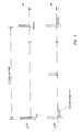
- a powerful short transmission pulse of typically 1 ⁇ s pulse duration is emitted as the transmission signal s (t) at the beginning of a radar period (FIG. 1 (a)).
- sampling values are obtained from the reception signal e (t) in sampling intervals which are associated with distance gates.
- a typical pulse repetition frequency of 1 kHz and thus a period of 1 ms there is a clear distance range of 150 km.
- a division of the reception time into 103 sampling intervals results in a distance resolution of 150 m.
- a target echo pulse appears in the received signal e (t) only in one or a few distance gates and the target distance can be measured uniquely (FIG. 1 (b)).
- Information about the speed of a target can be obtained ambiguously by evaluating several successive radar periods (burst), and finally by changing the PRF and comparing bursts with different PRF.
- the target speed is an important distinguishing feature between targets and clutter.
- only a comparatively low transmission power is available, so that the transmission signal form of the LPRF radar cannot be adopted. Examples of the modes of operation with medium (MPRF, FIG. 2) and high (HPRF. FIG. 3) which are common for on-board radar are therefore also described below.
- the resulting duty cycle TV ⁇ / PA is 40% in this exemplary HPRF transmission signal.
- the associated echo signal e (t) (Fig. 3, (b)) is processed in the radar receiver with a pulse-matched filter and sampled once or twice (according to the signal bandwidth) in each radar period.
- the samples obtained in a plurality of successive radar periods are subjected to Doppler processing for target detection and for estimating the target speed. In this case, there is no information about the target distance. Multi-target situations can then only be resolved via the radial speed.
- the echo signals are only with a low probability completely in the receive sections between two transmit pulses (FIG. 3, (b), receive signal e (t) A ).
- the target echo signals are predominantly partially covered by the transmission signals, which is referred to as eclipsing.
- a situation with a partially hidden echo signal e (t) B in FIG. 3 (d) outlines that the hidden part of the echo signal is indicated as a broken line.
- those in the case of FIG. 3 (d) obtained samples p (t) B (FIG. 3 (e)) from the weaker than the unobstructed echo signal e (t) A sample obtained p (t) A in FIG. 3, (c). Since the noise component in the received signal can be assumed to be the same in both cases, it is obvious that the target discovery becomes more difficult with increasing eclipsing.
- Ground clutter echoes that reach the radar receiver via the antenna main or side lobes are noticeable in the HPRF on-board radar in the Doppler frequency range up to the speed of the radar above ground.
- the only distinguishing feature between ground clutter and useful targets is then the Doppler frequency, so that distant (weak) useful targets can generally only be discovered in the clutter-free area on the Doppler frequency axis and these are flight targets that move towards the radar (head on aspect).
- Such useful target and clutter echoes can be completely separated from one another, thereby reducing the detection problem to a relatively simple target detection in noise.
- on-board radar systems In the target search phase, on-board radar systems generally the focus on a clear Doppler frequency estimate, because the respective target speed is an important recognition and differentiator between flight and e.g. Interfering objects (clutter). With the transmission signal described above and an X-band radar, radial speeds of today's aircraft can be clearly measured. Because of the high duty cycle (TV) and the resulting gain in integration in digital signal processing (Doppler filter bank, FFT), there is a large target detection range for the targets flying towards the radar. However, no information about the respective target distance is measured with the HPRF radar.
- TV high duty cycle
- FFT digital signal processing
- Echo signals of the targets moving away from the radar additively overlap with the (relatively strong) ground clutter echoes simultaneously received from the close range via the antenna sidelobes, i.e. in other words they are not in the clutter-free range on the Doppler frequency axis and become with the here sketched HPRF radar and at distant (weak) targets due to the ia low signal-to-clutter (S C) ratio not detected or only with a low probability.
- the operating mode with medium pulse repetition frequency is usually additionally provided for on-board radars.
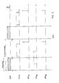
- the transmission signal of a typical MPRF radar consists of rectangular pulses. which also contain phase coding.
- the transmission pulse is binary phase-coded (+/-) after a code word with 20 codes, corresponding to a sub-pulse length of 1 ⁇ s.
- the received signals are sampled between two transmission pulses at sampling intervals the length of a sub-pulse.
- the samples p (t) are passed through a compression filter.
- the filter output signals can be further processed as echo signals sorted by distance gates, for which purpose the signals from a plurality of successive radar periods are subjected to Doppler processing. If the echo signal lies completely between two transmission pulses in the reception period, the result in FIG. 2 (b) sketched sample values p (t) A , which after correlation, for example with a matched filter in the pulse compression filter to the in FIG. 2 (c) lead filter output signal.
- This filter output signal provides a high value (main value) in a distance gate and a plurality of smaller values (secondary values) in neighboring distance gates.
- the main advantages of the MPRF radar are that the introduction of distance gates enables both the detection and distance measurement of tail aspect targets, but only in situations in which the echo signal of the target is in an (almost) clutter-free area the distance axis.
- neither the target distance nor the Doppler frequency can be clearly measured in the entire observation range with an MPRF radar.
- MPRF radar Another disadvantage of the MPRF radar is that the targets that fly towards the radar and that can be easily detected with an HPRF radar are often not detected in the MPRF radar because the high Doppler frequency contained in the echo signal is too great Malfunctions (up to complete suppression) in the pulse compression filter.
- MPRF and HPRF modes complement each other in target discovery and parameter estimation. But the advantages of the individual modes are limited to different target situations or applications. This fact is one of the reasons why today's on-board radars are often designed as multimode systems in order to achieve high system performance under all target aspect angles. On the other hand, switching between the different operating modes (MPRF and HPRF) in a multimode radar concept leads to considerable losses in the performance of the overall system.
- FIG. 4 transmit and receive signals of a pulse Doppler radar according to the invention are outlined.
- the rectangular pulses are additionally phase-coded from pulse to pulse, the same code being used for a clearer comparison word as selected for the MPRF radar.
- the individual square-wave pulses are isolated in time, so that there is a transmission-signal-free period between each two transmission pulses, in which a sample value is obtained from the received signal.
- the duty cycle from the pulse length ⁇ of the individual pulses and the pulse spacing PA is chosen to be 40%, as in the HPRF example, which results in the same performance in pure noise situations.
- VHPRF transmission signal s then consists of a sequence of individual pulses of length 100 ns with a pulse spacing of 250ns, the pulse sequence having a periodic pulse-to-pulse phase coding of the period duration 5 ⁇ s. Echo signal components reflected by a target then lead, when the received signals are scanned between two transmit pulses, to a sequence of samples which is likewise periodic with the duration of a radar period, ie with the length of a code word.
- the relative temporal position of the periodic sample sequence with respect to the periodic transmission pulse sequence depends on the target distance, so that conversely, by determining this relative temporal position by means of pulse compression of the periodic sample sequence, information about the target distance can be obtained.
- the range uniqueness range is 750 m and the range resolution is 15 m. It is easy to see that a range uniqueness range of 750 m with a radar range of around 100 km does not yet allow a reasonable statement to be made about the actual target distance.
- the correlation of the periodic sample sequence with the filter function of the pulse compression filter in turn leads to a periodic correlation function as a filter output signal.
- the filter can be designed as a matched filter or as a mismatched filter.
- 2 is not equal to zero.
- the associated DFT spectrum with the spectral coefficients is advantageously obtained in a first step by means of the discrete Fourier transformation and by multiplying by the conjugate complex value Z also the amount squares of the spectral coefficients determined. If for all n applies
- the problem of eclipsing which has already been described, also arises with the VHPRF pulse Doppler radar according to the invention.
- the sequence of sample values that results from the sampling is entered for a signal situation with undetected (b) and half-covered (c) echo signals.
- an echo pulse is entered in its relative temporal position with respect to the first transmission pulse of the signal section shown.
- the echo pulse corresponding to the first transmit pulse of a code word is highlighted in the sample value sequences.
- there are also different signal propagation times i.e. different target distances.
- the partial masking of a rectangular pulse leads to a lower amplitude of the sample value compared to the eclipsing-free situation. It is essential in the present case, however, that the phase relationships are completely retained even in the case of partial masking and are included in the (complex) sample values. Since there is no measurable change in the eclipsing situation within a radar period (5 ⁇ s), the resulting reduction in amplitude is the same for all samples. Since the phase relationships are preserved, the coding of the sample sequence remains complete. With pulse compression, this means that only all values of the filter output signal are linearly reduced.
- FIG. 5 (b) and (d) are those shown in FIG. 4 (b) and (c) shown sample value sequences p (t) AV and p (t) BV entered over a reception period of more than two radar periods, and each below which results when correlated with the mismatched filter function (FIG. 5 (a)) Filter output signals, each repeating a main value at intervals of one radar period with, as provided, within the radar period different time positions and, as expected by the eclipsing situation for p (t) BV , different amplitudes of the main values.
- the special selection of the filter coefficients means that all secondary values in the filter output signal disappear, which is easy to see, which is particularly advantageous for the application.
- the N partial intervals of the radar periods for the filter output signals represent distance gates Echo signals originating from a true radar target with generally little extension then lead to significant values in the filter output signal only in one or a few distance gates.
- the unchanged high duty cycle leads to a consistently large target detection range in noise and the introduction of range gates leads to an improvement in the S / C ratio and thus to an increase in the target detection probability in the clutter.
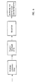
- FIG. 6 shows the essential signal processing stages in block diagram form.
- the received signal is a complex periodic signal that is only time-delayed and possibly Doppler frequency-modulated compared to the transmitted signal with the signal shown in FIG. 4 explained basic structure.
- the echoes of many reflection objects additively overlap in the received signal as target echoes and false echoes as well as noise.
- the received signal is separated into signal components divided into different distance gates.
- the N complex values assigned to the individual range gates per radar period are sorted by range gates, so that M complex values are separately available for a coherent processing interval (CPI) encompassing M radar periods for N range gates.
- CPI coherent processing interval
- the M values are subjected to Doppler signal processing for target detection and determination of the target Doppler frequency.
- the Doppler signal processing is carried out according to the method also used in the HPRF radar, for example using the fast Fourier transform (FFT) on the value group within corresponding distance gates. Due to the division into distance gates, there is also high-resolution but ambiguous distance information for the targets detected in Doppler signal processing. Switching the radar period from CPI to CPI results in different, ambiguous range values, from which a clear target range is determined over a wide range using known methods (e.g. / 3,4 /).
- the sketch according to FIG. 7 illustrates that the N output values of the pulse compression filter PKF occurring per radar period are successively allocated to the N range gates.
- the series of distance gates is run through again and a filter output value is allocated in each case, so that a field of complex values sorted in distance and time arises.
- Each value series forms a time signal from discrete values at intervals of one radar period.
- this time signal with M values is transformed into a Doppler frequency spectrum with M discrete values by means of an FFT process.
- the echo signals originating from a target echo appear in the value field of the time signals in the entire value series of a distance gate (hatched), but only in a value of the value field formed by the N spectra.
- the FFT can be carried out for all distance gates in parallel or in time multiplex.
Abstract
Description
Die Erfindung betrifft ein Pulsdopplerradar der im Oberbegriff des Patentanspruchs 1 angegebenen Art.The invention relates to a pulse Doppler radar of the type specified in the preamble of
Bei einem Pulsdopplerradar mit intervallweise kohärenter Signalverarbeitung kann durch kohärente Integration der innerhalb eines sogenannten CPI (coherent processing interval) empfangenen Echosignale eine eventuelle Dopplerfrequenzverschiebung fD der Echosignale gemessen und daraus eine Aussage über die Radialgeschwindigkeit eines Ziels abgeleitet werden. Der Dopplerfrequenzbereich
In Bodenradarsystemen, z.B. für die Flugüberwachung, werden Sendesignale mit periodisch wiederholten einfachen Rechteck- oder codierten Impulsen eingesetzt. Das charakteristische Merkmal für Bodenradare ist aber eine relativ geringe und i.a. konstante PRF (ca. 1 kHz), so daß die praktisch auftretenden Zielentfernungen mit dem Radar eindeutig gemessen werden. Die Echosignale der Nutzziele konkurrieren bei diesen LPRF Radaren ausschließlich mit dem in der jeweiligen Radarzelle vorkommenden Bodenclutter. Durch eine zeitabhängige Regelung (STC) im Radarempfänger kann der mit hohen Amplituden auftretende Nahebereichsclutter gedämpft werden, ohne dadurch gleichzeitig die Amplituden in den Echosignalen und damit die Entdeckbarkeit weit entfernter Ziele zu reduzieren. In clutterfreien Gebieten des Beobachtungsbereiches ist die Zielentdeckung deshalb lediglich durch das Empfängerrauschen begrenzt.In ground radar systems, for example for flight monitoring, transmission signals with periodically repeated simple rectangular or coded pulses are used. The characteristic feature for ground radars is a relatively low and generally constant PRF (approx. 1 kHz), so that the practically occurring target distances can be clearly measured with the radar. With these LPRF radars, the echo signals of the useful targets only compete with the ground clutter found in the respective radar cell. A time-dependent control (STC) in the radar receiver can dampen the proximity clutter that occurs with high amplitudes without simultaneously reducing the amplitudes in the echo signals and thus reducing the detectability of distant targets. In clutter-free areas of the observation area the target discovery is therefore only limited by the receiver noise.
Bordradarsysteme sind dagegen häufig als sogenannte Multimode-Pulsdopplerradare konzipiert /1.2/. Die Sendesignale sind ebenfalls wie beim Bodenradar aus periodisch wiederholten einfachen Rechteck- oder codierten Impulsen aufgebaut, aber die benutzten Pulsfolgefrequenzen beschränken sich hier nicht auf den LPRF-Bereich (ca. 1 kHz) sondern MPRF (10 - 20 kHz) und HPRF (ca. 200 kHz), werden in Abhängigkeit der jeweiligen Aufgabe (Zielsuche, Trackung) ebenfalls und wechselseitig eingesetzt.On-board radar systems, however, are often designed as so-called multimode pulse Doppler radars /1.2/. As with ground radar, the transmission signals are made up of periodically repeated simple square-wave or coded pulses, but the pulse repetition frequencies used are not limited to the LPRF range (approx. 1 kHz) but MPRF (10 - 20 kHz) and HPRF (approx. 200 kHz), are also used and mutually depending on the respective task (target search, tracking).
Im Gegensatz zu LPRF-Bodenradaren wird die Zielentfernung im HPRF- bzw. MPRF-Radar nicht oder nicht eindeutig gemessen. Wegen der dabei auftretenden Entfernungsmehrdeutigkeiten wird i.a. keine STC-Regelung in diesen Modi eingesetzt. In diesen Situationen sind aber die Reflexionen an der Erdoberfläche, die über die Antennennebenkeulen in den Empfänger gelangen (Nebenkeulenclutter), i.a nicht mehr vernachlässigbar, sondern hben eine relativ hohe Echoamplitude. Diese Tatsache führt einerseits unmittelbar zu hohen Anforderungen an die Antennennebenzipfel für Bordradare. Andererseits gewinnt das Problem der Clutter- und Nutzsignaltrennung mit Methoden der digialen Signalverarbeitung durch den Nahbereichs- und Nebenkeulenclutter für MPRF- und HPRF-Radare zusätzlich an Bedeutung.In contrast to LPRF ground radars, the target range is not or not clearly measured in the HPRF or MPRF radar. Because of the distance ambiguities that arise, i.a. no STC control used in these modes. In these situations, however, the reflections on the earth's surface that reach the receiver via the side lobes of the antenna (side lobe clutter) are no longer negligible, but rather have a relatively high echo amplitude. On the one hand, this fact leads to high demands on the antenna sub-peaks for on-board radars. On the other hand, the problem of clutter and useful signal separation using methods of digital signal processing by the short-range and side lobe clutter for MPRF and HPRF radars is becoming increasingly important.
Aufgabe der vorliegenden Erfindung ist daher, ein als Flugzeug-Bordradar mit eindeutiger Zielgeschwindigkeitsmessung geeignetes Pulsdopplerradar anzugeben, mit welchem eine verbesserte Zielentdeckung und Zielparameterschätzung möglich ist.The object of the present invention is therefore to provide a pulse Doppler radar suitable as an aircraft on-board radar with unambiguous target speed measurement, with which one improved target discovery and target parameter estimation is possible.
Die Erfindung ist im Patentanspruch 1 beschrieben. Die Unteransprüche enthalten vorteilhafte Ausführungen und Weiterbildungen der Erfindung.The invention is described in
Zum Vergleich des erfindungsgemäßen Pulsdopplerradars mit bekannten Radaren sei im folgenden als bekanntes System ein HPRF-Radar mit weitgehend eindeutiger Dopplerfrequenzbestimmung zugrunde gelegt und für die Systemparameter eines Ausführungsbeispiels der Erfindung derselbe Dopplerfrequenz-Eindeutigkeitsbereich angenommen. Bei dem erfindungsgemäßen Radar ist die für den Dopplereindeutigkeitsbereich maßgebende Größe die Periodendauer T, so daß die Folgefrequenz der einzelnen Pulse um den Faktor N höher liegt als beim gebräuchlichen HPRF-Radar. Das erfindungsgemäße Pulsdoppleradar ist daher im folgenden kurz mit VHPRF (very high pulse repetition frequency)-Radar bezeichnet.In order to compare the pulse Doppler radar according to the invention with known radars, an HPRF radar with a largely unambiguous Doppler frequency determination is used as the known system in the following and the same Doppler frequency uniqueness range is assumed for the system parameters of an embodiment of the invention. In the radar according to the invention, the variable that is decisive for the Doppler uniqueness range is the period T, so that the repetition frequency of the individual pulses is higher by a factor N than in the conventional HPRF radar. The pulse doubler radar according to the invention is therefore briefly referred to below as VHPRF (very high pulse repetition frequency) radar.
Sowohl das konventionelle HPRF-Radar wie auch das VHPRF-Radar gestatten eine sehr genaue und eindeutige Messung der Radialgeschwindigkeit entdeckter Nutzziele.Both the conventional HPRF radar and the VHPRF radar allow a very precise and unambiguous measurement of the radial speed of discovered usage targets.
Die Einführung von Entfernungstoren ergibt auch noch nicht ohne weiteres einen Wert für die Zielentfernung, da die Entfernungstorinformation vieldeutig ist. Es besteht insoweit daher noch kein Anlaß, die Pulsfolgefrequenz gegenüber dem gebräuchlichen HPRF-Radar noch weiter zu erhöhen. Als wesentlicher Vorteil des VHPRF-Radars ergibt sich aber zum einen, daß das Signal/Clutter-Verhältnis innerhalb der ein zelnen Entfernungstore wesentlich verbessert und dadurch die Zielentdeckungswahrscheinlichkeit bei der nachfolgenden entfernungstorweisen Dopplerverarbeitung deutlich erhöht wird, so daß auch Ziele unter ungünstigen Zielaspektwinkeln. die beim HPRF-Radar von Clutter bedeckt sind, noch entdeckt werden. Zum anderen kann durch Umschaltung der Periodendauer von Intervall zu Intervall und Vergleich der bei unterschiedlichen Periodendauern jeweils vieldeutig gemessenen Zielentfernungen eine über einen großen Entfernungsbereich eindeutige Zielentfernung geschätzt werden. Die sehr hohe Entfernungsauflösung durch die einzelnen Entfernungstore kann u.U. auch als detaillierte Zielinformation zur Zielklassifikation herangezogen werden. Darüber hinaus wird durch die Codierung die Störfestigkeit gegenüber bestimmten Methoden zur absichtlichen Störung erhöht, wozu auch noch die Codierung von Intervall zu Intervall gewechselt werden kann.The introduction of range gates does not yet easily give a value for the target range, since the range gate information is ambiguous. There is therefore no reason to increase the pulse repetition frequency even further compared to the usual HPRF radar. One of the main advantages of the VHPRF radar is that the signal / clutter ratio is within the one individual distance gates are significantly improved and the probability of target detection in the subsequent distance gate-wise Doppler processing is significantly increased, so that targets under unfavorable target aspect angles. that are covered by clutter on the HPRF radar can still be discovered. On the other hand, by switching the period from interval to interval and comparing the target distances measured ambiguously for different periods, a clear target distance can be estimated over a large distance range. The very high range resolution by the individual range gates can also be used as detailed target information for target classification. In addition, the coding increases the immunity to interference from certain methods of deliberate interference, for which the coding can also be changed from interval to interval.
Das Tastverhältnis (duty cycle) kann beim VHPRF-Radar wie beim HPRF-Radar gewählt und z.B. auf 40 % eingestellt werden. Dies bedeutet auch, daß im Mittel dieselbe Leistung abgestrahlt wird. Der Effekt des sogenannten Eclipsing, d.h. die teilweise oder vollständige Verdeckung eines Echopulses durch einen Sendepuls, tritt beim HPRF- und beim VHPRF-Radar auf, wobei sich aber in diesem Fall die sehr kurze Pulslänge des VHPRF-Radars dadurch vorteilhaft auswirkt, daß ein durch Eclipsing verdeckter Echopulszug eines Zielechos durch die Relativbewegung von Radaranlage und Ziel nach kürzerer Zeit wieder soweit in den Empfangs-Zeitabschnitt verschoben ist, daß eine zur Zielentdeckung ausreichende Empfangsleistung zur Verfügung steht. Die Pulsfolgefrequenz des HPRF-Radars ist aufgrund der Forderung nach immer eindeutiger Bestimmung der Dopplerfrequenz und damit der Radialgeschwindigkeit eines Ziels bestimmt durch die maximal zu erwartende relative Zielgeschwindigkeit, die in der Situation eines direkt entgegenfliegenden Ziels auftritt (Head-on-Aspekt). Die Pulswiederholfrequenz eines HPRF-Radars liegt daher im Bereich über 100 kHz, typischerweise um 200 kHz. Für den gleichen Geschwindigkeitseindeutigkeitsbereich ist beim VHPRF-Radar die Periodendauer T entsprechend kleiner als 10µs, typischerweise ca. 5µs, zu wählen. Die Pulsfolgefrequenz beim VHPRF-Radar ist gegenüber dem HPRF-Radar dann um den Faktor N (mit N als Codelänge des von Radarperiode zu Radarperiode wiederholten Codeworts) höher. Bei den z.Zt. gebräuchlichen Radarsendern mit zentraler Erzeugung der Sendeleistung und Verteilung auf eine Vielzahl von Strahlerelementen einer Gruppenantenne begrenzt die Erholungszeit des Senders die Pulsfolgefrequenz und damit die Codelänge. Vorzugsweise ist daher eine Sendeantenne mit einer Vielzahl aktiver. Halbleiterbauteile enthaltender Strahlerelemente vorgesehen, die nur sehr kurze Erholungszeiten aufweisen.The duty cycle can be selected with the VHPRF radar as with the HPRF radar and set to 40%, for example. This also means that the same power is emitted on average. The effect of so-called eclipsing, ie the partial or complete masking of an echo pulse by a transmission pulse, occurs with the HPRF and VHPRF radar, but in this case the very short pulse length of the VHPRF radar has the advantageous effect that a through Eclipsing concealed echo pulse train of a target echo due to the relative movement of the radar system and target after a shorter time is again so far shifted into the reception period that sufficient reception power is available for target detection. The pulse repetition rate of the HPRF radar is based on the requirement for a clear determination of the Doppler frequency and thus the radial speed of a target by the maximum expected relative target speed that occurs in the situation of a directly opposing target (head-on aspect). The pulse repetition frequency of an HPRF radar is therefore in the range above 100 kHz, typically around 200 kHz. For the same speed unambiguity range, the period T should be chosen correspondingly less than 10µs, typically about 5µs, for the VHPRF radar. The pulse repetition frequency in the VHPRF radar is then higher by a factor of N than the HPRF radar (with N as the code length of the code word repeated from radar period to radar period). At the moment In common radar transmitters with central generation of the transmission power and distribution over a large number of antenna elements of a group antenna, the recovery time of the transmitter limits the pulse repetition frequency and thus the code length. A transmitting antenna with a multiplicity is therefore preferably active. Semiconductor components containing radiator elements are provided, which have only very short recovery times.
Die Erfindung ist im folgenden anhand von Beispielen und unter Bezugnahme auf die Abbildungen noch eingehend veranschaulicht und bekannten Pulsdopplerradars gegenübergestellt. Es zeigt
- FIG. 1 Sende- und Empfangssignale eines LPRF-Radars.
- FIG. 2 Sende- und Empfangssignale im MPRF-Modus.
- FIG. 3 Sende- und Empfangssignale im HPRF-Modus.
- FIG. 4 Sende- und Empfangssignale im VHPRF-Modus.
- FIG. 5 eine spezielle Kombination von Codierung und Kompressionsfilterfunktion sowie Filtereingangs- und -ausgangssignale.
- FIG. 6 ein Blockschaltbild der aufeinanderfolgenden Signalverarbeitungsstufen.
- FIG. 7 eine schematische Darstellung des Zusammenwirkens von Pulskompression und Dopplerverarbeitung.
- FIG. 1 Transmit and receive signals of an LPRF radar.
- FIG. 2 transmit and receive signals in MPRF mode.
- FIG. 3 transmit and receive signals in HPRF mode.
- FIG. 4 transmit and receive signals in VHPRF mode.
- FIG. 5 a special combination of coding and compression filter function as well as filter input and output signals.
- FIG. 6 shows a block diagram of the successive signal processing stages.
- FIG. 7 shows a schematic illustration of the interaction of pulse compression and Doppler processing.
Bei den mit niedriger Pulsfolgefrequenz (LPRF) arbeitenden Bodenradaren wird als Sendesignal s(t) zu Beginn einer Radarperiode ein leistungsstarker kurzer Sendepuls von typischerweise 1 µs Pulsdauer abgestrahlt (FIG. 1. (a)). Während der nachfolgenden Empfangsphase werden aus dem Empfangssignal e(t) in Abtastintervallen, die Entfernungstoren zugeordnet sind, Abtastwerte gewonnen. Bei einer tvpischen Pulsfolgefrequenz von 1 kHz und damit einer Periodendauer von 1ms ergibt sich ein eindeutiger Entfernungsbereich von 150 km. Eine Aufteilung der Empfangszeit in 10³ Abtastintervalle ergibt eine Entfernungsauflösung von 150 m. Da die Länge der Abtastintervalle in gleicher Größenordnung wie die Pulsdauer liegen, erscheint ein Zielechoimpuls im Empfangsignal e(t) nur in einem oder wenigen Entfernungstoren und die Zielentfernung kann eindeutig gemessen werden (FIG. 1. (b)). Eine Information über die Geschwindigkeit eines Ziels kann durch Auswertung mehrerer aufeinanderfolgender Radarperioden (Burst) mehrdeutig, durch Wechsel der PRF und Vergleich von Bursts mit unterschiedlicher PRF schließlich auch eindeutig gewonnen werden.In the case of the ground radars operating with a low pulse repetition frequency (LPRF), a powerful short transmission pulse of typically 1 μs pulse duration is emitted as the transmission signal s (t) at the beginning of a radar period (FIG. 1 (a)). During the subsequent reception phase, sampling values are obtained from the reception signal e (t) in sampling intervals which are associated with distance gates. With a typical pulse repetition frequency of 1 kHz and thus a period of 1 ms, there is a clear distance range of 150 km. A division of the reception time into 10³ sampling intervals results in a distance resolution of 150 m. Since the length of the sampling interval is of the same order of magnitude as the pulse duration, a target echo pulse appears in the received signal e (t) only in one or a few distance gates and the target distance can be measured uniquely (FIG. 1 (b)). Information about the speed of a target can be obtained ambiguously by evaluating several successive radar periods (burst), and finally by changing the PRF and comparing bursts with different PRF.
Demgegenüber ist bei Bordradarsystemen die Zielgeschwindigkeit ein wichtiges Unterscheidungsmerkmal zwischen Zielen und Clutter. Außerdem steht nur eine vergleichweise geringe Sendeleistung zur Verfügung, so daß die Sendesignalform des LPRF-Radars nicht übernommen werden kann. Nachfolgend sind daher auch Beispiele für die bei Bordradar gebräuchlichen Betriebsarten mit mittlerer (MPRF, FIG. 2) und hoher (HPRF. FIG. 3) Pulsfolgefrequenz beschrieben.In contrast, in on-board radar systems, the target speed is an important distinguishing feature between targets and clutter. In addition, only a comparatively low transmission power is available, so that the transmission signal form of the LPRF radar cannot be adopted. Examples of the modes of operation with medium (MPRF, FIG. 2) and high (HPRF. FIG. 3) which are common for on-board radar are therefore also described below.
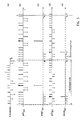
Das Sendesignal eines typischen HPRF-Radars (FIG. 3, (a)) besteht aus einfachen Rechteckimpulsen (z.B. Pulslänge τ = 2µs), die bei fester Sendefrequenz in sehr kurzen Zeitabständen (Pulsabstand PA = Dauer T einer Radarperiode = 5µs bei 200 kHz PRF) periodisch wiederholt werden. Das resultierende Tastverhältnis
TV = τ/PA
ist in diesem als Beispiel anzusehenden HPRF-Sendesignal gleich 40 %.The transmission signal of a typical HPRF radar (FIG. 3, (a)) consists of simple rectangular pulses (eg pulse length τ = 2µs) which, at a fixed transmission frequency, occur in very short time intervals (pulse interval PA = duration T of a radar period = 5µs at 200 kHz PRF ) are repeated periodically. The resulting duty cycle
TV = τ / PA
is 40% in this exemplary HPRF transmission signal.
Das zugehörige Echosignal e(t) (Fig. 3, (b)) wird im Radarempfänger mit einem Puls-Matched-Filter verarbeitet und in jeder Radarperiode ein- oder zweimal (entsprechend der Signalbandbreite) abgetastet. Die in einer Vielzahl aufeinanderfolgender Radarperioden gewonnenen Abtastwerte werden einer Dopplerverarbeitung zur Zielentdeckung und zur Schätzung der Zielgeschwindigkeit unterzogen. In diesem Fall entstehen keine Informationen über die Zielentfernung. Mehrzielsituationen können dann nur über die Radialgeschwindigkeit aufgelöst werden.The associated echo signal e (t) (Fig. 3, (b)) is processed in the radar receiver with a pulse-matched filter and sampled once or twice (according to the signal bandwidth) in each radar period. The samples obtained in a plurality of successive radar periods are subjected to Doppler processing for target detection and for estimating the target speed. In this case, there is no information about the target distance. Multi-target situations can then only be resolved via the radial speed.
Durch das Tastverhältnis von 40 % liegen die Echosignale nur mit geringer Wahrscheinlichkeit vollständig in den Empfangsabschnitten zwischen je zwei Sendeimpulsen (FIG. 3, (b), Empfangssignal e(t)A). Überwiegend sind die Zielechosignale teilweise von den Sendesignalen verdeckt, was als Eclipsing bezeichnet wird. Eine Situation mit einem teilweise verdeckten Echosignal e(t)B in FIG. 3 (d) skizziert, der verdeckte Teil des Echosignals ist als unterbrochene Linie angedeutet. Entsprechend der geringeren Echosignalenergie im Abtastzeitraum sind die im Fall der FIG. 3 (d) gewonnenen Abtastwerte p(t)B (FIG. 3 (e)) schwächer als die aus dem unverdeckten Echosignal e(t)A gewonnenen Abtastwerte p(t)A in FIG. 3, (c). Da der Rauschanteil im Empfangssignal in beiden Fällen als gleich anzunehmen ist, ist offensichtlich, daß die Zielentdeckung mit zunehmendem Eclipsing schwieriger wird.Due to the duty cycle of 40%, the echo signals are only with a low probability completely in the receive sections between two transmit pulses (FIG. 3, (b), receive signal e (t) A ). The target echo signals are predominantly partially covered by the transmission signals, which is referred to as eclipsing. A situation with a partially hidden echo signal e (t) B in FIG. 3 (d) outlines that the hidden part of the echo signal is indicated as a broken line. In accordance with the lower echo signal energy in the sampling period, those in the case of FIG. 3 (d) obtained samples p (t) B (FIG. 3 (e)) from the weaker than the unobstructed echo signal e (t) A sample obtained p (t) A in FIG. 3, (c). Since the noise component in the received signal can be assumed to be the same in both cases, it is obvious that the target discovery becomes more difficult with increasing eclipsing.
Bodenclutterechos, die über die Antennenhaupt- oder -nebenkeulen in den Radarempfänger gelangen, machen sich beim HPRF-Bordradar im Dopplerfrequenzbereich bis zur Eigengeschwindigkeit des Radars über Grund bemerkbar. Das einzige Unterscheidungsmerkmal zwischen Bodenclutter und Nutzzielen ist dann also die Dopplerfrequenz, so daß weit entfernte (schwache) Nutzziele i.a. nur im clutterfreien Bereich auf der Dopplerfrequenzachse entdeckt werden können und das sind Flugziele, die sich auf das Radar zubewegen (Head on Aspect). Durch eine kohärente Signalauswertung können solche Nutzziel- und Clutterechos vollständig voneinander getrennt und dadurch das Detektionsproblem auf eine relativ einfache Zielentdeckung im Rauschen reduziert werden.Ground clutter echoes that reach the radar receiver via the antenna main or side lobes are noticeable in the HPRF on-board radar in the Doppler frequency range up to the speed of the radar above ground. The only distinguishing feature between ground clutter and useful targets is then the Doppler frequency, so that distant (weak) useful targets can generally only be discovered in the clutter-free area on the Doppler frequency axis and these are flight targets that move towards the radar (head on aspect). With a coherent signal evaluation, such useful target and clutter echoes can be completely separated from one another, thereby reducing the detection problem to a relatively simple target detection in noise.
In der Zielsuchphase legen Bordradarsysteme i.a. den Schwerpunkt auf eine eindeutige Dopplerfrequenzschätzung, weil die jeweilige Zielgeschwindigkeit ein wichtiges Erkennungs- und Unterscheidungsmerkmal zwischen Flug- und z.B. Störobjekten (Clutter) ist. Mit dem oben beschriebenen Sendesignal und einem X-Band-Radar können Radialgeschwindigkeiten heutiger Flugzeuge eindeutig gemessen werden. Wegen des hohen Tastverhältnisses (TV) und dem daraus resultierenden Integrationsgewinn in der digitalen Signalverarbeitung (Dopplerfilterbank, FFT) entsteht eine große Zielentdeckungsreichweite für die auf das Radar zufliegenden Ziele. Allerdings wird mit dem HPRF-Radar keine Information über die jeweilige Zielentfernung gemessen.In the target search phase, on-board radar systems generally the focus on a clear Doppler frequency estimate, because the respective target speed is an important recognition and differentiator between flight and e.g. Interfering objects (clutter). With the transmission signal described above and an X-band radar, radial speeds of today's aircraft can be clearly measured. Because of the high duty cycle (TV) and the resulting gain in integration in digital signal processing (Doppler filter bank, FFT), there is a large target detection range for the targets flying towards the radar. However, no information about the respective target distance is measured with the HPRF radar.
Echosignale der Ziele, die sich vom Radar wegbewegen (Tail Aspect), überlagern sich additiv mit den gleichzeitig aus dem Nahbereich über die Antennennebenkeulen empfangenen (relativ starken) Bodenclutterechos, befinden sich also mit anderen Worten nicht im clutterfreien Bereich auf der Dopplerfrequenzachse und werden mit dem hier skizzierten HPRF-Radar und bei weit entfernten (schwachen) Zielen aufgrund des i.a. niedrigen Signal-zu-Clutter(S C)-Verhältnisses nicht oder nur mit geringer Wahrscheinlichkeit entdeckt. Wegen dieser wesentlichen Einschränkung beim HPRF-Radar ist bei Bordradaren üblicherweise zusätzlich die Betriebsart mit mittlerer Pulsfolgefrequenz vorgesehen.Echo signals of the targets moving away from the radar (Tail Aspect), additively overlap with the (relatively strong) ground clutter echoes simultaneously received from the close range via the antenna sidelobes, i.e. in other words they are not in the clutter-free range on the Doppler frequency axis and become with the here sketched HPRF radar and at distant (weak) targets due to the ia low signal-to-clutter (S C) ratio not detected or only with a low probability. Because of this significant limitation in the HPRF radar, the operating mode with medium pulse repetition frequency is usually additionally provided for on-board radars.
Das Sendesignal eines typischen MPRF-Radars besteht aus rechteckförmigen Impulsen. die zusätzlich eine Phasencodierung enthalten. Als Beispiel ist in FIG. 2 ein MPRF-Sendesignal s(t) mit einer Pulswiederholfrequenz von 10 kHz entsprechend einem Pulsabstand von 100µs und einer Pulslänge von 20µs angenommen, was ein Tastverhältnis (duty cycle) von 20 % bedeutet.The transmission signal of a typical MPRF radar consists of rectangular pulses. which also contain phase coding. As an example, in FIG. 2 an MPRF transmission signal s (t) with a pulse repetition frequency of 10 kHz corresponding to a pulse interval of 100µs and a pulse length of 20µs, which means a duty cycle of 20%.
Der Sendeimpuls ist binär phasencodiert (+/-) nach einem Codewort mit 20 Codestellen entsprechend einer Subpulslänge von 1µs. Die Empfangssignale werden zwischen zwei Sendeimpulsen in Abtastintervallen von der Länge eines Subpulses abgetastet. Die Abtastwerte p(t) werden über ein Kompressionsfilter geführt. Die Filterausgangssignale können als nach Entfernungstoren sortierte Echosignale weiterverarbeitet werden, wozu wiederum die Signale aus einer Mehrzahl aufeinanderfolgender Radarperioden einer Dopplerverarbeitung- unterzogen werden. Falls das Echosignal vollständig in dem Empfangszeitraum zwischen zwei Sendepulsen liegt, ergeben sich die in FIG. 2 (b) skizzierten Abtastwerte p(t)A, die nach Korrelation z.B. mit einem Matched-Filter im Pulskompressionsfilter zu dem in FIG. 2 (c) dargestellten Filterausgangssignal führen. Dieses Filterausgangssignal liefert einen hohen Wert (Hauptwert) in einem Entfernungstor und eine Mehrzahl kleinerer Werte (Nebenwerte) in benachbarten Entfernungstoren.The transmission pulse is binary phase-coded (+/-) after a code word with 20 codes, corresponding to a sub-pulse length of 1µs. The received signals are sampled between two transmission pulses at sampling intervals the length of a sub-pulse. The samples p (t) are passed through a compression filter. The filter output signals can be further processed as echo signals sorted by distance gates, for which purpose the signals from a plurality of successive radar periods are subjected to Doppler processing. If the echo signal lies completely between two transmission pulses in the reception period, the result in FIG. 2 (b) sketched sample values p (t) A , which after correlation, for example with a matched filter in the pulse compression filter to the in FIG. 2 (c) lead filter output signal. This filter output signal provides a high value (main value) in a distance gate and a plurality of smaller values (secondary values) in neighboring distance gates.
Wenn jedoch das Echosignal teilweise durch einen Sendepuls verdeckt ist (Eclipsing), so ergibt sich bei den aus dem Empfangssignal gewonnenen Abtastwerten p(t)B nur noch ein verstümmeltes Codewort. Eine solche Situation mit einer Verdeckung von 50 % zeigt FIG. 2 (d). Die den vom Sendesignal verdeckten Echosignalanteilen entsprechenden fehlenden Abtastwerte sind durch unterbrochene Linien und offene Kreise angedeutet. Das zugehörige Ausgangssignal des Puls kompressionsfilters zeigt FIG. 2 (e). Neben der verringerten Zielentdeckungswahrscheinlichkeit wegen des niedrigeren Hauptwertes des komprimierten Signals ergeben sich gravierende Probleme durch die bei Kompression des nicht vollständigen Echosignals stark anwachsenden Nebenwerte im komprimierten Signal, die zu Falschzielmeldungen in anderen Entfernungstoren führen können. Die Wahrscheinlichkeit für Eclipsing-Situationen steigt mit zunehmendem Tastverhältnis. Üblicherweise wird daher bei MPRF-Radaren, abweichend vom skizzierten Beispiel, ein geringeres Tastverhältnis gewählt. Für den Bereich in der ersten Hälfte des Sendeimpulses werden wegen des schlechten Kompressionsergebnisses in der Regel überhaupt keine Werte für r(t) gebildet.If, however, the echo signal is partially covered by a transmit pulse (eclipsing), then only a garbled code word results in the sample values p (t) B obtained from the received signal. Such a situation with a coverage of 50% is shown in FIG. 2 (d). The missing sampling values corresponding to the echo signal components hidden by the transmission signal are indicated by broken lines and open circles. The associated output signal of the pulse compression filter shows FIG. 2 (e). In addition to the reduced probability of target detection due to the lower main value of the compressed signal, serious problems result from the secondary values in the compressed signal which increase strongly when the incomplete echo signal is compressed, which can lead to false target messages in other distance gates. The likelihood of eclipsing situations increases with increasing duty cycle. Usually, a lower duty cycle is therefore chosen for MPRF radars, in contrast to the example outlined. Because of the poor compression result, no values for r (t) are generally formed for the area in the first half of the transmission pulse.
Die Unterscheidung von Nutzziel- und Clutterechosignalen kann im MPRF-Radar auch aufgrund der jeweiligen Objektentfernung vorgenommen werden, ein Unterscheidungsmerkmal, das im HPRF-Radar i.a. nicht gemessen und ausgewertet wird. Aber allein aufgrund des wesentlich geringeren Tastverhältnisses im MPRF-Radar verringert sich die Zielentdeckungsreichweite im Rauschen.The distinction between useful target and clutter echo signals can also be made in the MPRF radar on the basis of the respective object distance, a distinguishing feature that is generally found in the HPRF radar. is not measured and evaluated. But just because of the much lower duty cycle in the MPRF radar, the target detection range in the noise is reduced.
Die wesentlichen Vorteile des MPRF-Radars bestehen darin, daß durch die Einführung von Entfernungstoren sowohl eine Entdeckung und Entfernungsmessung von Tail-Aspekt-Zielen möglich ist, allerdings nur in den Situationen, in denen das Echosignal des Nutzzieles in einem (fast) clutterfreien Bereich auf der Entfernungsachse liegt. Andererseits kann mit einem MPRF-Radar weder die Zielentfernung noch die Dopplerfrequenz im gesamten Beobachtungsbereich eindeutig gemessen werden. In beiden Koordinaten treten Mehrdeutigkeiten auf, die durch die PRF-Festlegung bestimmt sind. Diese Mehrdeutigkeiten auf der Entfernungs- und/oder Dopplerfre quenzachse können mit Signalverarbeitungstechniken wieder aufgelöst werden, wenn das Ziel (die Ziele) in benachbarten Signalblöcken (CPI) mit gering unterschiedlicher PRF entdeckt wurde(n). Ein weiterer Nachteil des MPRF-Radars besteht darin, daß die Nutzziele, die auf das Radar zufliegen und die mit einem HPRF-Radar problemlos entdeckt werden können, im MPRF-Radar häufig nicht entdeckt werden, weil die im Echosignal enthaltene hohe Dopplerfrequenz zu extrem großen Störungen (bis hin zur vollständigen Ausblendung) im Pulskompressionsfilter führen kann.The main advantages of the MPRF radar are that the introduction of distance gates enables both the detection and distance measurement of tail aspect targets, but only in situations in which the echo signal of the target is in an (almost) clutter-free area the distance axis. On the other hand, neither the target distance nor the Doppler frequency can be clearly measured in the entire observation range with an MPRF radar. There are ambiguities in both coordinates, which are determined by the PRF definition. This ambiguity on the distance and / or Dopplerfre Quenzachse can be resolved again with signal processing techniques if the target (s) were found in neighboring signal blocks (CPI) with slightly different PRF (s). Another disadvantage of the MPRF radar is that the targets that fly towards the radar and that can be easily detected with an HPRF radar are often not detected in the MPRF radar because the high Doppler frequency contained in the echo signal is too great Malfunctions (up to complete suppression) in the pulse compression filter.
Im Sinne der obigen Systembeurteilung ergänzen sich MPRF und HPRF Modi bei der Zielentdeckung und Parameterschätzung. Aber die Vorteile der einzelnen Modi beschränken sich auf unterschiedliche Zielsituationen bzw. Anwendungen. Diese Tatsache ist mit ein Grund dafür, daß heutige Bordradare häufig als Multimode-Systeme aufgebaut sind, um somit eine hohe Leistungsfähigkeit des Systems unter allen Zielaspektwinkeln zu erzielen. Andererseits führt die Umschaltung zwischen den verschiedenen Betriebsarten (MPRF und HPRF) bei einem Multimode-Radarkonzept zu nicht unerheblichen Verlusten in der Leistungsfähigkeit des Gesamtsystems.In terms of the above system assessment, MPRF and HPRF modes complement each other in target discovery and parameter estimation. But the advantages of the individual modes are limited to different target situations or applications. This fact is one of the reasons why today's on-board radars are often designed as multimode systems in order to achieve high system performance under all target aspect angles. On the other hand, switching between the different operating modes (MPRF and HPRF) in a multimode radar concept leads to considerable losses in the performance of the overall system.
In FIG. 4 sind Sende- und Empfangssignale eines erfindungsgemäßen Pulsdopplerradars skizziert. Dabei wird eine Radarperiode, die im Beispiel wie beim HPRF-Radar (FIG. 3) die Länge T = 5µs habe, äquidistant in N Teilintervalle unterteilt und in jedem Teilintervall ein Rechteckimpuls sehr geringer Länge (entsprechend hoher Bandbreite) abgestrahlt. Die Rechteckimpulse sind zusätzlich von Puls zu Puls phasencodiert, wobei zum anschaulicheren Vergleich dasselbe Code wort wie beim MPRF-Radar gewählt ist. Die einzelnen Rechteckpulse sind zeitlich isoliert, so daß sich zwischen je zwei Sendepulsen ein sendesignalfreier Zeitabschnitt ergibt, in welchem jeweils ein Abtastwert aus dem Empfangssignal gewonnen wird. Durch die gleichmäßige Unterteilung der Radarperioden und die periodische Wiederholung der Puls-zu-Puls Codierung in jeder Radarperiode ergibt sich als Sendesignal s(t) eine nach einem zyklischen Code phasencodierte Impulsfolge mit dem Impulsabstand PA = ![]()
![]()
Die Korrelation der periodischen Abtastwertfolge mit der Filterfunktion des Pulskompressionsfilters führt wiederum zu einer periodischen Korrelationsfunktion als Filterausgangssignal. Das Filter kann als Matched-Filter oder als Mismatched-Filter ausgeführt sein. Gemäß einer vorteilhaften Weiterbildung der Erfindung sind für die Puls-zu-Puls Codierung bei an sich beliebiger Codelänge N solche Codeworte c mit Codewerten ci (i = 0, 1 ... N- 1) vorgesehen, in deren über diskrete Fourier-Transformation zugeordnetem Spektrum für alle Spektralwerte Zn das Betragsquadrat |Zn|² ungleich Null ist. Bei Kompression der nach einem solchen Codewort zyklisch codierten Impuls- bzw. Abtastwertfolge in einem Mismatched-Filter mit den Filterkoeffizienten
Bei gegebener Impulsfolge c der Länge N mit den binären Codestellen ci wird vorteilhafterweise in einem ersten Schritt mittels der diskreten Fourier-Transformation das zugehörige DFT-Spektrum mit den Spektralkoeffizienten
![]()

|Zn|² ≠ 0,
kann für die vorgegebene Impulsfolge ein Kompressionsfilter erfindungsgemäß dimensioniert werden. Zur quantitativen Ermittlung der Koeffizientenwerte wk des Kompressionsfilters werden unter Rückgriff auf die bereits ermittelten Spektralwerte Zn der Impulsfolge bzw. deren konjugierte komplexe Werte Z![]()


![]()
| Z n | ² ≠ 0,
a compression filter can be dimensioned according to the invention for the predetermined pulse sequence. For quantitative determination of the coefficient values w k of the compression filter using the already determined spectral values Z n of the pulse train or their conjugate complex values Z ![]()
Für das aus FIG. 4 (a) ersichtliche Codewort innerhalb einer Radarperiode sind in FIG. 5 (a) aus Gründen der Anschaulichkeit die Korrelatorgewichte w![]()
![]()
Auch bei dem erfindungsgemäßen VHPRF-Pulsdopplerradar stellt sich selbstverständlich das bereits beschriebene Problem des Eclipsing. In Fig. 4 ist für eine Signalsituation mit unverdeckten (b) und mit zur Hälfte verdeckten (c) Echosignalen die sich bei der Abtastung jeweils ergebende Folge von Abtastwerten eingetragen. Beispielhaft ist jeweils ein Echopuls in seiner relativen zeitlichen Lage bezüglich des ersten Sendepulses des dargestellten Signalausschnitts eingetragen. In den Abtastwertfolgen ist jeweils der dem ersten Sendeimpuls eines Codewortes entsprechende Echoimpuls herausgehoben markiert. Bei den beiden Signalsituationen sind außerdem verschiedene Signallaufzeiten, d.h. verschiedene Zielentfernungen, zugrunde gelegt.Of course, the problem of eclipsing, which has already been described, also arises with the VHPRF pulse Doppler radar according to the invention. In FIG. 4, the sequence of sample values that results from the sampling is entered for a signal situation with undetected (b) and half-covered (c) echo signals. As an example, an echo pulse is entered in its relative temporal position with respect to the first transmission pulse of the signal section shown. The echo pulse corresponding to the first transmit pulse of a code word is highlighted in the sample value sequences. In the two signal situations there are also different signal propagation times, i.e. different target distances.
Wie bereits bei der Beschreibung des HPRF-Radars (FIG. 4) erläutert, führt die teilweise Verdeckung eines Rechteckimpulses zu einer gegenüber der eclipsing-freien Situation geringeren Amplitude des Abtastwertes. Wesentlich im vorliegenden Fall ist aber, daß die Phasenbeziehungen auch bei einer teilweisen Verdeckung vollständig erhalten bleiben und in die (komplexen) Abtastwerte eingehen. Da innerhalb einer Radarperiode (5µs) keine meßbare Veränderung der Eclipsing-Situation erfolgt, ist die dadurch bewirkte Amplitudenverminderung für alle Abtastwerte gleich. Da die Phasenbeziehungen erhalten bleiben, bleibt auch die Codierung der Abtastwertfolge vollständig. Bei der Pulskompression führt dies dazu, daß lediglich alle Werte des Filterausgangssignals linear verringert sind.As already explained in the description of the HPRF radar (FIG. 4), the partial masking of a rectangular pulse leads to a lower amplitude of the sample value compared to the eclipsing-free situation. It is essential in the present case, however, that the phase relationships are completely retained even in the case of partial masking and are included in the (complex) sample values. Since there is no measurable change in the eclipsing situation within a radar period (5µs), the resulting reduction in amplitude is the same for all samples. Since the phase relationships are preserved, the coding of the sample sequence remains complete. With pulse compression, this means that only all values of the filter output signal are linearly reduced.
In FIG. 5(b) und (d) sind die in FIG. 4 (b) und (c) dargestellten Abtastwertfolgen p(t)AV und p(t)BVüber einen Empfangszeitraum von mehr als zwei Radarperioden eingetragen und jeweils darunter die sich bei Korrelation mit der Mismatched Filterfunktion (FIG. 5 (a)) ergebenden Filterausgangssignale, die jeweils im Abstand einer Radarperiode wiederholt einen Hauptwert mit, wie vorausgesetzt, innerhalb der Radarperiode unterschiedlicher zeitliche Lage und, wie durch die Eclipsing-Situation für p(t)BV zu erwarten, unterschiedlichen Amplituden der Hauptwerte aufweist. Durch die spezielle Wahl der Filterkoeffizienten verschwinden alle Nebenwerte im Filterausgangssignal, was leicht ersichtlich für den Anwendungsfall von ganz besonderem Vorteil ist. Da, wie bereits erläutert, die relative zeitliche Lage der periodischen Abtastwertfolge bezüglich der Sendeimpulsfolge und damit auch die relative zeitliche Lage der Hauptwerte der komprimierten Empfangssignale innerhalb der Radarperioden von der Zielentfernung abhängig ist, stellen die N Teilintervalle der Radarperioden für die Filterausgangssignale Entfernungstore dar. Von einem echten Radarziel mit i.a. geringer Ausdehnung herrührende Echosignale führen dann nur in einem oder wenigen Entfernungstoren zu bedeutenden Werten im Filterausgangssignal. Im Vergleich zum HPRF-Radar führt das unverändert hohe Tastverhältnis zu einer gleichbleibend großen Zielentdeckungsreichweite im Rauschen und die Einführung von Entfernungstoren zu einer Verbesserung des S/C-Verhältnisses und damit zu einer Erhöhung der Zielentdeckungswahrscheinlichkeit im Clutter.In FIG. 5 (b) and (d) are those shown in FIG. 4 (b) and (c) shown sample value sequences p (t) AV and p (t) BV entered over a reception period of more than two radar periods, and each below which results when correlated with the mismatched filter function (FIG. 5 (a)) Filter output signals, each repeating a main value at intervals of one radar period with, as provided, within the radar period different time positions and, as expected by the eclipsing situation for p (t) BV , different amplitudes of the main values. The special selection of the filter coefficients means that all secondary values in the filter output signal disappear, which is easy to see, which is particularly advantageous for the application. Since, as already explained, the relative temporal position of the periodic sample sequence with respect to the transmission pulse sequence and thus also the relative temporal position of the main values of the compressed received signals within the radar periods depend on the target distance, the N partial intervals of the radar periods for the filter output signals represent distance gates Echo signals originating from a true radar target with generally little extension then lead to significant values in the filter output signal only in one or a few distance gates. Compared to the HPRF radar, the unchanged high duty cycle leads to a consistently large target detection range in noise and the introduction of range gates leads to an improvement in the S / C ratio and thus to an increase in the target detection probability in the clutter.
FIG. 6 zeigt in Blockschaltbildform die wesentlichen Signalverarbeitungsstufen. Am Eingang des Pulskompressionsfilters ist das Empfangssignal ein gegenüber dem Sendesignal lediglich zeitverzögertes und evtl. dopplerfrequenzmoduliertes komplexes periodisches Signal mit der bei FIG. 4 erläuterten grundsätzlichen Struktur. Gegenüber dem in den gezeigten Beispielen betrachteten einfachen Signalsituationen überlagern sich im Realfall im Empfangssignal additiv die Echos von vielen Reflexionsobjekten als Zielechos und Störechos sowie Rauschen. In dem digitalen Pulskompressionsfilter wird das Empfangssignal in auf verschiedene Entfernungstore aufgeteilte Signalanteile getrennt. Die den einzelnen Entfernungstoren zugeordneten N komplexen Werte je Radarperiode werden nach Entfernungstoren sortiert, so daß für ein M Radarperioden umfassendes kohärentes Verarbeitungsintervall (CPI) für N Entfernungstore getrennt jeweils M komplexe Werte vorliegen. Für jedes Entfernungstor getrennt werden die M Werte einer Dopplersignalverarbeitung zur Zielentdeckung und Bestimmung der Zieldopplerfrequenz unterzogen. Die Dopplersignalverarbeitung erfolgt nach dem auch beim HPRF-Radar gebräuchlichen Verfahren, beispielsweise unter Anwendung der schnellen Fourier-Transformation (FFT) auf die Wertegruppe innerhalb korrespondierender Entfernungstore. Durch die Aufteilung in Entfernungstore liegt für die bei der Dopplersignalverarbeitung detektierten Ziele auch eine hochaufgelöste, aber vieldeutige Entfernungsinformation vor. Durch Umschaltung der Radarperiodendauer von CPI zu CPI ergeben sich verschiedene, jeweils vieldeutige Entfernungswerte, aus denen nach bekannten Verfahren (z.B. /3,4/) eine in einem weiten Entfernungsbereich eindeutige Zielentfernung bestimmt wird.FIG. 6 shows the essential signal processing stages in block diagram form. At the entrance of the pulse compression filter the received signal is a complex periodic signal that is only time-delayed and possibly Doppler frequency-modulated compared to the transmitted signal with the signal shown in FIG. 4 explained basic structure. Compared to the simple signal situations considered in the examples shown, in the real case the echoes of many reflection objects additively overlap in the received signal as target echoes and false echoes as well as noise. In the digital pulse compression filter, the received signal is separated into signal components divided into different distance gates. The N complex values assigned to the individual range gates per radar period are sorted by range gates, so that M complex values are separately available for a coherent processing interval (CPI) encompassing M radar periods for N range gates. For each distance gate, the M values are subjected to Doppler signal processing for target detection and determination of the target Doppler frequency. The Doppler signal processing is carried out according to the method also used in the HPRF radar, for example using the fast Fourier transform (FFT) on the value group within corresponding distance gates. Due to the division into distance gates, there is also high-resolution but ambiguous distance information for the targets detected in Doppler signal processing. Switching the radar period from CPI to CPI results in different, ambiguous range values, from which a clear target range is determined over a wide range using known methods (e.g. / 3,4 /).
Die Skizze nach FIG. 7 veranschaulicht, daß die je Radarperiode anfallenden N Ausgangswerte des Pulskompressionsfilters PKF sukzessive den N Entfernungstoren zugeteilt werden. Für jede der M Radarperioden eines kohärenten Verarbeitungsintervalls wird die Reihe der Entfernungstore erneut durchlaufen und jeweils ein Filterausgangswert zugeteilt, so daß ein in Entfernung und Zeit sortiertes Feld komplexer Werte entsteht. Jede Wertereihe bildet für sich ein Zeitsignal aus diskreten Werten im Abstand einer Radarperiode. Für jedes Entfernungstor getrennt wird dieses Zeitsignal mit M Werten mittels eines FFT-Vorgangs in ein Dopplerfrequenzspektrum mit gleichfalls M diskreten Werten transformiert. Die von einem Zielecho herrührenden Echosignale tauchen in dem Wertefeld der Zeitsignale in der gesamten Wertereihe eines Entfernungstors (schraffiert), aber nur noch in einem Wert des durch die N Spektren gebildeten Wertefeldes auf. Die FFT kann je nach Rechnerleistung für alle Entfernungstore parallel oder im Zeitmultiplex erfolgen.The sketch according to FIG. 7 illustrates that the N output values of the pulse compression filter PKF occurring per radar period are successively allocated to the N range gates. For each of the M radar periods of a coherent processing interval, the series of distance gates is run through again and a filter output value is allocated in each case, so that a field of complex values sorted in distance and time arises. Each value series forms a time signal from discrete values at intervals of one radar period. For each distance gate, this time signal with M values is transformed into a Doppler frequency spectrum with M discrete values by means of an FFT process. The echo signals originating from a target echo appear in the value field of the time signals in the entire value series of a distance gate (hatched), but only in a value of the value field formed by the N spectra. Depending on the computing power, the FFT can be carried out for all distance gates in parallel or in time multiplex.
- /1/ Long, W.H., Harriger, K.A., Medium PRF für the AN/APG-66 Radar, Proceedings of the IEEE, Vol. 73, No. 2, Febr. 1985, pp. 301 - 311/ 1 / Long, W.H., Harriger, K.A., Medium PRF for the AN / APG-66 Radar, Proceedings of the IEEE, Vol. 73, No. 2, Feb. 1985, pp. 301-311
- /2/ Nevin, R.L., Schatz, F.W., AN/APG-67 Multimode Radar, IEEE Inter. Radarconference, Washington, 1985/ 2 / Nevin, R.L., Schatz, F.W., AN / APG-67 multimode radar, IEEE Inter. Radar conference, Washington, 1985
- /3/ Hovanessian, S.A., An Algorithm for Calculation of Range in a Multiple PRF Radar, IEEE-AES-12, No. 2 (March 1976), pp. 287 - 290/ 3 / Hovanessian, S.A., An Algorithm for Calculation of Range in a Multiple PRF Radar, IEEE-AES-12, No. 2 (March 1976), pp. 287-290
- /4/ Rohling, H., Resolution of Range and Doppler Ambiguities in Pulse Radar Systems, Proceedings of Digital Signal Processing-87, Florence, 1987/ 4 / Rohling, H., Resolution of Range and Doppler Ambiguities in Pulse Radar Systems, Proceedings of Digital Signal Processing-87, Florence, 1987
Claims (7)
der Pulsdauer τ <
the pulse duration τ <


Applications Claiming Priority (2)
| Application Number | Priority Date | Filing Date | Title |
|---|---|---|---|
| DE3811283A DE3811283A1 (en) | 1988-04-02 | 1988-04-02 | PULSDOPPLERRADAR |
| DE3811283 | 1988-04-02 |
Publications (3)
| Publication Number | Publication Date |
|---|---|
| EP0336273A2 true EP0336273A2 (en) | 1989-10-11 |
| EP0336273A3 EP0336273A3 (en) | 1991-01-09 |
| EP0336273B1 EP0336273B1 (en) | 1995-02-22 |
Family
ID=6351331
Family Applications (1)
| Application Number | Title | Priority Date | Filing Date |
|---|---|---|---|
| EP89105518A Expired - Lifetime EP0336273B1 (en) | 1988-04-02 | 1989-03-29 | Pulse Doppler radar |
Country Status (2)
| Country | Link |
|---|---|
| EP (1) | EP0336273B1 (en) |
| DE (2) | DE3811283A1 (en) |
Cited By (11)
| Publication number | Priority date | Publication date | Assignee | Title |
|---|---|---|---|---|
| FR2656108A1 (en) * | 1989-12-19 | 1991-06-21 | Thomson Applic Radars Centre | METHOD AND APPARATUS RADAR SYSTEM WITH PULSES FOR DETECTION OF A TARGET HAVING VERY SHORT DURATION LIGHTS. |
| WO1992022826A1 (en) * | 1991-06-13 | 1992-12-23 | Deutsche Aerospace Ag | Method for the simultaneous determination of target range and speed using a radar system |
| EP0651263A1 (en) * | 1993-11-02 | 1995-05-03 | Thomson-Csf | Method for determining the order of range ambiguity of radar echoes |
| EP0791838A1 (en) * | 1996-02-15 | 1997-08-27 | Daimler-Benz Aerospace Aktiengesellschaft | Method for measuring the speed of a radar target |
| EP0818691A1 (en) * | 1996-07-09 | 1998-01-14 | Thomson-Csf | Method and apparatus for detecting targets for wide band non-ambiguous pulse doppler radar |
| EP0919835A2 (en) * | 1997-11-27 | 1999-06-02 | G.D.S. Co., Ltd. | Random pulse type radar apparatus |
| EP0921413A2 (en) * | 1997-12-05 | 1999-06-09 | G.D.S. Co., Ltd. | Spread spectrum radar apparatus |
| NL1012373C2 (en) * | 1999-06-17 | 2000-12-19 | Hollandse Signaalapparaten Bv | Radar device. |
| CN102520404A (en) * | 2011-11-30 | 2012-06-27 | 北京理工大学 | SAR (Synthetic Aperture Radar) Doppler fuzzy number estimation method based on optimal image quality |
| CN106859701A (en) * | 2017-02-13 | 2017-06-20 | 深圳安盛生物医疗技术有限公司 | The velocity scale adjusting method and device of a kind of high impulse doppler imaging |
| CN116930907A (en) * | 2023-09-15 | 2023-10-24 | 厦门大学 | Target coherent accumulation detection method of DDMA-MIMO radar |
Families Citing this family (4)
| Publication number | Priority date | Publication date | Assignee | Title |
|---|---|---|---|---|
| DE3933574A1 (en) * | 1989-10-07 | 1991-04-11 | Telefunken Systemtechnik | ARRANGEMENT FOR IMPULSE COMPRESSION |
| CN105866760B (en) * | 2016-05-20 | 2018-09-11 | 南京长源智能科技有限公司 | A kind of moving-target space-time two-dimension characteristic analysis method |
| GB201701862D0 (en) | 2017-02-03 | 2017-03-22 | Novelda As | Pulsed Radar |
| CN111398976B (en) * | 2020-04-01 | 2022-08-23 | 宁波飞芯电子科技有限公司 | Detection device and method |
Citations (2)
| Publication number | Priority date | Publication date | Assignee | Title |
|---|---|---|---|---|
| US4028699A (en) * | 1974-12-13 | 1977-06-07 | Sanders Associates, Inc. | Search radar |
| GB2075788A (en) * | 1980-04-28 | 1981-11-18 | Honeywell Inc | Doppler radar |
-
1988
- 1988-04-02 DE DE3811283A patent/DE3811283A1/en not_active Withdrawn
-
1989
- 1989-03-29 EP EP89105518A patent/EP0336273B1/en not_active Expired - Lifetime
- 1989-03-29 DE DE58909017T patent/DE58909017D1/en not_active Expired - Fee Related
Patent Citations (2)
| Publication number | Priority date | Publication date | Assignee | Title |
|---|---|---|---|---|
| US4028699A (en) * | 1974-12-13 | 1977-06-07 | Sanders Associates, Inc. | Search radar |
| GB2075788A (en) * | 1980-04-28 | 1981-11-18 | Honeywell Inc | Doppler radar |
Non-Patent Citations (2)
| Title |
|---|
| NTZ ARCHIV, Band 10, Nr. 7, Juli 1988, Seiten 171-176, Berlin, DE; H. ROHLING et al.: "Neues Pulsdoppler-Radar" * |
| PROC. IEEE, Band 73, nr. 2, Februar 1985, Seiten 301-311, New York, US; W.H. LONG, III et al.: "Medium PRF for the AN/APG-66 radar" * |
Cited By (26)
| Publication number | Priority date | Publication date | Assignee | Title |
|---|---|---|---|---|
| FR2656108A1 (en) * | 1989-12-19 | 1991-06-21 | Thomson Applic Radars Centre | METHOD AND APPARATUS RADAR SYSTEM WITH PULSES FOR DETECTION OF A TARGET HAVING VERY SHORT DURATION LIGHTS. |
| EP0434503A1 (en) * | 1989-12-19 | 1991-06-26 | Le Centre Thomson D'applications Radars - Lctar | Coherent pulse radar system and method for detecting a target presenting flashes of a very short duration |
| US5124710A (en) * | 1989-12-19 | 1992-06-23 | Le Centre Thomson D'applications Radars | Coherent pulse radar system and method for the detection of a target presenting flashes of very short duration |
| WO1992022826A1 (en) * | 1991-06-13 | 1992-12-23 | Deutsche Aerospace Ag | Method for the simultaneous determination of target range and speed using a radar system |
| US5294932A (en) * | 1991-06-13 | 1994-03-15 | Deutsche Aerospace Ag | Method for the simultaneous determination of the distance and the speed of a target in a radar system |
| FR2712094A1 (en) * | 1993-11-02 | 1995-05-12 | Thomson Csf | Method for determining the ambiguity rank in radar distance. |
| US5500647A (en) * | 1993-11-02 | 1996-03-19 | Thomson-Csf | Method for determining the rank of distance ambiguity of radar echoes |
| EP0651263A1 (en) * | 1993-11-02 | 1995-05-03 | Thomson-Csf | Method for determining the order of range ambiguity of radar echoes |
| EP0791838A1 (en) * | 1996-02-15 | 1997-08-27 | Daimler-Benz Aerospace Aktiengesellschaft | Method for measuring the speed of a radar target |
| US5796364A (en) * | 1996-02-15 | 1998-08-18 | Daimler-Benz Aerospace Ag | Method of determining the velocity of a radar target |
| US5977905A (en) * | 1996-07-09 | 1999-11-02 | Thomson-Csf | Target detection method and device for wideband unambiguous pulse Doppler radar |
| EP0818691A1 (en) * | 1996-07-09 | 1998-01-14 | Thomson-Csf | Method and apparatus for detecting targets for wide band non-ambiguous pulse doppler radar |
| FR2751087A1 (en) * | 1996-07-09 | 1998-01-16 | Thomson Csf | METHOD AND DEVICE FOR DETECTING TARGETS FOR BROADBAND NON-AMBIGUOUS IMPULSE DOPPLER RADAR |
| EP0919835A2 (en) * | 1997-11-27 | 1999-06-02 | G.D.S. Co., Ltd. | Random pulse type radar apparatus |
| EP0919835A3 (en) * | 1997-11-27 | 1999-11-17 | G.D.S. Co., Ltd. | Random pulse type radar apparatus |
| US6381261B1 (en) | 1997-11-27 | 2002-04-30 | G.D.S. Co., Ltd. | Random pulse type radar apparatus |
| EP0921413A2 (en) * | 1997-12-05 | 1999-06-09 | G.D.S. Co., Ltd. | Spread spectrum radar apparatus |
| EP0921413A3 (en) * | 1997-12-05 | 1999-11-17 | G.D.S. Co., Ltd. | Spread spectrum radar apparatus |
| NL1012373C2 (en) * | 1999-06-17 | 2000-12-19 | Hollandse Signaalapparaten Bv | Radar device. |
| WO2000079299A1 (en) * | 1999-06-17 | 2000-12-28 | Thales Nederland B.V. | Radar apparatus |
| US6720909B1 (en) | 1999-06-17 | 2004-04-13 | Thales Nederland B.V. | Radar apparatus |
| CN102520404A (en) * | 2011-11-30 | 2012-06-27 | 北京理工大学 | SAR (Synthetic Aperture Radar) Doppler fuzzy number estimation method based on optimal image quality |
| CN102520404B (en) * | 2011-11-30 | 2013-07-03 | 北京理工大学 | SAR (Synthetic Aperture Radar) Doppler fuzzy number estimation method based on optimal image quality |
| CN106859701A (en) * | 2017-02-13 | 2017-06-20 | 深圳安盛生物医疗技术有限公司 | The velocity scale adjusting method and device of a kind of high impulse doppler imaging |
| CN116930907A (en) * | 2023-09-15 | 2023-10-24 | 厦门大学 | Target coherent accumulation detection method of DDMA-MIMO radar |
| CN116930907B (en) * | 2023-09-15 | 2024-01-12 | 厦门大学 | Target coherent accumulation detection method of DDMA-MIMO radar |
Also Published As
| Publication number | Publication date |
|---|---|
| DE58909017D1 (en) | 1995-03-30 |
| EP0336273B1 (en) | 1995-02-22 |
| EP0336273A3 (en) | 1991-01-09 |
| DE3811283A1 (en) | 1989-10-12 |
Similar Documents
| Publication | Publication Date | Title |
|---|---|---|
| DE102018127947B3 (en) | MIMO FMCW RADAR SYSTEM | |
| EP0223129B1 (en) | Method for distance measurement in a pulse radar with a high pulse repetition frequency | |
| EP3014297B1 (en) | Angle-resolving fmcw radar sensor | |
| EP1325350B1 (en) | Method and device for determining separation and relative speed of a distant object | |
| EP0336273B1 (en) | Pulse Doppler radar | |
| DE102018108648B4 (en) | FMCW RADAR WITH NOISE CANCELLATION | |
| DE69720870T2 (en) | Method and device for target acquisition for Doppler radar devices using broadband, unique pulses | |
| DE102018132745B4 (en) | FMCW RADAR WITH INTERFERENCE REJECTION IN THE TIME DOMAIN | |
| DE102019106529A1 (en) | FMCW RADAR WITH INTERFERENCE SUPPRESSION USING AN ARTIFICIAL NEURAL NETWORK | |
| DE112005003673B4 (en) | Target detection method and target detection device | |
| DE102008054228A1 (en) | Vehicle-side direction detection device for accurately detecting target body directions regardless of the vehicle speed | |
| EP0533220A1 (en) | Target distinction method, especially for HPRF Doppler radar | |
| DE102007037864A1 (en) | Method and device for determining the relative speed of objects | |
| DE112009001325T5 (en) | Method for extending the clear range and speed of a weather radar | |
| EP0919834B1 (en) | Method for detecting a target by means of a HPRF radar | |
| Li et al. | Random frequency coded waveform optimization and signal coherent accumulation against compound deception jamming | |
| EP1028323A2 (en) | Method for signal generation and processing in pulse radars | |
| DE102015013389A1 (en) | Method for detecting a fast target by means of a radar system | |
| EP3144695B1 (en) | Device and method for measuring position and velocity of an object | |
| DE102018010369A1 (en) | MIMO FMCW RADAR SYSTEM | |
| Zhong et al. | Radar waveform design based on phase coded signal | |
| EP0534069B1 (en) | Method for radar signal processing | |
| EP0422479B1 (en) | Pulse compression apparatus | |
| Vignesh et al. | Design of less-detectable RADAR waveforms using stepped frequency modulation and coding | |
| DE2934790A1 (en) | RADAR DEVICE FROM WHICH PSEUDOSTATISTICALLY ENCODED SIGNALS ARE EMISSED. |
Legal Events
| Date | Code | Title | Description |
|---|---|---|---|
| PUAI | Public reference made under article 153(3) epc to a published international application that has entered the european phase |
Free format text: ORIGINAL CODE: 0009012 |
|
| AK | Designated contracting states |
Kind code of ref document: A2 Designated state(s): AT BE CH DE ES FR GB GR IT LI LU NL SE |
|
| RAP1 | Party data changed (applicant data changed or rights of an application transferred) |
Owner name: TELEFUNKEN SYSTEMTECHNIK GMBH |
|
| PUAL | Search report despatched |
Free format text: ORIGINAL CODE: 0009013 |
|
| AK | Designated contracting states |
Kind code of ref document: A3 Designated state(s): AT BE CH DE ES FR GB GR IT LI LU NL SE |
|
| RHK1 | Main classification (correction) |
Ipc: G01S 13/30 |
|
| 17P | Request for examination filed |
Effective date: 19910619 |
|
| RAP1 | Party data changed (applicant data changed or rights of an application transferred) |
Owner name: TELEFUNKEN SYSTEMTECHNIK AG |
|
| RAP1 | Party data changed (applicant data changed or rights of an application transferred) |
Owner name: DEUTSCHE AEROSPACE AKTIENGESELLSCHAFT |
|
| 17Q | First examination report despatched |
Effective date: 19930820 |
|
| RBV | Designated contracting states (corrected) |
Designated state(s): DE FR GB IT NL SE |
|
| GRAA | (expected) grant |
Free format text: ORIGINAL CODE: 0009210 |
|
| ITF | It: translation for a ep patent filed |
Owner name: BARZANO' E ZANARDO MILANO S.P.A. |
|
| AK | Designated contracting states |
Kind code of ref document: B1 Designated state(s): DE FR GB IT NL SE |
|
| RAP2 | Party data changed (patent owner data changed or rights of a patent transferred) |
Owner name: DAIMLER-BENZ AEROSPACE AKTIENGESELLSCHAFT |
|
| REF | Corresponds to: |
Ref document number: 58909017 Country of ref document: DE Date of ref document: 19950330 |
|
| PGFP | Annual fee paid to national office [announced via postgrant information from national office to epo] |
Ref country code: NL Payment date: 19950331 Year of fee payment: 7 |
|
| PGFP | Annual fee paid to national office [announced via postgrant information from national office to epo] |
Ref country code: SE Payment date: 19950411 Year of fee payment: 7 |
|
| PGFP | Annual fee paid to national office [announced via postgrant information from national office to epo] |
Ref country code: DE Payment date: 19950505 Year of fee payment: 7 |
|
| PGFP | Annual fee paid to national office [announced via postgrant information from national office to epo] |
Ref country code: GB Payment date: 19950519 Year of fee payment: 7 |
|
| ET | Fr: translation filed | ||
| GBT | Gb: translation of ep patent filed (gb section 77(6)(a)/1977) |
Effective date: 19950622 |
|
| PGFP | Annual fee paid to national office [announced via postgrant information from national office to epo] |
Ref country code: FR Payment date: 19951228 Year of fee payment: 8 |
|
| PLBE | No opposition filed within time limit |
Free format text: ORIGINAL CODE: 0009261 |
|
| STAA | Information on the status of an ep patent application or granted ep patent |
Free format text: STATUS: NO OPPOSITION FILED WITHIN TIME LIMIT |
|
| 26N | No opposition filed | ||
| PG25 | Lapsed in a contracting state [announced via postgrant information from national office to epo] |
Ref country code: GB Effective date: 19960329 |
|
| PG25 | Lapsed in a contracting state [announced via postgrant information from national office to epo] |
Ref country code: SE Effective date: 19960330 |
|
| PG25 | Lapsed in a contracting state [announced via postgrant information from national office to epo] |
Ref country code: NL Effective date: 19961001 |
|
| GBPC | Gb: european patent ceased through non-payment of renewal fee |
Effective date: 19960329 |
|
| PG25 | Lapsed in a contracting state [announced via postgrant information from national office to epo] |
Ref country code: FR Effective date: 19961129 |
|
| NLV4 | Nl: lapsed or anulled due to non-payment of the annual fee |
Effective date: 19961001 |
|
| PG25 | Lapsed in a contracting state [announced via postgrant information from national office to epo] |
Ref country code: DE Effective date: 19961203 |
|
| EUG | Se: european patent has lapsed |
Ref document number: 89105518.8 |
|
| REG | Reference to a national code |
Ref country code: FR Ref legal event code: ST |
|
| PG25 | Lapsed in a contracting state [announced via postgrant information from national office to epo] |
Ref country code: IT Free format text: LAPSE BECAUSE OF NON-PAYMENT OF DUE FEES;WARNING: LAPSES OF ITALIAN PATENTS WITH EFFECTIVE DATE BEFORE 2007 MAY HAVE OCCURRED AT ANY TIME BEFORE 2007. THE CORRECT EFFECTIVE DATE MAY BE DIFFERENT FROM THE ONE RECORDED. Effective date: 20050329 |