EP0359546A2 - Ultrasound system with improved coupling fluid - Google Patents
Ultrasound system with improved coupling fluid Download PDFInfo
- Publication number
- EP0359546A2 EP0359546A2 EP89309295A EP89309295A EP0359546A2 EP 0359546 A2 EP0359546 A2 EP 0359546A2 EP 89309295 A EP89309295 A EP 89309295A EP 89309295 A EP89309295 A EP 89309295A EP 0359546 A2 EP0359546 A2 EP 0359546A2
- Authority
- EP
- European Patent Office
- Prior art keywords
- transducer
- fluid
- window
- probe
- ultrasonic
- Prior art date
- Legal status (The legal status is an assumption and is not a legal conclusion. Google has not performed a legal analysis and makes no representation as to the accuracy of the status listed.)
- Granted
Links
Images

Classifications
-
- G—PHYSICS
- G10—MUSICAL INSTRUMENTS; ACOUSTICS
- G10K—SOUND-PRODUCING DEVICES; METHODS OR DEVICES FOR PROTECTING AGAINST, OR FOR DAMPING, NOISE OR OTHER ACOUSTIC WAVES IN GENERAL; ACOUSTICS NOT OTHERWISE PROVIDED FOR
- G10K11/00—Methods or devices for transmitting, conducting or directing sound in general; Methods or devices for protecting against, or for damping, noise or other acoustic waves in general
- G10K11/18—Methods or devices for transmitting, conducting or directing sound
- G10K11/26—Sound-focusing or directing, e.g. scanning
- G10K11/35—Sound-focusing or directing, e.g. scanning using mechanical steering of transducers or their beams
- G10K11/352—Sound-focusing or directing, e.g. scanning using mechanical steering of transducers or their beams by moving the transducer
- G10K11/355—Arcuate movement
-
- G—PHYSICS
- G10—MUSICAL INSTRUMENTS; ACOUSTICS
- G10K—SOUND-PRODUCING DEVICES; METHODS OR DEVICES FOR PROTECTING AGAINST, OR FOR DAMPING, NOISE OR OTHER ACOUSTIC WAVES IN GENERAL; ACOUSTICS NOT OTHERWISE PROVIDED FOR
- G10K11/00—Methods or devices for transmitting, conducting or directing sound in general; Methods or devices for protecting against, or for damping, noise or other acoustic waves in general
- G10K11/02—Mechanical acoustic impedances; Impedance matching, e.g. by horns; Acoustic resonators
Definitions
- the present invention relates to ultrasound and, more particularly, to a system and method providing for improved coupling ultrasound between a transducer and a window of an ultrasound probe.
- Ultrasonic imaging is widely used to analyze the internal structure of organisms. For example, ultrasound is often employed to characterize the status of a fetus in a pregnant woman. Ultrasonic imaging is based on the detection of reflections of ultrasonic waves at boundaries characterized by unequal impedances. Such boundaries can represent bones, organ boundaries, changes in tissue type, etc.
- ultrasonic imaging is performed using an ultrasonic probe electrically coupled to an electronics module.
- the probe generally comprises a body serving as a handle, a cap or window which can pressed against the skin of a subject being imaged, and a electro-acoustic transducer enclosed by the body and window.
- the electronics module generates electrical pulses to be converted to ultrasonic pulses that are propagated through the window and into the subject.
- a single ultrasonic pulse can result in multiple reflections due to multiple impedance boundaries along its path of propagation. As these reflections are detected by the probe, they are converted by the transducer to an electrical signal which represents depth by time and impedance mismatches by amplitude. The electronics module analyzes this signal to recover the imaging information which can then be displayed and/or recorded as desired.
- the quality of the image obtained is largely dependent on the sensitivity with which the probe can detect reflections.
- a substantial portion of the energy of an ultrasonic pulse is absorbed by the probe or the body. The remaining energy is distributed among multiple reflections.
- Sensitivity is a function of the aperture, or energy-gathering area, of the transducer.
- a transducer with a large aperture can receive a greater portion of reflected acoustic energy.
- a larger aperture implies a shallower depth of focus.
- a transducer is shaped and/or operated so that there is, at any given time, a single depth at which the transducer's ability to resolve depth is at a maximum. In practice, maximal resolution is not necessary, but some threshold resolution below this maximum can be required by many imaging applications. When a transducer with a small aperture is used, the range of depths for which a given threshold is met or exceeded is larger than the corresponding range of depths available when a large aperture is used.
- zooming When the range of depths of interest is greater than the depth of field of a probe, it is necessary to obtain imaging information using focal points at successive depths. Finer steps between focal points are required for a larger aperture.
- zooming the process of changing the focal length of a probe during image gathering is referred to as "zooming".
- Zooming permits high resolution imaging along a single trajectory.
- the direction of ultrasound propagation must be panned, i.e., swept transversely or “steered”. It is this steering action that gives many ultrasound images their fan-shaped form.
- steering and zooming are collectively referred to as “scanning”.
- a small aperture probe with a spherical transducer can rely on a fixed focus and mechanical steering for imaging.
- a single element transducer could be mechanically deformed to provide for zooming and, thus, larger apertures.
- annular array transducers have been developed in which time delays between concentric elements provide the zooming function; annular array transducers generally employ mechanical steering.
- phased-arrays are used in radar, it is possible to implement a rectangular array ultrasound transducer in which all scanning is performed electronically. Such rectangular arrays involve considerable processing complexity and are not widely used. Linear phased arrays are simpler to implement and also permit electronic zooming and steering; however, elevational resolution (transverse to depth and pan) is poor.
- annular array stands out for allowing high resolution imaging in all directions while demanding less in the way of processing to generate an image from the received reflections. Zooming can be performed electronically at very high speeds for each mechanically controlled pan position.
- One challenge in designing large aperture, mechanically scanned ultrasonic transducers such as an annular array transducers is to couple ultrasound transmissions between the probe and the subject optimally.
- the moving transducer cannot be in intimate contact with the subject. Instead, intimate contact with the subject is made by the probe window.
- the window material is selected to be safe, comfortable, rigid and transmissive of ultrasonic energy.
- a more subtle criterion is the requirement that the acoustic refractive index at ultrasound frequencies be closely matched to the subject being imaged. In other words, the acoustic velocities of window and subject should be matched. The purpose of this matching is to minimize image distortion due to changes in beam direction at the subject-window boundary.
- a fluid medium is typically interposed between a mechanically panned transducer and the associated probe window to permit steering motion while providing appropriate ultrasonic coupling between the transducer and the window and subject.
- the requirements for coupling include matching of transmission velocity and impedance among the fluid, window and subject for the same reasons discussed above with respect to matching the window to the body.
- the attenuation of the fluid must be considered to balance the requirement of efficient transmission of ultrasound and the need to damp reflections internal to the probe which could create image artifacts and otherwise degrade image quality.
- One problem with known coupling fluids is that it is difficult to vary one parameter of interest, e.g., impedance, without affecting another, e.g., velocity. Often, it is not possible to "tweak" a fluid mixture to obtain the desired properties. Moreover, these properties must be maintained within acceptable tolerances over a range of operating tempertures, further excluding otherwise acceptable coupling fluids.
- the present invention is based on a probe design method which, rather than maximizing its transmissivity, optimizes the attenuation of the coupling fluid within a range selected to render the amplitudes of internal reflections insignificant by the time reflections of interest return to the probe transducer.
- the coupling fluid between the transducer and a probe window includes a mixture of 1-Butanol and Glycerol. Attenuation can be adjusted downwardly by including a suitable amount of 2-Hydroxyethyl Ether with the mixture.
- the invention is used to its best advantage in a mechanically scanned probe with a large aperture transducer. However, it is also applicable to other ultrasonic probes employing a coupling fluid.
- the distance between the transducer and the window and the length of the mean free path of ultrasound, i.e., acoustic energy having a frequency of about 20 kilohertz (kHz) or greater, through the medium are both relatively short. This results in relatively many reflections per unit time. Each reflection is accompanied by some attenuation and some dissipation or loss due to transmission; reflections off the transducer are particularly attenuative. By the time a reflection of interest arrives at the transducer, a sufficient number of internal reflections occur to reduce the energy of the internal reflections to an acceptable level.
- the mean free path is longer and there are fewer reflections per unit time.
- the coupling fluid in a large aperture probe serves a relatively more important role in attenuating internal reflections.
- the present invention provides for a more attenuative coupling fluid than is typically employed in ultrasound probes.
- the present invention provides for more precise control over the attenuation of the coupling fluid. Since the coupling fluid in a large aperture probe is a relatively important factor in attenuating internal reflections, it follows that performance of the incorporating ultrasound system is more sensitively affected by the extent of attenuation imposed by the coupling fluid. For this reason, it is important that the attenuation be precisely established at an optimum level.
- the present invention addresses this problem in a probe which includes a coupling fluid the attenuation of which can be precisely adjusted without impairing velocity and impedance matching.
- the preferred ratio of 1-Butanol in Glycerol provides a relatively attenuative fluid. Lower attenuations are attainable by adding 2-Hydroxyethyl Ether. Small changes in velocity and impedance can be compensated by adjusting the ratio of 1-Butanol in Glycerol slightly.
- the present invention provides for an economical and high performance ultrasound system.
- the economy results from the greatly reduced design time required to find an appropriate coupling fluid to achieve different attenuations.
- the fluid components are known as are the proportions required to attain specific levels of attenuation. This greatly relieves the amount of experimentation required to achieve optimal probe performance.
- Probe performance is enhanced because larger aperture probes are made more practical and because attenuation can be more closely matched to probe characteristics and to applications.
- An ultrasound system 101 includes an electronics module 103 and a probe 105, schematically shown in FIG. 1.
- Electronics module 103 includes transmitter electronics 107 and receiver electronics 109 coupled via cable 111.
- Cable 111 includes lines for supplying power and ground potentials to probe 105, for delivering pulses from transmitter electronics 107 to probe 105, for delivering received signals from probe 105 to receiver electronics 109.
- a housing 113 for probe 105 includes a probe head 115, a probe back 117 and a probe handle 119.
- Head 115 is attached to handle 119 via handle bracket 121.
- a probe window 123 is rigidly attached to head 115.
- Window 123, head 115 and back 117 collectively define a chamber 125 which is filled with a coupling fluid 127.
- a transducer 131 is mounted in a spherical frame 133, which is pivotably mounted in head 115 with bearings 129.
- a motor 135 is mounted in handle 119 by means of a motor mount 137. Motor 135 drives a pinion 139 via a shaft 141.
- a shaft seal 143 prevents fluid 127 from escaping into handle 119.
- Drive bands 145 transfer pinion motion to provide for steering of frame 133, and thus transducer 131.
- Bands 145 are attached to frame 133 with bolts 147, one of two being shown.
- An optical encoder 149 provides information on pan position to receiver electronics 109 required to construct an ultrasound image.
- Ultrasound system 101 is typical of ultrasound systems using annular phased array transducers except for modifications to incorporate the relative large aperture transducer 131 for increased sensitivity and the selection of attenuative coupling fluid 127 to compensate noise problems introduced due to the increased aperture size.
- the aperture of transducer 127 about three centimeters (cm), compared to a more typical 1.5 cm aperture.
- Coupling fluid 127 is substantially a two-component mixture consisting primarily of 1-Butanol (Butyl Alcohol) in Glycerol. This two component mixture is characterized by a velocity 1540 m/s, an impedance of 1.7 Mrayls and an attenuation of 4.1 dB/cm at 4.5 MHz.
- Temperature sensitivity is given by a velocity slope of -2.4 m/s/deg C and an attenuation slope of -0.1 dB/cm/deg.C). Both velocity and attenuation decrease with higher percentages of Butanol.
- 2-Hydroxyethyl Ether is added to the mixture to reduce attenuation.
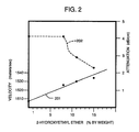
- the effects of this addition for an illustrative composition are shown in FIG. 2.
- 2-Hydroxyethlyl Ether there is insignificant change in attentuation and a small change in velocity to 1526 m/s.
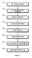
- FIG. 3 is a flow chart of a method in accordance with the present invention.
- the first step 301 is mixing 1-Butanol into Glycerol to attain velocity and impedance matched levels.
- the next step 302 is to add, as necessary, 2-Hydroxyethyl Ether to decrease attenuation to an appropriate level.
- This fluid is to be enclosed, at step 303, in the head of the ultrasonic probe.
- the window of the probe is to be pressed, at step 304, against a subject and the transducer of the probe mechanically scanned, at step 305, relative to the subject.
- Ultrasound pulses are transmitted, at step 306, from the transducer through the fluid, through the window and into the subject. At least some of the ultrasound reflections from the subject are transmitted through the window, the fluid and converted, at step 307, by the transducer to electrical signals. These electrical signals are then analyzed, at step 308, to generate an image characterizing the subject.
- the foregoing is a description of the preferred embodiments of the present invention.
- different probe dimensions and geometries are accommodated.
- a variety of transmission and receiver electronics are provided for, including both digital and analog based electronics.
- Different transducer types and geometries are provided for.
- the body supporting the transducer can have any of innumerable shapes and characteristics.
- a variety of enclosure and window types and materials are provided for.
- the drive system for steering the transducer can assume a variety of configurations.
- the coupling fluid can include other components which modify, dilute critical characteristics or which leave these characteristics unaffected but serve an ancillary function.
- Other modifications and variations are provided for by the present invention, the scope of which is limited only by the following claims.
Abstract
Description
- The present invention relates to ultrasound and, more particularly, to a system and method providing for improved coupling ultrasound between a transducer and a window of an ultrasound probe.
- Ultrasonic imaging is widely used to analyze the internal structure of organisms. For example, ultrasound is often employed to characterize the status of a fetus in a pregnant woman. Ultrasonic imaging is based on the detection of reflections of ultrasonic waves at boundaries characterized by unequal impedances. Such boundaries can represent bones, organ boundaries, changes in tissue type, etc.
- Typically, ultrasonic imaging is performed using an ultrasonic probe electrically coupled to an electronics module. The probe generally comprises a body serving as a handle, a cap or window which can pressed against the skin of a subject being imaged, and a electro-acoustic transducer enclosed by the body and window. The electronics module generates electrical pulses to be converted to ultrasonic pulses that are propagated through the window and into the subject.
- A single ultrasonic pulse can result in multiple reflections due to multiple impedance boundaries along its path of propagation. As these reflections are detected by the probe, they are converted by the transducer to an electrical signal which represents depth by time and impedance mismatches by amplitude. The electronics module analyzes this signal to recover the imaging information which can then be displayed and/or recorded as desired.
- The quality of the image obtained is largely dependent on the sensitivity with which the probe can detect reflections. A substantial portion of the energy of an ultrasonic pulse is absorbed by the probe or the body. The remaining energy is distributed among multiple reflections.
- Only a small fraction of each reflection is directed toward the probe, and much of that small fraction is absorbed before reaching the transducer. The transducer must be able to detect the occurrences and amplitude of these reflections, despite the small amounts of energy in each reflection.
- Sensitivity is a function of the aperture, or energy-gathering area, of the transducer. A transducer with a large aperture can receive a greater portion of reflected acoustic energy. On the other hand, a larger aperture implies a shallower depth of focus. A transducer is shaped and/or operated so that there is, at any given time, a single depth at which the transducer's ability to resolve depth is at a maximum. In practice, maximal resolution is not necessary, but some threshold resolution below this maximum can be required by many imaging applications. When a transducer with a small aperture is used, the range of depths for which a given threshold is met or exceeded is larger than the corresponding range of depths available when a large aperture is used.
- When the range of depths of interest is greater than the depth of field of a probe, it is necessary to obtain imaging information using focal points at successive depths. Finer steps between focal points are required for a larger aperture. Herein, the process of changing the focal length of a probe during image gathering is referred to as "zooming".
- Zooming permits high resolution imaging along a single trajectory. To obtain a two-dimensional image of a "slice" of a subject, the direction of ultrasound propagation must be panned, i.e., swept transversely or "steered". It is this steering action that gives many ultrasound images their fan-shaped form. Herein, steering and zooming are collectively referred to as "scanning".
- Scanning is performed differently by various probe types. A small aperture probe with a spherical transducer can rely on a fixed focus and mechanical steering for imaging. Theoretically, a single element transducer could be mechanically deformed to provide for zooming and, thus, larger apertures. However, annular array transducers have been developed in which time delays between concentric elements provide the zooming function; annular array transducers generally employ mechanical steering. Just as phased-arrays are used in radar, it is possible to implement a rectangular array ultrasound transducer in which all scanning is performed electronically. Such rectangular arrays involve considerable processing complexity and are not widely used. Linear phased arrays are simpler to implement and also permit electronic zooming and steering; however, elevational resolution (transverse to depth and pan) is poor.
- While each probe design has its advantages, the annular array stands out for allowing high resolution imaging in all directions while demanding less in the way of processing to generate an image from the received reflections. Zooming can be performed electronically at very high speeds for each mechanically controlled pan position.
- One challenge in designing large aperture, mechanically scanned ultrasonic transducers such as an annular array transducers is to couple ultrasound transmissions between the probe and the subject optimally. For obvious reasons, including subject comfort, the moving transducer cannot be in intimate contact with the subject. Instead, intimate contact with the subject is made by the probe window. The window material is selected to be safe, comfortable, rigid and transmissive of ultrasonic energy. A more subtle criterion is the requirement that the acoustic refractive index at ultrasound frequencies be closely matched to the subject being imaged. In other words, the acoustic velocities of window and subject should be matched. The purpose of this matching is to minimize image distortion due to changes in beam direction at the subject-window boundary.
- In addition, it is desirable to match the ultrasonic impedance of the window to the subject to minimize reflections at that surface. Such reflections bear no useful information, create reflections internal to the probe which can interfere with image clarity, and dissipate energy which could otherwise contribute to useful reflections. However, some compromise in impedance matching is tolerated to accommodate other criteria, particularly rigidity of the window.
- A fluid medium is typically interposed between a mechanically panned transducer and the associated probe window to permit steering motion while providing appropriate ultrasonic coupling between the transducer and the window and subject. The requirements for coupling include matching of transmission velocity and impedance among the fluid, window and subject for the same reasons discussed above with respect to matching the window to the body. In addition, the attenuation of the fluid must be considered to balance the requirement of efficient transmission of ultrasound and the need to damp reflections internal to the probe which could create image artifacts and otherwise degrade image quality.
- These requirements generally constrain selection of the medium material to be a liquid sealed in a chamber defined by the probe body and window. It is difficult to determine the range of coupling fluids used in mechanically scanned probes, since many of these are proprietary. Various organic liquids have been tried. Frequently, materials are mixed in an attempt to combine the characteristics of each component. However, such most combinations interact in a non-linear manner, rendering the outcome of a mixture unpredictable. While tables of attenuation and impedance are available, selection of a coupling fluid is generally a matter of trial and error.
- One problem with known coupling fluids is that it is difficult to vary one parameter of interest, e.g., impedance, without affecting another, e.g., velocity. Often, it is not possible to "tweak" a fluid mixture to obtain the desired properties. Moreover, these properties must be maintained within acceptable tolerances over a range of operating tempertures, further excluding otherwise acceptable coupling fluids.
- A number of different materials, e.g., silicone-based oils or mixtures of Glycerol with Propylene Glycol, have been successfully employed as coupling fluids for small aperture probes. However, images produced by larger aperture probes using the same fluids have been plagued by artifacts apparently due to internal reflections. What is needed is an ultrasound system and method for producing clearer images when using large aperture probes. Preferably, such a system and method would employ a coupling fluid for which one parameter of interest can be adjusted without significantly changing another parameter.
- The present invention is based on a probe design method which, rather than maximizing its transmissivity, optimizes the attenuation of the coupling fluid within a range selected to render the amplitudes of internal reflections insignificant by the time reflections of interest return to the probe transducer. The coupling fluid between the transducer and a probe window includes a mixture of 1-Butanol and Glycerol. Attenuation can be adjusted downwardly by including a suitable amount of 2-Hydroxyethyl Ether with the mixture. The invention is used to its best advantage in a mechanically scanned probe with a large aperture transducer. However, it is also applicable to other ultrasonic probes employing a coupling fluid.
- The importance of attenuation of the coupling fluid is most critical in large aperture probes. In a small aperture probe, the distance between the transducer and the window and the length of the mean free path of ultrasound, i.e., acoustic energy having a frequency of about 20 kilohertz (kHz) or greater, through the medium are both relatively short. This results in relatively many reflections per unit time. Each reflection is accompanied by some attenuation and some dissipation or loss due to transmission; reflections off the transducer are particularly attenuative. By the time a reflection of interest arrives at the transducer, a sufficient number of internal reflections occur to reduce the energy of the internal reflections to an acceptable level.
- In a large aperture probe, the mean free path is longer and there are fewer reflections per unit time. In other words, the coupling fluid in a large aperture probe serves a relatively more important role in attenuating internal reflections. For this reason, the present invention provides for a more attenuative coupling fluid than is typically employed in ultrasound probes.
- More importantly, the present invention provides for more precise control over the attenuation of the coupling fluid. Since the coupling fluid in a large aperture probe is a relatively important factor in attenuating internal reflections, it follows that performance of the incorporating ultrasound system is more sensitively affected by the extent of attenuation imposed by the coupling fluid. For this reason, it is important that the attenuation be precisely established at an optimum level.
- It is challenging to determine this optimum level. This optimum level varies in as yet difficult to predict ways on probe composition and geometry. Furthermore, for given probe, this optimum can vary according to the depths of interests and the types of tissue or other materials being explored. Therefore, coupling fluids are usually selected through a process of trial and error.
- This trial and error process can be quite tedious. In generally, adjustments to a fluid mixture to change attenuation also change velocity and/or impedance, which must be kept within predetermined bounds. Generally, fluid characteristics do not combine linearly so that it is difficult to predict the values of a mixture without testing it. Thus, a mixture which is suitable for a particular probe and application might not be modifiable for a slightly different probe or application.
- The present invention addresses this problem in a probe which includes a coupling fluid the attenuation of which can be precisely adjusted without impairing velocity and impedance matching. The preferred ratio of 1-Butanol in Glycerol provides a relatively attenuative fluid. Lower attenuations are attainable by adding 2-Hydroxyethyl Ether. Small changes in velocity and impedance can be compensated by adjusting the ratio of 1-Butanol in Glycerol slightly.
- The present invention provides for an economical and high performance ultrasound system. The economy results from the greatly reduced design time required to find an appropriate coupling fluid to achieve different attenuations. The fluid components are known as are the proportions required to attain specific levels of attenuation. This greatly relieves the amount of experimentation required to achieve optimal probe performance. Probe performance is enhanced because larger aperture probes are made more practical and because attenuation can be more closely matched to probe characteristics and to applications. These and other features and advantages are apparent from the description below with reference to the following drawings.
- FIGURE 1 is a sectional view of a probe in accordance with the present invention.
- FIGURE 2 is a graph indicating the effect on attentuation and velocity of adding 2-Hydroxyethyl Ether to a mixture of 1-Butanol in Glycerol in accordance with the present invention.
- FIGURE 3 is a flow chart depicting a method of coupling ultrasonic energy between a mechanically scanned ultrasound generator and an ultrasound window in accordance with the present invention.
- An
ultrasound system 101 includes anelectronics module 103 and aprobe 105, schematically shown in FIG. 1.Electronics module 103 includestransmitter electronics 107 andreceiver electronics 109 coupled viacable 111.Cable 111 includes lines for supplying power and ground potentials to probe 105, for delivering pulses fromtransmitter electronics 107 to probe 105, for delivering received signals fromprobe 105 toreceiver electronics 109. - A
housing 113 forprobe 105 includes aprobe head 115, a probe back 117 and aprobe handle 119.Head 115 is attached to handle 119 viahandle bracket 121. Aprobe window 123 is rigidly attached tohead 115.Window 123,head 115 and back 117 collectively define achamber 125 which is filled with acoupling fluid 127. Atransducer 131 is mounted in aspherical frame 133, which is pivotably mounted inhead 115 withbearings 129. Amotor 135 is mounted inhandle 119 by means of amotor mount 137.Motor 135 drives apinion 139 via ashaft 141. Ashaft seal 143 prevents fluid 127 from escaping intohandle 119. Drivebands 145 transfer pinion motion to provide for steering offrame 133, and thustransducer 131.Bands 145 are attached to frame 133 withbolts 147, one of two being shown. Anoptical encoder 149 provides information on pan position toreceiver electronics 109 required to construct an ultrasound image. -
Ultrasound system 101 is typical of ultrasound systems using annular phased array transducers except for modifications to incorporate the relativelarge aperture transducer 131 for increased sensitivity and the selection ofattenuative coupling fluid 127 to compensate noise problems introduced due to the increased aperture size. The aperture oftransducer 127 about three centimeters (cm), compared to a more typical 1.5 cm aperture. Couplingfluid 127 is substantially a two-component mixture consisting primarily of 1-Butanol (Butyl Alcohol) in Glycerol. This two component mixture is characterized by a velocity 1540 m/s, an impedance of 1.7 Mrayls and an attenuation of 4.1 dB/cm at 4.5 MHz. Temperature sensitivity is given by a velocity slope of -2.4 m/s/deg C and an attenuation slope of -0.1 dB/cm/deg.C). Both velocity and attenuation decrease with higher percentages of Butanol. - In an alternative embodiment of the present invention, 2-Hydroxyethyl Ether is added to the mixture to reduce attenuation. The effects of this addition for an illustrative composition are shown in FIG. 2. The starting point is a 1-Butanol/Glycerol mix at velocity = 1500 m/s, as indicated by
line 201, and attenuation = 4.1 dB/cm, as indicated byline 202. With the addition of 8% by weight of 2-Hydroxyethlyl Ether, there is insignificant change in attentuation and a small change in velocity to 1526 m/s. With an 11% by weight mixture of the 2-Hydroxyethyl Ether, attenuation drops dramatically to 2.9 dB/cm while velocity increases only slightly to 1530 m/s. With a 15% by weight mxiture, attenuation decreases to 2.3 dB/cm while velocity increases to 1534 m/s. - Looked at another way, by decreasing the percentage of 2-Hydroxyethyl Ether in the mixture from 15% to 8%, a 78% increase in attenuation can be attained while velocity decreases only half of a percent. Thus, significant attenuation control is afforded while velocity is maintain within narrow bounds. It should be noted that few fluids possess the desirable quality of allowing one to vary the attenuation without driving the velocity beyond allowable values. For purposes of comparison, changing the ratio of 1-Butanol to Glycerol to attain the same level of attenuation would result in an acceptable velocity of about 1400 m/s.
- FIG. 3 is a flow chart of a method in accordance with the present invention. The
first step 301 is mixing 1-Butanol into Glycerol to attain velocity and impedance matched levels. Thenext step 302 is to add, as necessary, 2-Hydroxyethyl Ether to decrease attenuation to an appropriate level. This fluid is to be enclosed, atstep 303, in the head of the ultrasonic probe. The window of the probe is to be pressed, atstep 304, against a subject and the transducer of the probe mechanically scanned, atstep 305, relative to the subject. Ultrasound pulses are transmitted, atstep 306, from the transducer through the fluid, through the window and into the subject. At least some of the ultrasound reflections from the subject are transmitted through the window, the fluid and converted, atstep 307, by the transducer to electrical signals. These electrical signals are then analyzed, atstep 308, to generate an image characterizing the subject. - The foregoing is a description of the preferred embodiments of the present invention. In addition, different probe dimensions and geometries are accommodated. A variety of transmission and receiver electronics are provided for, including both digital and analog based electronics. Different transducer types and geometries are provided for. The body supporting the transducer can have any of innumerable shapes and characteristics. A variety of enclosure and window types and materials are provided for. The drive system for steering the transducer can assume a variety of configurations. In addition to the components described above, the coupling fluid can include other components which modify, dilute critical characteristics or which leave these characteristics unaffected but serve an ancillary function. Other modifications and variations are provided for by the present invention, the scope of which is limited only by the following claims.
Claims (7)
Applications Claiming Priority (2)
| Application Number | Priority Date | Filing Date | Title |
|---|---|---|---|
| US24612688A | 1988-09-16 | 1988-09-16 | |
| US246126 | 1988-09-16 |
Publications (3)
| Publication Number | Publication Date |
|---|---|
| EP0359546A2 true EP0359546A2 (en) | 1990-03-21 |
| EP0359546A3 EP0359546A3 (en) | 1990-05-02 |
| EP0359546B1 EP0359546B1 (en) | 1993-08-11 |
Family
ID=22929406
Family Applications (1)
| Application Number | Title | Priority Date | Filing Date |
|---|---|---|---|
| EP19890309295 Expired - Lifetime EP0359546B1 (en) | 1988-09-16 | 1989-09-13 | Ultrasound system with improved coupling fluid |
Country Status (3)
| Country | Link |
|---|---|
| EP (1) | EP0359546B1 (en) |
| JP (1) | JPH02116356A (en) |
| DE (1) | DE68908307T2 (en) |
Cited By (4)
| Publication number | Priority date | Publication date | Assignee | Title |
|---|---|---|---|---|
| EP0589082A1 (en) * | 1992-09-24 | 1994-03-30 | Siemens Aktiengesellschaft | Intracavitary ultrasonic probe |
| EP0749722A2 (en) * | 1995-06-22 | 1996-12-27 | Hewlett-Packard Company | Handheld transthoracic rotatable ultrasound transducer |
| WO2013139849A1 (en) | 2012-03-20 | 2013-09-26 | Alstom Technology Ltd | Ultrasonic ndt sensor arrangement and method for inspecting surfaces of variable geometry of metal bodies |
| US9078593B2 (en) | 2008-02-05 | 2015-07-14 | Fujitsu Limited | Ultrasound probe device and method of operation |
Citations (4)
| Publication number | Priority date | Publication date | Assignee | Title |
|---|---|---|---|---|
| US4194510A (en) * | 1978-06-15 | 1980-03-25 | Second Foundation, Inc. | Ultrasonic focusing system |
| JPS5885694A (en) * | 1981-11-18 | 1983-05-23 | Hitachi Ltd | Sonar system |
| GB2149916A (en) * | 1983-11-16 | 1985-06-19 | Britoil Plc | Buoyant seismic streamer array |
| EP0174167A2 (en) * | 1984-08-30 | 1986-03-12 | Matsushita Electric Industrial Co., Ltd. | Ultrasonic transducers for medical diagnostic examination |
-
1989
- 1989-09-13 EP EP19890309295 patent/EP0359546B1/en not_active Expired - Lifetime
- 1989-09-13 DE DE1989608307 patent/DE68908307T2/en not_active Expired - Fee Related
- 1989-09-13 JP JP23834189A patent/JPH02116356A/en active Pending
Patent Citations (4)
| Publication number | Priority date | Publication date | Assignee | Title |
|---|---|---|---|---|
| US4194510A (en) * | 1978-06-15 | 1980-03-25 | Second Foundation, Inc. | Ultrasonic focusing system |
| JPS5885694A (en) * | 1981-11-18 | 1983-05-23 | Hitachi Ltd | Sonar system |
| GB2149916A (en) * | 1983-11-16 | 1985-06-19 | Britoil Plc | Buoyant seismic streamer array |
| EP0174167A2 (en) * | 1984-08-30 | 1986-03-12 | Matsushita Electric Industrial Co., Ltd. | Ultrasonic transducers for medical diagnostic examination |
Non-Patent Citations (2)
| Title |
|---|
| PATENT ABSTRACTS OF JAPAN, vol. 7, no. 182, 11th August 1983, page 1327; & JP-A-58 85 694 (HITACHI K.K.) 23-05-1983 * |
| ULTRASONICS, vol. 18, no. 2, March 1980, Guildford, GB; "Medical Ultrasound Scanning Couplants", page 54 * |
Cited By (7)
| Publication number | Priority date | Publication date | Assignee | Title |
|---|---|---|---|---|
| EP0589082A1 (en) * | 1992-09-24 | 1994-03-30 | Siemens Aktiengesellschaft | Intracavitary ultrasonic probe |
| US5400790A (en) * | 1992-09-24 | 1995-03-28 | Siemens Aktiengesellschaft | Intracavitary ultrasound probe |
| EP0749722A2 (en) * | 1995-06-22 | 1996-12-27 | Hewlett-Packard Company | Handheld transthoracic rotatable ultrasound transducer |
| EP0749722A3 (en) * | 1995-06-22 | 1997-04-16 | Hewlett Packard Co | Handheld transthoracic rotatable ultrasound transducer |
| US9078593B2 (en) | 2008-02-05 | 2015-07-14 | Fujitsu Limited | Ultrasound probe device and method of operation |
| WO2013139849A1 (en) | 2012-03-20 | 2013-09-26 | Alstom Technology Ltd | Ultrasonic ndt sensor arrangement and method for inspecting surfaces of variable geometry of metal bodies |
| US9945816B2 (en) | 2012-03-20 | 2018-04-17 | Ansaldo Energia Ip Uk Limited | Ultrasonic NDT sensor arrangement and method for inspecting surfaces of variable geometry of metal bodies |
Also Published As
| Publication number | Publication date |
|---|---|
| EP0359546A3 (en) | 1990-05-02 |
| DE68908307D1 (en) | 1993-09-16 |
| JPH02116356A (en) | 1990-05-01 |
| DE68908307T2 (en) | 1994-03-17 |
| EP0359546B1 (en) | 1993-08-11 |
Similar Documents
| Publication | Publication Date | Title |
|---|---|---|
| US6629929B1 (en) | Method and apparatus for automatically setting the transmit aperture and apodization of an ultrasound transducer array | |
| US4339952A (en) | Cylindrical transducer ultrasonic scanner | |
| US4455872A (en) | Rotating ultrasonic scanner | |
| US7135809B2 (en) | Ultrasound transducer | |
| US4143554A (en) | Ultrasonic scanner | |
| US5820564A (en) | Method and apparatus for surface ultrasound imaging | |
| US5678554A (en) | Ultrasound transducer for multiple focusing and method for manufacture thereof | |
| US5360007A (en) | Ultrasonic apparatus | |
| GB2027197A (en) | Ultrasonic imaging apparatus | |
| EP0320444A1 (en) | Portable ultrasonic probe | |
| US4470305A (en) | Annular array used as a horn transducer | |
| Karrer et al. | A phased array acoustic imaging system for medical use | |
| US4257271A (en) | Selectable delay system | |
| US6409669B1 (en) | Ultrasound transducer assembly incorporating acoustic mirror | |
| Foster et al. | The conical scanner: a two transducer ultrasound scatter imaging technique | |
| CN104812311A (en) | Ultrasonic probe and ultrasonic diagnostic device | |
| EP0110593B1 (en) | Ultrasonic scanning apparatus and techniques | |
| US4410826A (en) | Ultrasonic imaging apparatus using a coupling fluid mixture of propylene oxide, ethylene oxide derivative and glycerine | |
| KR102457217B1 (en) | Probe and manufacturing method thereof | |
| WO1990001171A1 (en) | Ultrasonic reflex transmission imaging method and apparatus with artifact removal | |
| Ylitalo | On the signal-to-noise ratio of a synthetic aperture ultrasound imaging method | |
| US5052393A (en) | Ultrasound system with improved coupling fluid | |
| EP0359546B1 (en) | Ultrasound system with improved coupling fluid | |
| CA1145449A (en) | Conical transducer ultrasonic scanner | |
| US4612809A (en) | Curved-array ultrasonic probe using low-velocity fluid |
Legal Events
| Date | Code | Title | Description |
|---|---|---|---|
| PUAI | Public reference made under article 153(3) epc to a published international application that has entered the european phase |
Free format text: ORIGINAL CODE: 0009012 |
|
| PUAL | Search report despatched |
Free format text: ORIGINAL CODE: 0009013 |
|
| AK | Designated contracting states |
Kind code of ref document: A2 Designated state(s): DE FR GB IT NL |
|
| AK | Designated contracting states |
Kind code of ref document: A3 Designated state(s): DE FR GB IT NL |
|
| 17P | Request for examination filed |
Effective date: 19900816 |
|
| 17Q | First examination report despatched |
Effective date: 19920325 |
|
| GRAA | (expected) grant |
Free format text: ORIGINAL CODE: 0009210 |
|
| ITF | It: translation for a ep patent filed |
Owner name: SOCIETA' ITALIANA BREVETTI S.P.A. |
|
| AK | Designated contracting states |
Kind code of ref document: B1 Designated state(s): DE FR GB IT NL |
|
| REF | Corresponds to: |
Ref document number: 68908307 Country of ref document: DE Date of ref document: 19930916 |
|
| ET | Fr: translation filed | ||
| PLBE | No opposition filed within time limit |
Free format text: ORIGINAL CODE: 0009261 |
|
| STAA | Information on the status of an ep patent application or granted ep patent |
Free format text: STATUS: NO OPPOSITION FILED WITHIN TIME LIMIT |
|
| 26N | No opposition filed | ||
| PGFP | Annual fee paid to national office [announced via postgrant information from national office to epo] |
Ref country code: FR Payment date: 19960814 Year of fee payment: 8 |
|
| PGFP | Annual fee paid to national office [announced via postgrant information from national office to epo] |
Ref country code: NL Payment date: 19960820 Year of fee payment: 8 Ref country code: DE Payment date: 19960820 Year of fee payment: 8 |
|
| PGFP | Annual fee paid to national office [announced via postgrant information from national office to epo] |
Ref country code: GB Payment date: 19960828 Year of fee payment: 8 |
|
| PG25 | Lapsed in a contracting state [announced via postgrant information from national office to epo] |
Ref country code: GB Free format text: LAPSE BECAUSE OF NON-PAYMENT OF DUE FEES Effective date: 19970913 |
|
| PG25 | Lapsed in a contracting state [announced via postgrant information from national office to epo] |
Ref country code: FR Free format text: THE PATENT HAS BEEN ANNULLED BY A DECISION OF A NATIONAL AUTHORITY Effective date: 19970930 |
|
| PG25 | Lapsed in a contracting state [announced via postgrant information from national office to epo] |
Ref country code: NL Free format text: LAPSE BECAUSE OF NON-PAYMENT OF DUE FEES Effective date: 19980401 |
|
| GBPC | Gb: european patent ceased through non-payment of renewal fee |
Effective date: 19970913 |
|
| NLV4 | Nl: lapsed or anulled due to non-payment of the annual fee |
Effective date: 19980401 |
|
| PG25 | Lapsed in a contracting state [announced via postgrant information from national office to epo] |
Ref country code: DE Free format text: LAPSE BECAUSE OF NON-PAYMENT OF DUE FEES Effective date: 19980603 |
|
| REG | Reference to a national code |
Ref country code: FR Ref legal event code: ST |
|
| PG25 | Lapsed in a contracting state [announced via postgrant information from national office to epo] |
Ref country code: IT Free format text: LAPSE BECAUSE OF NON-PAYMENT OF DUE FEES Effective date: 20050913 |