EP0434503A1 - Coherent pulse radar system and method for detecting a target presenting flashes of a very short duration - Google Patents
Coherent pulse radar system and method for detecting a target presenting flashes of a very short duration Download PDFInfo
- Publication number
- EP0434503A1 EP0434503A1 EP90403543A EP90403543A EP0434503A1 EP 0434503 A1 EP0434503 A1 EP 0434503A1 EP 90403543 A EP90403543 A EP 90403543A EP 90403543 A EP90403543 A EP 90403543A EP 0434503 A1 EP0434503 A1 EP 0434503A1
- Authority
- EP
- European Patent Office
- Prior art keywords
- thresholds
- maximum amplitude
- pulses
- channels
- rank
- Prior art date
- Legal status (The legal status is an assumption and is not a legal conclusion. Google has not performed a legal analysis and makes no representation as to the accuracy of the status listed.)
- Withdrawn
Links
Images


Classifications
-
- G—PHYSICS
- G01—MEASURING; TESTING
- G01S—RADIO DIRECTION-FINDING; RADIO NAVIGATION; DETERMINING DISTANCE OR VELOCITY BY USE OF RADIO WAVES; LOCATING OR PRESENCE-DETECTING BY USE OF THE REFLECTION OR RERADIATION OF RADIO WAVES; ANALOGOUS ARRANGEMENTS USING OTHER WAVES
- G01S13/00—Systems using the reflection or reradiation of radio waves, e.g. radar systems; Analogous systems using reflection or reradiation of waves whose nature or wavelength is irrelevant or unspecified
- G01S13/02—Systems using reflection of radio waves, e.g. primary radar systems; Analogous systems
- G01S13/06—Systems determining position data of a target
- G01S13/08—Systems for measuring distance only
- G01S13/10—Systems for measuring distance only using transmission of interrupted, pulse modulated waves
- G01S13/26—Systems for measuring distance only using transmission of interrupted, pulse modulated waves wherein the transmitted pulses use a frequency- or phase-modulated carrier wave
- G01S13/28—Systems for measuring distance only using transmission of interrupted, pulse modulated waves wherein the transmitted pulses use a frequency- or phase-modulated carrier wave with time compression of received pulses
- G01S13/284—Systems for measuring distance only using transmission of interrupted, pulse modulated waves wherein the transmitted pulses use a frequency- or phase-modulated carrier wave with time compression of received pulses using coded pulses
- G01S13/288—Systems for measuring distance only using transmission of interrupted, pulse modulated waves wherein the transmitted pulses use a frequency- or phase-modulated carrier wave with time compression of received pulses using coded pulses phase modulated
-
- G—PHYSICS
- G01—MEASURING; TESTING
- G01S—RADIO DIRECTION-FINDING; RADIO NAVIGATION; DETERMINING DISTANCE OR VELOCITY BY USE OF RADIO WAVES; LOCATING OR PRESENCE-DETECTING BY USE OF THE REFLECTION OR RERADIATION OF RADIO WAVES; ANALOGOUS ARRANGEMENTS USING OTHER WAVES
- G01S13/00—Systems using the reflection or reradiation of radio waves, e.g. radar systems; Analogous systems using reflection or reradiation of waves whose nature or wavelength is irrelevant or unspecified
- G01S13/02—Systems using reflection of radio waves, e.g. primary radar systems; Analogous systems
- G01S13/06—Systems determining position data of a target
- G01S13/08—Systems for measuring distance only
- G01S13/10—Systems for measuring distance only using transmission of interrupted, pulse modulated waves
- G01S13/22—Systems for measuring distance only using transmission of interrupted, pulse modulated waves using irregular pulse repetition frequency
- G01S13/225—Systems for measuring distance only using transmission of interrupted, pulse modulated waves using irregular pulse repetition frequency with cyclic repetition of a non-uniform pulse sequence, e.g. staggered PRF
-
- G—PHYSICS
- G01—MEASURING; TESTING
- G01S—RADIO DIRECTION-FINDING; RADIO NAVIGATION; DETERMINING DISTANCE OR VELOCITY BY USE OF RADIO WAVES; LOCATING OR PRESENCE-DETECTING BY USE OF THE REFLECTION OR RERADIATION OF RADIO WAVES; ANALOGOUS ARRANGEMENTS USING OTHER WAVES
- G01S13/00—Systems using the reflection or reradiation of radio waves, e.g. radar systems; Analogous systems using reflection or reradiation of waves whose nature or wavelength is irrelevant or unspecified
- G01S13/02—Systems using reflection of radio waves, e.g. primary radar systems; Analogous systems
- G01S13/06—Systems determining position data of a target
- G01S13/08—Systems for measuring distance only
- G01S13/10—Systems for measuring distance only using transmission of interrupted, pulse modulated waves
- G01S13/30—Systems for measuring distance only using transmission of interrupted, pulse modulated waves using more than one pulse per radar period
-
- G—PHYSICS
- G01—MEASURING; TESTING
- G01S—RADIO DIRECTION-FINDING; RADIO NAVIGATION; DETERMINING DISTANCE OR VELOCITY BY USE OF RADIO WAVES; LOCATING OR PRESENCE-DETECTING BY USE OF THE REFLECTION OR RERADIATION OF RADIO WAVES; ANALOGOUS ARRANGEMENTS USING OTHER WAVES
- G01S13/00—Systems using the reflection or reradiation of radio waves, e.g. radar systems; Analogous systems using reflection or reradiation of waves whose nature or wavelength is irrelevant or unspecified
- G01S13/02—Systems using reflection of radio waves, e.g. primary radar systems; Analogous systems
- G01S13/50—Systems of measurement based on relative movement of target
- G01S13/52—Discriminating between fixed and moving objects or between objects moving at different speeds
- G01S13/522—Discriminating between fixed and moving objects or between objects moving at different speeds using transmissions of interrupted pulse modulated waves
- G01S13/524—Discriminating between fixed and moving objects or between objects moving at different speeds using transmissions of interrupted pulse modulated waves based upon the phase or frequency shift resulting from movement of objects, with reference to the transmitted signals, e.g. coherent MTi
- G01S13/5246—Discriminating between fixed and moving objects or between objects moving at different speeds using transmissions of interrupted pulse modulated waves based upon the phase or frequency shift resulting from movement of objects, with reference to the transmitted signals, e.g. coherent MTi post processors for coherent MTI discriminators, e.g. residue cancellers, CFAR after Doppler filters
Definitions
- the present invention relates to a method and a coherent radar system with unambiguous pulses of distance for the detection of a target exhibiting lightnings of very short duration and of long period, in particular helicopters.
- Certain surveillance radars seek in particular to detect targets in agitation whose radar equivalent surface may be only large enough to be detectable only for moments of very short duration. This may be the case, for example, for helicopters that one wishes to recognize as such. Indeed, we know that an essential characteristic of helicopters, from the point of view of the radar equivalent surface, is that the blades of their main rotor provide a very significant equivalent surface only when they are in the vicinity of a perpendicular plane. to the radar-helicopter direction. This configuration is repeated periodically with a period of high value, for example of the order of twenty to one hundred milliseconds, but lasts only a very short time, giving rise for example to a "flash" of a duration of the order of 50 to 200 microseconds.
- a first solution envisaged is to use pulses with a high repetition frequency and, to resolve ambiguities in distance, successively emit bursts of pulses with different repetition periods.
- a disadvantage of this solution is that it greatly increases the time required to observe the target, which makes it almost impossible to track the target.
- a solution derived from this would consist in using interlaced bursts at low frequency of constant repetition (therefore unambiguously distance for the radar coverage envisaged), each burst using a different carrier frequency.
- this solution like the previous one, requires N transmitters and N receivers with different carrier frequencies, which implies complex, bulky and expensive equipment.
- the invention aims to remedy these drawbacks by starting from the observation that the blade flashes are rare in time and in distance because there are generally few helicopters in the field of radar surveillance. This means that partial ambiguities can be tolerated from a distance.
- the pulses of a periodic pattern will be differentiated by applying to them different phase modulations and preferably pseudo-orthogonal (with low intercorrelation) modulations, the modulation being coherent. for all of the pulses.
- One of the advantages of such a method is that a single transmitter and receiver can be used, the receiver being followed by N sub-receivers or signal processing channels corresponding to the various pulses.
- these pulses are separated by durations T1, T2 ... all different but close to the period Tm of the pattern divided by N.
- This average period Tm / N is chosen to be of the order of magnitude of the minimum duration of the flashes to detect.
- the period Tm of the pattern is chosen so that it corresponds to an ambiguity in distance greater than the distance coverage sought.
- Modulation laws are chosen in pseudo-orthogonal phase, that is to say having low values of intercorrelation function. This is important for the proper functioning of the system as will be seen below.
- a radar system using this principle according to the invention comprises only one transmitter, transmitting successive pulses at the same carrier frequency but with adequate phase modulation, and a single receiver followed by N signal processing channels each corresponding to a particular pulse compression channel, that is to say a pulse of the pattern.
- the filtering for elimination of parasitic echoes is carried out from pattern to pattern and therefore has the same efficiency as in an unambiguous radar of distance with periodic pulses.
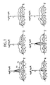
- the radar system according to the invention presents partial ambiguities in distance. Indeed, as the phase modulation laws are not perfectly orthogonal (intercorrelation products not equal to zero), a blade flash echo corresponding to a particular pulse will give a main peak in the corresponding channel but also non-zero secondary peaks in other routes.
- FIG. 3 This is shown diagrammatically in FIG. 3 where is represented in A the ambiguity diagram of a sub-receptor (or processing channel) alone with its main peaks and in B the ambiguity diagram of a sub-receiver in the presence on the other, for example those corresponding to pulses 11 and 12.
- A the ambiguity diagram of a sub-receptor (or processing channel) alone with its main peaks
- B the ambiguity diagram of a sub-receiver in the presence on the other, for example those corresponding to pulses 11 and 12.
- We are then in the presence of secondary peaks spaced from T1 of the main peaks which correspond to partial ambiguities in distance.
- the secondary peaks are of sufficiently low amplitude to be eliminated by comparison of the amplitudes received at each instant in the various processing channels, as will be seen below. below.
- Diagram A represents what happens to the radar system during the emission of a pulse. All the processing channels are obscured not only during the duration Te of the transmitted pulse, for example 11, but also for a time. Taem of pre-emission and a time Tpe of post-emission. The reception time is therefore Trc.
- FIG. 5 shows the time diagram of a three-pulse pattern I1, I2, 13 (three pulses only for clarity of the figures).
- the duration of the pattern is Tm.
- Each pulse is separated from the next by a different spacing, respectively T1, T2 and T3.
- Each pulse defines an area of unobservability represented by hatching.
- Tq the duration of such a domain and we choose Tq as the time quantization step
- Ti the durations Ti (i equal to 1, 2 or 3) by numbers. If these numbers are suitably chosen, it can be seen from diagram B in FIG. 4 that it can be achieved that none of the domains of non-observability of each of the channels overlaps, except at the start of each pattern which is inevitable.
- Diagram C consequently represents the rate of observability of the distances D.
- the minimum rate of observability can be adjusted.
- FIG. 6 represents the diagram of a radar system implementing the principles mentioned above.
- the radar system comprises a common transmit-receive antenna 1 connected to a circulator 2.
- the transmitter connected to this circulator consists of an oscillator 3 at the carrier frequency F a , a phase modulator 4 and an amplifier 5.
- the wave supplied by the oscillator 3 is modulated in pulses and, inside each pulse, in phase under the control of a sequencer 6 which synchronizes the pulses and provides the appropriate modulation laws (codes).
- the circulator2 is also connected to unique reception means comprising the receiver 7 and the device 8 for the coherent elimination of clutter echoes and of the target body echo by linear filtering.
- a device can for example be a filter with autoregressive signal processing.
- This filter comprises in known manner a lattice filter of order 1 and a coefficient calculator a n-1 of the lattice filter.
- the calculation of the filtering coefficient can be carried out recursively from the coefficient of the previous recurrence and from an estimate of the coefficient at the recurrence considered.
- the trellis filter provides, for each resolution cell, direct pn and retrograde signals r n according to the relationships: where y n is the input signal of the recurrence n and the symbol * means "conjugate of".
- This output signal is applied in parallel to N processing channels each corresponding to a particular pulse of the pattern, that is to say to a particular pulse compression from the corresponding phase modulation law.
- Each processing channel includes a device 9.1 to 9.N for pulse compression (CI1 to CIN), which receives from the sequencer 6 the replica of the phase modulation law used at transmission to correlate with the received signal. , and a threshold circuit 10.1 to 10.N intended to eliminate noise. The amplitudes in digital form supplied to these threshold circuits are set to zero if they are below the noise threshold.
- the outputs of the N channels are applied to a device 11 for eliminating secondary peaks due to partial ambiguities.
- This device is intended to retain only the signals corresponding to an effective detection of blade flash, that is to say the main peaks. These main peaks detected are sent to display means not shown.
- FIG. 7 makes it possible to better understand the principles on which the operation of the device 11 is based. Still assuming to simplify that there are only three paths, the diagrams of the first line of FIG. 7 represent, in the case of a main peak in channel 1 (blade flash echo for pulse 11), the amplitude A 11 (R) of the compressed signal in channel 1 corresponding to the autocorrelation function for the pulse modulation law 11, R being the delay, and the amplitudes A 1j (R) in the channels 2 and 3 corresponding to the functions of intercorrelation of the modulation law of 11 with the corresponding laws in channels 2 and 3, which translate the signal received in channels 2 and 3 for a flash detected in channel 1.
- the diagrams of the first line of FIG. 7 represent, in the case of a main peak in channel 1 (blade flash echo for pulse 11), the amplitude A 11 (R) of the compressed signal in channel 1 corresponding to the autocorrelation function for the pulse modulation law 11, R being the delay, and the amplitudes A 1j (R) in the
- the amplitudes A1, A2, A3 present at the output of each of the processing channels at each elementary time are first applied to validation P gates 101 to 103 controlled by the observability times of each sequence of pulses 11, 12 or 13 (see Figure 5). During the observability times, the amplitudes are transmitted without modification and, during the non-observability times, the P gates transmit a zero value. After passing through gates 101 to 103, the amplitudes are applied to circuits of the shift register type comprising L + 1 registers 111, 121 ... 151 for channel 1, 113, 123 ... 153 for channel 2, etc ..., where L is the number of moments of each modulation law, the progression in these registers taking place at the rate of elementary times.
- the amplitudes of the three channels are applied to a maximum detector circuit 104 which supplies on its output the rank i of the channel having the maximum amplitude at the instant considered. These amplitudes are also applied to a circuit 105 for calculating so-called simultaneous thresholds which provides, in response to the rank and the value of the maximum amplitude of the thresholds S Ij (O) corresponding to the coefficients at time 0 of one of the three possible configurations ( Figure 5) depending on the channel with a maximum. These thresholds are compared to the amplitudes A 1 in the respective comparators S 108 to 110 to provide a detection bit D equal to 1 if the threshold is equal to or less than the corresponding amplitude and to 0 if the threshold is greater.
- This bit is then transmitted to the next stage via a register R '112, 114, 116. All the other stages are then identical and each include a comparison circuit S' (for example 118 to 120 for l 'stage 1) followed by a register R' (for example 122, 124, 126 for stage 1).
- a comparison circuit S' for example 118 to 120 for l 'stage 1
- a register R' for example 122, 124, 126 for stage 1).
- a comparison circuit comprises, as shown in FIG. 9, two comparators Ca, Cp, receiving the amplitude A of the corresponding channel delayed by one to L elementary time depending on the stage considered and a respective threshold called anterior Sa or posterior S d , and an "AND" gate AG receiving the outputs of the comparators Ca and Cp and the detection bit D of the previous stage and supplying the new detection bit D '.
- Bit D ' is worth 1 if bit D is worth 1 and if the amplitude A is greater than the two thresholds Sa and Sp. Otherwise, it takes the value 0.
- the prior thresholds, for delays R from -1 to -L, are provided by an anterior threshold generator 107 while the posterior thresholds, for delays R from +1 to + L, are provided by a posterior threshold generator 106 .
- the previous thresholds are developed from the amplitudes at the input of the device and from the rank of the channel containing the maximum amplitude.
- the posterior thresholds are developed from the amplitudes appearing at the output of the device as well as from the rank of the channel containing at output the maximum amplitude. This rank is obtained by providing a parallel progression path for rank i supplied by circuit 104 through L + 1 registers R "117, 127 ... 157.
- Generators 106 and 107 are of strictly identical structure.
- circuit 105 selection circuit, read-only memory and multipliers
- the operation of the device of FIG. 8 thus appears clearly.
- the amplitudes appearing at the input of the device are used to calculate the previous thresholds which are compared to the corresponding previous amplitudes which are present in the various stages of the device, which makes it possible to cancel the secon peak amplitude detection bits detected, when the maximum amplitude at the input becomes higher.
- the amplitudes appearing at the output of the device are used to calculate the posterior thresholds which are compared with the corresponding amplitudes arrived later and which are present in the various stages of the device which makes it possible to cancel the bits for detecting peak amplitudes secondary detected, when the maximum amplitude at the output is significantly higher.
Abstract
Description
La présente invention se rapporte à un procédé et un système radar cohérent à impulsions sans ambiguïté de distance pour la détection d'une cible présentant des éclairs de très courte durée et de période élevée, notamment des hélicoptères.The present invention relates to a method and a coherent radar system with unambiguous pulses of distance for the detection of a target exhibiting lightnings of very short duration and of long period, in particular helicopters.
Certains radars de surveillance cherchent particulièrement à détecter des cibles en agitation dont la surface équivalente radar peut n'être suffisamment forte pour être détectable que pendant des moments de très courte durée. Cela peut être le cas par exemple pour des hélicoptères que l'on veut reconnaître en tant que tels. En effet, on sait qu'une caractéristique essentielle des hélicoptères, du point de vue de la surface équivalente radar, est que les pales de leur rotor principal fournissent une surface équivalente très importante seulement lorsqu'elles sont dans le voisinage d'un plan perpendiculaire à la direction radar- hélicoptère. Cette configuration se répète périodiquement avec une période de valeur élevée, par exemple de l'ordre d'une vingtaine à une centaine de millisecondes, mais ne dure qu'un temps très court, donnant lieu par exemple à un "éclair" d'une durée de l'ordre de 50 à 200 microsecondes.Certain surveillance radars seek in particular to detect targets in agitation whose radar equivalent surface may be only large enough to be detectable only for moments of very short duration. This may be the case, for example, for helicopters that one wishes to recognize as such. Indeed, we know that an essential characteristic of helicopters, from the point of view of the radar equivalent surface, is that the blades of their main rotor provide a very significant equivalent surface only when they are in the vicinity of a perpendicular plane. to the radar-helicopter direction. This configuration is repeated periodically with a period of high value, for example of the order of twenty to one hundred milliseconds, but lasts only a very short time, giving rise for example to a "flash" of a duration of the order of 50 to 200 microseconds.
Pour qu'un radar du type à impulsions ait une probabilité suffisante de détecter ces pales, il faut choisir un espacement entre impulsions du même ordre de grandeur que la durée des éclairs de pale. Si on utilise un radar à impulsions périodiques, ce qui est nécessaire pour pouvoir éliminer convenablement les échos parasites, on doit alors utiliser des périodes de répétition conduisant à des distances maximum non ambiguës de l'ordre d'une vingtaine de kilomètres, donc trop faibles dans de nombreux cas pour la couverture en distance recherchée.For a pulse type radar to have a sufficient probability of detecting these blades, it is necessary to choose a spacing between pulses of the same order of magnitude as the duration of the blade flashes. If a periodic pulse radar is used, which is necessary in order to be able to properly eliminate parasitic echoes, then repetition periods must be used leading to unambiguous maximum distances of the order of about twenty kilometers, therefore too small in many cases for the distance coverage sought.
Une première solution envisagée est d'utiliser des impulsions à fréquence de répétition élevée et, pour lever les ambiguïtés en distance, d'émettre successivement des rafales d'impulsions à périodes de répétition différentes. Un inconvénient de cette solution est qu'on augmente beaucoup le temps d'observation de la cible nécessaire, d'où une quasi-impossibilité de réaliser un pistage de la cible.A first solution envisaged is to use pulses with a high repetition frequency and, to resolve ambiguities in distance, successively emit bursts of pulses with different repetition periods. A disadvantage of this solution is that it greatly increases the time required to observe the target, which makes it almost impossible to track the target.
Une autre solution connue, décrite par exemple dans le brevet français N° 77 38830, consiste à utiliser des blocs d'impulsions à fréquence de répétition constante différente d'un bloc à l'autre ces blocs étant entrelacés et les impulsions d'un bloc étant reconnues parleur fréquence porteuse, différente d'un bloc à l'autre. Mais dans ce cas aussi, pour lever l'ambiguïté en distance, le temps d'observation est long.Another known solution, described for example in French patent No. 77 38830, consists in using blocks of pulses with a constant repetition frequency different from one block to another, these blocks being interleaved and the pulses of a block being recognized by carrier frequency, different from one block to another. But in this case too, to remove the ambiguity in distance, the observation time is long.
Une solution dérivée de celle-ci consisterait à utiliser des rafales entrelacées à basse fréquence de répétition constante (donc sans ambiguïté distance pour la couverture radar envisagée), chaque rafale utilisant une fréquence porteuse différente. Cependant cette solution, tout comme la précédente, nécessite N émetteurs et N récepteurs à fréquence porteuse différente, ce qui implique un matériel complexe, encombrant et coûteux.A solution derived from this would consist in using interlaced bursts at low frequency of constant repetition (therefore unambiguously distance for the radar coverage envisaged), each burst using a different carrier frequency. However, this solution, like the previous one, requires N transmitters and N receivers with different carrier frequencies, which implies complex, bulky and expensive equipment.
L'invention a pour but de remédier à ces inconvénients en partant de la constatation que les éclairs de pale sont rares dans le temps et en distance car il y a généralement peu d'hélicoptères dans le domaine de surveillance d'un radar. Ceci entraîne qu'on peut tolérer des ambiguités partielles en distance.The invention aims to remedy these drawbacks by starting from the observation that the blade flashes are rare in time and in distance because there are generally few helicopters in the field of radar surveillance. This means that partial ambiguities can be tolerated from a distance.
Conformément à l'invention, au lieu d'utiliser des fréquences porteuses différentes, on va différencier les impulsions d'un motif périodique en leur appliquant des modulations de phase différentes et de préférence pseudo-orthogonales (à intercorrélation faible), la modulation étant cohérente pour l'ensemble des impulsions.According to the invention, instead of using different carrier frequencies, the pulses of a periodic pattern will be differentiated by applying to them different phase modulations and preferably pseudo-orthogonal (with low intercorrelation) modulations, the modulation being coherent. for all of the pulses.
Selon l'invention, il est donc prévu un procédé pour la détection sans ambiguité de distance, par un radar cohérent à impulsions, d'une cible présentant des éclairs de très courte durée et de période élevée, notamment des hélicoptères, caractérisé en ce qu'il consiste à :
- - émettre périodiquement un motif de N impulsions ayant toutes la même fréquence porteuse, cohérentes entre elles et modulées chacune en phase par une loi différente, lesdites impulsions d'un motif étant espacées entre elles de durées toutes différentes, voisines de la période du motif divisée par N et du même ordre de grandeur que la durée desdits éclairs ;
- - recevoir lesdites impulsions par un récepteur unique suivi de N voies de traitement adaptées respectivement auxdites lois de modulation pour effectuer une compression d'impulsion ; et
- - éliminer les pics secondaires reçus par comparaison des niveaux reçus dans chacune des voies.
- - periodically transmit a pattern of N pulses all having the same carrier frequency, mutually consistent and each modulated in phase by a different law, said pulses of a pattern being spaced apart from one another of all different durations, close to the period of the divided pattern by N and of the same order of magnitude as the duration of said flashes;
- - receiving said pulses by a single receiver followed by N processing channels adapted respectively to said modulation laws to perform pulse compression; and
- - eliminate the secondary peaks received by comparing the levels received in each of the channels.
Un des avantages d'un tel procédé est qu'on peut utiliser un émetteur et un récepteur uniques, le récepteur étant suivi de N sous-récepteurs ou voies de traitement des signaux correspondant aux diverses impulsions.One of the advantages of such a method is that a single transmitter and receiver can be used, the receiver being followed by N sub-receivers or signal processing channels corresponding to the various pulses.
L'invention sera mieux comprise et d'autres caractéristiques et avantages apparaîtront à l'aide de la description ci-après et des dessins joints où :
- - la figure 1 représente des diagrammes explicatifs ;
- - la figure 2 montre le diagramme des impulsions émises selon l'invention ;
- - la figure 3 représente des diagrammes d'ambiguïté explicatifs de l'invention ;
- - la figure 4 représente une série de courbes définissant les paramètres jouant sur le temps d'observabilité du radar selon l'invention ;
- - la figure 5 montre des courbes explicatives du choix des espacements d'impulsions selon l'invention ;
- - la figure 6 est le schéma de principe d'un système radar selon l'invention ;
- - la figure 7 représente des diagrammes explicitant le principe d'élimination des pics secondaires selon l'invention ;
- - la figure 8 est le schéma d'un dispositif d'élimination des pics secondaires utilisable dans le système selon l'invention ;
- - la figure 9 est le détail d'un circuit du dispositif de la figure 8 ; et
- - la figure 10 est le schéma détaillé d'un dispositif de calcul de seuil utilisé dans le dispositif de la figure 8.
- - Figure 1 shows explanatory diagrams;
- - Figure 2 shows the diagram of the pulses transmitted according to the invention;
- - Figure 3 shows explanatory ambiguity diagrams of the invention;
- - Figure 4 represents a series of challenge curves defining the parameters playing on the observability time of the radar according to the invention;
- - Figure 5 shows explanatory curves for the choice of pulse spacings according to the invention;
- - Figure 6 is the block diagram of a radar system according to the invention;
- - Figure 7 shows diagrams explaining the principle of elimination of secondary peaks according to the invention;
- - Figure 8 is the diagram of a device for eliminating secondary peaks usable in the system according to the invention;
- - Figure 9 is the detail of a circuit of the device of Figure 8; and
- FIG. 10 is the detailed diagram of a threshold calculation device used in the device of FIG. 8.
Comme on l'a déjà expliqué dans l'introduction de la présente description, si, dans un radar à impulsions périodiques, l'espacement entre impulsions 11, 12, 13 est trop important par rapport à la durée d'un éclair de pale EP (courbe A de la figure 1), on risque de ne pas détecter cet éclair si aucune impulsion n'est présente au moment où la surface équivalente radar de la pale est élevée. Une des solutions possibles à ce problème consiste à émettre des rafales d'impulsions RF1, RF2 ... à fréquence de répétition différente et élevée (diagramme B de la figure 1), ce qui entraîne, comme on l'a indiqué, un temps d'observation trop long pour certaines applications.As already explained in the introduction to the present description, if, in a radar with periodic pulses, the spacing between
Selon l'invention et comme schématisé sur la figure 2, on émet un motif périodique de N impulsions 11, 12, 13 (pour simplifier les figures on a choisi N=3) ayant toutes la même fréquence porteuse, cohérentes entre elles, mais chacune modulée en phase par une loi différente. De plus, ces impulsions sont séparées par des durées T1, T2 ... toutes différentes mais voisines de la période Tm du motif divisée par N. Cette période moyenne Tm/N est choisie de l'ordre de grandeur de la durée minimum des éclairs à détecter. La période Tm du motif est choisie de telle sorte qu'elle corresponde à une ambigutté en distance supérieure à la couverture en distance recherchée.According to the invention and as shown diagrammatically in FIG. 2, a periodic pattern of
On choisit des lois de modulation en phase pseudo-orthogonales, c'est-à-dire ayant de faibles valeurs de fonction d'intercorrélation. Ceci est important pour un bon fonctionnement du système ainsi qu'on le verra ci-dessous.Modulation laws are chosen in pseudo-orthogonal phase, that is to say having low values of intercorrelation function. This is important for the proper functioning of the system as will be seen below.
Un système radar utilisant ce principe selon l'invention ne comporte qu'un seul émetteur, émettant les impulsions successives à la même fréquence porteuse mais avec une modulation de phase adéquate, et un seul récepteur suivi de N voies de traitement du signal correspondant chacune à une voie de compression d'impulsion particulière, c'est-à-dire à une impulsion du motif.A radar system using this principle according to the invention comprises only one transmitter, transmitting successive pulses at the same carrier frequency but with adequate phase modulation, and a single receiver followed by N signal processing channels each corresponding to a particular pulse compression channel, that is to say a pulse of the pattern.
Le filtrage d'élimination des échos parasites s'effectue de motif à motif et a donc la même efficacité que dans un radar sans ambiguïté de distance à impulsions périodiques.The filtering for elimination of parasitic echoes is carried out from pattern to pattern and therefore has the same efficiency as in an unambiguous radar of distance with periodic pulses.
Cependant le système radar selon l'invention présente des ambiguïtés partielles en distance. En effet, comme les lois de modulation de phase ne sont pas parfaitement orthogonales (produits d'intercorrélation non égaux à zéro), un écho d'éclair de pale correspondant à une impulsion particulière va donner un pic principal dans la voie correspondante mais aussi des pics secondaires non nuls dans les autres voies.However, the radar system according to the invention presents partial ambiguities in distance. Indeed, as the phase modulation laws are not perfectly orthogonal (intercorrelation products not equal to zero), a blade flash echo corresponding to a particular pulse will give a main peak in the corresponding channel but also non-zero secondary peaks in other routes.
Ceci est schématisé sur la figure 3 où est représenté en A le diagramme d'ambiguïté d'un sous-récepteur (ou voie de traitement) seul avec ses pics principaux et en B le diagramme d'ambiguïté d'un sous-récepteur en présence d'un autre, par exemple ceux correspondant aux impulsions 11 et 12. On se trouve alors en présence de pics secondaires espacés de T1 des pics principaux qui correspondent à des ambiguïtés partielles en distance. Cependant, compte tenu des caractéristiques de pseudo-orthogonalité choisies pour les lois de modulation, les pics secondaires sont d'amplitude suffisamment faible pour être éliminés par comparaison des amplitudes reçues à chaque instant dans les diverses voies de traitement, comme on le verra ci-dessous.This is shown diagrammatically in FIG. 3 where is represented in A the ambiguity diagram of a sub-receptor (or processing channel) alone with its main peaks and in B the ambiguity diagram of a sub-receiver in the presence on the other, for example those corresponding to
Un autre problème qui se pose est dû au fait que pendant l'émission de chaque impulsion par l'émetteur, toutes les voies de traitement sont occultées. Si on veut éviter d'avoir une zone en distance complètement aveugle, il faut donc éviter d'avoir un espacement constant entre impulsions successives. Par contre on peut parfaitement tolérer que, pour toute distance donnée, une ou quelques voies de traitement soient aveugles si les autres ne le sont pas. Ceci amène à définir des lois possibles de répartition des espacements entre impulsions successives qui répondent aux impératifs ci-dessus.Another problem which arises is due to the fact that during the emission of each pulse by the transmitter, all the processing channels are obscured. If we want to avoid having a completely blind distance zone, we must therefore avoid having a constant spacing between successive pulses. On the other hand, it is perfectly tolerable that, for any given distance, one or a few treatment paths are blind if the others are not. This leads to defining possible laws of distribution of the spacings between successive pulses which meet the above requirements.
On va maintenant définir à titre d'exemple une loi de répartition de ces espacements qui est simple à mettre en oeuvre et efficace.We will now define by way of example a distribution law for these spacings which is simple to implement and effective.
Pour cela, on va d'abord définir en relation avec la figure 4 un certain nombre de paramètres importants.For this, we will first define in relation to Figure 4 a number of important parameters.
Le diagramme A représente ce qui se passe pour le système radar lors de l'émission d'une impulsion.Toutes les voies de traitement sont occultées non seulement pendant la durée Te de l'impulsion émise, par exemple 11, mais aussi pendant un temps Tae de préémission etun temps Tpe de postémission. Le temps de réception est donc Trc.Diagram A represents what happens to the radar system during the emission of a pulse. All the processing channels are obscured not only during the duration Te of the transmitted pulse, for example 11, but also for a time. Taem of pre-emission and a time Tpe of post-emission. The reception time is therefore Trc.
De même, dans chaque sous-récepteur ou voie de traitement, la corrélation avec la loi de modulation s'effectue pour un retard R correspondant à une distance D = c.Rl2 (c vitesse de l'onde électro-magnétique) sur une durée Tc égale à Te qui doit être précédée d'un temps de précorrélation Tac et suivie d'un temps de postcorrélation Tpc (diagramme B de la figure 4).Similarly, in each sub-receiver or processing channel, the correlation with the modulation law is carried out for a delay R corresponding to a distance D = c.Rl2 (c speed of the electromagnetic wave) over a period Tc equal to Te which must be preceded by a precorrelation time Tac and followed a postcorrelation time Tpc (diagram B in FIG. 4).
Le diagramme C permet alors de définir le champ d'observabilité du système radar pour la vole considérée. Une corrélation ne peut être effectuée correctement et une cible détectée qu'entre une distance minimum Dmin = c.Rmin/2 où Rmin = Te + Tpe + Tac (point F) et une distance maximum Dmax = c.Rmaxl2 limitée au point G précédant le début de l'impulsion suivante d'un délai égal à Tc + Tpc + Tae. On définit ainsi pour chaque impulsion un domaine d'inobserva- bilité de durée Tc + Tpc + Tae + Te + Tpe + Tac.Diagram C then makes it possible to define the field of observability of the radar system for the flight considered. Correlation can only be performed correctly and a target detected between a minimum distance Dmin = c.Rmin / 2 where Rmin = Te + Tpe + Tac (point F) and a maximum distance Dmax = c.Rmaxl2 limited to the previous point G the start of the next pulse with a delay equal to Tc + Tpc + Tae. Thus, for each pulse, a domain of unobservability of duration Tc + Tpc + Tae + Te + Tpe + Tac is defined.
Cela étant, on a représenté sur la figure 5, le diagramme de temps d'un motif à trois impulsions I1,I2, 13 (trois impulsions seulement pour la clarté des figures). La durée du motif est Tm. Chaque impulsion est séparée de la suivante par un espacement différent, respectivement T1, T2 et T3. Chaque impulsion définit un domaine d'inobservabilité représenté par des hachures. Si on appelle Tq la durée d'un tel domaine et qu'on choisit Tq comme pas de quantification des temps, on exprime les durées Ti (i égal à 1, 2 ou 3) par des nombres. Si ces nombres sont convenablement choisis, on voit d'après le diagramme B de la figure 4 qu'on peut arriver à ce qu'aucun des domaines d'inobservabilité de chacune des voies ne se chevauche, excepté au début de chaque motif ce qui est inévitable. Pour obtenir ce résultat, il suffit de choisir les espacements tels que tous les nombres Ti, Ti + Ti⊕31, Ti + Ti⊕1 + Ti⊕2 ..., Ti + Ti⊕1 + ... + Ti⊕Nθ2 soient différents, les symboles ⊕ et 9 représentant des additions et des soustractions modulo N. Sur le diagramme B, les zones hachurées ln 11, In 12, ln 13 représentent les domaines d'inobservabilité par la suite d'impulsions 11 de la voie 1, etc ...However, FIG. 5 shows the time diagram of a three-pulse pattern I1, I2, 13 (three pulses only for clarity of the figures). The duration of the pattern is Tm. Each pulse is separated from the next by a different spacing, respectively T1, T2 and T3. Each pulse defines an area of unobservability represented by hatching. If we call Tq the duration of such a domain and we choose Tq as the time quantization step, we express the durations Ti (i equal to 1, 2 or 3) by numbers. If these numbers are suitably chosen, it can be seen from diagram B in FIG. 4 that it can be achieved that none of the domains of non-observability of each of the channels overlaps, except at the start of each pattern which is inevitable. To obtain this result, it suffices to choose the spacings such that all the numbers Ti, Ti + Ti⊕31, Ti + Ti⊕1 + Ti⊕2 ..., Ti + Ti⊕1 + ... + Ti⊕Nθ2 are different, the symbols ⊕ and 9 representing modulo N additions and subtractions. On diagram B, the hatched zones ln 11, In 12, ln 13 represent the domains of unobservability following the
Le diagramme C représente en conséquence le taux d'observabilité des distances D. En fonction du nombre N de voies et du choix des espacements, on peut régler le taux d'observabilité minimum.Diagram C consequently represents the rate of observability of the distances D. Depending on the number N of channels and the choice of spacings, the minimum rate of observability can be adjusted.
La figure 6 représente le schéma d'un système radar mettant en oeuvre les principes mentionnés ci-dessus. Le système radar comporte une antenne commune émission-réception 1 reliée à un circulateur 2. L'émetteur relié à ce circulateur est constitué d'un oscillateur 3 à la fréquence porteuse Fa, d'un modulateur de phase 4 et d'un amplificateur 5. L'onde fournie par l'oscillateur 3 est modulée en impulsions et, à l'intérieur de chaque impulsion, en phase sous le contrôle d'un séquenceur 6 qui synchronise les impulsions etfournitles lois de modulation (codes) adéquates.FIG. 6 represents the diagram of a radar system implementing the principles mentioned above. The radar system comprises a common transmit-receive
Le circulateur2 est également relié à des moyens de réception uniques comportant le récepteur 7 et le dispositif 8 d'élimination cohérente des échos de fouillis et de l'écho de corps des cibles par filtrage linéaire. Un tel dispositif peut être par exemple un filtre à traitement autorégressif du signal. Ce filtre comporte de manière connue un filtre en treillis d'ordre 1 et un calculateur de coefficient an-1 du filtre en treillis. De manière connue, le calcul du coefficient de filtrage peut s'effectuer de manière récursive à partir du coefficient de la récurrence précédente et d'un estimé du coefficient à la récurrence considérée. Comme on le sait, le filtre en treillis fournit, pour chaque cellule de résolution, des signaux direct pn et rétrograde rn selon les relations :
![]()
![]()
Ces signaux pn et rn sont porteurs de la même information concernant les éclairs mais l'écho de corps de la cible a été éliminé. On peut réaliser une intercorrélation entre ces signaux pn et rn pour obtenir le signal de sortie du dispositif 8.These signals p n and r n carry the same information concerning the lightning but the body echo of the target has been eliminated. An intercorrelation can be made between these signals p n and r n to obtain the output signal from the
Ce signal de sortie est appliqué en parallèle à N voies de traitement correspondant chacune à une impulsion particulière du motif, c'est-à-dire à une compression d'impulsion particulière à partir de la loi de modulation en phase correspondante. Chaque voie de traitement comporte un dispositif 9.1 à 9.N de compression d'impulsion (CI1 à CIN), qui reçoit du séquenceur 6 la réplique de la loi de modulation de phase utilisée à l'émission pour effectuer une corrélation avec le signal reçu, et un circuit à seuil 10.1 à 10.N destiné à éliminer le bruit. Les amplitudes sous forme numériques fournies à ces circuits à seuil sont mises à zéro si elles sont inférieures au seuil de bruit.This output signal is applied in parallel to N processing channels each corresponding to a particular pulse of the pattern, that is to say to a particular pulse compression from the corresponding phase modulation law. Each processing channel includes a device 9.1 to 9.N for pulse compression (CI1 to CIN), which receives from the sequencer 6 the replica of the phase modulation law used at transmission to correlate with the received signal. , and a threshold circuit 10.1 to 10.N intended to eliminate noise. The amplitudes in digital form supplied to these threshold circuits are set to zero if they are below the noise threshold.
Les sorties des N voies sont appliquées à un dispositif 11 d'élimination de pics secondaires dus aux ambiguités partielles. Ce dispositif est destiné à ne retenir que les signaux correspondant à une détection effective d'éclair de pale, c'est-à-dire les pics principaux. Ces pics principaux détectés sont envoyés vers des moyens de visualisation non représentés.The outputs of the N channels are applied to a
La figure 7 permet de mieux comprendre les principes sur lesquels se base le fonctionnement du dis- -positif 11. Toujours en supposant pour simplifier qu'il n'y a que trois voies, les diagrammes de la première ligne de la figure 7 représentent, dans le cas d'un pic principal dans la voie 1 (écho d'éclair de pale pour l'impulsion 11), l'amplitude A11 (R) du signal comprimé dans la voie 1 correspondant à la fonction d'auto- corrélation pour la loi de modulation de l'impulsion 11, R étant le retard, et les amplitudes A1j(R) dans les voies 2 et 3 correspondant aux fonctions d'intercorrélation de la loi de modulation de 11 avec les lois correspondantes dans les voies 2 et 3, qui traduisent le signal reçu dans les voies 2 et 3 pourun éclair détecté dans la voie 1.FIG. 7 makes it possible to better understand the principles on which the operation of the
Des diagrammes similaires ont été représentés sur la deuxième ligne de diagrammes de la figure 7 dans le cas où un pic principal est détecté dans la voie 2.Similar diagrams have been represented on the second line of diagrams in FIG. 7 in the case where a main peak is detected in
A partir de ces diagrammes, on constate que, lorsque un pic principal est détecté dans une voie, les amplitudes dans les autres voies au même instant R = 0 sont notablement plus faibles. On peut alors définir pour chaque voie un ensemble de coefficients de seuil Kg(R) permettant de calculer des seuils Sij(R) = AI . K)j(R) pour une amplitude maximum Ai trouvée dans la voie i et qui, si cette amplitude est bien celle d'un pic principal, sont tous supérieurs aux amplitudes correspondantes Aij(R) des diverses voies. Si tel n'est pas le cas, l'amplitude maximum rencontrée ne correspond pas à un pic principal.From these diagrams, it can be seen that, when a main peak is detected in one channel, the amplitudes in the other channels at the same time R = 0 are notably lower. We can then define for each channel a set of threshold coefficients Kg (R) making it possible to calculate thresholds S ij (R) = A I. K) j (R) for a maximum amplitude A i found in channel i and which, if this amplitude is indeed that of a main peak, are all greater than the corresponding amplitudes A ij (R) of the various channels. If this is not the case, the maximum amplitude encountered does not correspond to a main peak.
On peut noter qu'en règle générale Aij(R) = Aji(R) ce qui entraîne :![]()
![]()
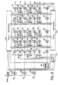
A partir de là, il est possible de concevoir un dispositif d'élimination de pics secondaires tel que celui représenté sur la figure 8.From there, it is possible to design a device for eliminating secondary peaks such as that shown in FIG. 8.
Les amplitudes A1, A2, A3 présentes en sortie de chacune des voies de traitement à chaque temps élémentaire (moment des lois de modulation) sont d'abord appliquées à des portes P de validation 101 à 103 commandées par les temps d'observabilité de chaque suite d'impulsions 11, 12 ou 13 (voir figure 5). Pendant les temps d'observabilité, les amplitudes sont transmises sans modification et, pendant les temps d'inobservabilité, les portes P transmettent une valeur zéro. Après passage dans les portes 101 à 103, les amplitudes sont appliquées à des circuits du type registre à décalage comportant L+1 registres 111, 121 ... 151 pour la voie 1, 113, 123 ... 153 pour la voie 2, etc ..., où L est le nombre de moments de chaque loi de modulation, la progression dans ces registres s'effectuant au rythme des temps élémentaires.The amplitudes A1, A2, A3 present at the output of each of the processing channels at each elementary time (moment of the modulation laws) are first applied to
Par ailleurs, les amplitudes des trois voies sont appliquées à un circuit 104 détecteur de maximum qui fournit sur sa sortie le rang i de la voie présentant l'amplitude maximum à l'instant considéré. Ces amplitudes sont aussi appliquées à un circuit 105 de calcul de seuils dits simultanés qui fournit en réponse au rang et à la valeur de l'amplitude maximum des seuils SIj(O) correspondant aux coefficients à l'instant 0 de l'une des trois configurations possibles (figure 5) selon la voie présentant un maximum. Ces seuils sont comparées aux amplitudes A1 dans les comparateurs S respectifs 108 à 110 pourfoumir un bit de détection D égal à 1 si le seuil est égal ou inférieur à l'amplitude correspondante et à 0 si le seuil est supérieur. Ce bit est ensuite transmis à l'étage suivant par l'intermédiaire d'un registre R' 112, 114, 116. Tous les autres étages sont ensuite identiques et comprennent chacun un circuit de comparaison S' (par exemple 118 à 120 pour l'étage 1) suivi d'un registre R' (par exemple 122, 124, 126 pour l'étage 1).Furthermore, the amplitudes of the three channels are applied to a
Un circuit de comparaison comporte, comme représenté sur la figure 9, deux comparateurs Ca, Cp, recevant l'amplitude A de la voie correspondante retardée de un à L temps élémentaire selon l'étage considéré et un seuil respectif dit antérieur Sa ou postérieur Sd, et une porte "ET" AG recevant les sorties des comparateurs Ca et Cp et le bit de détection D de l'étage précédent et fournissant le nouveau bit de détection D'. Le bit D' vaut 1 si le bit D vaut 1 et si l'amplitude A est supérieure aux deux seuils Sa et Sp. Sinon, il prend la valeur 0.A comparison circuit comprises, as shown in FIG. 9, two comparators Ca, Cp, receiving the amplitude A of the corresponding channel delayed by one to L elementary time depending on the stage considered and a respective threshold called anterior Sa or posterior S d , and an "AND" gate AG receiving the outputs of the comparators Ca and Cp and the detection bit D of the previous stage and supplying the new detection bit D '. Bit D 'is worth 1 if bit D is worth 1 and if the amplitude A is greater than the two thresholds Sa and Sp. Otherwise, it takes the
Les seuils antérieurs, pour les retards R de -1 à -L, sont fournis par un générateur de seuils antérieurs 107 tandis que les seuils postérieurs, pour les retards R de +1 à +L, sont fournis par un générateur de seuils postérieurs 106.The prior thresholds, for delays R from -1 to -L, are provided by an
Les seuils antérieurs sont élaborés à partir des amplitudes à l'entrée du dispositif et du rang de la voie contenant l'amplitude maximum. Les seuils postérieurs sont élaborés à partir des amplitudes apparaissant à la sortie du dispositif ainsi que du rang de la voie contenant en sortie l'amplitude maximum. Ce rang est obtenu en prévoyant une voie parallèle de progression du rang i fourni parle circuit 104 à travers L+1 registres R" 117, 127 ... 157.The previous thresholds are developed from the amplitudes at the input of the device and from the rank of the channel containing the maximum amplitude. The posterior thresholds are developed from the amplitudes appearing at the output of the device as well as from the rank of the channel containing at output the maximum amplitude. This rank is obtained by providing a parallel progression path for rank i supplied by
Les générateurs 106 et 107 sont de structure strictement identique.
Le générateur 107 est représenté partiellement sur la figure 10. Il comprend un circuit de sélection 1070 qui sélectionne, sous le contrôle du rang i venant du circuit 104, l'amplitude maximum Amax reçue à l'entrée. Par ailleurs le rang i adresse, pour chaque étage, une mémoire morte 1071, 1075 ... contenant tous les coefficients Kij pour le retard correspondant à l'étage considéré. Ainsi, la mémoire 1071 contient tous les coefficients Kij(-1) pour toutes les valeurs de i et de j, i correspondant à la voie présentant l'amplitude maximum. Les coefficients Kij sélectionnés (avec j variant de 1 à 3) sont envoyés à des multiplieurs 1072 à 1074,1076 à 1078... qui calculent les produits Kij. Amax = Sij et fournissent donc les valeurs de seuil correspondantes.The
Il est clair que le même circuit (circuit de sélection, mémoire morte et multiplieurs) est prévu pour le circuit 105.It is clear that the same circuit (selection circuit, read-only memory and multipliers) is provided for
Le fonctionnement du dispositif de la figure 8 apparaît ainsi clairement Les amplitudes apparaissant à l'entrée du dispositif servent à calculer les seuils antérieurs qui sont comparés aux amplitudes antérieures correspondantes qui sont présentes dans les divers étages du dispositif, ce qui permet d'annuler les bits de détection d'amplitudes de pics secondaires détectés, lorsque l'amplitude maximum à l'entrée devient plus élevée. De même, les amplitudes apparaissant à la sortie du dispositif servent à calculer les seuils postérieurs qui sont comparés aux amplitudes correspondantes arrivées postérieurement et qui sont présentes dans les divers étages du dispositif ce qui permet d'annuler les bits de détection d'amplitudes de pics secondaires détectés, lorsque l'amplitude maximum à la sortie est notablement plus élevée.The operation of the device of FIG. 8 thus appears clearly. The amplitudes appearing at the input of the device are used to calculate the previous thresholds which are compared to the corresponding previous amplitudes which are present in the various stages of the device, which makes it possible to cancel the secon peak amplitude detection bits detected, when the maximum amplitude at the input becomes higher. Likewise, the amplitudes appearing at the output of the device are used to calculate the posterior thresholds which are compared with the corresponding amplitudes arrived later and which are present in the various stages of the device which makes it possible to cancel the bits for detecting peak amplitudes secondary detected, when the maximum amplitude at the output is significantly higher.
Bien entendu, les exemples de réalisation décrits ne sont nullement limitatifs de l'invention.Of course, the embodiments described are in no way limitative of the invention.
Claims (11)
Applications Claiming Priority (2)
| Application Number | Priority Date | Filing Date | Title |
|---|---|---|---|
| FR8916789A FR2656108B1 (en) | 1989-12-19 | 1989-12-19 | COHERENT IMPULSE RADAR SYSTEM AND METHOD FOR THE DETECTION OF A TARGET HEAD HAVING VERY SHORT-TERM LIGHTNING. |
| FR8916789 | 1989-12-19 |
Publications (1)
| Publication Number | Publication Date |
|---|---|
| EP0434503A1 true EP0434503A1 (en) | 1991-06-26 |
Family
ID=9388675
Family Applications (1)
| Application Number | Title | Priority Date | Filing Date |
|---|---|---|---|
| EP90403543A Withdrawn EP0434503A1 (en) | 1989-12-19 | 1990-12-12 | Coherent pulse radar system and method for detecting a target presenting flashes of a very short duration |
Country Status (3)
| Country | Link |
|---|---|
| US (1) | US5124710A (en) |
| EP (1) | EP0434503A1 (en) |
| FR (1) | FR2656108B1 (en) |
Cited By (3)
| Publication number | Priority date | Publication date | Assignee | Title |
|---|---|---|---|---|
| FR2722005A1 (en) * | 1994-06-30 | 1996-01-05 | Loral Corp | APPARATUS AND METHOD FOR ATTENUATING AMBIGUITS IN PULSE DOPPLER RADARS |
| EP0740165A1 (en) * | 1995-04-25 | 1996-10-30 | Thomson-Csf | Method and device for signal processing for removing ambiguity in a Doppler radar |
| EP2821809A1 (en) * | 2013-07-05 | 2015-01-07 | Thales | Method for detecting at least one target by pulse-Doppler radar with unambiguous measurement of radial velocity and pulse-Doppler radar for implementing such a method |
Families Citing this family (11)
| Publication number | Priority date | Publication date | Assignee | Title |
|---|---|---|---|---|
| NL9101720A (en) * | 1991-10-16 | 1993-05-17 | Hollandse Signaalapparaten Bv | DEVICE FOR DETECTING AND DETERMINATING HELICOPTERS. |
| NL1012373C2 (en) * | 1999-06-17 | 2000-12-19 | Hollandse Signaalapparaten Bv | Radar device. |
| NL1020287C2 (en) * | 2002-04-02 | 2003-10-03 | Thales Nederland Bv | Method for multi-target detection, in particular for use in search radars with multi-beam formation in elevation. |
| US7259714B1 (en) * | 2005-05-04 | 2007-08-21 | Cataldo Thomas J | Unique space time adaptive system (USS) |
| US7522089B2 (en) * | 2006-06-12 | 2009-04-21 | Raytheon Company | Airborne look-down doppler radar tracking of hovering helicopters using rotor features |
| US10514454B1 (en) * | 2014-10-24 | 2019-12-24 | The United States of America, as represented by the Administrator of the Federal Aviation Administration | Techniques for mitigating the effects of complex structures on radar systems |
| JP6376985B2 (en) * | 2015-02-13 | 2018-08-22 | 三菱電機株式会社 | Target detection device |
| GB201510945D0 (en) * | 2015-06-22 | 2015-08-05 | Imp Innovations Ltd | Echo measurement |
| US9952319B2 (en) * | 2015-12-08 | 2018-04-24 | Delphi Technologies, Inc. | Residue cancellation for automated vehicle MIMO radar |
| WO2020189262A1 (en) * | 2019-03-20 | 2020-09-24 | 京セラ株式会社 | Electronic device, electronic device control method, and electronic device control program |
| US20240027577A1 (en) * | 2022-07-20 | 2024-01-25 | Applied Concepts, Inc. | Adaptive fan noise suppression for traffic radar systems |
Citations (5)
| Publication number | Priority date | Publication date | Assignee | Title |
|---|---|---|---|---|
| US3526894A (en) * | 1961-05-18 | 1970-09-01 | Thomson Houston Comp Francaise | Random modulation radar |
| US4275396A (en) * | 1979-10-12 | 1981-06-23 | Jacomini Omar J | Helicopter rotating blade detection system |
| US4513288A (en) * | 1982-03-29 | 1985-04-23 | The United States Of America As Represented By The Secretary Of The Army | Group-complementary code sets for implementing pulse-compression processing with optimum aperiodic autocorrelation and optimum cross-correlation properties |
| EP0187397A1 (en) * | 1984-12-11 | 1986-07-16 | Hollandse Signaalapparaten B.V. | Pulse radar apparatus |
| EP0336273A2 (en) * | 1988-04-02 | 1989-10-11 | Daimler-Benz Aerospace Aktiengesellschaft | Pulse Doppler radar |
Family Cites Families (8)
| Publication number | Priority date | Publication date | Assignee | Title |
|---|---|---|---|---|
| US3733603A (en) * | 1968-07-31 | 1973-05-15 | Us Army | Radar target identification system |
| IT1074498B (en) * | 1976-09-16 | 1985-04-20 | Selenia Ind Elettroniche | IMPROVEMENT IN ELEVATION ERROR REDUCTION SYSTEMS FOR LOW ALTITUDE TARGET TRACKING RADAR |
| FR2463938B1 (en) * | 1979-08-23 | 1985-07-26 | Labo Cent Telecommunicat | RADAR DOPPLER TO DETECT AND LOCATE HELICOPTERS |
| US4389647A (en) * | 1980-12-22 | 1983-06-21 | The United States Of America As Represented By The Secretary Of The Army | Doppler discrimination of aircraft targets |
| US4499467A (en) * | 1982-04-14 | 1985-02-12 | The United States Of America As Represented By The Secretary Of The Army | Doppler radar sets with target direction sensing capability |
| US4635058A (en) * | 1983-12-14 | 1987-01-06 | Rca Corporation | Vehicle identification system using radar and acoustic information |
| US4816833A (en) * | 1987-06-16 | 1989-03-28 | Westinghouse Electric Corp. | Pulse doppler surveillance post signal processing and scan to scan correlation |
| US4920347A (en) * | 1988-05-07 | 1990-04-24 | Mitsubishi Denki Kabushiki Kaisha | Pulse doppler radar system |
-
1989
- 1989-12-19 FR FR8916789A patent/FR2656108B1/en not_active Expired - Fee Related
-
1990
- 1990-12-12 EP EP90403543A patent/EP0434503A1/en not_active Withdrawn
- 1990-12-17 US US07/628,165 patent/US5124710A/en not_active Expired - Fee Related
Patent Citations (5)
| Publication number | Priority date | Publication date | Assignee | Title |
|---|---|---|---|---|
| US3526894A (en) * | 1961-05-18 | 1970-09-01 | Thomson Houston Comp Francaise | Random modulation radar |
| US4275396A (en) * | 1979-10-12 | 1981-06-23 | Jacomini Omar J | Helicopter rotating blade detection system |
| US4513288A (en) * | 1982-03-29 | 1985-04-23 | The United States Of America As Represented By The Secretary Of The Army | Group-complementary code sets for implementing pulse-compression processing with optimum aperiodic autocorrelation and optimum cross-correlation properties |
| EP0187397A1 (en) * | 1984-12-11 | 1986-07-16 | Hollandse Signaalapparaten B.V. | Pulse radar apparatus |
| EP0336273A2 (en) * | 1988-04-02 | 1989-10-11 | Daimler-Benz Aerospace Aktiengesellschaft | Pulse Doppler radar |
Non-Patent Citations (1)
| Title |
|---|
| PROCEEDING OF THE 1988 IEEE NATIONAL RADAR CONFERENCE, Ann Arbor, Michigan, 20-21 avril 1988, pages 194-199, IEEE, New York, US; F.F. KRETSCHMER, Jr. et al.: "New radar pulse compression waveforms" * |
Cited By (7)
| Publication number | Priority date | Publication date | Assignee | Title |
|---|---|---|---|---|
| FR2722005A1 (en) * | 1994-06-30 | 1996-01-05 | Loral Corp | APPARATUS AND METHOD FOR ATTENUATING AMBIGUITS IN PULSE DOPPLER RADARS |
| WO1996000909A1 (en) * | 1994-06-30 | 1996-01-11 | Loral Corporation | Apparatus and method for mitigating range-doppler ambiguities in pulse-doppler radars |
| AU699274B2 (en) * | 1994-06-30 | 1998-11-26 | Lockheed Martin Tactical Systems Inc. | Apparatus and method for mitigating range-doppler ambiguities in pulse -doppler radars |
| EP0740165A1 (en) * | 1995-04-25 | 1996-10-30 | Thomson-Csf | Method and device for signal processing for removing ambiguity in a Doppler radar |
| FR2733600A1 (en) * | 1995-04-25 | 1996-10-31 | Thomson Csf | SIGNAL PROCESSING METHOD AND DEVICE FOR RAISING THE AMBIGUITY SPEED OF A DOPPLER RADAR |
| EP2821809A1 (en) * | 2013-07-05 | 2015-01-07 | Thales | Method for detecting at least one target by pulse-Doppler radar with unambiguous measurement of radial velocity and pulse-Doppler radar for implementing such a method |
| FR3008191A1 (en) * | 2013-07-05 | 2015-01-09 | Thales Sa | METHOD FOR DETECTING AT LEAST ONE PULSE DOPPLER RADAR TARGET WITH NON-AMBIGED RADIAL SPEED MEASUREMENT AND DOPPLER PULSE RADAR FOR IMPLEMENTING SUCH A METHOD |
Also Published As
| Publication number | Publication date |
|---|---|
| FR2656108B1 (en) | 1993-02-05 |
| US5124710A (en) | 1992-06-23 |
| FR2656108A1 (en) | 1991-06-21 |
Similar Documents
| Publication | Publication Date | Title |
|---|---|---|
| EP0818691B1 (en) | Method and apparatus for detecting targets for wide band non-ambiguous pulse doppler radar | |
| EP0120775B1 (en) | Ranging and doppler measuring laser apparatus using pulse compression | |
| EP0434503A1 (en) | Coherent pulse radar system and method for detecting a target presenting flashes of a very short duration | |
| EP0681190B1 (en) | Method and systemfor discrete radar detection | |
| FR2718249A1 (en) | Radar distance measuring method and device. | |
| FR2540314A1 (en) | METHOD FOR INITIALIZING COEFFICIENT FILTERS IN A NEAR-AND-NEAR ECHO CANCELLATION DEVICE AND DEVICE FOR IMPLEMENTING SAID METHOD | |
| FR2731853A1 (en) | SAMPLING DEMODULATION METHOD AND DEVICE, IN PARTICULAR FOR A MOTOR VEHICLE ALARM SYSTEM | |
| FR2737307A1 (en) | DISTANCE MEASUREMENT SYSTEM | |
| EP1706757B1 (en) | Method and receiver apparatus for wireless data communication with ultra wide band time coded signals | |
| EP0493189B1 (en) | Digitally coded impulse signal processing | |
| EP3198299B1 (en) | Radar detection method and radar implementing said method | |
| EP0546623A1 (en) | Ultrasonic echograph for measuring high velocities of blood flows | |
| EP0849889B1 (en) | Method of multipath signal reception | |
| FR2640761A1 (en) | ||
| EP0098183B1 (en) | Proximity radar | |
| FR2894097A1 (en) | Data e.g. JPEG image, transmission method, involves transmitting long packets and short packets, where each packet has acquisition preamble, actual data items and assembly of fixed non-modulated carriers | |
| FR2632421A1 (en) | Transmitter and receiver of an identification message | |
| EP1058402A1 (en) | Method for processing an impulse response with adaptive threshold and corresponding receiver | |
| EP0010481A1 (en) | Method of and device for displaying moving targets, in particular in a variable PRF radar | |
| EP1075122A1 (en) | Measurement of impulse response for a pseudo-random code which changes according to the slip factor | |
| EP0064900A1 (en) | Electromagnetic system with correlation detection and proximity fuze using said system | |
| FR2888336A1 (en) | Target`s false echo elimination method for phase coded continuous wave radar, involves determining whether gate provides signal during subsequent utilization of one of codes for each of gates remote from radar | |
| FR2639102A1 (en) | DEVICE FOR GUIDING A MISSILE | |
| EP1252722B1 (en) | Cdma radiocommunication method with access codes and corresponding receiver | |
| FR3125888A1 (en) | METHOD FOR OPTIMIZING THE DETERMINATION OF THE DISTANCE OF A TARGET IN RELATION TO A PHASE ENCODED RADAR IN PULSE MODE |
Legal Events
| Date | Code | Title | Description |
|---|---|---|---|
| PUAI | Public reference made under article 153(3) epc to a published international application that has entered the european phase |
Free format text: ORIGINAL CODE: 0009012 |
|
| AK | Designated contracting states |
Kind code of ref document: A1 Designated state(s): DE GB |
|
| 17P | Request for examination filed |
Effective date: 19911220 |
|
| STAA | Information on the status of an ep patent application or granted ep patent |
Free format text: STATUS: THE APPLICATION IS DEEMED TO BE WITHDRAWN |
|
| 18D | Application deemed to be withdrawn |
Effective date: 19930701 |