EP0439278A2 - Method and apparatus for recording data transitions - Google Patents
Method and apparatus for recording data transitions Download PDFInfo
- Publication number
- EP0439278A2 EP0439278A2 EP91300354A EP91300354A EP0439278A2 EP 0439278 A2 EP0439278 A2 EP 0439278A2 EP 91300354 A EP91300354 A EP 91300354A EP 91300354 A EP91300354 A EP 91300354A EP 0439278 A2 EP0439278 A2 EP 0439278A2
- Authority
- EP
- European Patent Office
- Prior art keywords
- data
- servo
- field
- disk
- recording
- Prior art date
- Legal status (The legal status is an assumption and is not a legal conclusion. Google has not performed a legal analysis and makes no representation as to the accuracy of the status listed.)
- Granted
Links
- 238000000034 method Methods 0.000 title claims abstract description 17
- 230000007704 transition Effects 0.000 title claims description 22
- 238000012546 transfer Methods 0.000 claims description 8
- 230000001360 synchronised effect Effects 0.000 claims description 2
- 238000010586 diagram Methods 0.000 description 4
- 238000013461 design Methods 0.000 description 3
- 238000012937 correction Methods 0.000 description 2
- 230000005381 magnetic domain Effects 0.000 description 2
- 230000003287 optical effect Effects 0.000 description 2
- 238000011084 recovery Methods 0.000 description 2
- 235000016639 Syzygium aromaticum Nutrition 0.000 description 1
- 244000223014 Syzygium aromaticum Species 0.000 description 1
- 238000013459 approach Methods 0.000 description 1
- 239000002131 composite material Substances 0.000 description 1
- 239000013078 crystal Substances 0.000 description 1
- 125000004122 cyclic group Chemical group 0.000 description 1
- 230000003247 decreasing effect Effects 0.000 description 1
- 230000001934 delay Effects 0.000 description 1
- 238000001514 detection method Methods 0.000 description 1
- 238000005516 engineering process Methods 0.000 description 1
- 230000008014 freezing Effects 0.000 description 1
- 238000007710 freezing Methods 0.000 description 1
- 238000005259 measurement Methods 0.000 description 1
- 238000012552 review Methods 0.000 description 1
- 238000012795 verification Methods 0.000 description 1
Images

Classifications
-
- G—PHYSICS
- G11—INFORMATION STORAGE
- G11B—INFORMATION STORAGE BASED ON RELATIVE MOVEMENT BETWEEN RECORD CARRIER AND TRANSDUCER
- G11B20/00—Signal processing not specific to the method of recording or reproducing; Circuits therefor
- G11B20/10—Digital recording or reproducing
- G11B20/12—Formatting, e.g. arrangement of data block or words on the record carriers
- G11B20/1201—Formatting, e.g. arrangement of data block or words on the record carriers on tapes
-
- G—PHYSICS
- G11—INFORMATION STORAGE
- G11B—INFORMATION STORAGE BASED ON RELATIVE MOVEMENT BETWEEN RECORD CARRIER AND TRANSDUCER
- G11B21/00—Head arrangements not specific to the method of recording or reproducing
- G11B21/02—Driving or moving of heads
- G11B21/10—Track finding or aligning by moving the head ; Provisions for maintaining alignment of the head relative to the track during transducing operation, i.e. track following
-
- G—PHYSICS
- G11—INFORMATION STORAGE
- G11B—INFORMATION STORAGE BASED ON RELATIVE MOVEMENT BETWEEN RECORD CARRIER AND TRANSDUCER
- G11B5/00—Recording by magnetisation or demagnetisation of a record carrier; Reproducing by magnetic means; Record carriers therefor
- G11B5/48—Disposition or mounting of heads or head supports relative to record carriers ; arrangements of heads, e.g. for scanning the record carrier to increase the relative speed
- G11B5/58—Disposition or mounting of heads or head supports relative to record carriers ; arrangements of heads, e.g. for scanning the record carrier to increase the relative speed with provision for moving the head for the purpose of maintaining alignment of the head relative to the record carrier during transducing operation, e.g. to compensate for surface irregularities of the latter or for track following
- G11B5/584—Disposition or mounting of heads or head supports relative to record carriers ; arrangements of heads, e.g. for scanning the record carrier to increase the relative speed with provision for moving the head for the purpose of maintaining alignment of the head relative to the record carrier during transducing operation, e.g. to compensate for surface irregularities of the latter or for track following for track following on tapes
-
- G—PHYSICS
- G11—INFORMATION STORAGE
- G11B—INFORMATION STORAGE BASED ON RELATIVE MOVEMENT BETWEEN RECORD CARRIER AND TRANSDUCER
- G11B5/00—Recording by magnetisation or demagnetisation of a record carrier; Reproducing by magnetic means; Record carriers therefor
- G11B5/48—Disposition or mounting of heads or head supports relative to record carriers ; arrangements of heads, e.g. for scanning the record carrier to increase the relative speed
- G11B5/58—Disposition or mounting of heads or head supports relative to record carriers ; arrangements of heads, e.g. for scanning the record carrier to increase the relative speed with provision for moving the head for the purpose of maintaining alignment of the head relative to the record carrier during transducing operation, e.g. to compensate for surface irregularities of the latter or for track following
- G11B5/596—Disposition or mounting of heads or head supports relative to record carriers ; arrangements of heads, e.g. for scanning the record carrier to increase the relative speed with provision for moving the head for the purpose of maintaining alignment of the head relative to the record carrier during transducing operation, e.g. to compensate for surface irregularities of the latter or for track following for track following on disks
- G11B5/59633—Servo formatting
-
- G—PHYSICS
- G11—INFORMATION STORAGE
- G11B—INFORMATION STORAGE BASED ON RELATIVE MOVEMENT BETWEEN RECORD CARRIER AND TRANSDUCER
- G11B20/00—Signal processing not specific to the method of recording or reproducing; Circuits therefor
- G11B20/10—Digital recording or reproducing
- G11B20/12—Formatting, e.g. arrangement of data block or words on the record carriers
- G11B20/1217—Formatting, e.g. arrangement of data block or words on the record carriers on discs
- G11B2020/1255—Fixed Block Architecture [FBA] format
-
- G—PHYSICS
- G11—INFORMATION STORAGE
- G11B—INFORMATION STORAGE BASED ON RELATIVE MOVEMENT BETWEEN RECORD CARRIER AND TRANSDUCER
- G11B20/00—Signal processing not specific to the method of recording or reproducing; Circuits therefor
- G11B20/10—Digital recording or reproducing
- G11B20/12—Formatting, e.g. arrangement of data block or words on the record carriers
- G11B2020/1264—Formatting, e.g. arrangement of data block or words on the record carriers wherein the formatting concerns a specific kind of data
- G11B2020/1265—Control data, system data or management information, i.e. data used to access or process user data
- G11B2020/1281—Servo information
- G11B2020/1282—Servo information in embedded servo fields
-
- G—PHYSICS
- G11—INFORMATION STORAGE
- G11B—INFORMATION STORAGE BASED ON RELATIVE MOVEMENT BETWEEN RECORD CARRIER AND TRANSDUCER
- G11B2220/00—Record carriers by type
- G11B2220/20—Disc-shaped record carriers
- G11B2220/25—Disc-shaped record carriers characterised in that the disc is based on a specific recording technology
- G11B2220/2508—Magnetic discs
-
- G—PHYSICS
- G11—INFORMATION STORAGE
- G11B—INFORMATION STORAGE BASED ON RELATIVE MOVEMENT BETWEEN RECORD CARRIER AND TRANSDUCER
- G11B2220/00—Record carriers by type
- G11B2220/90—Tape-like record carriers
Definitions
- This invention relates to methods and means for writing data onto a recording medium containing servo samples, and more particularly to a method and means for increasing the number of servo samples on a recording disk in a disk file or a tape in a tape drive.
- All disk files require some means of determining the radial position of the read-write heads over the disks so that the heads can be accurately positioned over any desired track. Typically this is done by putting servo information on one or more of the disk surfaces for reading by magnetic or optical read heads.
- Some disk files have servo information only on a dedicated surface of one disk in a disk stack. However, more recently the trend is to store this servo information interspersed with the data stored on each disk surface. This latter approach is preferred because it can be implemented at low cost without extra components beyond those required for storing data and because it provides the servo information at the data surface being accessed, thereby eliminating all thermal sources of track misregistration (TMR).
- TMR track misregistration
- each circumferential track on the disk is divided into a number of sectors.
- Each sector consists of a factory written portion and a user written portion.
- the factory written portion is the servo region which contains the servo information and timing information required to mark the start of the sector.
- the user written portion consists of a data region containing the actual data to be stored and possibly an identification (ID) region which identifies the sector and marks bad sectors.
- ID identification
- Fast servo systems require frequent position measurements; i.e., a high servo sample rate.
- a high servo sample rate In sectored servo arrangements, this is achieved by dividing each track on the disk into a large number of small sectors.
- a large fraction of the potential information capacity of the disk file undesirably is used for the space associated with each sector. For example, if the servo sample rate is doubled, it will double all of the non-data space.
- a method of recording data transitions through a recording head along tracks on a recording medium each track incorporating data record portions, in which the data transitions are recorded, interspersed by servo portions in which servo information is prerecorded, and using the servo information to control the position of the recording head and to synchronise the data transitions characterised in that at least one shortened servo portion is provided in each data record portion, the shortened servo portion having prerecorded servo information which is used to control the position of the recording head in the data record portion and the data transitions being recorded phase continuously throughout each data record portion so that the phase of the data transitions at the start of a shortened servo portion is the same as the phase at the end of a shortened servo portion.
- the apparatus comprises a recording and reproducing head, a data controller, a decoding device, timing and control means to count through each data portion to the beginning of each shortened servo portion of a track, a data detector, clocking means synchronised by the data transitions read from the recording medium by the data detector and arranged to transfer data through the decoding device, and switching means to switch off the input to and output from the clocking means during the passage of a shortened servo portion.
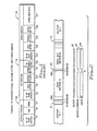
- Fig. 1 is a diagram, not to scale, of a conventional servo sector for a disk file according to the prior art
- Fig.2 is a diagram, not to scale, showing an arrangement of servo sectors according to the invention
- Fig. 3 is a composite diagram, also not to scale, showing how overhead fields are eliminated or reduced in length
- Fig. 4 is a block diagram of a micro servo sector channel according to the invention.
- FIG. 1 There is diagrammatically shown in Fig. 1 the various items of overhead associated with each sector of a conventional prior art disk file formatted in fixed block architecture (FBA).
- Each conventional sector 9 consists of a servo region 10, an ID region 11 and a data region 12, which can be written at different times. These regions consist of various fields, which will now be described.
- micro servo sectors 30 with minimal overhead are inserted on a disk in the data and ECC field 27 for each sector; and only at the beginning of each sector are the conventional servo, ID and data regions 10,11,12 used.
- the micro servo sectors 30 are positioned such that, on each track, the PES fields 17 and 44 for all maxi sectors, respectively, are equally circumferentially spaced.
- a single micro servo sector 30 is inserted on the disk in the middle of data and ECC field 27 of sector N; and a conventional, (hereinafter "maxi") sector 9 including its associated overhead are disposed only at the beginning of sector N.
- maximum a conventional, (hereinafter "maxi") sector 9 including its associated overhead are disposed only at the beginning of sector N.
- a phase continuous clock signal 32 data is written in both portions of the data field 27 to either side of each micro servo sector in a single pass of the disk so that the phase of the data transitions at the start of a microsector is the same as the phase of the end of the microsector.
- each micro servo sector 30 passes by the head (at X), the write current 33 to the head and the data stream 34 and clock input to a data encoder/decoder (ENDEC) 52 (see Fig. 4) are temporarily interrupted.
- ENDEC data encoder/decoder
- the size of some of the fields is reduced and other fields are eliminated, thus substantially reducing the overhead (or non-data bearing portion) in each micro servo sector 30.
- micro servo sector 30 consists of a servo region 40 and a data region 41.
- code constraint portion 42 of write-read and speed field 43 is the longest part of said field. It consists of bits to prevent the decaying write current from writing a transition too close to the last data transition.
- write-read and speed field 15 of maxi sector 9 includes a code constraint portion also; but it is so minute compared to the remainder of field 15 that it is considered negligible.
- Micro servo sectors 30 preferably are read only during seek and read operations, and not during write operations.
- High servo sample rate is required primarily during the seek operation when the head must quickly settle from a rapidly moving condition to accurately follow a given track. By not reading during write operations, it is unnecessary to allow time for the read preamplifier and head magnetic domains to fully recover from their write transients and there is no need to provide time for AGC settling in the read channel.
- the lower bandwidth derived from the conventional maxi sectors is usually acceptable during track following while writing. If a wide bandwidth is required during track following while writing, the micro servo sectors 30 would be read, requiring a somewhat longer write-to-read field 43 for recovery. Since the ENDEC shift register 52 is not clocked while each micro servo sector 30 with its associated overhead fields passes the head, no pad or gap is necessary to assure that it remains in a known state.
- micro servo sector 30 the AM field is eliminated. Timing for position detection is based on time from the address mark field 16 at the beginning of the maxi sector 9, and timing for write and read is based on clock cycles from the beginning of data field 27.
- PES field 44 is shortened and contains both an abbreviated Gray code and position error signal information.
- Gray code is used, as in the prior art, to allow an accurate reading of track number when the servo head is positioned on a track or anywhere between two adjacent tracks.
- the encoding method used may be as described in the July 1982 issue of the IBM Technical Disclosure Bulletin at pp. 776-777. Since the full Gray code in the PES field 17 at the beginning of maxi sector 9 has determined the complete track number position of the head, PES field 44 in the micro servo sector 30 need only verify that the head is positioned at a specific track within a relatively narrow band of tracks adjacent the track determined at the maxi servo sector.
- an abbreviated Gray code is used for such verification. For example, If abbreviated to two bits, the Gray code could identify plus or minus one track within a band of four; and if abbreviated to three bits, to within a band of eight tracks. This abbreviated Gray code further reduces the overhead in the micro servo sectors 30.
- the read-write and speed field 45 is substantially identical with the corresponding field 18 in the maxi sector 9.
- the read VCO does not require a long synchronisation period at the end of the micro servo region.
- the VCO is set to coast through the micro servo region without changing frequency. With most VCO's, this coast can be induced by gating off the detected data from the VCO while the micro servo sector 30 is passing the head.
- the gate is reopened at the beginning of a short VCO sync field 46.
- Field 46 is not written with data massed through the ENDEC encoder as is usual in conventional sectored servo systems. Field 46 and the following code constraint and sync nibble field 47 are generated with logic.
- micro servo sector 30 Since micro servo sector 30 is short, there is only a small phase drift in the VCO with reference to read data.
- VCO sync field 24 In a conventional maxi sector, at the start of the data region 12, VCO sync field 24 must be used to adjust the VCO from an arbitrary phase and to make some adjustment for any frequency difference between a crystal reference clock and the read data.
- VCO sync field 46 can be reduced to from a few bits for a highly stable VCO design to about half those required in the servo region of a maxi sector for a less stable VCO design.
- the ENDEC flush field is also eliminated. This is possible because, at the end of the previous data subfield, clock 32 to the ENDEC is gated off, with the result that the ENDEC holds its state. At the first data clock after sync nibble field 47, ENDEC clock 32 is gated on. Hence, the first encoded data bit is properly clocked into the ENDEC, exactly as if micro servo sector 30 had not been present and the data field had been continuous.
- ENDEC initialisation is not required, there is no need for a sync byte. If the VCO phase drift through each micro servo sector 30 is known to be small enough, the VCO clocks can be counted and gating turned on to start the next data subfield at the correct clock cycle with no sync nibble. The code constraint assures that the last VCO sync transition will not be too close to the first data transition. If the VCO drift is potentially more than one-half clock cycle, however, the exact clock cycle corresponding to the start of the data subfield cannot be determined without a sync nibble.
- the sync nibble need only be some pattern which can be distinguished from the VCO sync pattern. For example, for a 2,7 code, this can be achieved by using a 100100...
- sync nibble detector looks for 000 as the mark indicating the end of the VCO sync field 46. This triggers the gating to start the reading of the following data subfield by the ENDEC.
- micro servo sectors 30 are spaced circumferentially within the data and ECC field 27 for each maxi sector 9.
- Write-read and speed field 43 including code constraint 42 is shortened; the AM (address mark) field is eliminated, the PES field 44 is shortened by use of an abbreviated Gray code; the ENDEC flush field is eliminated; and there is no need for a sync byte.
- Read-write and speed field 45 is essentially the same length as in the servo of conventional sector 9.
- the overhead information for the micro servo sector 30 consists solely of bits containing position information and up to 80 bits to either side thereof.
- a typical micro servo sector 30 for use with the conventional or maxi sector 9 might typically comprise 2 bits in the code constraint portion 42 and 10 bits in the remaining portion of write-read and speed field 43; 130 bits in position error signal field 44; 10 bits in read-write and speed field 45; 30 bits in VCO sync field 46; and 3 bits in code constraint and sync nibble field 47.
- the servo region of a conventional sector 9 may, for example, typically comprise 200 bits in write-read and speed field 15; 25 bits in AM field 16; 170 bits in position error signal field 17; 10 bits in read-write and speed field 18; 140 bits in VCO sync field 19; 8 bits in ENDEC flush field 20; and 8 bits in sync byte field 21.
- micro servo sectors 30 are not overwritten. Also, use of the abbreviated Gray code with micro servo sectors 30 allows them to be used for seek as well as during settling.
- a conventional disk data controller circuit 51 generates the serial bits required for the servo, ID and data regions 10,11,12, respectively, of each maxi sector 9.
- a clock generator 53 generates data clock cycles that are used to transfer uncoded data from disk data controller 51 to an encode section 52a of an encoder/decoder (ENDEC) 52, and to transfer coded data from the ENDEC to a write driver 54 for causing a magnetic head 55 to write data on a magnetic recording disk (not shown).
- ENDEC encoder/decoder
- Timing and control logic 56 closes switches 57,61,62,63 and holds switch 58 in the position in which it is shown in Fig. 4 until said logic, by counting the generated data clock cycles, determines the precise position of the start of the next micro servo sector 30.
- switch 58 is operated to transfer code constraint bits from field 42 (Fig. 3) from timing and control circuit 56 to write driver 54.
- switch 57 is opened to interrupt the data clock cycles from generator 53 to ENDEC encode portion 52a and disk controller 51, thereby freezing the states of both the ENDEC and disk controller.
- Switch 63 is then opened to interrupt the write current to write driver 54 and enable preamp 54 and data detector 59 to read the servo information from micro servo sector 30.
- switch 63 is closed to restore write current; and VCO resync field 46 (if used) and code constraint and sync nibble field 47 are transferred from timing and control circuit 56 to write driver 54.
- Switch 58 is then restored to the position in which it is shown, and switch 57 is closed to resume the transfer of data from disk data controller 51 and ENDEC 52 via head 55 to the disk.
- signals from head 55 are amplified by preamplifier 54 and converted to digital pulses by data detector 59.
- data sync and VCO module 60 a VCO is phase-locked to the detected data pulses and used to synchronise the data to the VCO clock.
- the VCO clock is used to transfer encoded data from data sync and VCO module 60 to disk data controller 51 via the decode section 52b of ENDEC 52.
- Timing and control logic 56 counts VCO clock cycles to determine the precise start position of each micro servo sector 30. At the start of each micro servo sector 30, timing and control logic 56 opens switch 61 to gate off the detected data from sync and VCO module 60. This causes the VCO to coast at a constant frequency.
- switch 62 is opened to stop the VCO clock input to decode section 52b of ENDEC 52 and disk controller 51. This causes the states in the decode section 52b and in disk data controller 51 to be frozen while each micro servo sector passes head 55.
- switch 61 is closed to direct the VCO resync bits to data sync and VCO module 60. This allows the VCO properly to reestablish phase lock with the data.
- switch 62 When the sync nibble is detected by timing and control logic 56, switch 62 is closed to recommence the VCO clock input to ENDEC decode section 52b and to disk data controller 51, thus resuming the transfer of data to the ENDEC and disk data controller.
- the method and means herein disclosed increases the servo position error signal bandwidth for both magnetic and optical direct access storage devices, thereby significantly reducing seek times, settling time and track misregistration for sectored servo disk files.
- thermal track misregistration and misregistration due to actuator tilt to negligible levels high track per inch (TPI) and low cost disk file designs are possible.
- TPI track per inch
- an increased TPI potential may be preferred to a dedicated servo even in a disk file with many disks.
- maxi sections and micro servo sections are substituted for the maxi sectors and micro servo sectors, respectively.
- a plurality of parallel recording tracks on the tape are divided into at least two maxi sections of equal length.
- Each maxi section contains all overhead fields and a data field; and at least one micro servo section containing only a portion of the overhead fields is located within each data field.
- write current to the head is interrupted, as is the stream of data and clock input to a data encoder/decoder.
- write current, data stream and clock input are restored without requiring complete resynchronisation. All overhead information is contained in a combined servo region and ID region of the maxi section.
- Data is written in both portions of a data field to either side of each micro servo section using a phase continuous clock.
- a head data VCO is coasted through each micro servo section without change in frequency, and at the end of said section an abbreviated VCO synchronisation field is generated for resynchronising the VCO with the data.
- Each micro servo section consists solely of bits containing position information and bits to each side thereof for controlling the interruption and restoration of the write current and of the data stream and clock input to the encoder/decoder.
- a method and means has been described for writing data on a recording medium, such as a disk or tape, containing servo samples in such manner that the number of servo samples is increased with a minimal increase in overhead (non-data) regions.
- the tracks on the medium are divided into a plurality of "maxi" sections, each of which in conventional FBA contains all servo and identification (ID) fields with overhead information and also a data field. At least one "micro" servo section containing only a portion of the overhead information is located within each data field.
- micro servo sections contain no timing reference address mark and require no data encoder/decoder (ENDEC) flush or synchronisation byte to resume reading in the portion of the data field following each micro servo section.
- ENDEC data encoder/decoder
- the maxi sections and the micro servo sections are sectors consisting of a plurality of concentric tracks; whereas for a tape drive, the sections consist of a plurality of parallel longitudinally extending tracks. In both cases, however, on each given track ail maxi sectors or sections are of equal length.
Abstract
Description
- This invention relates to methods and means for writing data onto a recording medium containing servo samples, and more particularly to a method and means for increasing the number of servo samples on a recording disk in a disk file or a tape in a tape drive.
- All disk files require some means of determining the radial position of the read-write heads over the disks so that the heads can be accurately positioned over any desired track. Typically this is done by putting servo information on one or more of the disk surfaces for reading by magnetic or optical read heads. Some disk files have servo information only on a dedicated surface of one disk in a disk stack. However, more recently the trend is to store this servo information interspersed with the data stored on each disk surface. This latter approach is preferred because it can be implemented at low cost without extra components beyond those required for storing data and because it provides the servo information at the data surface being accessed, thereby eliminating all thermal sources of track misregistration (TMR).
- In a disk file in a fixed block architecture (FBA) format, each circumferential track on the disk is divided into a number of sectors. Each sector consists of a factory written portion and a user written portion. The factory written portion is the servo region which contains the servo information and timing information required to mark the start of the sector. The user written portion consists of a data region containing the actual data to be stored and possibly an identification (ID) region which identifies the sector and marks bad sectors. A large amount of space, in which no user data can be stored, is associated with each sector.
- Fast servo systems require frequent position measurements; i.e., a high servo sample rate. In sectored servo arrangements, this is achieved by dividing each track on the disk into a large number of small sectors. As a result, a large fraction of the potential information capacity of the disk file undesirably is used for the space associated with each sector. For example, if the servo sample rate is doubled, it will double all of the non-data space.
- The most pertinent prior art of which applicants are aware is an article in the Spring 1988 issue of Computer Technology Review at pp. 45-48. This article describes a method for reducing this non-data space to a very limited degree. To accommodate variable length data records extending over a number of data sectors, an equivalent to the ID region is put in only the first data sector of the record. This saves some space if the data records are long, but none, of course, if the record is less than a sector in length. Each sector may be independently written after leaving the factory; thus, complete resynchronisation is required at each data sector. All other servo fields including full automatic gain control (AGC), write-to-read and read-to-write recovery and synchronisation fields, are therefore still required.
- There is a need for an improved method and means, transparent to the user, for increasing the servo sample rate in either a disk file or a tape drive using the FBA format.
- According to the present invention there is provided a method of recording data transitions through a recording head along tracks on a recording medium, each track incorporating data record portions, in which the data transitions are recorded, interspersed by servo portions in which servo information is prerecorded, and using the servo information to control the position of the recording head and to synchronise the data transitions characterised in that at least one shortened servo portion is provided in each data record portion, the shortened servo portion having prerecorded servo information which is used to control the position of the recording head in the data record portion and the data transitions being recorded phase continuously throughout each data record portion so that the phase of the data transitions at the start of a shortened servo portion is the same as the phase at the end of a shortened servo portion.
- Further according to the present invention there is provided apparatus for reproducing data transitions which have been recorded by the method of the preceding paragraph wherein the apparatus comprises a recording and reproducing head, a data controller, a decoding device, timing and control means to count through each data portion to the beginning of each shortened servo portion of a track, a data detector, clocking means synchronised by the data transitions read from the recording medium by the data detector and arranged to transfer data through the decoding device, and switching means to switch off the input to and output from the clocking means during the passage of a shortened servo portion.
- Fig. 1 is a diagram, not to scale, of a conventional servo sector for a disk file according to the prior art,
- Fig.2 is a diagram, not to scale, showing an arrangement of servo sectors according to the invention,
- Fig. 3 is a composite diagram, also not to scale, showing how overhead fields are eliminated or reduced in length, and
- Fig. 4 is a block diagram of a micro servo sector channel according to the invention.
- There is diagrammatically shown in Fig. 1 the various items of overhead associated with each sector of a conventional prior art disk file formatted in fixed block architecture (FBA). Each
conventional sector 9 consists of aservo region 10, an ID region 11 and adata region 12, which can be written at different times. These regions consist of various fields, which will now be described. - In servo region 10:
- (a) Write-read and
speed field 15 is written at the factory and can be partially rewritten thereafter. It allows time for a drive circuit to switch from write to read. This allows for both logic delays and actual time for a write driver current to decay to zero. To account for variations in rotational speed of the disk, a time is added equal to the relative control speed multiplied by the distance from the previous sector from which absolute timing was last established. Also, shut-off of write current must not begin until a minimum number of clock cycles after the time when the last possible data bit is written to a data encoder/decoder (ENDEC) to assure that the encoded data bits are flushed and written to the disk. In some cases, additional data bits must be sent to the ENDEC to leave its internal shift register in a known state. Finally,field 15 allows time for settling out the transients induced in a read preamplifier by the write current, as well as settling head magnetic domain transients and adjusting an automatic gain control (AGC) in the read channel. - (b) Address mark (AM)
field 16 is written at the factory and must not be overwritten. It is required to identify the beginning of thesector 9. It is an asymchronous, absolute timing reference that provides the basis for locating the other fields. The AM field is frequently implemented as a gap; i.e., as a long period with no magnetic transitions on the disk, followed by a single transition to mark the beginning of a sector. - (c) The position error signal (PES)
field 17 is also written at the factory and must not be overwritten. It contains the information needed to determine the track position of the recording head. It can be encoded in any of a number of ways that are described in the prior art. - In ID region 11:
- (a) Read-write and
speed field 18 is written at the factory and can be partially overwritten after the disk leaves the factory. Fields 19-27 that follow thePES field 17 can be rewritten.Field 18 provides the logic and time needed to ensure thatPES field 17 is not overwritten.Field 18 also provides time for the write current to rise to its full value.Field 18 is typically much shorter than the write-readfield 15.Field 18 and all subsequent fields are normally written using data that passes through a shift register of the ENDEC. - (b) Voltage controlled oscillator synchronisation (VCO sync) field 19 is required to give a variable frequency read clock sufficient time to phase lock to the following
ID field 22. - (c) ENDEC
flush field 20 indicates the number of bits the read channel decoder must receive in order to put it into a known state called ENDEC flush. (Field 20 can range in size from a few bits to close to 10 bytes, depending upon the code used.) - (d)
Sync byte field 21 indicates the sync byte needed to align the read bits on correct byte boundaries. - (e) ID and
CRC field 22 includes as the ID portion a sector identifier and bad sector flag and as the CRC portion a cyclic redundancy check for errors in the reading of the ID. - In data region 12:
- (a) Fields 23-26 correspond to the ID fields 18-21, respectively, with these two exceptions: (1)
field 23 can be completely rewritten; and (2) the function ofsync byte field 26 is to tell the controller when the VCO synchronisation and ENDEC flush end and the real data (which is contained in field 27) begins. - (b) Data and error correction code (ECC)
field 27 stores the user data together with the error correction code. - (c) Each data region in a conventional sectored servo system is completely independent of data regions in the other sectors. They can be written and read at separate times.
- Turning now to Figure 2, there is shown according to the invention, one or more short "micro"
servo sectors 30 with minimal overhead are inserted on a disk in the data andECC field 27 for each sector; and only at the beginning of each sector are the conventional servo, ID anddata regions micro servo sectors 30 are positioned such that, on each track, thePES fields - As illustrated in Fig. 2, a single
micro servo sector 30 is inserted on the disk in the middle of data andECC field 27 of sector N; and a conventional, (hereinafter "maxi")sector 9 including its associated overhead are disposed only at the beginning of sector N. Using a phasecontinuous clock signal 32, data is written in both portions of thedata field 27 to either side of each micro servo sector in a single pass of the disk so that the phase of the data transitions at the start of a microsector is the same as the phase of the end of the microsector. However, while eachmicro servo sector 30 passes by the head (at X), the write current 33 to the head and thedata stream 34 and clock input to a data encoder/decoder (ENDEC) 52 (see Fig. 4) are temporarily interrupted. - As best shown in Fig. 3, the size of some of the fields is reduced and other fields are eliminated, thus substantially reducing the overhead (or non-data bearing portion) in each
micro servo sector 30. - More specifically,
micro servo sector 30 consists of aservo region 40 and a data region 41. Inservo region 40,code constraint portion 42 of write-read and speed field 43 is the longest part of said field. It consists of bits to prevent the decaying write current from writing a transition too close to the last data transition. (By contrast, write-read andspeed field 15 ofmaxi sector 9 includes a code constraint portion also; but it is so minute compared to the remainder offield 15 that it is considered negligible.) By very closely controlling the phase-locked spindle speed of the disk drive motor, the speed variation part of the write-read field 43 can be decreased to a single clock period. -
Micro servo sectors 30 preferably are read only during seek and read operations, and not during write operations. High servo sample rate is required primarily during the seek operation when the head must quickly settle from a rapidly moving condition to accurately follow a given track. By not reading during write operations, it is unnecessary to allow time for the read preamplifier and head magnetic domains to fully recover from their write transients and there is no need to provide time for AGC settling in the read channel. The lower bandwidth derived from the conventional maxi sectors is usually acceptable during track following while writing. If a wide bandwidth is required during track following while writing, themicro servo sectors 30 would be read, requiring a somewhat longer write-to-read field 43 for recovery. Since theENDEC shift register 52 is not clocked while eachmicro servo sector 30 with its associated overhead fields passes the head, no pad or gap is necessary to assure that it remains in a known state. - In
micro servo sector 30, the AM field is eliminated. Timing for position detection is based on time from theaddress mark field 16 at the beginning of themaxi sector 9, and timing for write and read is based on clock cycles from the beginning ofdata field 27. -
PES field 44 is shortened and contains both an abbreviated Gray code and position error signal information. Gray code is used, as in the prior art, to allow an accurate reading of track number when the servo head is positioned on a track or anywhere between two adjacent tracks. The encoding method used may be as described in the July 1982 issue of the IBM Technical Disclosure Bulletin at pp. 776-777. Since the full Gray code in thePES field 17 at the beginning ofmaxi sector 9 has determined the complete track number position of the head,PES field 44 in themicro servo sector 30 need only verify that the head is positioned at a specific track within a relatively narrow band of tracks adjacent the track determined at the maxi servo sector. Since the full track number is thus not required in themicro servo sectors 30, an abbreviated Gray code is used for such verification. For example, If abbreviated to two bits, the Gray code could identify plus or minus one track within a band of four; and if abbreviated to three bits, to within a band of eight tracks. This abbreviated Gray code further reduces the overhead in themicro servo sectors 30. - The read-write and
speed field 45 is substantially identical with thecorresponding field 18 in themaxi sector 9. - Because the data on either side of
micro servo sector 30 including its associated overhead fields is written phase continuously, the read VCO does not require a long synchronisation period at the end of the micro servo region. The VCO is set to coast through the micro servo region without changing frequency. With most VCO's, this coast can be induced by gating off the detected data from the VCO while themicro servo sector 30 is passing the head. The gate is reopened at the beginning of a shortVCO sync field 46.Field 46 is not written with data massed through the ENDEC encoder as is usual in conventional sectored servo systems.Field 46 and the following code constraint and syncnibble field 47 are generated with logic. Sincemicro servo sector 30 is short, there is only a small phase drift in the VCO with reference to read data. In a conventional maxi sector, at the start of thedata region 12,VCO sync field 24 must be used to adjust the VCO from an arbitrary phase and to make some adjustment for any frequency difference between a crystal reference clock and the read data. However, in themicro servo sector 30,VCO sync field 46 can be reduced to from a few bits for a highly stable VCO design to about half those required in the servo region of a maxi sector for a less stable VCO design. - The ENDEC flush field is also eliminated. This is possible because, at the end of the previous data subfield,
clock 32 to the ENDEC is gated off, with the result that the ENDEC holds its state. At the first data clock aftersync nibble field 47,ENDEC clock 32 is gated on. Hence, the first encoded data bit is properly clocked into the ENDEC, exactly as ifmicro servo sector 30 had not been present and the data field had been continuous. - Because ENDEC initialisation is not required, there is no need for a sync byte. If the VCO phase drift through each
micro servo sector 30 is known to be small enough, the VCO clocks can be counted and gating turned on to start the next data subfield at the correct clock cycle with no sync nibble. The code constraint assures that the last VCO sync transition will not be too close to the first data transition. If the VCO drift is potentially more than one-half clock cycle, however, the exact clock cycle corresponding to the start of the data subfield cannot be determined without a sync nibble. The sync nibble need only be some pattern which can be distinguished from the VCO sync pattern. For example, for a 2,7 code, this can be achieved by using a 100100... sync pattern, with one or two extra 0's following as the sync nibble satisfying the coding constraint. The sync nibble detector then looks for 000 as the mark indicating the end of theVCO sync field 46. This triggers the gating to start the reading of the following data subfield by the ENDEC. - It will thus be seen that, with the disk formatted in fixed block architecture, one or more
micro servo sectors 30 are spaced circumferentially within the data andECC field 27 for eachmaxi sector 9. Write-read and speed field 43 includingcode constraint 42 is shortened; the AM (address mark) field is eliminated, thePES field 44 is shortened by use of an abbreviated Gray code; the ENDEC flush field is eliminated; and there is no need for a sync byte. Read-write andspeed field 45 is essentially the same length as in the servo ofconventional sector 9. - The overhead information for the
micro servo sector 30 consists solely of bits containing position information and up to 80 bits to either side thereof. A typicalmicro servo sector 30 for use with the conventional ormaxi sector 9 might typically comprise 2 bits in thecode constraint portion error signal field 44; 10 bits in read-write andspeed field 45; 30 bits inVCO sync field 46; and 3 bits in code constraint and syncnibble field 47. - By contrast, the servo region of a
conventional sector 9 may, for example, typically comprise 200 bits in write-read andspeed field 15; 25 bits inAM field 16; 170 bits in positionerror signal field 17; 10 bits in read-write andspeed field 18; 140 bits in VCO sync field 19; 8 bits in ENDECflush field 20; and 8 bits insync byte field 21. - During a write operation, data is written in
field 27 at one time, and themicro servo sectors 30 are not overwritten. Also, use of the abbreviated Gray code withmicro servo sectors 30 allows them to be used for seek as well as during settling. - As illustrated, a conventional disk data controller circuit 51 generates the serial bits required for the servo, ID and
data regions maxi sector 9. Aclock generator 53 generates data clock cycles that are used to transfer uncoded data from disk data controller 51 to an encodesection 52a of an encoder/decoder (ENDEC) 52, and to transfer coded data from the ENDEC to awrite driver 54 for causing amagnetic head 55 to write data on a magnetic recording disk (not shown). - Timing and control
logic 56 closes switches 57,61,62,63 and holdsswitch 58 in the position in which it is shown in Fig. 4 until said logic, by counting the generated data clock cycles, determines the precise position of the start of the nextmicro servo sector 30. - As each
micro servo sector 30 movespart head 55,switch 58 is operated to transfer code constraint bits from field 42 (Fig. 3) from timing andcontrol circuit 56 to writedriver 54. Concurrently, switch 57 is opened to interrupt the data clock cycles fromgenerator 53 to ENDEC encodeportion 52a and disk controller 51, thereby freezing the states of both the ENDEC and disk controller. Switch 63 is then opened to interrupt the write current to writedriver 54 and enablepreamp 54 anddata detector 59 to read the servo information frommicro servo sector 30. AfterPES field 44passes head 55, switch 63 is closed to restore write current; and VCO resync field 46 (if used) and code constraint and syncnibble field 47 are transferred from timing andcontrol circuit 56 to writedriver 54.Switch 58 is then restored to the position in which it is shown, and switch 57 is closed to resume the transfer of data from disk data controller 51 andENDEC 52 viahead 55 to the disk. - During reading of data, signals from
head 55 are amplified bypreamplifier 54 and converted to digital pulses bydata detector 59. In data sync andVCO module 60, a VCO is phase-locked to the detected data pulses and used to synchronise the data to the VCO clock. The VCO clock is used to transfer encoded data from data sync andVCO module 60 to disk data controller 51 via thedecode section 52b ofENDEC 52. Timing and controllogic 56 counts VCO clock cycles to determine the precise start position of eachmicro servo sector 30. At the start of eachmicro servo sector 30, timing and controllogic 56 opens switch 61 to gate off the detected data from sync andVCO module 60. This causes the VCO to coast at a constant frequency. Also, while eachmicro servo sector 30passes head 55,switch 62 is opened to stop the VCO clock input to decodesection 52b ofENDEC 52 and disk controller 51. This causes the states in thedecode section 52b and in disk data controller 51 to be frozen while each micro servo sector passeshead 55. At the end of the PES field 44 (Fig. 3) and beginning ofVCO resync field 46,switch 61 is closed to direct the VCO resync bits to data sync andVCO module 60. This allows the VCO properly to reestablish phase lock with the data. When the sync nibble is detected by timing and controllogic 56,switch 62 is closed to recommence the VCO clock input toENDEC decode section 52b and to disk data controller 51, thus resuming the transfer of data to the ENDEC and disk data controller. - The method and means herein disclosed increases the servo position error signal bandwidth for both magnetic and optical direct access storage devices, thereby significantly reducing seek times, settling time and track misregistration for sectored servo disk files. By reducing thermal track misregistration and misregistration due to actuator tilt to negligible levels, high track per inch (TPI) and low cost disk file designs are possible. Finally, because of enhanced performance and reduced cost, an increased TPI potential may be preferred to a dedicated servo even in a disk file with many disks.
- When applied to a tape drive, maxi sections and micro servo sections are substituted for the maxi sectors and micro servo sectors, respectively. A plurality of parallel recording tracks on the tape are divided into at least two maxi sections of equal length. Each maxi section contains all overhead fields and a data field; and at least one micro servo section containing only a portion of the overhead fields is located within each data field. As each micro servo section passes by a recording head, write current to the head is interrupted, as is the stream of data and clock input to a data encoder/decoder. As each micro servo section passes beyond the head, write current, data stream and clock input are restored without requiring complete resynchronisation. All overhead information is contained in a combined servo region and ID region of the maxi section. Data is written in both portions of a data field to either side of each micro servo section using a phase continuous clock. A head data VCO is coasted through each micro servo section without change in frequency, and at the end of said section an abbreviated VCO synchronisation field is generated for resynchronising the VCO with the data.
- No timing reference address mark or encoder/decoder flush or synchronisation byte is required to resume writing the portion of the data field following the micro servo section. Each micro servo section consists solely of bits containing position information and bits to each side thereof for controlling the interruption and restoration of the write current and of the data stream and clock input to the encoder/decoder.
- A method and means has been described for writing data on a recording medium, such as a disk or tape, containing servo samples in such manner that the number of servo samples is increased with a minimal increase in overhead (non-data) regions. The tracks on the medium are divided into a plurality of "maxi" sections, each of which in conventional FBA contains all servo and identification (ID) fields with overhead information and also a data field. At least one "micro" servo section containing only a portion of the overhead information is located within each data field.
- As each micro servo section passes by an associated recording head, writing and reading of data is temporarily interrupted, but it is resumed, when the micro servo section cloves beyond the head, in such manner as to require minimal resynchronisation of said data during reading.
- Using a phase continuous clock, data is written in both portions of a data field to either side of each micro servo section in one pass of the disk or tape relative to the head. The micro servo sections contain no timing reference address mark and require no data encoder/decoder (ENDEC) flush or synchronisation byte to resume reading in the portion of the data field following each micro servo section.
- As implemented in a disk drive, the maxi sections and the micro servo sections are sectors consisting of a plurality of concentric tracks; whereas for a tape drive, the sections consist of a plurality of parallel longitudinally extending tracks. In both cases, however, on each given track ail maxi sectors or sections are of equal length.
Claims (8)
- A method of recording data transitions through a recording head along tracks on a recording medium, each track incorporating data record portions, in which the data transitions are recorded, interspersed by servo portions in which servo information is prerecorded, and using the servo information to control the position of the recording head and to synchronise the data transitions characterised in that at least one shortened servo portion is provided in each data record portion, the shortened servo portion having prerecorded servo information which is used to control the position of the recording head in the data record portion and the data transitions being recorded phase continuously throughout each data record portion so that the phase of the data transitions at the start of a shortened servo portion is the same as the phase at the end of a shortened servo portion.
- A method according to claim 1 wherein each shortened servo portion includes only position information bits and bits to each side thereof for controlling the interruption and resumption of the writing and reading of data.
- A method according to claim 1 or 2 wherein the recording medium has a fixed block architecture format.
- A method according to claim 1, 2 or 3 wherein the record medium is a disk.
- A method according to claim 1, 2 or 3 wherein the record medium is a tape.
- A data processing apparatus for reproducing data transitions which have been recorded by the method of any one of claims 1 to 3 wherein the apparatus comprises a recording and reproducing head 55, a data controller 51, a decoding device 52b, timing and control means 56 to count through each data portion to the beginning of each shortened servo portion of a track, a data detector 59, clocking means 60 synchronised by the data transitions read from the recording medium by the data detector and arranged to transfer data through the decoding device, and switching means 61, 62 to switch off the input to and output from the clocking means during the passage of a shortened servo portion.
- Apparatus according to claim 6 which is a disk file apparatus incorporating means to rotate a disk relative to the recording and reproducing head.
- Apparatus according to claim 6 which is a tape apparatus incorporating means to move a tape relative to the recording and reproducing head.
Applications Claiming Priority (2)
| Application Number | Priority Date | Filing Date | Title |
|---|---|---|---|
| US07/466,195 US5073834A (en) | 1990-01-17 | 1990-01-17 | Disk file or tape drive with high servo sample rate embedding additional servo sectors within individual data sectors |
| US466195 | 1990-01-17 |
Publications (3)
| Publication Number | Publication Date |
|---|---|
| EP0439278A2 true EP0439278A2 (en) | 1991-07-31 |
| EP0439278A3 EP0439278A3 (en) | 1992-09-02 |
| EP0439278B1 EP0439278B1 (en) | 1995-03-29 |
Family
ID=23850875
Family Applications (1)
| Application Number | Title | Priority Date | Filing Date |
|---|---|---|---|
| EP91300354A Expired - Lifetime EP0439278B1 (en) | 1990-01-17 | 1991-01-17 | Method and apparatus for recording data transitions |
Country Status (10)
| Country | Link |
|---|---|
| US (1) | US5073834A (en) |
| EP (1) | EP0439278B1 (en) |
| JP (1) | JPH03232165A (en) |
| KR (1) | KR940006889B1 (en) |
| CN (1) | CN1022870C (en) |
| AU (1) | AU637439B2 (en) |
| BR (1) | BR9100033A (en) |
| CA (1) | CA2030872C (en) |
| DE (1) | DE69108418T2 (en) |
| PE (1) | PE28991A1 (en) |
Cited By (4)
| Publication number | Priority date | Publication date | Assignee | Title |
|---|---|---|---|---|
| EP0590878A2 (en) * | 1992-09-30 | 1994-04-06 | Quantum Corporation | Data block sequencing using ID after embedded servo sector in disk drive |
| EP0631277A2 (en) * | 1993-06-22 | 1994-12-28 | Quantum Corporation | ID-less data sector format and data controller for disk drive |
| EP0676753A2 (en) | 1990-01-17 | 1995-10-11 | International Business Machines Corporation | Data recording and reproducing apparatus |
| WO2010063684A1 (en) * | 2008-12-01 | 2010-06-10 | Xyratex Technology Limited | Measuring a signal with a spin stand |
Families Citing this family (33)
| Publication number | Priority date | Publication date | Assignee | Title |
|---|---|---|---|---|
| US5592348A (en) * | 1991-05-17 | 1997-01-07 | Adaptec, Inc. | Method and structure for locating and skipping over servo bursts on a magnetic disk |
| JP3248194B2 (en) * | 1991-06-24 | 2002-01-21 | ソニー株式会社 | Magnetic disk recording / reproducing device |
| JP2625609B2 (en) * | 1991-07-10 | 1997-07-02 | インターナショナル・ビジネス・マシーンズ・コーポレイション | Disk storage device |
| JPH07176168A (en) * | 1991-09-24 | 1995-07-14 | Kalok Corp | Large-capacity thin disk drive system, disk drive assembly and assembly method |
| US5596738A (en) * | 1992-01-31 | 1997-01-21 | Teac Corporation | Peripheral device control system using changeable firmware in a single flash memory |
| US5396376A (en) * | 1992-03-23 | 1995-03-07 | Conner Peripherals, Inc. | Multi-track embedded servo recording format and method |
| US5255131A (en) * | 1992-08-13 | 1993-10-19 | International Business Machines Corporation | Asynchronous servo identification/address mark detection for PRML disk drive ssytem |
| US5274509A (en) * | 1992-09-10 | 1993-12-28 | Digital Equipment Corporation | On-the-fly splitting of disk data blocks using timed sampling of a data position indicator |
| JPH06150565A (en) * | 1992-10-30 | 1994-05-31 | Sony Corp | Data recording medium and recording and reproducing device |
| US5422763A (en) * | 1992-11-13 | 1995-06-06 | Teac Corporation | Split field zone data recording |
| US5424881A (en) | 1993-02-01 | 1995-06-13 | Cirrus Logic, Inc. | Synchronous read channel |
| US6025967A (en) * | 1993-08-24 | 2000-02-15 | Imation Corp. | Method of identifying magnetic tape characteristics |
| JP2735791B2 (en) * | 1993-08-26 | 1998-04-02 | インターナショナル・ビジネス・マシーンズ・コーポレイション | Method and apparatus for rotary actuator arc compensation correction in direct access storage (DASD) |
| US5523903A (en) * | 1993-12-23 | 1996-06-04 | International Business Machines Corporation | Sector architecture for fixed block disk drive |
| MY112118A (en) * | 1993-12-23 | 2001-04-30 | Hitachi Global Storage Tech Netherlands B V | System and method for skip-sector mapping in a data recording disk drive. |
| US5452150A (en) * | 1994-06-27 | 1995-09-19 | Minnesota Mining And Manufacturing Company | Data cartridge with magnetic tape markers |
| US5675448A (en) * | 1994-12-08 | 1997-10-07 | Imation Corp. | Track pitch error compensation system for data cartridge tape drives |
| JP3048878B2 (en) * | 1995-03-31 | 2000-06-05 | インターナショナル・ビジネス・マシーンズ・コーポレイション | Information recording medium, head position identification method, and information recording device |
| US6002540A (en) * | 1995-05-18 | 1999-12-14 | International Business Machines Corporation | Method and apparatus for rotary actuator arc compensation correction in a direct access storage device |
| KR0159441B1 (en) * | 1995-08-28 | 1999-01-15 | 김광호 | Disc recording medium and its servo controlling method for high quantity hard disc driver |
| KR100195183B1 (en) | 1995-12-19 | 1999-06-15 | 윤종용 | The extended data field of hard disk drive |
| KR0182979B1 (en) * | 1996-06-05 | 1999-04-15 | 김광호 | Servo information forming method and servo control method |
| US6442730B1 (en) * | 1997-01-27 | 2002-08-27 | Lecroy Corporation | Recording medium failure analysis apparatus and method |
| US6381088B1 (en) | 1998-11-06 | 2002-04-30 | Acorn Technologies, Inc. | Apparatus for developing a dynamic servo signal from data in a magnetic disc drive and method |
| USRE40413E1 (en) * | 1998-11-06 | 2008-07-01 | Purchased Patent Management Llc | Method and apparatus for developing a dynamic servo signal from data |
| US6545836B1 (en) | 1999-11-12 | 2003-04-08 | Acorn Technologies, Inc. | Servo control apparatus and method using absolute value input signals |
| US6594103B1 (en) | 1999-11-12 | 2003-07-15 | Acorn Technologies, Inc. | Read channel generating absolute value servo signal |
| JP3787491B2 (en) * | 2000-11-20 | 2006-06-21 | 株式会社日立グローバルストレージテクノロジーズ | Magnetic disk unit |
| US7102839B2 (en) * | 2003-10-31 | 2006-09-05 | International Business Machines Corporation | Magnetic recording channel utilizing control fields for timing recovery, equalization, amplitude and amplitude asymmetry |
| CN101290621B (en) * | 2007-04-17 | 2011-06-15 | 上海申瑞电力科技股份有限公司 | Safe digital card memory search method |
| CN101743593B (en) * | 2007-12-14 | 2013-07-17 | Lsi公司 | Systems and methods for fly-height control using servo address mark data |
| US8139312B2 (en) | 2010-03-02 | 2012-03-20 | International Business Machines Corporation | Timing alternative intervals within a timing based servo band |
| US9053728B1 (en) * | 2014-11-21 | 2015-06-09 | HGST Netherlands B.V. | Servo systems with PES enhanced integrated servo bursts |
Citations (3)
| Publication number | Priority date | Publication date | Assignee | Title |
|---|---|---|---|---|
| WO1983001858A1 (en) * | 1981-11-16 | 1983-05-26 | Dma Systems Corp | Recording of transducer positioning information |
| EP0170223A1 (en) * | 1984-07-27 | 1986-02-05 | Hitachi, Ltd. | Magnetic recording and reproducing apparatus |
| GB2191627A (en) * | 1986-06-04 | 1987-12-16 | Alps Electric Co Ltd | Adjusting for thermal track offset in head positioning on a disk |
-
1990
- 1990-01-17 US US07/466,195 patent/US5073834A/en not_active Expired - Lifetime
- 1990-11-26 CA CA002030872A patent/CA2030872C/en not_active Expired - Fee Related
- 1990-11-29 JP JP2333478A patent/JPH03232165A/en active Granted
- 1990-12-17 AU AU68120/90A patent/AU637439B2/en not_active Ceased
- 1990-12-17 CN CN90109845A patent/CN1022870C/en not_active Expired - Lifetime
- 1990-12-17 KR KR1019900020771A patent/KR940006889B1/en not_active IP Right Cessation
-
1991
- 1991-01-07 BR BR919100033A patent/BR9100033A/en unknown
- 1991-01-08 PE PE1991180083A patent/PE28991A1/en unknown
- 1991-01-17 EP EP91300354A patent/EP0439278B1/en not_active Expired - Lifetime
- 1991-01-17 DE DE69108418T patent/DE69108418T2/en not_active Expired - Fee Related
Patent Citations (3)
| Publication number | Priority date | Publication date | Assignee | Title |
|---|---|---|---|---|
| WO1983001858A1 (en) * | 1981-11-16 | 1983-05-26 | Dma Systems Corp | Recording of transducer positioning information |
| EP0170223A1 (en) * | 1984-07-27 | 1986-02-05 | Hitachi, Ltd. | Magnetic recording and reproducing apparatus |
| GB2191627A (en) * | 1986-06-04 | 1987-12-16 | Alps Electric Co Ltd | Adjusting for thermal track offset in head positioning on a disk |
Cited By (9)
| Publication number | Priority date | Publication date | Assignee | Title |
|---|---|---|---|---|
| EP0676753A2 (en) | 1990-01-17 | 1995-10-11 | International Business Machines Corporation | Data recording and reproducing apparatus |
| EP0681287A2 (en) | 1990-01-17 | 1995-11-08 | International Business Machines Corporation | Magnetic recording disk |
| EP0590878A2 (en) * | 1992-09-30 | 1994-04-06 | Quantum Corporation | Data block sequencing using ID after embedded servo sector in disk drive |
| EP0590878A3 (en) * | 1992-09-30 | 1995-09-27 | Quantum Corp | Data block sequencing using id after embedded servo sector in disk drive |
| EP0631277A2 (en) * | 1993-06-22 | 1994-12-28 | Quantum Corporation | ID-less data sector format and data controller for disk drive |
| EP0631277A3 (en) * | 1993-06-22 | 1995-02-22 | Quantum Corp | ID-less data sector format and data controller for disk drive. |
| WO2010063684A1 (en) * | 2008-12-01 | 2010-06-10 | Xyratex Technology Limited | Measuring a signal with a spin stand |
| GB2477668A (en) * | 2008-12-01 | 2011-08-10 | Xyratex Tech Ltd | Measuring a signal with a spin stand |
| US8441904B2 (en) | 2008-12-01 | 2013-05-14 | Xyratex Technology Limited | Method and apparatus for measuring a signal |
Also Published As
| Publication number | Publication date |
|---|---|
| BR9100033A (en) | 1991-10-22 |
| AU6812090A (en) | 1991-07-18 |
| DE69108418D1 (en) | 1995-05-04 |
| JPH03232165A (en) | 1991-10-16 |
| PE28991A1 (en) | 1991-10-29 |
| EP0439278B1 (en) | 1995-03-29 |
| US5073834A (en) | 1991-12-17 |
| KR940006889B1 (en) | 1994-07-28 |
| CN1053507A (en) | 1991-07-31 |
| JPH0576115B2 (en) | 1993-10-21 |
| CN1022870C (en) | 1993-11-24 |
| KR910014913A (en) | 1991-08-31 |
| AU637439B2 (en) | 1993-05-27 |
| EP0439278A3 (en) | 1992-09-02 |
| CA2030872C (en) | 1995-05-16 |
| DE69108418T2 (en) | 1995-10-12 |
Similar Documents
| Publication | Publication Date | Title |
|---|---|---|
| EP0439278B1 (en) | Method and apparatus for recording data transitions | |
| JP2752938B2 (en) | A device for controlling reading and writing of data streams | |
| US5381281A (en) | Disk drive system using multiple embedded quadrature servo fields | |
| US6124994A (en) | System and method for providing nonadjacent redundancy synchronization bytes | |
| US6067206A (en) | Method and apparatus to compensate for servo wedge rotational offset after a head switch | |
| JP2669509B2 (en) | Magnetic head for disk drive | |
| KR100634106B1 (en) | Disk device and disk media | |
| US6388829B1 (en) | High servo sampling disk drive with minimum overhead | |
| JPH04219677A (en) | Method of recovering data | |
| JPH07169186A (en) | Method and apparatus for positioning of beginning of specific data block at inside of user data block segment in disk drive as well as disk drive architecture | |
| US7885027B2 (en) | Magnetic disk drive with error correction | |
| US20030147166A1 (en) | Disk drive with servo synchronous recording | |
| US7511912B2 (en) | Writing multiple servo sector patterns to improve servo sector alignment on multiple surfaces | |
| US7031086B2 (en) | Magnetic recording apparatus, magnetic recording medium and magnetic recording method | |
| US6690524B1 (en) | Data recovery in a disc drive with redundant sync data blocks | |
| US6005728A (en) | Disk recording medium for embodying high capacity hard disk drive | |
| GB2279491A (en) | A magnetic disk drive | |
| US7457896B1 (en) | Automated register data transfer to reduce processing burden on a processing device |
Legal Events
| Date | Code | Title | Description |
|---|---|---|---|
| PUAI | Public reference made under article 153(3) epc to a published international application that has entered the european phase |
Free format text: ORIGINAL CODE: 0009012 |
|
| AK | Designated contracting states |
Kind code of ref document: A2 Designated state(s): DE FR GB IT |
|
| 17P | Request for examination filed |
Effective date: 19911112 |
|
| PUAL | Search report despatched |
Free format text: ORIGINAL CODE: 0009013 |
|
| AK | Designated contracting states |
Kind code of ref document: A3 Designated state(s): DE FR GB IT |
|
| 17Q | First examination report despatched |
Effective date: 19940628 |
|
| GRAA | (expected) grant |
Free format text: ORIGINAL CODE: 0009210 |
|
| AK | Designated contracting states |
Kind code of ref document: B1 Designated state(s): DE FR GB IT |
|
| REF | Corresponds to: |
Ref document number: 69108418 Country of ref document: DE Date of ref document: 19950504 |
|
| ITF | It: translation for a ep patent filed |
Owner name: IBM - DR. ING. FABRIZIO LETTIERI |
|
| ET | Fr: translation filed | ||
| PGFP | Annual fee paid to national office [announced via postgrant information from national office to epo] |
Ref country code: FR Payment date: 19960103 Year of fee payment: 6 |
|
| PLBE | No opposition filed within time limit |
Free format text: ORIGINAL CODE: 0009261 |
|
| STAA | Information on the status of an ep patent application or granted ep patent |
Free format text: STATUS: NO OPPOSITION FILED WITHIN TIME LIMIT |
|
| 26N | No opposition filed | ||
| PGFP | Annual fee paid to national office [announced via postgrant information from national office to epo] |
Ref country code: DE Payment date: 19970128 Year of fee payment: 7 |
|
| PG25 | Lapsed in a contracting state [announced via postgrant information from national office to epo] |
Ref country code: FR Effective date: 19970930 |
|
| REG | Reference to a national code |
Ref country code: FR Ref legal event code: ST |
|
| PG25 | Lapsed in a contracting state [announced via postgrant information from national office to epo] |
Ref country code: DE Free format text: LAPSE BECAUSE OF NON-PAYMENT OF DUE FEES Effective date: 19981001 |
|
| REG | Reference to a national code |
Ref country code: GB Ref legal event code: IF02 |
|
| PG25 | Lapsed in a contracting state [announced via postgrant information from national office to epo] |
Ref country code: IT Free format text: LAPSE BECAUSE OF NON-PAYMENT OF DUE FEES Effective date: 20050117 |
|
| REG | Reference to a national code |
Ref country code: GB Ref legal event code: 746 Effective date: 20081215 |
|
| PGFP | Annual fee paid to national office [announced via postgrant information from national office to epo] |
Ref country code: GB Payment date: 20100125 Year of fee payment: 20 |
|
| REG | Reference to a national code |
Ref country code: GB Ref legal event code: PE20 Expiry date: 20110116 |
|
| PG25 | Lapsed in a contracting state [announced via postgrant information from national office to epo] |
Ref country code: GB Free format text: LAPSE BECAUSE OF EXPIRATION OF PROTECTION Effective date: 20110116 |