EP0450629A1 - Recording and reproducing device and recording medium therefor - Google Patents
Recording and reproducing device and recording medium therefor Download PDFInfo
- Publication number
- EP0450629A1 EP0450629A1 EP91105362A EP91105362A EP0450629A1 EP 0450629 A1 EP0450629 A1 EP 0450629A1 EP 91105362 A EP91105362 A EP 91105362A EP 91105362 A EP91105362 A EP 91105362A EP 0450629 A1 EP0450629 A1 EP 0450629A1
- Authority
- EP
- European Patent Office
- Prior art keywords
- head
- recording medium
- electrodes
- recording
- track patterns
- Prior art date
- Legal status (The legal status is an assumption and is not a legal conclusion. Google has not performed a legal analysis and makes no representation as to the accuracy of the status listed.)
- Granted
Links
- 239000000696 magnetic material Substances 0.000 description 4
- 239000004020 conductor Substances 0.000 description 2
- 230000000694 effects Effects 0.000 description 2
- 238000009434 installation Methods 0.000 description 2
- 238000000034 method Methods 0.000 description 2
- 238000006073 displacement reaction Methods 0.000 description 1
- JEIPFZHSYJVQDO-UHFFFAOYSA-N ferric oxide Chemical compound O=[Fe]O[Fe]=O JEIPFZHSYJVQDO-UHFFFAOYSA-N 0.000 description 1
- 239000011521 glass Substances 0.000 description 1
- 239000000463 material Substances 0.000 description 1
- 230000004048 modification Effects 0.000 description 1
- 238000012986 modification Methods 0.000 description 1
- 230000003287 optical effect Effects 0.000 description 1
- 238000000206 photolithography Methods 0.000 description 1
- 238000000053 physical method Methods 0.000 description 1
- 238000004544 sputter deposition Methods 0.000 description 1
- 239000000126 substance Substances 0.000 description 1
Images


Classifications
-
- E—FIXED CONSTRUCTIONS
- E05—LOCKS; KEYS; WINDOW OR DOOR FITTINGS; SAFES
- E05D—HINGES OR SUSPENSION DEVICES FOR DOORS, WINDOWS OR WINGS
- E05D11/00—Additional features or accessories of hinges
- E05D11/10—Devices for preventing movement between relatively-movable hinge parts
- E05D11/1007—Devices for preventing movement between relatively-movable hinge parts with positive locking
-
- G—PHYSICS
- G11—INFORMATION STORAGE
- G11B—INFORMATION STORAGE BASED ON RELATIVE MOVEMENT BETWEEN RECORD CARRIER AND TRANSDUCER
- G11B11/00—Recording on or reproducing from the same record carrier wherein for these two operations the methods are covered by different main groups of groups G11B3/00 - G11B7/00 or by different subgroups of group G11B9/00; Record carriers therefor
- G11B11/10—Recording on or reproducing from the same record carrier wherein for these two operations the methods are covered by different main groups of groups G11B3/00 - G11B7/00 or by different subgroups of group G11B9/00; Record carriers therefor using recording by magnetic means or other means for magnetisation or demagnetisation of a record carrier, e.g. light induced spin magnetisation; Demagnetisation by thermal or stress means in the presence or not of an orienting magnetic field
- G11B11/105—Recording on or reproducing from the same record carrier wherein for these two operations the methods are covered by different main groups of groups G11B3/00 - G11B7/00 or by different subgroups of group G11B9/00; Record carriers therefor using recording by magnetic means or other means for magnetisation or demagnetisation of a record carrier, e.g. light induced spin magnetisation; Demagnetisation by thermal or stress means in the presence or not of an orienting magnetic field using a beam of light or a magnetic field for recording by change of magnetisation and a beam of light for reproducing, i.e. magneto-optical, e.g. light-induced thermomagnetic recording, spin magnetisation recording, Kerr or Faraday effect reproducing
- G11B11/1055—Disposition or mounting of transducers relative to record carriers
- G11B11/10576—Disposition or mounting of transducers relative to record carriers with provision for moving the transducers for maintaining alignment or spacing relative to the carrier
-
- G—PHYSICS
- G11—INFORMATION STORAGE
- G11B—INFORMATION STORAGE BASED ON RELATIVE MOVEMENT BETWEEN RECORD CARRIER AND TRANSDUCER
- G11B11/00—Recording on or reproducing from the same record carrier wherein for these two operations the methods are covered by different main groups of groups G11B3/00 - G11B7/00 or by different subgroups of group G11B9/00; Record carriers therefor
- G11B11/10—Recording on or reproducing from the same record carrier wherein for these two operations the methods are covered by different main groups of groups G11B3/00 - G11B7/00 or by different subgroups of group G11B9/00; Record carriers therefor using recording by magnetic means or other means for magnetisation or demagnetisation of a record carrier, e.g. light induced spin magnetisation; Demagnetisation by thermal or stress means in the presence or not of an orienting magnetic field
- G11B11/105—Recording on or reproducing from the same record carrier wherein for these two operations the methods are covered by different main groups of groups G11B3/00 - G11B7/00 or by different subgroups of group G11B9/00; Record carriers therefor using recording by magnetic means or other means for magnetisation or demagnetisation of a record carrier, e.g. light induced spin magnetisation; Demagnetisation by thermal or stress means in the presence or not of an orienting magnetic field using a beam of light or a magnetic field for recording by change of magnetisation and a beam of light for reproducing, i.e. magneto-optical, e.g. light-induced thermomagnetic recording, spin magnetisation recording, Kerr or Faraday effect reproducing
- G11B11/1055—Disposition or mounting of transducers relative to record carriers
- G11B11/1058—Flying heads
-
- G—PHYSICS
- G11—INFORMATION STORAGE
- G11B—INFORMATION STORAGE BASED ON RELATIVE MOVEMENT BETWEEN RECORD CARRIER AND TRANSDUCER
- G11B21/00—Head arrangements not specific to the method of recording or reproducing
- G11B21/02—Driving or moving of heads
- G11B21/08—Track changing or selecting during transducing operation
- G11B21/081—Access to indexed tracks or parts of continuous track
- G11B21/083—Access to indexed tracks or parts of continuous track on discs
- G11B21/085—Access to indexed tracks or parts of continuous track on discs with track following of accessed part
-
- G—PHYSICS
- G11—INFORMATION STORAGE
- G11B—INFORMATION STORAGE BASED ON RELATIVE MOVEMENT BETWEEN RECORD CARRIER AND TRANSDUCER
- G11B21/00—Head arrangements not specific to the method of recording or reproducing
- G11B21/02—Driving or moving of heads
- G11B21/10—Track finding or aligning by moving the head ; Provisions for maintaining alignment of the head relative to the track during transducing operation, i.e. track following
-
- G—PHYSICS
- G11—INFORMATION STORAGE
- G11B—INFORMATION STORAGE BASED ON RELATIVE MOVEMENT BETWEEN RECORD CARRIER AND TRANSDUCER
- G11B5/00—Recording by magnetisation or demagnetisation of a record carrier; Reproducing by magnetic means; Record carriers therefor
- G11B5/48—Disposition or mounting of heads or head supports relative to record carriers ; arrangements of heads, e.g. for scanning the record carrier to increase the relative speed
- G11B5/54—Disposition or mounting of heads or head supports relative to record carriers ; arrangements of heads, e.g. for scanning the record carrier to increase the relative speed with provision for moving the head into or out of its operative position or across tracks
- G11B5/55—Track change, selection or acquisition by displacement of the head
- G11B5/5521—Track change, selection or acquisition by displacement of the head across disk tracks
- G11B5/5526—Control therefor; circuits, track configurations or relative disposition of servo-information transducers and servo-information tracks for control thereof
-
- G—PHYSICS
- G11—INFORMATION STORAGE
- G11B—INFORMATION STORAGE BASED ON RELATIVE MOVEMENT BETWEEN RECORD CARRIER AND TRANSDUCER
- G11B5/00—Recording by magnetisation or demagnetisation of a record carrier; Reproducing by magnetic means; Record carriers therefor
- G11B5/48—Disposition or mounting of heads or head supports relative to record carriers ; arrangements of heads, e.g. for scanning the record carrier to increase the relative speed
- G11B5/58—Disposition or mounting of heads or head supports relative to record carriers ; arrangements of heads, e.g. for scanning the record carrier to increase the relative speed with provision for moving the head for the purpose of maintaining alignment of the head relative to the record carrier during transducing operation, e.g. to compensate for surface irregularities of the latter or for track following
- G11B5/596—Disposition or mounting of heads or head supports relative to record carriers ; arrangements of heads, e.g. for scanning the record carrier to increase the relative speed with provision for moving the head for the purpose of maintaining alignment of the head relative to the record carrier during transducing operation, e.g. to compensate for surface irregularities of the latter or for track following for track following on disks
Definitions
- the data surfaces B are provided with radial servo sectors C, a substantial data capacity at the data surface B is reduced.
- the number of servo sectors C must be increased, doing this to provide better tracking may compromise the high capacity of the data surfaces B.
- a recording and reproducing apparatus comprises: a recording medium having track patterns physically formed thereon in advance and further provided with an electrically conducting layer corresponding to the track patterns, an additional information pattern of an electrostatic capacitance type being arranged between the track patterns of the recording medium, a slider part of a read/write head associated with an apparatus for reading information from the recording medium being provided with at least a pair of electrostatic capacitance sensing electrodes opposing the electrically conducting layer of the recording medium so as to control tracking of the head and at the same time, the increased electrostatic capacitance of the additional information pattern is extracted as additional information.
- an electrostatic capacitance generated between the pair of electrodes and the electrical conducting layers of the medium is detected, tracking error data corresponding to the detected capacitance is calculated, the tracking error data is then fed back to a drive circuit for an arm supporting the head and tracking of the head is controlled according to the fed back tracking error data such that the center of the head coincides with the center of the track patterns in real time.
- the pair of electrodes 50 and 51 are formed situated the side surface of the recording medium by the slider part 31 of the head 3 in such a way as they may oppositely face both side portions in a diameteral direction of one track pattern of the plurality of track patterns 10 opposing against the head element 30. That is, as shown in Fig. 5, under a condition in which the head element 30 oppositely faces against one track pattern 10 while its center is being coincided with a center of one track pattern 10 in its diameteral direction, the opposing areas S1 and S2 of the pair of electrodes 50 and 51 are extended from the recording medium surface of the slider part 31 to the side surface of the head element at both sides of the head element 30.
- Each of the lead patterns 52 and 53 is connected to the input terminal of the electrostatic capacitance sensor 5 shown in Fig. 1 through flexible lead lines 54 and 55, respectively.
- the recording medium 1 is installed on the spindle 2, thereby a plurality of track patterns 10 become an earth potential through the contact pattern 13.
- Driving of the spindle 2 and input of track moving information to the control circuit 41 cause the head 3 to be floated on the recording medium 1 under an operative condition in which the head element 30 oppositely faces against one of a plurality of track patterns 10 in the recording medium 1, as shown in Figs. 5 and 6, a pair of electrodes 50 and 51 opposite.y face against one track pattern 10.
- d is an amount of floating operation
- ⁇ is a dielectric constant of air.
- the electrostatic capacitances C1 and C2 are detected to calculate the tracking error e t not influenced by variation of the floating amount d, this calculated tracking error e t is fed back from the calculation means 6 to the drive circuit 42.
- the drive circuit may supply an electrical power added with the tracking error e t got from the calculation means 6 to the track position instruction from the control circuit 41 to the voice coil motor 43, thereby the operating arm 40 may operate to cause the electrostatic capacitances C1 and C2 to be equal in real time.
- the head element 30 Under a condition in which the head element 30 oppositely faces one track pattern 10 while its center is being coincided with a radial center of one track pattern 10, it is constructed such that the opposing areas S1 and S2 of the pair of electrodes 50, 51 and one track pattern 10 are make equal to each other, so that the tracking error e t is fed back from the calculation means 6 to the drive circuit 42, and the head 3 is controlled for its tracking in such a way that a center of the head element 30 is coincided with a center of the track pattern 10 in real time.
- a second preferred embodiment of the present invention is shown in Figs. 7 to 11.
- a feature of the second preferred embodiment, as shown in Fig. 8, is that electrostatic capacitance type additional information patterns 14 are arranged between the track patterns 10 of the recording medium 1A. As shown in Figs.
- the track patterns 10 are physically formed by material having electrical conducting and magnetic characteristics so as to form the electrical conducting layers corresponding to the track patterns 10 are formed in the recording medium 1A, such that, under a condition in which the head element 30 is oppositely faced against one track pattern 10 while its center is being coincided with a radial center of one track pattern 10, a pair of electrodes 50A and 51A arranged in the slider part 31 may oppose the radial outer part of one track pattern and the radial inner part of its adjoining track pattern 10 and these opposing areas S1 and S2 are equal to each other, that as shown in Fig. 9, the sum C+ calculated at the adder 61 is extracted as additional information.
- the structure of the second preferred embodiment shows that a plurality of track patterns 10 and the additional information patterns 14 as well as the extended part 13a are made of electrical conductive and magnetic material, so that installation of the recording medium 1A on the spindle 2 causes the plurality of track patterns 10 and the additional track patterns 14 to become the earth potential.
- a pair of electrodes 50A and 51A oppositely face one track pattern 10 opposing against the head element 30 and its adjacent track pattern 10, respectively.
- the electrostatic capacitance sensor 5 may detect the electrostatic capacitances C1 and C2 generated between the pair of electrodes 50A and 51A and the two track patterns 10.
- the calculation means 6 may calculate the tracking error e t in response to the detected electrostatic capacitances C1 and C2 as follows;
- the calculation result is fed back to the drive circuit 42 and then the tracking of the head 3 is controlled in such a way that the center of the head element 30 is coincided with the center of one track pattern 10.
- the electrostatic capacitances C1 and C2 are increased by a corresponding area of the pair of electrodes 50A, 51A against the additional information patterns 14 so that, as shown in Fig. 9, the sum C+ calculated by the adder 61 is increased in response to the additional information 14. Accordingly, the sum C+ from the adder 61 is extracted as additional information, and this information can be utilized as an address information showing to what track pattern 10 the head element corresponds.
- Figs. 12 and 13 show a third preferred embodiment according to the present invention.
- the third embodiment include track patterns 10, physically formed or an electro-conductive and magnetic material to construct an electric conductive layer corresponding to the track patterns 10 in the recording medium 1.
- the structure of the third preferred embodiment shows that several track patterns 10 and the contact patterns 13 are made of electrical conductive and magnetic material, so that installation of the recording medium 1 on the spindle 2 causes several track patterns to assume an earth potential. Accordingly, under a condition in which the head element 30 oppositely faces against one of several track patterns 10 or the recording medium 1 to enable a recording and/or reproducing operation to be performed, as shown in Fig.
- an even umber of electrodes more than four 50B, 50C, 50D, 50E, 50F, 51B, 51C, 51D, 51E, and 51F are provided arranges into to equal sets and connected in parallel with the in/out terminal of the electrostatic capacitance sensor 5, so that, as compared with the first and second preferred embodiment, it may detect variation of the electrostatic capacitance of n-times when electrodes of 2.n in number are provided.
- the floating amount (d) of the head 3 from the recording medium 1 is varied or one electrode is small in size or the like, a sufficient S/N can be assured.
- the potential V1 the electrode 50 is kept constant to cause the potential V2 of the electrode 51 to become an amount proportional to a ratio between the opposing area S1 and the opposing area S2. Then, the potential V1 which corresponds to C1 is kept constant and a varying amount of the potential V2 corresponding to C2 is applied as the tracking error e t , thereby the calculation means 6 may be eliminated.
- the recording medium 1B is formed with grooves
- the track pattern 10 composed of electrical conducting and magnetic characteristics is formed on the upper surface of the groove of the disc main body 11B or as shown in Fig. 15, the track pattern 10 composed of electro-conducting and magnetic characteristics is buried flush with the upper surface of the disc main body 11C of the recording medium 1C, or as shown in Figs. 16 and 17, the electrical conducting layer 15A or 15B is placed between the track pattern 10a of magnetic material and the disc main body 11D or 11E of the recording medium 1D or 1E and the contact pattern can be eliminated by forming the disc main body (not shown).
- the present invention can be applied to opto-magnetic type disc recording and reproducing devices in which the head is an optical head.
- the head oppositely faces against one of several track patterns in the recording medium to enable a recording and/or reproducing operation to be carried out, wherein the electrostatic capacitances generated between the electrodes and the electrical conducting layers can be controlled in real time in response to a tracking error value corresponding to the detected electrostatic capacitances.
- the electrostatic capacitances generated between the electrodes and the electrical conducting layers can be controlled in real time in response to a tracking error value corresponding to the detected electrostatic capacitances.
- an increased amount of the electrostatic capacitance in a case that the electrodes pass over the additional information patters this increased electrostatic capacitance can be extracted as additional information such as address information.
Abstract
Description
- The present invention relates generally to a recording and reproducing devices and recording medium therefor.
- Referring to Fig. 18, as is well known, in the sector servo system for tracking in magnetic disk recording and reproducing, some servo sectors C, are arranged in a radial direction at data surfaces B of a disk type recording medium A. Information used for tracking is magnetically written in the servo sectors C.
- However, aforesaid sector servo system has the following drawbacks.
- Since the data surfaces B are provided with radial servo sectors C, a substantial data capacity at the data surface B is reduced. In order to improve an accuracy of head tracking, the number of servo sectors C must be increased, doing this to provide better tracking may compromise the high capacity of the data surfaces B.
- Address information to be used for acknowledging at what track pattern the head is positioned is a servo of dispersed value located only at the servo sectors C, with the result that when the head is positioned between the two servo sectors C, by external disturbance, for example, a displacement in head position may not be corrected.
- It is therefore a principal object of the present invention to provide a recording and reproducing device such as a magnetic disk recording and reproducing device for use in performing recording and/or reproducing operations by situating a head, opposing track patterns physically formed in advance on said recording medium, wherein an electrostatic capacitance is formed between the recording medium and a slider section of the head, the electrostatic capacitance is then detected resulting in that a high volume of the data and highly accurate tracking can be attained.
- In order to accomplish the aforementioned and other objects, a recording and reproducing device comprises: a head, situated opposing track patterns which are physically formed in advance on a recording medium, the recording medium being provided with electrically conducting layers corresponding to the track patterns and a slider part of the head is provided with at least a pair of electrostatic capacitance detecting electrodes opposing aforesaid electrical conducting layer to as to control tracking of the head.
- According to another aspect of the present invention, a recording and reproducing apparatus comprises: a recording medium having track patterns physically formed thereon in advance and further provided with an electrically conducting layer corresponding to the track patterns, an additional information pattern of an electrostatic capacitance type being arranged between the track patterns of the recording medium, a slider part of a read/write head associated with an apparatus for reading information from the recording medium being provided with at least a pair of electrostatic capacitance sensing electrodes opposing the electrically conducting layer of the recording medium so as to control tracking of the head and at the same time, the increased electrostatic capacitance of the additional information pattern is extracted as additional information.
- According to yet another aspect of the present invention, a recording medium is provided on which track patterns are physically formed in advance and an electrostatic capacitance type information pattern is arranged between the track patterns.
- Under an operative condition in which the head of the apparatus is oppositely faced against one of a plurality of track patterns in the recording medium to effect a recording or reproducing operation, an electrostatic capacitance generated between the pair of electrodes and the electrical conducting layers of the medium is detected, tracking error data corresponding to the detected capacitance is calculated, the tracking error data is then fed back to a drive circuit for an arm supporting the head and tracking of the head is controlled according to the fed back tracking error data such that the center of the head coincides with the center of the track patterns in real time.
- The present invention will be understood more fully from the detailed description given herebelow and from the accompanying drawings of the preferred embodiments of the invention. However, the drawings are not intended to imply limitation of the invention to a specific embodiment, but are for explanation and understanding only.
- In the drawings:
- Fig. 1, is a configuration view for showing an entire constitution of the first preferred embodiment of the present invention;
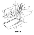
- Fig. 2, is a perspective view for showing a head and a recording medium of the first preferred embodiment;
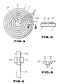
- Fig. 3, is a top plan view for showing a recording medium of the first preferred embodiment;
- Fig. 4, is a sectional view taken along a line III-III of Fig. 3;
- Figs. 5 and 6, are illustrative views for showing an action and effect of the first preferred embodiment of the invention;
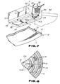
- Fig. 7, is a perspective view for showing the head and the recording medium of the second preferred embodiment of the present invention;
- Fig. 8, is a top plan view for showing a part of the recording medium of the second preferred embodiment of the present invention;
- Fig. 9, is a view of configuration for showing a substantial part of the second preferred embodiment of the present invention;
- Figs. 10 and 11, are illustrative views for showing an action in the second preferred embodiment;
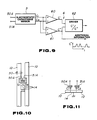
- Fig. 12, is a perspective view for showing the head and the recording medium of the third preferred embodiment of the present invention;
- Fig. 13, is an illustrative view for showing an action of the third preferred embodiment;
- Figs. 14, 15, 16 and 17 are partial sectional views for showing various examples of the recording medium of the present invention.
- Fig. 18 is a top plan view for showing a conventional disc-type recording medium.
- Referring now to the drawings, particularly to Figs. 1-6, Fig. 1 shows a magnetic disk recording and reproducing device, wherein a recording medium 1 is installed at a
spindle 2 and in turn ahead 3 is fixed to an extreme end of a supportingarm 40 of a head driving means 4. Acontrol circuit 41 may output a track position instruction to adrive circuit 42 in response to the track moving information, thedrive circuit 42 may supply an electrical power corresponding to the track position instruction to avoice coil motor 43 so as to move the supportingarm 40. Thehead 3 is moved on the recording medium 1 through an operation of the supportingarm 40 and ahead element 30 of thehead 3 may oppose against one of a plurality of track patterns, physically formed in advance, in the recording medium 1. in turn, if thespindle 2 is rotationally driven with a motor not shown, the recording medium 1 is rotated in a circumferential direction (a direction indicated by an arrow in Fig. 2) of thespindle 2. As shown in Fig. 2, thehead 3 is floated from the recording medium 1 through a dynamic pressure produced by two grooves formed at the lower surface of theslider part 31 of thehead 3, floatingsurfaces 33 positioned outside the two grooves and a viscosity of air through a rotation of the recording medium 1. Date is magnetically recorded in thetrack patterns 10 to which thehead element 30 opposes or the data magnetically recorded in thetrack patterns 10 is reproduced. - As shown in Fig. 1, the magnetic disc recording and reproducing device of the first preferred embodiment is constructed such that the recording medium 1 is provided with electrical conducting layers corresponding to the
track patterns 10 and in turn theslider part 31 of thehead 3 is provided with at least a pair ofelectrodes electrostatic capacitance sensor 5. Electrostatic capacitances C₁ and C₂ generated between the pair ofelectrodes electrostatic capacitance sensor 5. A tracking error (et) corresponding to the sensed electrostatic capacitances C₁ and C₂ is calculated by a calculation means 6. The tracking error (et) of the result of calculation is fed back to thedrive circuit 42 and the tracking of thehead 3 is controlled. - More practically, the electrical conducting layers are constructed by a physical method that, as shown in Figs. 1 to 4, a plurality of
track patterns 10 of different concentric diameters around thefixing hole 12 for thespindle 2 and acontact pattern 13 connecting thesetrack patterns 10 to each other are closely vapor deposited on an entire upper surface of the main body 11 of the disc of the recording medium 1 of glass with layer of magnetic substance having an electrical conduction through a sputtering process, thereafter a resist patterns is formed on the magnetic layer through a photolithography process, a non-required part of the magnetic layer is etched with the resist pattern being applied as a mask and then the resist pattern is removed. An extended pat 13a of thecontact pattern 13 extending from theinnermost track pattern 10 to thefixing hole 12 is contacted with thespindle 2 by installing the recording medium 1 on thespindle 2 of thetrack pattern 10 show an earth potential. - As shown in Figs. 1 and 2, the pair of
electrodes slider part 31 of thehead 3 in such a way as they may oppositely face both side portions in a diameteral direction of one track pattern of the plurality oftrack patterns 10 opposing against thehead element 30. That is, as shown in Fig. 5, under a condition in which thehead element 30 oppositely faces against onetrack pattern 10 while its center is being coincided with a center of onetrack pattern 10 in its diameteral direction, the opposing areas S₁ and S₂ of the pair ofelectrodes slider part 31 to the side surface of the head element at both sides of thehead element 30. Each of thelead patterns electrostatic capacitance sensor 5 shown in Fig. 1 throughflexible lead lines - As shown in Fig. 1, the calculation means 6 is provided with a
subtractor 60 for calculating a pair of electrostatic capacitances C₁ and C₂ of outputs of theelectrostatic sensor 5, anadder 61 for calculating a sum C⁺ of the pair of electrostatic capacitances C₁ and C₂ and adivider 62 for calculating a tracking error et = C⁻/C⁺ as a quotient in which the difference C_ is divided by the sum C⁺, and then the tracking error et corresponding to the electrostatic capacitances C₁ and C₂ is calculated as a geometrical mean of the electrostatic capacitances C₁ and C₂. - According to the configuration of the first preferred embodiment, the recording medium 1 is installed on the
spindle 2, thereby a plurality oftrack patterns 10 become an earth potential through thecontact pattern 13. Driving of thespindle 2 and input of track moving information to thecontrol circuit 41 cause thehead 3 to be floated on the recording medium 1 under an operative condition in which thehead element 30 oppositely faces against one of a plurality oftrack patterns 10 in the recording medium 1, as shown in Figs. 5 and 6, a pair ofelectrodes track pattern 10. As indicated in the followingequations 1 and 2, between the opposing pair ofelectrodes track pattern 10, are generated the electrostatic capacitances C₁ and C₂ corresponding to the opposing areas S₁ and S₂.
where, d is an amount of floating operation and ε is a dielectric constant of air. - The
electrostatic capacitance sensor 5 detects electrostatic capacitances C₁ and C₂ generated between the pair ofelectrodes track pattern 10, and the calculation means 6 composed of thesubtractor 60,adder 61 anddivider 62 may calculate the tracking error et corresponding to the detected electrostatic capacitances C₁ and C₂. The tracking error et calculated by the calculation means 6 becomes as follows in reference to the equations (1) and (2).
- As apparent from this equation (23), the electrostatic capacitances C₁ and C₂ are detected to calculate the tracking error et not influenced by variation of the floating amount d, this calculated tracking error et is fed back from the calculation means 6 to the
drive circuit 42. The drive circuit may supply an electrical power added with the tracking error e t got from the calculation means 6 to the track position instruction from thecontrol circuit 41 to thevoice coil motor 43, thereby theoperating arm 40 may operate to cause the electrostatic capacitances C₁ and C₂ to be equal in real time. That is under a condition in which thehead element 30 oppositely faces onetrack pattern 10 while its center is being coincided with a radial center of onetrack pattern 10, it is constructed such that the opposing areas S₁ and S₂ of the pair ofelectrodes track pattern 10 are make equal to each other, so that the tracking error et is fed back from the calculation means 6 to thedrive circuit 42, and thehead 3 is controlled for its tracking in such a way that a center of thehead element 30 is coincided with a center of thetrack pattern 10 in real time. - A second preferred embodiment of the present invention is shown in Figs. 7 to 11. A feature of the second preferred embodiment, as shown in Fig. 8, is that electrostatic capacitance type
additional information patterns 14 are arranged between thetrack patterns 10 of the recording medium 1A. As shown in Figs. 7 ;and 10, thetrack patterns 10 are physically formed by material having electrical conducting and magnetic characteristics so as to form the electrical conducting layers corresponding to thetrack patterns 10 are formed in the recording medium 1A, such that, under a condition in which thehead element 30 is oppositely faced against onetrack pattern 10 while its center is being coincided with a radial center of onetrack pattern 10, a pair ofelectrodes 50A and 51A arranged in theslider part 31 may oppose the radial outer part of one track pattern and the radial inner part of itsadjoining track pattern 10 and these opposing areas S₁ and S₂ are equal to each other, that as shown in Fig. 9, the sum C⁺ calculated at theadder 61 is extracted as additional information. - Accordingly, the structure of the second preferred embodiment shows that a plurality of
track patterns 10 and theadditional information patterns 14 as well as the extended part 13a are made of electrical conductive and magnetic material, so that installation of the recording medium 1A on thespindle 2 causes the plurality oftrack patterns 10 and theadditional track patterns 14 to become the earth potential. Thus, as shown in Figs. 10 and 11, under a condition in which thehead element 30 is oppositely faced against one of the plurality oftrack patterns 10 of the recording medium 1A to enable a recording and/or reproducing operation to be performed, a pair ofelectrodes 50A and 51A oppositely face onetrack pattern 10 opposing against thehead element 30 and itsadjacent track pattern 10, respectively. Theelectrostatic capacitance sensor 5 may detect the electrostatic capacitances C₁ and C₂ generated between the pair ofelectrodes 50A and 51A and the twotrack patterns 10. The calculation means 6 may calculate the tracking error et in response to the detected electrostatic capacitances C₁ and C₂ as follows;
- The calculation result is fed back to the
drive circuit 42 and then the tracking of thehead 3 is controlled in such a way that the center of thehead element 30 is coincided with the center of onetrack pattern 10. In cooperation with this controlling operation, in a case that the pair ofelectrodes 50A, 51A pass above theadditional information patterns 14, the electrostatic capacitances C₁ and C₂ are increased by a corresponding area of the pair ofelectrodes 50A, 51A against theadditional information patterns 14 so that, as shown in Fig. 9, the sum C⁺ calculated by theadder 61 is increased in response to theadditional information 14. Accordingly, the sum C⁺ from theadder 61 is extracted as additional information, and this information can be utilized as an address information showing to whattrack pattern 10 the head element corresponds. - Figs. 12 and 13 show a third preferred embodiment according to the present invention. Features of the third embodiment include
track patterns 10, physically formed or an electro-conductive and magnetic material to construct an electric conductive layer corresponding to thetrack patterns 10 in the recording medium 1. An even number of electrodes 50B, 50C, 50D, 50E, 50F, 51B, 51C, 51D, 51E, and 51F, numbering more than four are arranged at a side surface of the recording medium of the slider part 31, such that under a condition in which the head element 30 oppositely faces against one track pattern 10 with its center being coincided with a radial center of one track pattern 10, the electrodes 50B, 50C, 50D, 50E, 50F, 51B, 51C, 51D, 51E, and 51F are oppositely faced against four track patterns 10 adjacent to the electrodes and these opposing areas S₃, S₄, S₅, S₆, S₇, S₈, S₉, S₁₀, S₁₁, S₁₂, (S₁ = S₃ + S₄ + S₅ + S₆ + S₇ + S₈ + S₉ + S₁₀ + S₁₁ + S₁₂) become equal to each other, and the electrodes 50B, 50C, 50D, 50E, 50F, 51B, 51C, 51D, 51E, and 51F opposing one side of a radial direction of several track patterns 10 are connected in parallel at one input terminal of the electrostatic capacitance sensor 5, and several of the electrodes 51B, 51C, 51D, 51E and 51F opposing the other sides in the radial directions of several track patterns 10 are connected in parallel with the other input end of the electrostatic capacitance sensor 5. - Accordingly, the structure of the third preferred embodiment shows that
several track patterns 10 and thecontact patterns 13 are made of electrical conductive and magnetic material, so that installation of the recording medium 1 on thespindle 2 causes several track patterns to assume an earth potential. Accordingly, under a condition in which thehead element 30 oppositely faces against one ofseveral track patterns 10 or the recording medium 1 to enable a recording and/or reproducing operation to be performed, as shown in Fig. 13, an even number ofelectrodes track pattern 10 of thehead element 30 and adjoining fourtrack patterns 10, respectively and theelectrostatic capacitance sensor 5 may detect the electrostatic capacitances C₃, C₄, C₅, C₆, C₇, C₈, C₉, C₁₀, C₁₁, C₁₂, (C₁ = C₃ + C₄ + C₅ + C₆ + C₇, C₂ = C₈ + C₉ + C₁₀ + C₁₁ + C₁₂) generated among theelectrodes track patterns 10 and then the calculation means 6 may calculate the tracking error as follows in response to the detected electrostatic capacitances C₁ and C₂.
- The result of calculation is fed back to the
drive circuit 42 and the tracking of thehead 3 is controlled such that the center of thehead element 30 is coincided with the center of onetrack pattern 10 in real time. In the third preferred embodiment, an even umber of electrodes more than four 50B, 50C, 50D, 50E, 50F, 51B, 51C, 51D, 51E, and 51F are provided arranges into to equal sets and connected in parallel with the in/out terminal of theelectrostatic capacitance sensor 5, so that, as compared with the first and second preferred embodiment, it may detect variation of the electrostatic capacitance of n-times when electrodes of 2.n in number are provided. Thus, even in a case that the floating amount (d) of thehead 3 from the recording medium 1 is varied or one electrode is small in size or the like, a sufficient S/N can be assured. - The present invention however, is not limited to the aforesaid embodiments, as shown in Fig. 6, for example, assuming that the potential of the
electrode 50 is defined as V₁, its electrical charge is Q₁, a potential of theelectrode 51 is V₂ and its electrical charge is Q₂, voltages V₁ and V₂ may be defined as;
and further, assuming that Q₁ = Q₂ is attained, the voltage V₂ becomes;
and a ratio of V₂ : V₁ becomes;
- Substituting the equation (4) with the equations (1) and (2) shows the following relation;

- Accordingly, the potential V₁ the
electrode 50 is kept constant to cause the potential V₂ of theelectrode 51 to become an amount proportional to a ratio between the opposing area S₁ and the opposing area S₂. Then, the potential V¹ which corresponds to C¹ is kept constant and a varying amount of the potential V² corresponding to C² is applied as the tracking error et, thereby the calculation means 6 may be eliminated. - As shown in Fig. 14, it is possible that the recording medium 1B is formed with grooves, the
track pattern 10 composed of electrical conducting and magnetic characteristics is formed on the upper surface of the groove of the disc main body 11B or as shown in Fig. 15, thetrack pattern 10 composed of electro-conducting and magnetic characteristics is buried flush with the upper surface of the disc main body 11C of the recording medium 1C, or as shown in Figs. 16 and 17, theelectrical conducting layer 15A or 15B is placed between the track pattern 10a of magnetic material and the disc main body 11D or 11E of the recording medium 1D or 1E and the contact pattern can be eliminated by forming the disc main body (not shown). - In addition, the present invention can be applied to opto-magnetic type disc recording and reproducing devices in which the head is an optical head.
- As described above, according to the present invention, the head oppositely faces against one of several track patterns in the recording medium to enable a recording and/or reproducing operation to be carried out, wherein the electrostatic capacitances generated between the electrodes and the electrical conducting layers can be controlled in real time in response to a tracking error value corresponding to the detected electrostatic capacitances. In addition, in cooperation with tracking control of the head, an increased amount of the electrostatic capacitance in a case that the electrodes pass over the additional information patters, this increased electrostatic capacitance can be extracted as additional information such as address information. Thus, highly accurate tracking, which can endure against a disturbance may be attained and, in addition, it is easily possible to accomplish recording or a high data capacity through effective utilization of surplus area in the recording medium and the narrow tracking possible according to the invention.
- While the present invention has been disclosed in terms of the preferred embodiment in order to facilitate better understanding thereof, it should be appreciated that the invention can be embodied in various ways without departing from the principle of the invention. Therefore, the invention should be understood to include all possible embodiments and modification to the shown embodiments which can be embodied without departing from the principle of the invention as set forth in the appended claims.
Claims (7)
- A recording and/or reproducing apparatus comprising:
head slider means having at least a pair of electrodes on a bottom surface thereof, said electrodes being opposed to conductive stripes provided on a magnetic disc;
head arm means for supporting said head slider means;
head drive means coupled to said head arm means for moving said head slider means by way of said head arm means;
means for detecting capacitances between said electrodes and said conductive stripes;
tracking error signal detecting means connected to said capacitance detecting means for generating tracking error signals; and
means for feeding back said tracking error signal to said head drive means. - A recording and/or reproducing apparatus as set forth in claim 1, wherein said tracking error signal detecting means includes adder means for adding capacitances between said electrodes and said conductive stripes, subtractor means for subtracting capacitances between said electrodes and said conductive stripes, and dividing means for obtaining output ratios of said subtractor means and said adder means.
- A magnetic recording medium comprising:
a base disc;
magnetic tracks provided on said base disc; and
conductive stripes provided on said base disc in relation to said magnetic tracks for detecting tracking error conditions. - A magnetic recording medium as set forth in claim 3, wherein conductive bridge stripes are provided between said adjacent conductive stripes for storing additional information.
- In a recording and reproducing device in which a head is position opposing track patterns physically formed in advance in a recording medium so as to perform a recording and/or reproducing operation, an improvement whereby said recording medium is provided with electro-conductive layers corresponding to the track patterns, and said head is provided with a sliding means and at least two electrodes for sensing an electrostatic capacitance so as to control tracking of the head.
- In a recording and reproducing device in which a head is position opposing track patterns physically formed in advance in a recording medium so as to perform a recording and/or reproducing operation, an improvement whereby said recording medium is provided with electro-conductive layers corresponding to the track patterns, an additional information pattern of an electrostatic capacitance sensing type being arranged between the track patterns of the recording medium, the slider means of said head being provided with at least a pair of electrodes for use in detecting an electrostatic capacitance to oppose said electro-conductive layer, tracking of said head being controlled thereby, and an increased electrostatic capacitance caused by said additional information pattern is extracted as additional data.
- In a recording medium in which the track patterns are physically formed in advance, the improvement comprising: an additional information pattern of an electrostatic capacitance type is arranged between the track patterns.
Applications Claiming Priority (2)
| Application Number | Priority Date | Filing Date | Title |
|---|---|---|---|
| JP91618/90 | 1990-04-06 | ||
| JP2091618A JPH03290816A (en) | 1990-04-06 | 1990-04-06 | Recording and reproducing device and recording medium thereof |
Publications (2)
| Publication Number | Publication Date |
|---|---|
| EP0450629A1 true EP0450629A1 (en) | 1991-10-09 |
| EP0450629B1 EP0450629B1 (en) | 1995-08-09 |
Family
ID=14031564
Family Applications (1)
| Application Number | Title | Priority Date | Filing Date |
|---|---|---|---|
| EP91105362A Expired - Lifetime EP0450629B1 (en) | 1990-04-06 | 1991-04-04 | Recording and reproducing device and recording medium therefor |
Country Status (4)
| Country | Link |
|---|---|
| US (1) | US5488519A (en) |
| EP (1) | EP0450629B1 (en) |
| JP (1) | JPH03290816A (en) |
| DE (1) | DE69111866T2 (en) |
Cited By (5)
| Publication number | Priority date | Publication date | Assignee | Title |
|---|---|---|---|---|
| EP1318513A2 (en) * | 2001-12-06 | 2003-06-11 | Samsung Electronics Co., Ltd. | Information storage apparatus using charge |
| WO2004032117A1 (en) * | 2002-10-03 | 2004-04-15 | Koninklijke Philips Electronics N.V. | Storage system using an array of electro-magnetic sensors |
| WO2004032116A1 (en) * | 2002-10-03 | 2004-04-15 | Koninklijke Philips Electronics N.V. | Read only storage system |
| EP1538608A2 (en) * | 2003-10-20 | 2005-06-08 | Quantum Corporation | Electromagnetic void-sensing probes and position control systems |
| US7649707B2 (en) | 2005-03-18 | 2010-01-19 | Quantum Corporation | Auto-servo tape system and associated recording head |
Families Citing this family (20)
| Publication number | Priority date | Publication date | Assignee | Title |
|---|---|---|---|---|
| US6359746B1 (en) * | 1994-09-14 | 2002-03-19 | Kabushiki Kaisha Toshiba | Magnetic disk drive |
| US6603629B1 (en) | 1996-09-03 | 2003-08-05 | Excel Precision, Inc. | Non-contact servo track writing apparatus and method |
| US6118632A (en) * | 1997-02-12 | 2000-09-12 | International Business Machines Corporation | Magnetic disk stack having laser-bump identifiers on magnetic disks |
| US5991112A (en) * | 1997-03-04 | 1999-11-23 | Excel Precision | Non-contact servotrack writing with phase sensitive detection |
| US6943980B2 (en) * | 2001-02-08 | 2005-09-13 | Seagate Technology Llc | Electrostatic track following using patterned media |
| US7199960B1 (en) * | 2001-12-11 | 2007-04-03 | Maxtor Corporation | Disk drive with AC exciter for head/disk interface |
| CN100359561C (en) * | 2002-10-03 | 2008-01-02 | 皇家飞利浦电子股份有限公司 | Storage system using an array of electro-magnetic sensors |
| US7139152B2 (en) * | 2003-10-20 | 2006-11-21 | Quantum Corporation | Servo methods and systems using existing data structures and optical masks |
| US7149050B2 (en) * | 2003-10-20 | 2006-12-12 | Quantum Corporation | Diffractive position sensors and control systems |
| US7102845B2 (en) * | 2003-10-20 | 2006-09-05 | Quantum Corporation | Servo methods and systems using existing data structures and medium edge position |
| US7136255B2 (en) | 2003-10-20 | 2006-11-14 | Quantum Corporation | Servo methods and systems using masked medium edge position sensors |
| US7116514B2 (en) * | 2003-10-20 | 2006-10-03 | Quantum Corporation | Methods and systems for magnetic recording |
| US7184233B2 (en) * | 2004-06-04 | 2007-02-27 | Quantum Corporation | Dual source tracking servo systems and associated methods |
| US7292407B2 (en) * | 2004-09-30 | 2007-11-06 | Hitachi Global Storage Technologies Netherlands B.V. | Disk drive with support structure for disk-vibration capacitive sensors |
| JP2007213653A (en) * | 2006-02-07 | 2007-08-23 | Fujitsu Ltd | Interval controller |
| US7405896B2 (en) * | 2006-04-26 | 2008-07-29 | Hitachi Global Storage Technologies Netherlands B.V. | Method and apparatus for detecting slider/disk fly-height modulation in a hard disk drive |
| WO2008075432A1 (en) * | 2006-12-21 | 2008-06-26 | Fujitsu Limited | Magnetic recording medium and magnetic recording device |
| US7826169B2 (en) * | 2007-04-25 | 2010-11-02 | Quantum Corporation | Servo error detection and compensation utilizing virtual data tracking servo methods |
| US8482880B2 (en) | 2010-10-19 | 2013-07-09 | Hitachi Global Storage Technologies Netherlands B.V. | Patterned structure in a storage media |
| JP6008588B2 (en) * | 2012-02-29 | 2016-10-19 | 株式会社ディーアンドエムホールディングス | Playback device |
Citations (5)
| Publication number | Priority date | Publication date | Assignee | Title |
|---|---|---|---|---|
| GB2046480A (en) * | 1979-03-27 | 1980-11-12 | Tokyo Shibaura Electric Co | Tracking servo and playback system for video disc |
| EP0162349A2 (en) * | 1984-05-24 | 1985-11-27 | International Business Machines Corporation | A data recording medium |
| EP0222071A2 (en) * | 1985-10-16 | 1987-05-20 | International Business Machines Corporation | Twin track vertical magnetic recording servo control method and apparatus with offset voltage compensation |
| US4701815A (en) * | 1985-03-11 | 1987-10-20 | Sony Corporation | Tracking servo system for disc memory |
| EP0259039A2 (en) * | 1986-08-27 | 1988-03-09 | Sony Corporation | Magnetic disc apparatus |
Family Cites Families (5)
| Publication number | Priority date | Publication date | Assignee | Title |
|---|---|---|---|---|
| JPS57167172A (en) * | 1981-04-07 | 1982-10-14 | Victor Co Of Japan Ltd | High density information recording and reproducing system |
| AU576947B2 (en) * | 1985-03-08 | 1988-09-08 | Sony Corporation | Combination magnetic transducer head |
| US5010430A (en) * | 1987-07-30 | 1991-04-23 | Kabushiki Kaisha Toshiba | Head slider arrangement for magnetic disk storage device |
| JPH01273277A (en) * | 1988-04-25 | 1989-11-01 | Victor Co Of Japan Ltd | Video signal recording and reproducing system using magnetic recording medium with tracking control information obtained by detecting change in electrostatic capacity value |
| JP2863190B2 (en) * | 1989-03-24 | 1999-03-03 | ソニー株式会社 | Manufacturing method of magnetic disk |
-
1990
- 1990-04-06 JP JP2091618A patent/JPH03290816A/en active Pending
-
1991
- 1991-04-04 DE DE69111866T patent/DE69111866T2/en not_active Expired - Fee Related
- 1991-04-04 EP EP91105362A patent/EP0450629B1/en not_active Expired - Lifetime
-
1995
- 1995-06-06 US US08/468,634 patent/US5488519A/en not_active Expired - Fee Related
Patent Citations (5)
| Publication number | Priority date | Publication date | Assignee | Title |
|---|---|---|---|---|
| GB2046480A (en) * | 1979-03-27 | 1980-11-12 | Tokyo Shibaura Electric Co | Tracking servo and playback system for video disc |
| EP0162349A2 (en) * | 1984-05-24 | 1985-11-27 | International Business Machines Corporation | A data recording medium |
| US4701815A (en) * | 1985-03-11 | 1987-10-20 | Sony Corporation | Tracking servo system for disc memory |
| EP0222071A2 (en) * | 1985-10-16 | 1987-05-20 | International Business Machines Corporation | Twin track vertical magnetic recording servo control method and apparatus with offset voltage compensation |
| EP0259039A2 (en) * | 1986-08-27 | 1988-03-09 | Sony Corporation | Magnetic disc apparatus |
Cited By (7)
| Publication number | Priority date | Publication date | Assignee | Title |
|---|---|---|---|---|
| EP1318513A2 (en) * | 2001-12-06 | 2003-06-11 | Samsung Electronics Co., Ltd. | Information storage apparatus using charge |
| EP1318513A3 (en) * | 2001-12-06 | 2005-12-28 | Samsung Electronics Co., Ltd. | Information storage apparatus using charge |
| WO2004032117A1 (en) * | 2002-10-03 | 2004-04-15 | Koninklijke Philips Electronics N.V. | Storage system using an array of electro-magnetic sensors |
| WO2004032116A1 (en) * | 2002-10-03 | 2004-04-15 | Koninklijke Philips Electronics N.V. | Read only storage system |
| EP1538608A2 (en) * | 2003-10-20 | 2005-06-08 | Quantum Corporation | Electromagnetic void-sensing probes and position control systems |
| EP1538608A3 (en) * | 2003-10-20 | 2007-12-19 | Quantum Corporation | Electromagnetic void-sensing probes and position control systems |
| US7649707B2 (en) | 2005-03-18 | 2010-01-19 | Quantum Corporation | Auto-servo tape system and associated recording head |
Also Published As
| Publication number | Publication date |
|---|---|
| DE69111866D1 (en) | 1995-09-14 |
| EP0450629B1 (en) | 1995-08-09 |
| US5488519A (en) | 1996-01-30 |
| DE69111866T2 (en) | 1995-12-07 |
| JPH03290816A (en) | 1991-12-20 |
Similar Documents
| Publication | Publication Date | Title |
|---|---|---|
| EP0450629A1 (en) | Recording and reproducing device and recording medium therefor | |
| EP0326683B1 (en) | Capacitive measurement and control of the fly height of a recording slider | |
| KR0164933B1 (en) | Disk drive and speed control method for transducer | |
| US5132934A (en) | Method and apparatus for storing digital information in the form of stored charges | |
| US6577466B2 (en) | Head with active fly height control | |
| KR100478630B1 (en) | Improved lapping sensor for recording heads | |
| KR900015111A (en) | Servo system for positioning transducer head and its setting method | |
| WO1986006865A1 (en) | Slider assembly with dynamically positionable transducer | |
| CN1947175A (en) | Electrical current measurements at head-disk interface | |
| CN1197267A (en) | Head suspension with self-shielding ingegrated conductor trace array | |
| US4479090A (en) | Circuitry for measuring magnetic head flying characteristics | |
| US4962437A (en) | Thin film servo head employing the inactive transducer coils to cancel write noise from nearby data heads | |
| EP0018156A1 (en) | Recording and replay apparatus employing rotary media | |
| US6219202B1 (en) | Slider suspension assembly and method for attaching a slider to a suspension in a data-recording disk file including a flexible integrated cable having an aperture therein for permitting electrical contact | |
| CN1185855A (en) | Suspension with integrated conductor having controlled capacitance | |
| US5103362A (en) | Method of electrostatically sensing track position information for magnetic recording medium | |
| JPH10512991A (en) | Double identification of disk drive data fields | |
| KR100239151B1 (en) | Recording/reproducing apparatus and recording medium | |
| US3683273A (en) | Method and apparatus for measuring fluid film bearings | |
| JP2976151B2 (en) | Positioning method between recording medium and probe electrode | |
| JPH04109421A (en) | Magnetic disk device | |
| EP0125478B1 (en) | Magnetic record disk with internal servo track | |
| US6721125B2 (en) | Position sensing system for disc drive magnetic microactuators | |
| JPH11176033A (en) | Recording/reproducing head device | |
| US6414814B1 (en) | Method and apparatus for minimizing once per revolution positional errors in single disc servo track writing |
Legal Events
| Date | Code | Title | Description |
|---|---|---|---|
| PUAI | Public reference made under article 153(3) epc to a published international application that has entered the european phase |
Free format text: ORIGINAL CODE: 0009012 |
|
| AK | Designated contracting states |
Kind code of ref document: A1 Designated state(s): DE FR GB |
|
| 17P | Request for examination filed |
Effective date: 19920408 |
|
| 17Q | First examination report despatched |
Effective date: 19940707 |
|
| GRAA | (expected) grant |
Free format text: ORIGINAL CODE: 0009210 |
|
| AK | Designated contracting states |
Kind code of ref document: B1 Designated state(s): DE FR GB |
|
| REF | Corresponds to: |
Ref document number: 69111866 Country of ref document: DE Date of ref document: 19950914 |
|
| ET | Fr: translation filed | ||
| PLBE | No opposition filed within time limit |
Free format text: ORIGINAL CODE: 0009261 |
|
| STAA | Information on the status of an ep patent application or granted ep patent |
Free format text: STATUS: NO OPPOSITION FILED WITHIN TIME LIMIT |
|
| 26N | No opposition filed | ||
| REG | Reference to a national code |
Ref country code: GB Ref legal event code: IF02 |
|
| PGFP | Annual fee paid to national office [announced via postgrant information from national office to epo] |
Ref country code: GB Payment date: 20020404 Year of fee payment: 12 |
|
| PGFP | Annual fee paid to national office [announced via postgrant information from national office to epo] |
Ref country code: FR Payment date: 20020410 Year of fee payment: 12 Ref country code: DE Payment date: 20020410 Year of fee payment: 12 |
|
| PG25 | Lapsed in a contracting state [announced via postgrant information from national office to epo] |
Ref country code: GB Free format text: LAPSE BECAUSE OF NON-PAYMENT OF DUE FEES Effective date: 20030404 |
|
| PG25 | Lapsed in a contracting state [announced via postgrant information from national office to epo] |
Ref country code: DE Free format text: LAPSE BECAUSE OF NON-PAYMENT OF DUE FEES Effective date: 20031101 |
|
| GBPC | Gb: european patent ceased through non-payment of renewal fee |
Effective date: 20030404 |
|
| PG25 | Lapsed in a contracting state [announced via postgrant information from national office to epo] |
Ref country code: FR Free format text: LAPSE BECAUSE OF NON-PAYMENT OF DUE FEES Effective date: 20031231 |
|
| REG | Reference to a national code |
Ref country code: FR Ref legal event code: ST |