EP0466084A1 - SAW electric part and frequency conversion circuit - Google Patents
SAW electric part and frequency conversion circuit Download PDFInfo
- Publication number
- EP0466084A1 EP0466084A1 EP91111361A EP91111361A EP0466084A1 EP 0466084 A1 EP0466084 A1 EP 0466084A1 EP 91111361 A EP91111361 A EP 91111361A EP 91111361 A EP91111361 A EP 91111361A EP 0466084 A1 EP0466084 A1 EP 0466084A1
- Authority
- EP
- European Patent Office
- Prior art keywords
- saw
- frequency
- local oscillation
- saw filter
- signal
- Prior art date
- Legal status (The legal status is an assumption and is not a legal conclusion. Google has not performed a legal analysis and makes no representation as to the accuracy of the status listed.)
- Granted
Links
- 238000006243 chemical reaction Methods 0.000 title claims abstract description 12
- 230000010355 oscillation Effects 0.000 claims abstract description 31
- 239000000758 substrate Substances 0.000 claims abstract description 16
- 239000002131 composite material Substances 0.000 claims abstract 2
- 238000010897 surface acoustic wave method Methods 0.000 description 30
- 238000010586 diagram Methods 0.000 description 3
- 230000003247 decreasing effect Effects 0.000 description 2
- 230000000593 degrading effect Effects 0.000 description 1
- 238000001514 detection method Methods 0.000 description 1
- 238000000034 method Methods 0.000 description 1
Images
Classifications
-
- H—ELECTRICITY
- H03—ELECTRONIC CIRCUITRY
- H03H—IMPEDANCE NETWORKS, e.g. RESONANT CIRCUITS; RESONATORS
- H03H9/00—Networks comprising electromechanical or electro-acoustic devices; Electromechanical resonators
- H03H9/46—Filters
- H03H9/64—Filters using surface acoustic waves
-
- H—ELECTRICITY
- H03—ELECTRONIC CIRCUITRY
- H03B—GENERATION OF OSCILLATIONS, DIRECTLY OR BY FREQUENCY-CHANGING, BY CIRCUITS EMPLOYING ACTIVE ELEMENTS WHICH OPERATE IN A NON-SWITCHING MANNER; GENERATION OF NOISE BY SUCH CIRCUITS
- H03B5/00—Generation of oscillations using amplifier with regenerative feedback from output to input
- H03B5/30—Generation of oscillations using amplifier with regenerative feedback from output to input with frequency-determining element being electromechanical resonator
- H03B5/32—Generation of oscillations using amplifier with regenerative feedback from output to input with frequency-determining element being electromechanical resonator being a piezoelectric resonator
- H03B5/326—Generation of oscillations using amplifier with regenerative feedback from output to input with frequency-determining element being electromechanical resonator being a piezoelectric resonator the resonator being an acoustic wave device, e.g. SAW or BAW device
-
- H—ELECTRICITY
- H03—ELECTRONIC CIRCUITRY
- H03D—DEMODULATION OR TRANSFERENCE OF MODULATION FROM ONE CARRIER TO ANOTHER
- H03D7/00—Transference of modulation from one carrier to another, e.g. frequency-changing
-
- H—ELECTRICITY
- H03—ELECTRONIC CIRCUITRY
- H03B—GENERATION OF OSCILLATIONS, DIRECTLY OR BY FREQUENCY-CHANGING, BY CIRCUITS EMPLOYING ACTIVE ELEMENTS WHICH OPERATE IN A NON-SWITCHING MANNER; GENERATION OF NOISE BY SUCH CIRCUITS
- H03B2200/00—Indexing scheme relating to details of oscillators covered by H03B
- H03B2200/0014—Structural aspects of oscillators
- H03B2200/0018—Structural aspects of oscillators relating to the cutting angle of a crystal, e.g. AT cut quartz
-
- H—ELECTRICITY
- H03—ELECTRONIC CIRCUITRY
- H03B—GENERATION OF OSCILLATIONS, DIRECTLY OR BY FREQUENCY-CHANGING, BY CIRCUITS EMPLOYING ACTIVE ELEMENTS WHICH OPERATE IN A NON-SWITCHING MANNER; GENERATION OF NOISE BY SUCH CIRCUITS
- H03B2200/00—Indexing scheme relating to details of oscillators covered by H03B
- H03B2200/0014—Structural aspects of oscillators
- H03B2200/0022—Structural aspects of oscillators characterised by the substrate, e.g. material
-
- H—ELECTRICITY
- H03—ELECTRONIC CIRCUITRY
- H03B—GENERATION OF OSCILLATIONS, DIRECTLY OR BY FREQUENCY-CHANGING, BY CIRCUITS EMPLOYING ACTIVE ELEMENTS WHICH OPERATE IN A NON-SWITCHING MANNER; GENERATION OF NOISE BY SUCH CIRCUITS
- H03B5/00—Generation of oscillations using amplifier with regenerative feedback from output to input
- H03B5/02—Details
- H03B5/04—Modifications of generator to compensate for variations in physical values, e.g. power supply, load, temperature
-
- H—ELECTRICITY
- H03—ELECTRONIC CIRCUITRY
- H03D—DEMODULATION OR TRANSFERENCE OF MODULATION FROM ONE CARRIER TO ANOTHER
- H03D2200/00—Indexing scheme relating to details of demodulation or transference of modulation from one carrier to another covered by H03D
- H03D2200/0001—Circuit elements of demodulators
- H03D2200/0017—Intermediate frequency filter
-
- H—ELECTRICITY
- H03—ELECTRONIC CIRCUITRY
- H03D—DEMODULATION OR TRANSFERENCE OF MODULATION FROM ONE CARRIER TO ANOTHER
- H03D2200/00—Indexing scheme relating to details of demodulation or transference of modulation from one carrier to another covered by H03D
- H03D2200/0041—Functional aspects of demodulators
- H03D2200/0094—Measures to address temperature induced variations of demodulation
- H03D2200/0096—Measures to address temperature induced variations of demodulation by stabilising the temperature
Definitions
- the present invention relates to an SAW (surface acoustic wave) electric part and a frequency conversion circuit using SAW parts.
- SAW surface acoustic wave
- a plurality of filters are used in a receiver.
- an electric wave received by an antenna 1 is supplied to a frequency mixer 6 through a band-pass filter (BPF) 2 and an amplifier 3.
- a first local oscillation signal generated by a PLL oscillator 4 is supplied to the frequency mixer 6 through a BPF 5.
- the reception signal and the first local oscillation signal are mixed with each other, and a signal having the output frequency is output through a BPF 7, thereby obtaining a first intermediate frequency signal.
- This first intermediate frequency signal is mixed with a second local oscillation signal supplied from a second local oscillation circuit 8, and the output signal is output from a BPF 10 to obtain a second intermediate frequency signal.
- the second intermediate frequency signal is amplified by an amplifier 11 and output.
- the BPF 7 has a proper frequency to be constituted by an SAW filter.
- the BPF 7 can be formed to be compact.
- the BPF using the SAW filter is proposed.
- the SAW filter has degraded temperature characteristics, the center frequency of the filter is shifted due to a change in temperature. Although it is considered that temperature is kept to be constant by a thermostat, this method requires a large space to disable realization of a compact BPF. Although a band-pass width may be increased to cope with the degraded temperature characteristics, when the width is increased, an adjacent channel cannot be cut off. In addition, if a group delay characteristic curve is not flat, a pulse waveform is distorted in digital communications, thereby degrading the reliability of the digital communications. It is difficult to flatten the group delay characteristic curve in a wide range.
- a local oscillation frequency may be changed in accordance with a change in frequency of the filter to always equalize the output frequency of a frequency conversion circuit to the center frequency of the filter.
- the frequency shift of the SAW filter cannot be easily detected. If it can be detected, the local oscillation frequency cannot be easily controlled using the detection result.
- an SAW electric part comprising an SAW filter and an SAW oscillator formed on a substrate having the same temperature characteristics as those of a substrate on which the SAW filter is formed.
- the frequency characteristics of the SAW filter are thermally changed, similar to the frequency characteristics of the SAW oscillator. For this reason, a change in local oscillation frequency has a value close to a change in frequency of the filter, a signal supplied to the filter always has its center frequency.
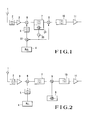
- Fig. 1 is a block diagram showing an embodiment of the present invention, and the same reference numerals as in Fig. 2 denote the same parts in Fig. 1.
- a second local oscillation circuit 20 oscillates a signal having a second local oscillation frequency on the basis of an SAW oscillator 21 formed on a substrate on which an SAW filter 7 is formed.
- a mixer 22 mixes a signal generated by a PLL oscillator 4 with a signal having the second local oscillation frequency.
- An output signal from the mixer 22 is output to a BPF 5, so that a signal from the BPF has a first local oscillation frequency.
- the mixer 22 and the PLL oscillator 4 constitute a frequency conversion circuit.
- a reception frequency is set at 800 MHz
- a first intermediate frequency is set at 80 MHz
- a second intermediate frequency is set at 450 kHz.
- the first local oscillation frequency is set to 720 MHz lower than 800 MHz by 80 MHz
- the second local oscillation frequency is set to 79.55 MHz lower than 80 MHz by 450 kHz
- the oscillation frequency of the PLL oscillator 4 is set to 799.55 MHz lower than 800 MHz by 450 kHz.
- the center frequency of the SAW filter is decreased by 20 kHz from 80 MHz to 79.98 MHz
- the oscillator having the same structure as that of the filter is formed on the substrate on which the filter is formed, a change in frequency of the oscillator has the same characteristics as those of a change in frequency of the filter.
- the second local oscillation frequency is decreased by about 20 kHz from 79.55 MHz to 79.53 MHz.
- This value is equal to the changed frequency of the SAW filter 7. That is, although the center frequency of the SAW filter 7 is changed in accordance with temperatures, the frequency supplied to the filter 7 has also the center frequency of the filter. As a result, the SAW filter 7 outputs a signal having the center frequency of the filter.
- the SAW filter and the SAW oscillator are formed on the same substrate, they may be independently formed on piezoelectric substrates having the same cut angle. In addition, when substrates are formed to have the same temperature characteristics, different types of substrates may be used.
- the present invention can be applied to not only a receiver, but the transmitting side of a transceiver and a signal generator of the receiving side of the transceiver. The present invention can be generally used in a signal generating part.
- the change in frequency of the SAW filter is equal to that of the SAW oscillator, and a signal supplied to the SAW filter is always set to be the center frequency of the filter. Therefore, a special countermeasure against a frequency shift is not required, and an SAW filter having a narrow band width can be advantageously used.
Abstract
Description
- The present invention relates to an SAW (surface acoustic wave) electric part and a frequency conversion circuit using SAW parts.
- In recent years, filters have been used in parts of a device. For example, as shown in Fig. 2, a plurality of filters are used in a receiver. In Fig. 2, an electric wave received by an
antenna 1 is supplied to afrequency mixer 6 through a band-pass filter (BPF) 2 and anamplifier 3. A first local oscillation signal generated by aPLL oscillator 4 is supplied to thefrequency mixer 6 through aBPF 5. The reception signal and the first local oscillation signal are mixed with each other, and a signal having the output frequency is output through aBPF 7, thereby obtaining a first intermediate frequency signal. This first intermediate frequency signal is mixed with a second local oscillation signal supplied from a secondlocal oscillation circuit 8, and the output signal is output from aBPF 10 to obtain a second intermediate frequency signal. The second intermediate frequency signal is amplified by anamplifier 11 and output. - In recent years, lightweight, low-profile, compact devices are preferably used. Compact receivers are strongly demanded. The
BPF 7 has a proper frequency to be constituted by an SAW filter. When the BPF 7 is constituted by the SAW filter, theBPF 7 can be formed to be compact. The BPF using the SAW filter is proposed. - However, the SAW filter has degraded temperature characteristics, the center frequency of the filter is shifted due to a change in temperature. Although it is considered that temperature is kept to be constant by a thermostat, this method requires a large space to disable realization of a compact BPF. Although a band-pass width may be increased to cope with the degraded temperature characteristics, when the width is increased, an adjacent channel cannot be cut off. In addition, if a group delay characteristic curve is not flat, a pulse waveform is distorted in digital communications, thereby degrading the reliability of the digital communications. It is difficult to flatten the group delay characteristic curve in a wide range. On the other hand, a local oscillation frequency may be changed in accordance with a change in frequency of the filter to always equalize the output frequency of a frequency conversion circuit to the center frequency of the filter. However, the frequency shift of the SAW filter cannot be easily detected. If it can be detected, the local oscillation frequency cannot be easily controlled using the detection result.
- It is an object of the present invention to provide a frequency conversion circuit capable of obtaining a stable output even when a frequency shift of a filter occurs due to a change in temperature.
- It is another object of the present invention to provide a frequency conversion circuit capable of using an SAW filter having a narrow band width.
- In order to achieve the above objects according to the present invention, there is provided an SAW electric part comprising an SAW filter and an SAW oscillator formed on a substrate having the same temperature characteristics as those of a substrate on which the SAW filter is formed.
- Since the SAW filter and the SAW oscillator have similar structures, the frequency characteristics of the SAW filter are thermally changed, similar to the frequency characteristics of the SAW oscillator. For this reason, a change in local oscillation frequency has a value close to a change in frequency of the filter, a signal supplied to the filter always has its center frequency.
-
- Fig. 1 is a block diagram showing an embodiment of the present invention; and
- Fig. 2 is a block diagram showing a conventional device.
- Fig. 1 is a block diagram showing an embodiment of the present invention, and the same reference numerals as in Fig. 2 denote the same parts in Fig. 1. Referring to Fig. 1, a second
local oscillation circuit 20 oscillates a signal having a second local oscillation frequency on the basis of anSAW oscillator 21 formed on a substrate on which anSAW filter 7 is formed. Amixer 22 mixes a signal generated by aPLL oscillator 4 with a signal having the second local oscillation frequency. An output signal from themixer 22 is output to aBPF 5, so that a signal from the BPF has a first local oscillation frequency. Note that themixer 22 and thePLL oscillator 4 constitute a frequency conversion circuit. - In the device arranged as described above, it is assumed that a reception frequency is set at 800 MHz, that a first intermediate frequency is set at 80 MHz, and that a second intermediate frequency is set at 450 kHz. In this case, the first local oscillation frequency is set to 720 MHz lower than 800 MHz by 80 MHz, the second local oscillation frequency is set to 79.55 MHz lower than 80 MHz by 450 kHz, and the oscillation frequency of the
PLL oscillator 4 is set to 799.55 MHz lower than 800 MHz by 450 kHz. - At this time, when the center frequency of the SAW filter is decreased by 20 kHz from 80 MHz to 79.98 MHz, since the oscillator having the same structure as that of the filter is formed on the substrate on which the filter is formed, a change in frequency of the oscillator has the same characteristics as those of a change in frequency of the filter. For this reason, the second local oscillation frequency is decreased by about 20 kHz from 79.55 MHz to 79.53 MHz.
- When the oscillation frequency of the
PLL 4 is not influenced by temperatures, the first local oscillation frequency output from theBPF 5 is 799.55 MHz - 79.53 MHz = 720.02 MHz. Therefore, a signal output from themixer 6 has a frequency of 800 MHz - 720.02 MHz = 79.98 MHz. This value is equal to the changed frequency of theSAW filter 7. That is, although the center frequency of theSAW filter 7 is changed in accordance with temperatures, the frequency supplied to thefilter 7 has also the center frequency of the filter. As a result, the SAW filter 7 outputs a signal having the center frequency of the filter. - The first intermediate frequency supplied to a
mixer 9 is changed from 80 MHz to 79.98 MHz, and the second local oscillation frequency is changed from 79.55 MHz to 79.53 MHz. Therefore, a second center frequency is 79.88 MHz - 79.53 MHz = 450 kHz, and this value is equal to the frequency of the SAW filter which is not changed. For this reason, even when the first intermediate frequency is changed, the second intermediate frequency is set to be constant, and a reception operation is normally performed. - In the above embodiment, although the SAW filter and the SAW oscillator are formed on the same substrate, they may be independently formed on piezoelectric substrates having the same cut angle. In addition, when substrates are formed to have the same temperature characteristics, different types of substrates may be used. The present invention can be applied to not only a receiver, but the transmitting side of a transceiver and a signal generator of the receiving side of the transceiver. The present invention can be generally used in a signal generating part.
- As described above, according to the present invention, the change in frequency of the SAW filter is equal to that of the SAW oscillator, and a signal supplied to the SAW filter is always set to be the center frequency of the filter. Therefore, a special countermeasure against a frequency shift is not required, and an SAW filter having a narrow band width can be advantageously used.
Claims (6)
Applications Claiming Priority (2)
| Application Number | Priority Date | Filing Date | Title |
|---|---|---|---|
| JP2179480A JPH0468907A (en) | 1990-07-09 | 1990-07-09 | Saw electronic component and frequency conversion circuit |
| JP179480/90 | 1990-07-09 |
Publications (2)
| Publication Number | Publication Date |
|---|---|
| EP0466084A1 true EP0466084A1 (en) | 1992-01-15 |
| EP0466084B1 EP0466084B1 (en) | 1997-05-14 |
Family
ID=16066578
Family Applications (1)
| Application Number | Title | Priority Date | Filing Date |
|---|---|---|---|
| EP91111361A Expired - Lifetime EP0466084B1 (en) | 1990-07-09 | 1991-07-08 | Frequency conversion circuit. |
Country Status (5)
| Country | Link |
|---|---|
| US (1) | US5410742A (en) |
| EP (1) | EP0466084B1 (en) |
| JP (1) | JPH0468907A (en) |
| KR (1) | KR950012949B1 (en) |
| DE (1) | DE69126068T2 (en) |
Cited By (2)
| Publication number | Priority date | Publication date | Assignee | Title |
|---|---|---|---|---|
| EP0678973A1 (en) * | 1994-04-18 | 1995-10-25 | NEC Corporation | Receiving circuit for generating intermediate frequency signal having frequency characteristics independent of variations in temperature |
| WO2003092161A1 (en) * | 2002-04-23 | 2003-11-06 | Thomson Licensing S.A. | Tuning apparatus |
Families Citing this family (15)
| Publication number | Priority date | Publication date | Assignee | Title |
|---|---|---|---|---|
| US5839062A (en) * | 1994-03-18 | 1998-11-17 | The Regents Of The University Of California | Mixing, modulation and demodulation via electromechanical resonators |
| US5515014A (en) * | 1994-11-30 | 1996-05-07 | At&T Corp. | Interface between SAW filter and Gilbert cell mixer |
| JPH11127052A (en) * | 1997-10-24 | 1999-05-11 | Murata Mfg Co Ltd | Composite filter and radio equipment using it |
| JPH11145771A (en) * | 1997-11-13 | 1999-05-28 | Murata Mfg Co Ltd | Composite filter and radio equipment using the same |
| EP1137178A1 (en) * | 2000-03-22 | 2001-09-26 | Infineon Technologies AG | Circuit comprising a filter and method for operating a circuit comprising a filter |
| DE10116880B4 (en) * | 2001-04-04 | 2010-12-16 | Rohde & Schwarz Gmbh & Co. Kg | A method of optimizing the frequency conditioning train of a radio frequency heterodyne receiver |
| US7448269B2 (en) * | 2003-08-12 | 2008-11-11 | Northwestern University | Scanning near field ultrasound holography |
| US8438927B2 (en) * | 2003-08-12 | 2013-05-14 | Northwestern University | Scanning near field thermoelastic acoustic holography (SNFTAH) |
| WO2009019639A2 (en) * | 2007-08-06 | 2009-02-12 | Koninklijke Philips Electronics N.V. | Crystal-less transceivers |
| JP5136175B2 (en) * | 2008-04-11 | 2013-02-06 | 日本電気株式会社 | Frequency converter and frequency conversion method |
| US9571065B2 (en) | 2014-11-12 | 2017-02-14 | Elwha Llc | Surface acoustic wave device having end-to-end combinable selectable electrode sub-elements |
| US9602077B2 (en) | 2014-11-12 | 2017-03-21 | Elwha Llc | Surface acoustic wave device having selectable electrode elements |
| US9692389B2 (en) | 2014-11-12 | 2017-06-27 | Elwha Llc | Surface acoustic wave device having matrices of combinable selectable electrode sub-elements |
| US9800226B2 (en) | 2014-11-12 | 2017-10-24 | Elwha Llc | Surface acoustic wave device having combinable selectable electrode sub-elements |
| US11251822B1 (en) * | 2020-07-23 | 2022-02-15 | Xilinx, Inc. | Software defined radio (SDR) filter relaxation technique for multiple-input and multiple-output (MIMO) and large antenna array (LAA) applications |
Citations (2)
| Publication number | Priority date | Publication date | Assignee | Title |
|---|---|---|---|---|
| US3787612A (en) * | 1972-07-03 | 1974-01-22 | Zenith Radio Corp | Signal processing system for television receiver having acoustic surface wave devices for improved tuning and video demodulation |
| US4100498A (en) * | 1977-06-20 | 1978-07-11 | The United States Of America As Represented By The Secretary Of The Navy | Discrete chirp frequency synthesizer |
Family Cites Families (11)
| Publication number | Priority date | Publication date | Assignee | Title |
|---|---|---|---|---|
| JPS573910A (en) * | 1980-06-04 | 1982-01-09 | Kawasaki Chishitsu Kk | Extra-high pressure horizontal plate bearing tester for ground |
| JPS57107645A (en) * | 1980-12-25 | 1982-07-05 | Toshiba Corp | Tuner |
| JPS5896351U (en) * | 1981-12-22 | 1983-06-30 | 日本電気株式会社 | antenna sharing device |
| US4489289A (en) * | 1982-04-08 | 1984-12-18 | The United States Of America As Represented By The Secretary Of The Air Force | Saw oscillator with digital compensation for temperature related frequency changes |
| JPS59191921A (en) * | 1983-04-15 | 1984-10-31 | Hitachi Ltd | Oscillation frequency control circuit in tuner |
| DE3443925C1 (en) * | 1984-12-01 | 1986-01-30 | Philips Patentverwaltung Gmbh, 2000 Hamburg | Circuit arrangement for distinguishing the two fields in a television signal |
| JPH0697727B2 (en) * | 1985-03-27 | 1994-11-30 | 株式会社日立製作所 | Surface acoustic wave filter |
| US4739286A (en) * | 1986-10-23 | 1988-04-19 | Tektronix, Inc. | Suppression of radiated harmonics |
| KR880014813A (en) * | 1987-05-20 | 1988-12-24 | 이우에 사또시 | PLL Image Detection Circuit |
| US4871984A (en) * | 1988-06-24 | 1989-10-03 | Raytheon Company | Surface acoustic wave oscillator |
| US4978879A (en) * | 1988-07-27 | 1990-12-18 | Fujitsu Limited | Acoustic surface wave element |
-
1990
- 1990-07-09 JP JP2179480A patent/JPH0468907A/en active Pending
-
1991
- 1991-07-08 DE DE69126068T patent/DE69126068T2/en not_active Expired - Lifetime
- 1991-07-08 EP EP91111361A patent/EP0466084B1/en not_active Expired - Lifetime
- 1991-07-08 KR KR1019910011487A patent/KR950012949B1/en not_active IP Right Cessation
-
1994
- 1994-02-14 US US08/195,904 patent/US5410742A/en not_active Expired - Fee Related
Patent Citations (2)
| Publication number | Priority date | Publication date | Assignee | Title |
|---|---|---|---|---|
| US3787612A (en) * | 1972-07-03 | 1974-01-22 | Zenith Radio Corp | Signal processing system for television receiver having acoustic surface wave devices for improved tuning and video demodulation |
| US4100498A (en) * | 1977-06-20 | 1978-07-11 | The United States Of America As Represented By The Secretary Of The Navy | Discrete chirp frequency synthesizer |
Cited By (2)
| Publication number | Priority date | Publication date | Assignee | Title |
|---|---|---|---|---|
| EP0678973A1 (en) * | 1994-04-18 | 1995-10-25 | NEC Corporation | Receiving circuit for generating intermediate frequency signal having frequency characteristics independent of variations in temperature |
| WO2003092161A1 (en) * | 2002-04-23 | 2003-11-06 | Thomson Licensing S.A. | Tuning apparatus |
Also Published As
| Publication number | Publication date |
|---|---|
| DE69126068D1 (en) | 1997-06-19 |
| JPH0468907A (en) | 1992-03-04 |
| KR950012949B1 (en) | 1995-10-23 |
| DE69126068T2 (en) | 1997-12-04 |
| US5410742A (en) | 1995-04-25 |
| KR920003636A (en) | 1992-02-29 |
| EP0466084B1 (en) | 1997-05-14 |
Similar Documents
| Publication | Publication Date | Title |
|---|---|---|
| EP0466084A1 (en) | SAW electric part and frequency conversion circuit | |
| US5898907A (en) | Radio transmitter-receiver adopting both a single frequency and a double frequency conversion | |
| US5949830A (en) | Small wireless radio | |
| US6104745A (en) | Transceiver for performing time division full duplex spread spectrum communication | |
| JP2009536795A (en) | Device for receiving and / or transmitting radio frequency signals with noise reduction | |
| JP3309904B2 (en) | Wireless transceiver | |
| US6721551B2 (en) | Transmitting and receiving apparatus | |
| US6847811B2 (en) | Receiver circuit compensation for filter response error | |
| US7212794B2 (en) | Receiver with a crystal oscillator having a natural-oscillation frequency set so that a fundamental component and its harmonics are outside the range of a receiving band of a modulated wave signal | |
| US6026114A (en) | Transmitting and receiving apparatus of time division full-duplex spread spectrum communication system | |
| US20080176524A1 (en) | FM transmitter device | |
| KR100700311B1 (en) | Radio communicate method and system | |
| WO2021191970A1 (en) | Transceiver | |
| EP1033818A1 (en) | Signal generating circuit, and transmitter, receiver and transmitting and receiving device using the circuit | |
| KR100630140B1 (en) | Direct frequency conversion device and method in a mobile communication system | |
| JP2007336340A (en) | Fsk transceiver | |
| JP3063346B2 (en) | Wireless transmission device | |
| KR950013304B1 (en) | Cellular phone inter freguency circuit | |
| KR100414924B1 (en) | Radio frequency transmission and reception system using voltage control diode | |
| JP2003243983A (en) | Microwave zone and millimeter-wave zone phase synchronizing oscillator and high frequency transmitter and receiver using the same | |
| JP2003152586A (en) | Radio communications equipment, radio equipment, and radio communication system | |
| JPS62502832A (en) | Improvements regarding FM demodulator | |
| JPH06164445A (en) | Wide-band voltage control oscillation circuit | |
| JPH07235889A (en) | Double superheterodyne circuit | |
| JPH1098398A (en) | Band variable-type radio receiver |
Legal Events
| Date | Code | Title | Description |
|---|---|---|---|
| PUAI | Public reference made under article 153(3) epc to a published international application that has entered the european phase |
Free format text: ORIGINAL CODE: 0009012 |
|
| 17P | Request for examination filed |
Effective date: 19910731 |
|
| AK | Designated contracting states |
Kind code of ref document: A1 Designated state(s): DE FR GB SE |
|
| 17Q | First examination report despatched |
Effective date: 19931013 |
|
| GRAG | Despatch of communication of intention to grant |
Free format text: ORIGINAL CODE: EPIDOS AGRA |
|
| RTI1 | Title (correction) | ||
| GRAH | Despatch of communication of intention to grant a patent |
Free format text: ORIGINAL CODE: EPIDOS IGRA |
|
| GRAH | Despatch of communication of intention to grant a patent |
Free format text: ORIGINAL CODE: EPIDOS IGRA |
|
| GRAA | (expected) grant |
Free format text: ORIGINAL CODE: 0009210 |
|
| AK | Designated contracting states |
Kind code of ref document: B1 Designated state(s): DE FR GB SE |
|
| REF | Corresponds to: |
Ref document number: 69126068 Country of ref document: DE Date of ref document: 19970619 |
|
| ET | Fr: translation filed | ||
| PLBE | No opposition filed within time limit |
Free format text: ORIGINAL CODE: 0009261 |
|
| STAA | Information on the status of an ep patent application or granted ep patent |
Free format text: STATUS: NO OPPOSITION FILED WITHIN TIME LIMIT |
|
| 26N | No opposition filed | ||
| REG | Reference to a national code |
Ref country code: GB Ref legal event code: IF02 |
|
| REG | Reference to a national code |
Ref country code: FR Ref legal event code: CD |
|
| PGFP | Annual fee paid to national office [announced via postgrant information from national office to epo] |
Ref country code: DE Payment date: 20100630 Year of fee payment: 20 Ref country code: FR Payment date: 20100805 Year of fee payment: 20 Ref country code: SE Payment date: 20100708 Year of fee payment: 20 |
|
| PGFP | Annual fee paid to national office [announced via postgrant information from national office to epo] |
Ref country code: GB Payment date: 20100707 Year of fee payment: 20 |
|
| REG | Reference to a national code |
Ref country code: DE Ref legal event code: R071 Ref document number: 69126068 Country of ref document: DE |
|
| REG | Reference to a national code |
Ref country code: DE Ref legal event code: R071 Ref document number: 69126068 Country of ref document: DE |
|
| REG | Reference to a national code |
Ref country code: GB Ref legal event code: PE20 Expiry date: 20110707 |
|
| REG | Reference to a national code |
Ref country code: SE Ref legal event code: EUG |
|
| PG25 | Lapsed in a contracting state [announced via postgrant information from national office to epo] |
Ref country code: GB Free format text: LAPSE BECAUSE OF EXPIRATION OF PROTECTION Effective date: 20110707 |
|
| PG25 | Lapsed in a contracting state [announced via postgrant information from national office to epo] |
Ref country code: DE Free format text: LAPSE BECAUSE OF EXPIRATION OF PROTECTION Effective date: 20110709 |