EP0520338A2 - A medical ultrasound imaging system having a partitioned menu - Google Patents
A medical ultrasound imaging system having a partitioned menu Download PDFInfo
- Publication number
- EP0520338A2 EP0520338A2 EP19920110400 EP92110400A EP0520338A2 EP 0520338 A2 EP0520338 A2 EP 0520338A2 EP 19920110400 EP19920110400 EP 19920110400 EP 92110400 A EP92110400 A EP 92110400A EP 0520338 A2 EP0520338 A2 EP 0520338A2
- Authority
- EP
- European Patent Office
- Prior art keywords
- control
- menu items
- mode
- menu
- menu item
- Prior art date
- Legal status (The legal status is an assumption and is not a legal conclusion. Google has not performed a legal analysis and makes no representation as to the accuracy of the status listed.)
- Ceased
Links
- 238000003384 imaging method Methods 0.000 title claims abstract description 35
- 238000002604 ultrasonography Methods 0.000 title claims description 40
- 230000006870 function Effects 0.000 claims abstract description 47
- 238000012285 ultrasound imaging Methods 0.000 claims abstract description 4
- 238000000034 method Methods 0.000 abstract description 6
- 239000002131 composite material Substances 0.000 description 11
- 230000003595 spectral effect Effects 0.000 description 11
- 230000008859 change Effects 0.000 description 4
- 238000010586 diagram Methods 0.000 description 4
- 230000009977 dual effect Effects 0.000 description 4
- 230000002688 persistence Effects 0.000 description 4
- 238000012805 post-processing Methods 0.000 description 4
- 230000008569 process Effects 0.000 description 4
- 230000004044 response Effects 0.000 description 4
- 239000000523 sample Substances 0.000 description 3
- 230000006835 compression Effects 0.000 description 2
- 238000007906 compression Methods 0.000 description 2
- 230000001419 dependent effect Effects 0.000 description 2
- 238000001228 spectrum Methods 0.000 description 2
- 238000013459 approach Methods 0.000 description 1
- 238000004891 communication Methods 0.000 description 1
- 238000005259 measurement Methods 0.000 description 1
- 238000005192 partition Methods 0.000 description 1
- 238000007781 pre-processing Methods 0.000 description 1
- 238000012545 processing Methods 0.000 description 1
- 230000000717 retained effect Effects 0.000 description 1
- 230000005236 sound signal Effects 0.000 description 1
- 230000001960 triggered effect Effects 0.000 description 1
Images


Classifications
-
- G—PHYSICS
- G01—MEASURING; TESTING
- G01S—RADIO DIRECTION-FINDING; RADIO NAVIGATION; DETERMINING DISTANCE OR VELOCITY BY USE OF RADIO WAVES; LOCATING OR PRESENCE-DETECTING BY USE OF THE REFLECTION OR RERADIATION OF RADIO WAVES; ANALOGOUS ARRANGEMENTS USING OTHER WAVES
- G01S15/00—Systems using the reflection or reradiation of acoustic waves, e.g. sonar systems
- G01S15/88—Sonar systems specially adapted for specific applications
- G01S15/89—Sonar systems specially adapted for specific applications for mapping or imaging
- G01S15/8906—Short-range imaging systems; Acoustic microscope systems using pulse-echo techniques
- G01S15/899—Combination of imaging systems with ancillary equipment
-
- A—HUMAN NECESSITIES
- A61—MEDICAL OR VETERINARY SCIENCE; HYGIENE
- A61B—DIAGNOSIS; SURGERY; IDENTIFICATION
- A61B8/00—Diagnosis using ultrasonic, sonic or infrasonic waves
-
- A—HUMAN NECESSITIES
- A61—MEDICAL OR VETERINARY SCIENCE; HYGIENE
- A61B—DIAGNOSIS; SURGERY; IDENTIFICATION
- A61B8/00—Diagnosis using ultrasonic, sonic or infrasonic waves
- A61B8/44—Constructional features of the ultrasonic, sonic or infrasonic diagnostic device
- A61B8/4416—Constructional features of the ultrasonic, sonic or infrasonic diagnostic device related to combined acquisition of different diagnostic modalities, e.g. combination of ultrasound and X-ray acquisitions
-
- A—HUMAN NECESSITIES
- A61—MEDICAL OR VETERINARY SCIENCE; HYGIENE
- A61B—DIAGNOSIS; SURGERY; IDENTIFICATION
- A61B8/00—Diagnosis using ultrasonic, sonic or infrasonic waves
- A61B8/46—Ultrasonic, sonic or infrasonic diagnostic devices with special arrangements for interfacing with the operator or the patient
- A61B8/461—Displaying means of special interest
- A61B8/465—Displaying means of special interest adapted to display user selection data, e.g. icons or menus
-
- A—HUMAN NECESSITIES
- A61—MEDICAL OR VETERINARY SCIENCE; HYGIENE
- A61B—DIAGNOSIS; SURGERY; IDENTIFICATION
- A61B8/00—Diagnosis using ultrasonic, sonic or infrasonic waves
- A61B8/46—Ultrasonic, sonic or infrasonic diagnostic devices with special arrangements for interfacing with the operator or the patient
- A61B8/467—Ultrasonic, sonic or infrasonic diagnostic devices with special arrangements for interfacing with the operator or the patient characterised by special input means
-
- G—PHYSICS
- G01—MEASURING; TESTING
- G01N—INVESTIGATING OR ANALYSING MATERIALS BY DETERMINING THEIR CHEMICAL OR PHYSICAL PROPERTIES
- G01N29/00—Investigating or analysing materials by the use of ultrasonic, sonic or infrasonic waves; Visualisation of the interior of objects by transmitting ultrasonic or sonic waves through the object
- G01N29/04—Analysing solids
- G01N29/06—Visualisation of the interior, e.g. acoustic microscopy
- G01N29/0609—Display arrangements, e.g. colour displays
-
- G—PHYSICS
- G01—MEASURING; TESTING
- G01S—RADIO DIRECTION-FINDING; RADIO NAVIGATION; DETERMINING DISTANCE OR VELOCITY BY USE OF RADIO WAVES; LOCATING OR PRESENCE-DETECTING BY USE OF THE REFLECTION OR RERADIATION OF RADIO WAVES; ANALOGOUS ARRANGEMENTS USING OTHER WAVES
- G01S7/00—Details of systems according to groups G01S13/00, G01S15/00, G01S17/00
- G01S7/52—Details of systems according to groups G01S13/00, G01S15/00, G01S17/00 of systems according to group G01S15/00
- G01S7/52017—Details of systems according to groups G01S13/00, G01S15/00, G01S17/00 of systems according to group G01S15/00 particularly adapted to short-range imaging
- G01S7/52053—Display arrangements
- G01S7/52057—Cathode ray tube displays
- G01S7/52073—Production of cursor lines, markers or indicia by electronic means
-
- G—PHYSICS
- G01—MEASURING; TESTING
- G01S—RADIO DIRECTION-FINDING; RADIO NAVIGATION; DETERMINING DISTANCE OR VELOCITY BY USE OF RADIO WAVES; LOCATING OR PRESENCE-DETECTING BY USE OF THE REFLECTION OR RERADIATION OF RADIO WAVES; ANALOGOUS ARRANGEMENTS USING OTHER WAVES
- G01S7/00—Details of systems according to groups G01S13/00, G01S15/00, G01S17/00
- G01S7/52—Details of systems according to groups G01S13/00, G01S15/00, G01S17/00 of systems according to group G01S15/00
- G01S7/52017—Details of systems according to groups G01S13/00, G01S15/00, G01S17/00 of systems according to group G01S15/00 particularly adapted to short-range imaging
- G01S7/52079—Constructional features
- G01S7/52084—Constructional features related to particular user interfaces
-
- A—HUMAN NECESSITIES
- A61—MEDICAL OR VETERINARY SCIENCE; HYGIENE
- A61B—DIAGNOSIS; SURGERY; IDENTIFICATION
- A61B8/00—Diagnosis using ultrasonic, sonic or infrasonic waves
- A61B8/44—Constructional features of the ultrasonic, sonic or infrasonic diagnostic device
- A61B8/4405—Device being mounted on a trolley
-
- A—HUMAN NECESSITIES
- A61—MEDICAL OR VETERINARY SCIENCE; HYGIENE
- A61B—DIAGNOSIS; SURGERY; IDENTIFICATION
- A61B8/00—Diagnosis using ultrasonic, sonic or infrasonic waves
- A61B8/54—Control of the diagnostic device
- A61B8/543—Control of the diagnostic device involving acquisition triggered by a physiological signal
Definitions
- Medical ultrasound imaging systems have evolved into complex instruments offering a wide variety of imaging modalities including two dimensional imaging mode (2D) which may have a sector or linear format, M Mode (MM), color Flow (COLOR), and Doppler (DOPPLER) imaging.
- 2D two dimensional imaging mode
- MM M Mode
- COLOR color Flow
- DOPPLER Doppler
- Each modality requires a set of user controls unique to that modality. Not only is each mode operational independent of the other modes, but they may also be combined into a variety of composite modes. These composite modes include 2D/MM, 2D/COLOR, 2D/COLOR/MM, 2D/DOPPER and 2D/COLOR/DOPPLER.
- the complexity of the user controls required to operate the system in a composite mode is increased substantially since the user controls for each mode making up the composite mode must be readily available to the user.
- the situation is further complicated since some controls must be dedicated to system functions which are independent of the selected modality, e.g., VCR and hard copy controls
- Medical ultrasound imaging systems are typically used to image patients in real time. Thus, the user must be able to operate the system controls efficiently. As the complexity and functionality of the ultrasound system increases, traditional hard-wired controls dedicated to each function produce more crowded control panels which are more difficult for the user to operate in real time. A control panel for an ultrasound system having a dedicated control for each available function would require over 100 controls.
- Ultrasound system control panels have been developed which minimize the control set available to the user at any one time, dependent on the selected ultrasound mode, to reduce control complexity.
- One such minimum control set approach uses programmable "soft keys" whose functions change dependent upon the selected mode. A new function may be assigned to each soft key as the mode change and displayed on a display device.
- Hierarchical menus such as "pull-down" menus, have also been used to minimize the control set available to the user.
- Each menu is displayed on a display device and typically offers a list of available menu items related to a particular mode or function from which the user selects one item. This selection either produces the desired function or causes another lower level menu to be displayed which offers more menu items related to the first selected item. The selection process is repeated until the desired ultrasound system function is selected. The user may need to go through several menu layers to reach the desired function. From there the user may need to back track through several menu layers to reach another desired function.
- the present invention provides a control panel for a medical ultrasound imaging system which offers the user the control simplicity of a reduced set of control functions for each ultrasound mode (control set) while allowing the user instant access to any control set regardless of the current system mode.
- the invention features an ultrasound imaging system having a control panel which includes menu items divided into system mode menu items for selecting a system mode, and control set menu items for selecting functions corresponding to a selected system mode menu item.
- Menu items are displayed on a control panel display so that the control set menu items displayed correspond to the selected system mode.
- the system mode menu items are always available for selection independent of which control set is being displayed.
- Preferred embodiments include an electroluminescent panel for displaying menu items.
- the electroluminescent panel may be a touch panel and the user selects a menu item by touching the item on the panel.
- Other embodiments include controls located on the control panel adjacent to the display and displayed menu items which define the functions of the controls.
- the controls include rotatable control knobs. More than one menu item may define functions available for a control, and one of the menu items is selected to define the current function of the control.
- Other preferred embodiments include more then one system mode being activated at the same time by selecting each desired system mode in sequence from the system mode menu items. Control set menu items are displayed which correspond to the last selected system mode.
- the system modes include 2D, M mode, Color flow, and Doppler imaging.
- Yet other preferred embodiments include another display for displaying menu items for controlling non-imaging functions.
- the invention features a method for controlling an ultrasound system including displaying system mode menu items on a display, selecting a system mode from the system mode menu items, and displaying the control set menu items of the selected system mode in addition to the system mode menu items.
- the present invention has the advantages of offering the user of the system mode specific control sets without hiding the control sets under layers of menus, which would otherwise mask system functionality. Modes which may be activated simultaneously are easily activated from any current system mode, and the control set for each activated mode is easily accessible.
- the touch panel of this invention offers the user instant menu choice selection by touching the menu item itself, which enhances system controllability during real time medical ultrasound exams.
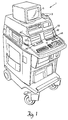
- FIG. 1 is a perspective view of the medical ultrasound imaging system featuring the partitioned menu control panel of this invention.
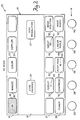
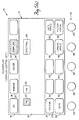
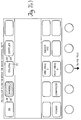
- FIG. 2 is a plan view of the control panel of this invention displaying the 2D mode menu.
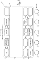
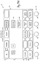
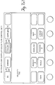
- FIG. 3 is a plan view of the control panel of FIG. 2 displaying the M Mode menu.
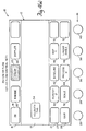
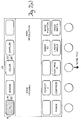
- FIG. 4(a) and FIG. 4(b) are plan views of the control panel of FIG. 2 displaying Color Flow mode menus.
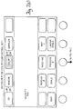
- FIG. 5(a) and FIG. 5(b) are plan views of the control panel of FIG. 2 displaying Doppler mode menus.
- FIG. 6 is a system state diagram for the ultrasound system of FIG. 1.
- FIG. 7(a) through FIG. 7(e) are plan views of the control panel of FIG. 2 displaying menu changes in response to ultrasound system mode selections.
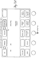
- FIG. 8 is a plan view of a second control panel of the invention displaying the non-imaging system control menu.
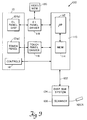
- FIG. 9 is a block diagram of a controller for implementing the ultrasound system control panel of FIG. 1.
- FIG. 1 there is shown a medical ultrasound imaging system 1 having an ultrasonic imaging probe 3 for imaging a patient, and a display 5 for displaying the ultrasound image generated by the system.
- Two menu driven control panels 10 and 10' provide an improved user interface to the ultrasound system according to the invention.
- the menu driven control panel 10 of the ultrasound imaging system 1 of FIG. 1 features a flat menu hierarchy to partition the ultrasound system controls into smaller control sets specific to each of the different system modes.
- the control sets are divided into menu items, with each menu item typically controlling one system function.
- Control panel 10 includes a flat electroluminescent touch panel 12 (EL panel) and soft controls 14 (FIG. 1) for displaying menu items to the user.
- the user touches a menu item displayed on the EL panel to select that menu item, and the ultrasound system responds accordingly.
- a row of soft controls 14, which are rotatable soft controls in the preferred embodiments described herein, is positioned below and adjacent to the EL panel. Each rotatable control operates according to a corresponding function displayed on the adjacent EL panel.
- the minimum control set menu displayed on the EL panel 12 is divided into three groups of controls: a control set selection group 16 located at the top of the EL panel, a functional control group 19 located at the center of the EL panel, and a rotatable control group 21 located at the bottom of the EL panel adjacent to the row of rotatable controls 14.
- the control set selection group 16 contains the control set entry points for each of the individual valid ultrasound modes, and remains available to the user regardless of the current operating mode of the system. Control set selection group 16 allows the user to select the 2D control set from menu item 18, the M-Mode control set from menu item 20, the COLOR control set from menu item 22, or the DOPPLER control set from menu item 24. If, for instance, a linear transducer is connected to the system and is active, M Mode is an invalid mode and therefore, menu item 20 will be empty.
- the menu item When the user selects a control set by touching the appropriate control set selection menu item, the menu item is highlighted, and the remainder of the EL panel below the control set selection group 16 is reformatted to display the selected control set.
- the selected control set may display as menu items only valid functions for the selected system mode.
- the 2D control group has been selected and menu item 18 is highlighted (shown as cross-hatching) indicating that the other groups of the EL panel display the 2D control set.
- the user activates more than one system mode simultaneously e.g., in a composite mode
- only the last selected control group is displayed and the activated system modes are indicated in the appropriate control set menu item. Composite modes are discussed in detail below.
- Functional control group 19 displays menu items offering the user various functions available in the selected control set.
- the 2D control set offers the user an on/off EDGE ENHANCE function, menu item 23, and an on/off HIGH RESOLUTION function, menu item 27. Again, the desired function is activated by touching the corresponding menu item.
- Rotatable control group 21 displays menu items indicating the function assigned or assignable to each of the rotatable controls 14 for the selected control set.
- the rotatable controls shown in FIG. 2, and discussed below, are for the 2D control set.
- Rotatable control 25 controls the ultrasound system transmit power as indicated by the POWER menu item 26 adjacent to the control.
- Rotatable control 28 has dual functionality and controls either image persistence as indicated by the PERSIST menu item 30 or image compression as indicated by the COMPRESS menu item 32.
- the user selects the function of control 28 by touching either PERSIST or COMPRESS.
- the selected menu item is highlighted.
- the menu item associated with a rotatable control may also display the state of the control relating to that menu item, e.g., PERSIST menu item 30 also shows that rotatable control 28 has previously selected persistence mode 2 indicated by numeral 34.
- Rotatable control 36 controls the 2D image post processing as indicated by the POST PROC menu item 44 adjacent to the control.
- letter 45 indicates the current post processing selection, e.g., post processing map B.
- Rotatable control 38 also has dual functionality and controls either the physiological trace (e.g., an ECG trace displayed along with the ultrasound image) sweep rate as indicated by the SWEEP menu item 46 or linear angle as indicated by the LINEAR ANGLE menu item 48.
- the SWEEP menu item is only displayed when the physiological measurement devices are configured to be operational, and the LINEAR ANGLE menu item is only displayed when a linear imaging transducer is active.
- the user selects the function of control 38 by touching either SWEEP or LINEAR ANGLE, and the selected menu item is highlighted.
- the SWEEP menu item also displays the current physiological trace sweep rate indicated by numeral 47, e.g., here indicating 50 mm/sec..
- Rotatable control 40 also has dual functionality and controls either the image position as indicated by the IMAGE POSITION menu item 50 or image width as indicated by the IMAGE WIDTH menu item 52.
- the IMAGE POSITION menu item is only displayed when the 2D image is reduced in size.
- EL panel 12 displays the M mode control set activated by selecting the M MODE menu item 20 of the control set selection group 16.
- the M MODE menu item 20 is illuminated (shown by cross-hatching) to indicate that the EL panel menu is displaying the M mode control set.
- the M mode control set has fewer menu items than the 2D control set of FIG. 2.
- functional control group 19 contains no menu items.
- Rotatable control 25 retains it control over the ultrasound system transmit power as indicated by POWER menu item 26.
- Rotatable control 28 retains control over image compression as indicated by COMPRESS menu item 32, but no longer optionally controls persistence, i.e., menu item 30 is now empty.
- Rotatabie control 36 now has dual functionality with M mode preprocessing now available on PRE PROC menu item 42 in addition to image postprocessing available on POST PROC menu item 44.
- Rotatable control 38 controls the M mode trace sweep rate (the physiological trace sweep rate is constrained to be the same as the M mode trace sweep rate in M mode) as indicated by SWEEP menu item 46, but no longer optionally controls the linear angle, i.e., menu item 48 is empty.
- Rotatable control 40 has no function in the M mode control set.
- POST PROC is set to B in the 2D and A in the M mode, as indicated by letter 45 of the POST PROC menu item 44 of FIGS. 1 and 2, respectively.
- the physiological trace sweep rate is set to 50 mm/sec in the 2D mode
- the M mode sweep rate is set to 100 mm/sec, as indicated by numeral 47 of SWEEP menu item 46 of FIGS. 1 and 2, respectively.
- EL panel 12 displays the color flow imaging mode control set activated by selecting the COLOR menu item 22 of the control set selection group 16.
- the COLOR menu item 22 is illuminated (shown by cross-hatching) to indicate that the EL panel menu is displaying the color flow imaging control set.
- Functional control group 19 of the color flow imaging control set features a velocity tag function indicated by VELOCITY TAG menu item 54.
- the functions of the rotatable controls have also been redefined.
- Rotatable control 25 now controls color flow gain as indicated by GAIN menu item 26.
- Rotatable control 28 now optionally controls either color flow persistence as indicated by PERSIST menu item 30 or color scale as indicated by SCALE menu item 32.
- Rotatable control 36 now optionally controls color flow baseline as indicated by BASELINE menu item 42 or color flow process as indicated by PROCESS menu item 44.
- Rotatable control 38 now optionally controls either the color map selection as indicated by MAP menu item 46 or linear sector angle indicated by LINEAR ANGLE menu item 48. Again, the linear probe must be active to display LINEAR ANGLE menu item 48.
- Rotatable control 40 has no function in this control set.
- the selection of VELOCITY TAG menu item 54 highlights the menu item (shown by cross-hatching) and causes the TAG 1 menu item 56 and TAG 2 menu item 58 to appear in the functional control group 19, and the TAG POSITION menu item 27 to appear over rotatable control 25.
- the TAG 1 and TAG 2 menu items operate in tandem such that exactly one of the TAG 1 or TAG 2 items is always selected.
- velocity tag 1 is selected as indicated by the highlighted TAG 1 menu item 56.
- Rotatable control 25 now optionally controls the position of color tag 1 as indicated by the TAG POSITION menu item 27 or the color gain indicated by the GAIN menu item 26. Rotatable control 25 would optionally control the position of color tag 2 if the TAG 2 menu item 58 were selected.
- EL panel 12 displays the Doppler imaging mode control set activated by selecting the DOPPLER menu item 24 of the control set selection group 16.
- the DOPPLER menu item 24 is highlighted (shown by cross-hatching) to indicate that the EL panel menu is displaying the Doppler imaging mode control set.
- Functional control group 19 of the Doppler imaging control set features a pulsed wave Doppler function indicated by the PW menu item 60, a continuous wave Doppler function indicated by the CW menu item 62, and a spectral display function indicated by the SPECTRAL menu item 64.
- the PW menu item 60 and the CW menu item 62 operate in tandem such that exactly one of the PW or CW menu item is selected at any one time, i.e., the user may select either the pulsed wave or the continuous wave Doppler mode, but not both.
- FIG. 5(a) shows PW as the selected mode as indicated by the highlighted PW menu item 60, and SPECTRAL menu item 64 as unselected.
- Rotatable control 25 optionally controls either the Doppler audio volume as indicated by VOLUME menu item 27 or the Doppler gain as indicated by GAIN menu item 26.
- the VOLUME menu item is displayed when the Doppler audio signal has been activated by other system controls. Separate VOLUME and GAIN control values are retained by the system for the PW and CW modes.
- Rotatable control 38 again controls the linear angle as indicated by LINEAR ANGLE menu item 48, but is only displayed when a linear probe is connected to the system.
- Rotatable control 40 optionally controls the Doppler gate angle as indicated by the GATE ANGLE menu item 50 or the variable low frequency cutoff of the Doppler audio filter as indicated by the FILTER menu item 52.
- FILTER menu item 52 also displays the current filter setting, here shown as 400 Hz.
- the selection of the SPECTRAL menu item 64 highlights the menu item (shown by cross-hatching) and causes the SPECTRAL INVERT menu item 66 to appear in the functional control group 19. Selection of the SPECTRAL menu item also causes several new rotatable control menu items to appear.
- Rotatable control 28 now controls the scale of the displayed Doppler spectrum as indicated by the SCALE menu item 32.
- Rotatable control 36 now optionally controls either the baseline of the displayed Doppler spectrum as indicated by the BASELINE menu item 42 or the Doppler spectral processing as indicated by the PROCESS menu item 44.
- Rotatable control 38 now optionally controls either the spectral sweep rate as indicated by the SWEEP menu control 46, or the linear angle as indicated by the LINEAR ANGLE menu item 48.
- FIG. 6 there is shown a table of ultrasound system states describing the various ultrasound system modalities available.
- the left hand column shows the current state of the system
- the top row of the table shows the input to the system, i.e., the menu item selection made by the user
- the interior of the table show the system state that results from the system input.
- the system inputs listed as 2D, MMODE, COLOR, and DOPPLER correspond to the control set selection group 16 (FIG. 2) menu items 18, 20, 22, and 24, respectively.
- the PW, CW, and SPECTRAL system inputs correspond to the DOPPLER control set functional control group 19 (FIGS.
- the TRIGGER system input is a hard-wired system control not displayed on the EL panel menu, and when activated causes the ultrasound image to be formed only upon the occurrence of some external event such as the R wave of an ECG trace.
- the image remains frozen during the period between triggers. Furthermore, the image is also frozen if the system is put into a Doppler search state, which allows the user to listen to high quality Doppler audio while positioning the Doppler gate in PW or the line cursor in CW.
- the system may always be returned to the nominal 2D imaging mode by selecting the 2D system input, i.e., the 2D menu item 18 (FIG. 2).
- the 2D menu item 18 FIG. 2
- the system enters the 2D/M MODE(MM) state and the EL panel appears as shown in FIG. 3.
- the system When the system is in the 2D mode and COLOR menu item 22 is selected, the system enters the 2D/COLOR (CF) state and the EL panel appears as shown in FIG. 4(a).
- the system When the system is in the 2D mode and the DOPPLER menu item 24 is selected, the system enters the 2D(Triggered)/PW DOPPLER-AUDIO (PWA) state, and the EL panel appears as shown in FIG. 5(a).
- PWA DOPPLER mode
- the user may enter the PW search mode (PWx), the PW spectral mode (PWS), the CW search mode (CWx), or the CW spectral mode (CWS), by choosing the appropriate system inputs according to the state table.
- the M MODE, COLOR and DOPPLER system inputs also operate to toggle the system out of the corresponding mode. For instance, if the system is in the 2D/MM state and the M MODE menu item 20 (FIG. 3) is selected, the system will return to the 2D state. Similarly, if the system is in the 2D/CF state and the COLOR menu item 22 (FIG. 4(a)) is selected, the system will return to the 2D state. If the system is in any 2D/PW or 2D/CW Doppler state and the DOPPLER menu item (FIG. 5(a)) is selected, the system will return to the 2D state.
- the system When the system is in the 2D/MM state and COLOR menu item 22 (FIG. 3) is selected, the system enters the 2D/CF/MM composite mode state and the EL panel displays the color flow control set of FIG. 4(a).
- the EL panel would display the M mode control set of FIG. 3 if the system were first put into the 2D/CF state and then M MODE was selected to put the system in the 2D/CF/MM composite state. If the system is in the 2D/CF/MM state and DOPPLER is selected, the system enters the 2D/CF/PWx composite state and the EL panel appears as shown in FIG. 5(a).
- the PWx Doppler mode has replace the M Mode since simultaneous Doppler and M Mode are not allowed by the system.
- FIGS. 6(a) through 6(e) An example of the EL panel menu response to changing system states is shown by FIGS. 6(a) through 6(e).
- the nominal 2D system state is reflected by the EL panel menu of FIG. 7(a) which shows the 2D control set of FIG. 2.
- M MODE menu item 20 The user then selects M MODE menu item 20.
- the system enters the 2D/CF/MM composite mode and the EL panel responds as shown in FIG. 7(c) by displaying the M Mode control set of FIG. 3.
- An asterisk 70 is displayed in the COLOR menu item 22 to indicate that color flow mode is still active although the M mode control set is currently displayed.
- the color flow control set is available to the user, without changing the system state, by selecting the COLOR* menu item 22.
- the user By selecting the DOPPLER menu item 24 the user then causes the system to enter the 2D/CF/PWx composite color flow Doppler mode and the EL panel changes as shown in FIG. 7(d) to display the Doppler control set of FIG. 5(a). As discussed above, the Doppler mode has replaced M Mode. The color flow mode remains active as indicated by the asterisk 70 displayed in the COLOR menu item 22.
- the user By selecting the COLOR* menu item 22 the user causes the EL panel to change as shown in FIG. 7(e) to display the color flow control set of FIG. 4(a).
- the system remains in the 2D/CF/PWx color flow Doppler mode, i.e., the displayed control set changes from the Doppler control set of FIG. 7(d) to the color flow control set of FIG. 7(e) but the system state does not change.
- An asterisk 72 is now displayed in the DOPPLER menu item 24 to indicate that the Doppler mode is still active although the color flow control set is currently shown in the EL panel.
- the Doppler control set may be redisplayed on the EL panel without changing the system state by selecting the DOPPLER* menu item 24.
- EL panel 12' may be the same EL panel 12 of FIG. 2 with the non-imaging related functions displayed in place of the imaging function, but preferably EL panel 12' is a separate panel mounted adjacent to EL panel 12 so that the user may have imaging and non-imaging controls simultaneously available. It will be appreciated by those skilled in the art that a single EL panel large enough to display both the imaging and non-imaging control sets may be used in place of two separate panels.
- the same flat menu hierarchy is employed with the non-imaging controls.
- the control set selection group 16' displays menu items of available control sets to the user, and functional control group 19' displays menu items available in the selected control set.
- the VCR CONTROLS menu item 100 has been selected, and the functional control group 19' displays the familiar VCR control menu items.
- Control panel 10 is coupled to a keyboard controller 110 which includes a microprocessor portion 112 that responds to menu handler software instructions stored in a memory 114.
- EL touch panel 12 (FIG. 1) is shown as two portions, touch panel 12(a) and EL panel display 12(b).
- the touch panel 12(a) is connected to the controller 110 through a touch panel driver circuit 116 which allows the controller to communicate with the touch panel, i.e., enable the touch panel to respond to various input and communicate received input to the controller.
- the EL panel display 12(b) is connected to the controller through an EL panel video driver 118 for displaying menu items on the panel in response to the keyboard controller.
- a video memory 120 stores the EL panel menu items in video format.
- a data communication channel 122 is connected from the keyboard controller 112 to the rest of the ultrasound system including the display subsystem 124 and scanner subsystem 126.
- the keyboard controller issues commands to the display and scanner subsystems to cause the system to enter various modes in response to user input to the control panel.
Abstract
Description
- Medical ultrasound imaging systems have evolved into complex instruments offering a wide variety of imaging modalities including two dimensional imaging mode (2D) which may have a sector or linear format, M Mode (MM), color Flow (COLOR), and Doppler (DOPPLER) imaging. Each modality requires a set of user controls unique to that modality. Not only is each mode operational independent of the other modes, but they may also be combined into a variety of composite modes. These composite modes include 2D/MM, 2D/COLOR, 2D/COLOR/MM, 2D/DOPPER and 2D/COLOR/DOPPLER. The complexity of the user controls required to operate the system in a composite mode is increased substantially since the user controls for each mode making up the composite mode must be readily available to the user. The situation is further complicated since some controls must be dedicated to system functions which are independent of the selected modality, e.g., VCR and hard copy controls.
- Medical ultrasound imaging systems are typically used to image patients in real time. Thus, the user must be able to operate the system controls efficiently. As the complexity and functionality of the ultrasound system increases, traditional hard-wired controls dedicated to each function produce more crowded control panels which are more difficult for the user to operate in real time. A control panel for an ultrasound system having a dedicated control for each available function would require over 100 controls.
- Ultrasound system control panels have been developed which minimize the control set available to the user at any one time, dependent on the selected ultrasound mode, to reduce control complexity. One such minimum control set approach uses programmable "soft keys" whose functions change dependent upon the selected mode. A new function may be assigned to each soft key as the mode change and displayed on a display device.
- Hierarchical menus, such as "pull-down" menus, have also been used to minimize the control set available to the user. Each menu is displayed on a display device and typically offers a list of available menu items related to a particular mode or function from which the user selects one item. This selection either produces the desired function or causes another lower level menu to be displayed which offers more menu items related to the first selected item. The selection process is repeated until the desired ultrasound system function is selected. The user may need to go through several menu layers to reach the desired function. From there the user may need to back track through several menu layers to reach another desired function.
- The present invention provides a control panel for a medical ultrasound imaging system which offers the user the control simplicity of a reduced set of control functions for each ultrasound mode (control set) while allowing the user instant access to any control set regardless of the current system mode.
- In general, in one aspect, the invention features an ultrasound imaging system having a control panel which includes menu items divided into system mode menu items for selecting a system mode, and control set menu items for selecting functions corresponding to a selected system mode menu item. Menu items are displayed on a control panel display so that the control set menu items displayed correspond to the selected system mode. The system mode menu items are always available for selection independent of which control set is being displayed.
- Preferred embodiments include an electroluminescent panel for displaying menu items. The electroluminescent panel may be a touch panel and the user selects a menu item by touching the item on the panel. Other embodiments include controls located on the control panel adjacent to the display and displayed menu items which define the functions of the controls. The controls include rotatable control knobs. More than one menu item may define functions available for a control, and one of the menu items is selected to define the current function of the control.
- Other preferred embodiments include more then one system mode being activated at the same time by selecting each desired system mode in sequence from the system mode menu items. Control set menu items are displayed which correspond to the last selected system mode. The system modes include 2D, M mode, Color flow, and Doppler imaging.
- Yet other preferred embodiments include another display for displaying menu items for controlling non-imaging functions.
- In general, in another aspect, the invention features a method for controlling an ultrasound system including displaying system mode menu items on a display, selecting a system mode from the system mode menu items, and displaying the control set menu items of the selected system mode in addition to the system mode menu items.
- Thus, the present invention has the advantages of offering the user of the system mode specific control sets without hiding the control sets under layers of menus, which would otherwise mask system functionality. Modes which may be activated simultaneously are easily activated from any current system mode, and the control set for each activated mode is easily accessible. The touch panel of this invention offers the user instant menu choice selection by touching the menu item itself, which enhances system controllability during real time medical ultrasound exams.
- The foregoing and other objects, features and advantages of the invention will be apparent from the following more particular description of preferred embodiments of the invention, as illustrated in the accompanying drawings in which like reference characters refer to the same parts throughout the different views. The drawings are not necessarily to scale, emphasis instead being placed upon illustrating the principles of the invention.
- FIG. 1 is a perspective view of the medical ultrasound imaging system featuring the partitioned menu control panel of this invention.
- FIG. 2 is a plan view of the control panel of this invention displaying the 2D mode menu.
- FIG. 3 is a plan view of the control panel of FIG. 2 displaying the M Mode menu.
- FIG. 4(a) and FIG. 4(b) are plan views of the control panel of FIG. 2 displaying Color Flow mode menus.
- FIG. 5(a) and FIG. 5(b) are plan views of the control panel of FIG. 2 displaying Doppler mode menus.
- FIG. 6 is a system state diagram for the ultrasound system of FIG. 1.
- FIG. 7(a) through FIG. 7(e) are plan views of the control panel of FIG. 2 displaying menu changes in response to ultrasound system mode selections.
- FIG. 8 is a plan view of a second control panel of the invention displaying the non-imaging system control menu.
- FIG. 9 is a block diagram of a controller for implementing the ultrasound system control panel of FIG. 1.
- Referring to FIG. 1, there is shown a medical
ultrasound imaging system 1 having anultrasonic imaging probe 3 for imaging a patient, and adisplay 5 for displaying the ultrasound image generated by the system. Two menu drivencontrol panels 10 and 10' provide an improved user interface to the ultrasound system according to the invention. - Referring to FIG. 2, the menu driven
control panel 10 of theultrasound imaging system 1 of FIG. 1 features a flat menu hierarchy to partition the ultrasound system controls into smaller control sets specific to each of the different system modes. The control sets are divided into menu items, with each menu item typically controlling one system function.Control panel 10 includes a flat electroluminescent touch panel 12 (EL panel) and soft controls 14 (FIG. 1) for displaying menu items to the user. The user touches a menu item displayed on the EL panel to select that menu item, and the ultrasound system responds accordingly. A row ofsoft controls 14, which are rotatable soft controls in the preferred embodiments described herein, is positioned below and adjacent to the EL panel. Each rotatable control operates according to a corresponding function displayed on the adjacent EL panel. - The minimum control set menu displayed on the
EL panel 12 is divided into three groups of controls: a controlset selection group 16 located at the top of the EL panel, afunctional control group 19 located at the center of the EL panel, and arotatable control group 21 located at the bottom of the EL panel adjacent to the row ofrotatable controls 14. - The control set
selection group 16 contains the control set entry points for each of the individual valid ultrasound modes, and remains available to the user regardless of the current operating mode of the system. Controlset selection group 16 allows the user to select the 2D control set frommenu item 18, the M-Mode control set frommenu item 20, the COLOR control set frommenu item 22, or the DOPPLER control set frommenu item 24. If, for instance, a linear transducer is connected to the system and is active, M Mode is an invalid mode and therefore,menu item 20 will be empty. - When the user selects a control set by touching the appropriate control set selection menu item, the menu item is highlighted, and the remainder of the EL panel below the control set
selection group 16 is reformatted to display the selected control set. The selected control set may display as menu items only valid functions for the selected system mode. Here, for instance, the 2D control group has been selected andmenu item 18 is highlighted (shown as cross-hatching) indicating that the other groups of the EL panel display the 2D control set. When the user activates more than one system mode simultaneously, e.g., in a composite mode, only the last selected control group is displayed and the activated system modes are indicated in the appropriate control set menu item. Composite modes are discussed in detail below. -
Functional control group 19 displays menu items offering the user various functions available in the selected control set. Here, the 2D control set offers the user an on/off EDGE ENHANCE function,menu item 23, and an on/off HIGH RESOLUTION function,menu item 27. Again, the desired function is activated by touching the corresponding menu item. -
Rotatable control group 21 displays menu items indicating the function assigned or assignable to each of the rotatable controls 14 for the selected control set. The rotatable controls shown in FIG. 2, and discussed below, are for the 2D control set. -
Rotatable control 25 controls the ultrasound system transmit power as indicated by thePOWER menu item 26 adjacent to the control. -
Rotatable control 28 has dual functionality and controls either image persistence as indicated by the PERSISTmenu item 30 or image compression as indicated by theCOMPRESS menu item 32. The user selects the function ofcontrol 28 by touching either PERSIST or COMPRESS. The selected menu item is highlighted. Further, the menu item associated with a rotatable control may also display the state of the control relating to that menu item, e.g., PERSISTmenu item 30 also shows thatrotatable control 28 has previously selectedpersistence mode 2 indicated bynumeral 34. -
Rotatable control 36 controls the 2D image post processing as indicated by the POSTPROC menu item 44 adjacent to the control. Here,letter 45 indicates the current post processing selection, e.g., post processing map B. -
Rotatable control 38 also has dual functionality and controls either the physiological trace (e.g., an ECG trace displayed along with the ultrasound image) sweep rate as indicated by theSWEEP menu item 46 or linear angle as indicated by the LINEARANGLE menu item 48. The SWEEP menu item is only displayed when the physiological measurement devices are configured to be operational, and the LINEAR ANGLE menu item is only displayed when a linear imaging transducer is active. The user selects the function ofcontrol 38 by touching either SWEEP or LINEAR ANGLE, and the selected menu item is highlighted. The SWEEP menu item also displays the current physiological trace sweep rate indicated bynumeral 47, e.g., here indicating 50 mm/sec.. -
Rotatable control 40 also has dual functionality and controls either the image position as indicated by the IMAGEPOSITION menu item 50 or image width as indicated by the IMAGEWIDTH menu item 52. The IMAGE POSITION menu item is only displayed when the 2D image is reduced in size. - Referring to FIG. 3,
EL panel 12 displays the M mode control set activated by selecting the MMODE menu item 20 of the control setselection group 16. The MMODE menu item 20 is illuminated (shown by cross-hatching) to indicate that the EL panel menu is displaying the M mode control set. - The M mode control set has fewer menu items than the 2D control set of FIG. 2. For instance,
functional control group 19 contains no menu items.Rotatable control 25 retains it control over the ultrasound system transmit power as indicated byPOWER menu item 26.Rotatable control 28 retains control over image compression as indicated byCOMPRESS menu item 32, but no longer optionally controls persistence, i.e.,menu item 30 is now empty.Rotatabie control 36 now has dual functionality with M mode preprocessing now available on PREPROC menu item 42 in addition to image postprocessing available on POSTPROC menu item 44.Rotatable control 38 controls the M mode trace sweep rate (the physiological trace sweep rate is constrained to be the same as the M mode trace sweep rate in M mode) as indicated bySWEEP menu item 46, but no longer optionally controls the linear angle, i.e.,menu item 48 is empty.Rotatable control 40 has no function in the M mode control set. - It should be noted that some controls may retain the last value assigned to them in a particular mode and restore those values when the mode is re-entered. For instance POST PROC is set to B in the 2D and A in the M mode, as indicated by
letter 45 of the POSTPROC menu item 44 of FIGS. 1 and 2, respectively. Similarly, the physiological trace sweep rate is set to 50 mm/sec in the 2D mode, and the M mode sweep rate is set to 100 mm/sec, as indicated bynumeral 47 ofSWEEP menu item 46 of FIGS. 1 and 2, respectively. - Referring to FIG. 4(a),
EL panel 12 displays the color flow imaging mode control set activated by selecting theCOLOR menu item 22 of the control setselection group 16. TheCOLOR menu item 22 is illuminated (shown by cross-hatching) to indicate that the EL panel menu is displaying the color flow imaging control set. -
Functional control group 19 of the color flow imaging control set features a velocity tag function indicated by VELOCITYTAG menu item 54. The functions of the rotatable controls have also been redefined.Rotatable control 25 now controls color flow gain as indicated byGAIN menu item 26.Rotatable control 28 now optionally controls either color flow persistence as indicated by PERSISTmenu item 30 or color scale as indicated bySCALE menu item 32.Rotatable control 36 now optionally controls color flow baseline as indicated byBASELINE menu item 42 or color flow process as indicated byPROCESS menu item 44.Rotatable control 38 now optionally controls either the color map selection as indicated byMAP menu item 46 or linear sector angle indicated by LINEARANGLE menu item 48. Again, the linear probe must be active to display LINEARANGLE menu item 48.Rotatable control 40 has no function in this control set. - Referring to FIG. 4(b), the selection of VELOCITY
TAG menu item 54 highlights the menu item (shown by cross-hatching) and causes theTAG 1menu item 56 andTAG 2menu item 58 to appear in thefunctional control group 19, and the TAGPOSITION menu item 27 to appear overrotatable control 25. TheTAG 1 andTAG 2 menu items operate in tandem such that exactly one of theTAG 1 orTAG 2 items is always selected. As shown here,velocity tag 1 is selected as indicated by the highlightedTAG 1menu item 56.Rotatable control 25 now optionally controls the position ofcolor tag 1 as indicated by the TAGPOSITION menu item 27 or the color gain indicated by theGAIN menu item 26.Rotatable control 25 would optionally control the position ofcolor tag 2 if theTAG 2menu item 58 were selected. - Referring to FIG. 5(a),
EL panel 12 displays the Doppler imaging mode control set activated by selecting theDOPPLER menu item 24 of the control setselection group 16. TheDOPPLER menu item 24 is highlighted (shown by cross-hatching) to indicate that the EL panel menu is displaying the Doppler imaging mode control set. -
Functional control group 19 of the Doppler imaging control set features a pulsed wave Doppler function indicated by thePW menu item 60, a continuous wave Doppler function indicated by theCW menu item 62, and a spectral display function indicated by theSPECTRAL menu item 64. ThePW menu item 60 and theCW menu item 62 operate in tandem such that exactly one of the PW or CW menu item is selected at any one time, i.e., the user may select either the pulsed wave or the continuous wave Doppler mode, but not both. FIG. 5(a) shows PW as the selected mode as indicated by the highlightedPW menu item 60, andSPECTRAL menu item 64 as unselected. -
Rotatable control 25 optionally controls either the Doppler audio volume as indicated byVOLUME menu item 27 or the Doppler gain as indicated byGAIN menu item 26. The VOLUME menu item is displayed when the Doppler audio signal has been activated by other system controls. Separate VOLUME and GAIN control values are retained by the system for the PW and CW modes.Rotatable control 38 again controls the linear angle as indicated by LINEARANGLE menu item 48, but is only displayed when a linear probe is connected to the system.Rotatable control 40 optionally controls the Doppler gate angle as indicated by the GATEANGLE menu item 50 or the variable low frequency cutoff of the Doppler audio filter as indicated by theFILTER menu item 52.FILTER menu item 52 also displays the current filter setting, here shown as 400 Hz. - Referring to FIG. 5(b), the selection of the
SPECTRAL menu item 64 highlights the menu item (shown by cross-hatching) and causes the SPECTRALINVERT menu item 66 to appear in thefunctional control group 19. Selection of the SPECTRAL menu item also causes several new rotatable control menu items to appear.Rotatable control 28 now controls the scale of the displayed Doppler spectrum as indicated by theSCALE menu item 32.Rotatable control 36 now optionally controls either the baseline of the displayed Doppler spectrum as indicated by theBASELINE menu item 42 or the Doppler spectral processing as indicated by thePROCESS menu item 44.Rotatable control 38 now optionally controls either the spectral sweep rate as indicated by theSWEEP menu control 46, or the linear angle as indicated by the LINEARANGLE menu item 48. - Referring to FIG. 6 there is shown a table of ultrasound system states describing the various ultrasound system modalities available. The left hand column shows the current state of the system, the top row of the table shows the input to the system, i.e., the menu item selection made by the user, and the interior of the table show the system state that results from the system input. The system inputs listed as 2D, MMODE, COLOR, and DOPPLER correspond to the control set selection group 16 (FIG. 2)
menu items menu items - As shown in the system state diagram, the system may always be returned to the nominal 2D imaging mode by selecting the 2D system input, i.e., the 2D menu item 18 (FIG. 2). When the system is in the 2D mode and the M MODE menu item 20 (FIG. 2) is selected, the system enters the 2D/M MODE(MM) state and the EL panel appears as shown in FIG. 3. When the system is in the 2D mode and
COLOR menu item 22 is selected, the system enters the 2D/COLOR (CF) state and the EL panel appears as shown in FIG. 4(a). When the system is in the 2D mode and theDOPPLER menu item 24 is selected, the system enters the 2D(Triggered)/PW DOPPLER-AUDIO (PWA) state, and the EL panel appears as shown in FIG. 5(a). Once in the DOPPLER mode (PWA) the user may enter the PW search mode (PWx), the PW spectral mode (PWS), the CW search mode (CWx), or the CW spectral mode (CWS), by choosing the appropriate system inputs according to the state table. - The M MODE, COLOR and DOPPLER system inputs also operate to toggle the system out of the corresponding mode. For instance, if the system is in the 2D/MM state and the M MODE menu item 20 (FIG. 3) is selected, the system will return to the 2D state. Similarly, if the system is in the 2D/CF state and the COLOR menu item 22 (FIG. 4(a)) is selected, the system will return to the 2D state. If the system is in any 2D/PW or 2D/CW Doppler state and the DOPPLER menu item (FIG. 5(a)) is selected, the system will return to the 2D state.
- When the system is in the 2D/MM state and COLOR menu item 22 (FIG. 3) is selected, the system enters the 2D/CF/MM composite mode state and the EL panel displays the color flow control set of FIG. 4(a). The EL panel would display the M mode control set of FIG. 3 if the system were first put into the 2D/CF state and then M MODE was selected to put the system in the 2D/CF/MM composite state. If the system is in the 2D/CF/MM state and DOPPLER is selected, the system enters the 2D/CF/PWx composite state and the EL panel appears as shown in FIG. 5(a). The PWx Doppler mode has replace the M Mode since simultaneous Doppler and M Mode are not allowed by the system.
- An example of the EL panel menu response to changing system states is shown by FIGS. 6(a) through 6(e). The nominal 2D system state is reflected by the EL panel menu of FIG. 7(a) which shows the 2D control set of FIG. 2.
- Upon selection of
COLOR menu item 22 by the user, the system enters the 2D/CF mode and the EL panel menu transforms to that of FIG. 7(b) which shows the color flow control set of FIG. 4(a). - The user then selects M
MODE menu item 20. The system enters the 2D/CF/MM composite mode and the EL panel responds as shown in FIG. 7(c) by displaying the M Mode control set of FIG. 3. Anasterisk 70 is displayed in theCOLOR menu item 22 to indicate that color flow mode is still active although the M mode control set is currently displayed. The color flow control set is available to the user, without changing the system state, by selecting the COLOR*menu item 22. - By selecting the
DOPPLER menu item 24 the user then causes the system to enter the 2D/CF/PWx composite color flow Doppler mode and the EL panel changes as shown in FIG. 7(d) to display the Doppler control set of FIG. 5(a). As discussed above, the Doppler mode has replaced M Mode. The color flow mode remains active as indicated by theasterisk 70 displayed in theCOLOR menu item 22. - By selecting the COLOR*
menu item 22 the user causes the EL panel to change as shown in FIG. 7(e) to display the color flow control set of FIG. 4(a). The system remains in the 2D/CF/PWx color flow Doppler mode, i.e., the displayed control set changes from the Doppler control set of FIG. 7(d) to the color flow control set of FIG. 7(e) but the system state does not change. Anasterisk 72 is now displayed in theDOPPLER menu item 24 to indicate that the Doppler mode is still active although the color flow control set is currently shown in the EL panel. The Doppler control set may be redisplayed on the EL panel without changing the system state by selecting the DOPPLER*menu item 24. - Referring to FIG. 8, there is shown another example of another EL panel control panel 10' for controlling the non-imaging related functions of a medical ultrasound imaging system. EL panel 12' may be the
same EL panel 12 of FIG. 2 with the non-imaging related functions displayed in place of the imaging function, but preferably EL panel 12' is a separate panel mounted adjacent toEL panel 12 so that the user may have imaging and non-imaging controls simultaneously available. It will be appreciated by those skilled in the art that a single EL panel large enough to display both the imaging and non-imaging control sets may be used in place of two separate panels. - The same flat menu hierarchy is employed with the non-imaging controls. The control set selection group 16' displays menu items of available control sets to the user, and functional control group 19' displays menu items available in the selected control set. Here, for instance, the VCR
CONTROLS menu item 100 has been selected, and the functional control group 19' displays the familiar VCR control menu items. - Referring to FIG. 9, there is shown a block diagram of a
controller 100 for implementing the ultrasound system control panel of this invention.Control panel 10 is coupled to akeyboard controller 110 which includes amicroprocessor portion 112 that responds to menu handler software instructions stored in amemory 114. - EL touch panel 12 (FIG. 1) is shown as two portions, touch panel 12(a) and EL panel display 12(b). The touch panel 12(a) is connected to the
controller 110 through a touchpanel driver circuit 116 which allows the controller to communicate with the touch panel, i.e., enable the touch panel to respond to various input and communicate received input to the controller. The EL panel display 12(b) is connected to the controller through an ELpanel video driver 118 for displaying menu items on the panel in response to the keyboard controller. Avideo memory 120 stores the EL panel menu items in video format. - A
data communication channel 122 is connected from thekeyboard controller 112 to the rest of the ultrasound system including thedisplay subsystem 124 andscanner subsystem 126. The keyboard controller issues commands to the display and scanner subsystems to cause the system to enter various modes in response to user input to the control panel. - While this invention has been particularly shown and described with reference to preferred embodiments thereof, it will be understood by those skilled in the art that various changes in form and details may be made therein without departing from the spirit and scope of the invention as defined by the appended claims.
Claims (10)
- An ultrasound imaging system (1) comprising:
a control panel means (10) comprising a plurality of menu items divided into a first group (16) of menu items and a second group (19, 21) of menu items, said first group (16) of menu items for selecting from a plurality of system modes;
a display means (12) for displaying said second group (19, 21) of menu items defining a control set of a plurality of system functions corresponding to a selected system mode;
means for selecting each system mode from the first group (16) of menu items and for providing the second group of menu items (19, 21) to correspond to the selected system mode control set, wherein unselected menu items of the first group (16) of system mode menu items are always available for selection independent of which control set the second group (19, 21) of menu items is displayed. - The ultrasound system (1) of Claim 1 wherein the display means (12) comprises an electroluminescent panel.
- The ultrasound system (1) of Claim 1 wherein the display means (12) comprises an electroluminescent touch panel, and each menu item function (16, 19, 21) is selectable by touching the corresponding menu item on the display means.
- The ultrasound system (1) of Claim 1, 2, or 3 further comprising
a plurality of control means (14) disposed on the control panel means (10) adjacent to the display means (12) and at least one menu item (21) is displayable for defining the function of at least one of said plurality of control means (14). - The ultrasound system (1) of Claim 4 wherein one of said menu items displays the functions available for the control and one of the plurality of functions is selected to define the current function of the control.
- The ultrasound system (1) of Claim 4 or 5 wherein the control means (14) comprise at least one rotatable control.
- The ultrasound system (1) of Claim 1, 2, 3, 4, 5, or 6 wherein one or more system modes may be activated simultaneously by selecting each desired system mode in sequence from the first group (16) of menu items, each system mode selection causing the second group (19, 21) of menu items to correspond to a previously selected system mode control set.
- The ultrasound system (1) of Claim 1, 2, 3, 4, 5, 6, or 7 wherein selecting a menu item from the second group (19, 21) of menu items may display additional system function menu items in the second group.
- The ultrasound system (1) of Claim 1, 2, 3, 4, 5, 6, 7 or 8 further comprising
a second display means (12') for displaying another second group of menu items defining a control set of a plurality of system functions corresponding to the selected system mode. - The ultrasound system of Claim 9 wherein
the first display means (12) displays system mode control sets for controlling the imaging aspects; and
the second display means (12') displays system mode control sets for controlling the non-imaging aspects of the system.
Applications Claiming Priority (2)
| Application Number | Priority Date | Filing Date | Title |
|---|---|---|---|
| US720149 | 1985-02-14 | ||
| US07/720,149 US5161535A (en) | 1991-06-24 | 1991-06-24 | Medical ultrasound imaging system having a partitioned menu |
Publications (2)
| Publication Number | Publication Date |
|---|---|
| EP0520338A2 true EP0520338A2 (en) | 1992-12-30 |
| EP0520338A3 EP0520338A3 (en) | 1994-03-30 |
Family
ID=24892844
Family Applications (1)
| Application Number | Title | Priority Date | Filing Date |
|---|---|---|---|
| EP19920110400 Ceased EP0520338A2 (en) | 1991-06-24 | 1992-06-19 | A medical ultrasound imaging system having a partitioned menu |
Country Status (3)
| Country | Link |
|---|---|
| US (1) | US5161535A (en) |
| EP (1) | EP0520338A2 (en) |
| JP (1) | JPH05220142A (en) |
Cited By (6)
| Publication number | Priority date | Publication date | Assignee | Title |
|---|---|---|---|---|
| EP0856283A1 (en) * | 1997-02-04 | 1998-08-05 | Medison Co., Ltd. | Ultrasonic diagnostic apparatus having a patient-use monitor |
| US6030344A (en) * | 1996-12-04 | 2000-02-29 | Acuson Corporation | Methods and apparatus for ultrasound image quantification |
| US6086539A (en) * | 1996-12-04 | 2000-07-11 | Acuson Corporation | Methods and apparatus for ultrasound image quantification |
| US8096943B2 (en) | 2006-12-04 | 2012-01-17 | University Of Washington Through Its Center For Commercialization | Flexible endoscope tip bending mechanism using optical fiber as compression member |
| US8824754B2 (en) | 2007-02-23 | 2014-09-02 | General Electric Company | Method and apparatus for generating variable resolution medical images |
| US9500944B2 (en) | 2007-03-02 | 2016-11-22 | General Electric Company | Method and apparatus for controlling ultrasound systems with physical controls |
Families Citing this family (65)
| Publication number | Priority date | Publication date | Assignee | Title |
|---|---|---|---|---|
| US5261824A (en) * | 1992-01-13 | 1993-11-16 | Ness Allan H | Sales promotion vehicle for demonstrating mobile electronic accessories |
| FR2689290B1 (en) * | 1992-03-26 | 1994-06-10 | Aerospatiale | MULTIMODE AND MULTIFUNCTIONAL COMMUNICATION METHOD AND DEVICE BETWEEN AN OPERATOR AND ONE OR MORE PROCESSORS. |
| US5394871A (en) * | 1992-06-25 | 1995-03-07 | Siemens Aktiengesellschaft | Medical diagnostics installation |
| US5315999A (en) * | 1993-04-21 | 1994-05-31 | Hewlett-Packard Company | Ultrasound imaging system having user preset modes |
| DE4406668C2 (en) * | 1993-04-27 | 1996-09-12 | Hewlett Packard Co | Method and device for operating a touch-sensitive display device |
| WO1995015521A2 (en) * | 1993-11-29 | 1995-06-08 | Perception, Inc. | Pc based ultrasound device with virtual control user interface |
| US6177923B1 (en) | 1994-12-30 | 2001-01-23 | Acuson Corporation | Imaging modality showing energy and velocity |
| DE69736549T2 (en) * | 1996-02-29 | 2007-08-23 | Acuson Corp., Mountain View | SYSTEM, METHOD AND CONVERTER FOR ORIENTING MULTIPLE ULTRASOUND IMAGES |
| US5963198A (en) * | 1996-12-23 | 1999-10-05 | Snap-On Technologies, Inc. | Low-cost user interface for refrigerant recycling machine |
| US6468212B1 (en) * | 1997-04-19 | 2002-10-22 | Adalberto Vara | User control interface for an ultrasound processor |
| US5973734A (en) | 1997-07-09 | 1999-10-26 | Flashpoint Technology, Inc. | Method and apparatus for correcting aspect ratio in a camera graphical user interface |
| US5919138A (en) * | 1997-08-22 | 1999-07-06 | Acuson Corporation | Ultrasound imaging system user interface |
| JP4006826B2 (en) * | 1998-04-28 | 2007-11-14 | 株式会社日立製作所 | Biological light measurement device |
| US6142940A (en) | 1998-10-06 | 2000-11-07 | Scimed Life Systems, Inc. | Control panel for intravascular ultrasonic imaging system |
| US6317141B1 (en) | 1998-12-31 | 2001-11-13 | Flashpoint Technology, Inc. | Method and apparatus for editing heterogeneous media objects in a digital imaging device |
| US6685645B1 (en) | 2001-10-20 | 2004-02-03 | Zonare Medical Systems, Inc. | Broad-beam imaging |
| US6733455B2 (en) * | 1999-08-20 | 2004-05-11 | Zonare Medical Systems, Inc. | System and method for adaptive clutter filtering in ultrasound color flow imaging |
| US20020173721A1 (en) * | 1999-08-20 | 2002-11-21 | Novasonics, Inc. | User interface for handheld imaging devices |
| US6599244B1 (en) | 1999-12-23 | 2003-07-29 | Siemens Medical Solutions, Usa, Inc. | Ultrasound system and method for direct manipulation interface |
| JP4737859B2 (en) * | 2001-03-29 | 2011-08-03 | 東芝医用システムエンジニアリング株式会社 | Ultrasonic diagnostic apparatus, X-ray CT apparatus, and display control program |
| JP4828731B2 (en) * | 2001-07-16 | 2011-11-30 | 日立アロカメディカル株式会社 | Ultrasonic diagnostic equipment |
| US20030045797A1 (en) * | 2001-08-28 | 2003-03-06 | Donald Christopher | Automatic optimization of doppler display parameters |
| KR100437104B1 (en) * | 2001-10-29 | 2004-06-23 | 삼성전자주식회사 | Controlling Method for Menu of electronic equipment |
| US20030153832A1 (en) * | 2002-01-22 | 2003-08-14 | Jona Zumeris | System and method for smart monitoring within a body |
| US6964640B2 (en) * | 2002-01-22 | 2005-11-15 | P M G Medica L I D | System and method for detection of motion |
| US7536644B2 (en) * | 2002-06-27 | 2009-05-19 | Siemens Medical Solutions Usa, Inc. | Method and system for facilitating selection of stored medical images |
| US7927275B2 (en) * | 2002-08-26 | 2011-04-19 | The Cleveland Clinic Foundation | System and method of aquiring blood-vessel data |
| US7904824B2 (en) * | 2002-12-10 | 2011-03-08 | Siemens Medical Solutions Usa, Inc. | Medical imaging programmable custom user interface system and method |
| US20060264746A1 (en) * | 2003-05-27 | 2006-11-23 | Koninklijke Philips Electronics N.V. | Diagnostic imaging system control with multiple control functions |
| US7594188B2 (en) * | 2003-08-21 | 2009-09-22 | Carl Zeiss Ag | Operating menu for a surgical microscope |
| US7052459B2 (en) * | 2003-09-10 | 2006-05-30 | General Electric Company | Method and apparatus for controlling ultrasound systems |
| US7336282B2 (en) * | 2003-09-11 | 2008-02-26 | Ricoh Company, Ltd. | System, recording medium and program for inputting operation condition of instrument |
| US6979295B2 (en) * | 2003-11-19 | 2005-12-27 | Ge Medical Systems Global Technology Company, Llc | Automatic color gain adjustments |
| US20050114175A1 (en) * | 2003-11-25 | 2005-05-26 | O'dea Paul J. | Method and apparatus for managing ultrasound examination information |
| US7526568B1 (en) * | 2004-02-20 | 2009-04-28 | Broadcast Pix, Inc. | Integrated live video production system |
| US7627386B2 (en) * | 2004-10-07 | 2009-12-01 | Zonaire Medical Systems, Inc. | Ultrasound imaging system parameter optimization via fuzzy logic |
| US8413271B2 (en) * | 2004-10-29 | 2013-04-09 | Stryker Corporation | Patient support apparatus |
| US7861334B2 (en) * | 2005-12-19 | 2011-01-04 | Stryker Corporation | Hospital bed |
| US9038217B2 (en) | 2005-12-19 | 2015-05-26 | Stryker Corporation | Patient support with improved control |
| US20060184029A1 (en) * | 2005-01-13 | 2006-08-17 | Ronen Haim | Ultrasound guiding system and method for vascular access and operation mode |
| US8002705B1 (en) | 2005-07-22 | 2011-08-23 | Zonaire Medical Systems, Inc. | Continuous transmit focusing method and apparatus for ultrasound imaging system |
| US8784318B1 (en) | 2005-07-22 | 2014-07-22 | Zonare Medical Systems, Inc. | Aberration correction using channel data in ultrasound imaging system |
| US20070129625A1 (en) * | 2005-11-21 | 2007-06-07 | Boston Scientific Scimed Systems, Inc. | Systems and methods for detecting the presence of abnormalities in a medical image |
| US11246776B2 (en) | 2005-12-19 | 2022-02-15 | Stryker Corporation | Patient support with improved control |
| US20070225590A1 (en) * | 2006-01-13 | 2007-09-27 | Boston Scientific Scimed, Inc. | Control panel for a medical imaging system |
| US9224145B1 (en) | 2006-08-30 | 2015-12-29 | Qurio Holdings, Inc. | Venue based digital rights using capture device with digital watermarking capability |
| US8286079B2 (en) * | 2006-09-19 | 2012-10-09 | Siemens Medical Solutions Usa, Inc. | Context aware user interface for medical diagnostic imaging, such as ultrasound imaging |
| US20080146922A1 (en) * | 2006-10-24 | 2008-06-19 | Zonare Medical Systems, Inc. | Control of user interfaces and displays for portable ultrasound unit and docking station |
| US10456111B2 (en) | 2006-12-07 | 2019-10-29 | Samsung Medison Co., Ltd. | Ultrasound system and signal processing unit configured for time gain and lateral gain compensation |
| KR100936456B1 (en) | 2006-12-07 | 2010-01-13 | 주식회사 메디슨 | Ultrasound system |
| KR20090042342A (en) * | 2007-10-26 | 2009-04-30 | 주식회사 메디슨 | Device having soft buttons and method for changing attributes theirof |
| US9060669B1 (en) | 2007-12-20 | 2015-06-23 | Zonare Medical Systems, Inc. | System and method for providing variable ultrasound array processing in a post-storage mode |
| KR20100011669A (en) * | 2008-07-25 | 2010-02-03 | (주)메디슨 | Method and device for providing customized interface in the ultrasound system |
| KR101115423B1 (en) * | 2010-06-14 | 2012-02-15 | 알피니언메디칼시스템 주식회사 | Ultrasonic Diagnostic Apparatus and Control Method therefor |
| JP4854811B2 (en) * | 2011-02-07 | 2012-01-18 | 東芝医用システムエンジニアリング株式会社 | Ultrasonic diagnostic apparatus, X-ray CT apparatus, and display control program |
| JP5345724B2 (en) * | 2011-11-21 | 2013-11-20 | 日立アロカメディカル株式会社 | Ultrasonic diagnostic equipment |
| JP5996908B2 (en) * | 2012-04-02 | 2016-09-21 | 富士フイルム株式会社 | Ultrasonic diagnostic apparatus and display method of ultrasonic diagnostic apparatus |
| KR101925058B1 (en) * | 2012-04-26 | 2018-12-04 | 삼성전자주식회사 | The method and apparatus for dispalying function of a button of an ultrasound apparatus on the button |
| JP2014064637A (en) | 2012-09-25 | 2014-04-17 | Fujifilm Corp | Ultrasonic diagnostic device |
| US20150119699A1 (en) * | 2013-10-24 | 2015-04-30 | Varian Medical Systems, Inc. | System and method for triggering an imaging process |
| US10617390B2 (en) * | 2014-07-09 | 2020-04-14 | Edan Instruments, Inc. | Portable ultrasound user interface and resource management systems and methods |
| CN104545997B (en) * | 2014-11-25 | 2017-09-22 | 深圳市理邦精密仪器股份有限公司 | The multi-screen interactive operating method and system of a kind of ultrasonic device |
| KR102321642B1 (en) * | 2014-12-08 | 2021-11-05 | 삼성메디슨 주식회사 | Input apparatus and medical image apparatus comprising the same |
| JP6457695B2 (en) * | 2016-02-22 | 2019-01-23 | 富士フイルム株式会社 | Acoustic wave image display device and display method |
| US10945706B2 (en) | 2017-05-05 | 2021-03-16 | Biim Ultrasound As | Hand held ultrasound probe |
Citations (4)
| Publication number | Priority date | Publication date | Assignee | Title |
|---|---|---|---|---|
| EP0272884A2 (en) * | 1986-12-19 | 1988-06-29 | Tektronix, Inc. | Touchscreen feedback system |
| EP0310699A1 (en) * | 1987-10-09 | 1989-04-12 | Hewlett-Packard GmbH | Input device |
| EP0322332A2 (en) * | 1987-12-23 | 1989-06-28 | International Business Machines Corporation | Graphical method of real time operator menu customization |
| JPH01291837A (en) * | 1988-05-18 | 1989-11-24 | Fujitsu Ltd | Ultrasonic diagnosis device |
Family Cites Families (4)
| Publication number | Priority date | Publication date | Assignee | Title |
|---|---|---|---|---|
| JPS5781670A (en) * | 1980-11-07 | 1982-05-21 | Hitachi Ltd | Editing method of document |
| US4644486A (en) * | 1984-01-09 | 1987-02-17 | Hewlett-Packard Company | Vector network analyzer with integral processor |
| GB8621061D0 (en) * | 1986-09-01 | 1986-10-08 | Hewlett Packard Ltd | User interface simulation |
| US4922909A (en) * | 1987-07-17 | 1990-05-08 | Little James H | Video monitoring and reapposition monitoring apparatus and methods |
-
1991
- 1991-06-24 US US07/720,149 patent/US5161535A/en not_active Expired - Lifetime
-
1992
- 1992-06-19 EP EP19920110400 patent/EP0520338A2/en not_active Ceased
- 1992-06-24 JP JP18984492A patent/JPH05220142A/en active Pending
Patent Citations (4)
| Publication number | Priority date | Publication date | Assignee | Title |
|---|---|---|---|---|
| EP0272884A2 (en) * | 1986-12-19 | 1988-06-29 | Tektronix, Inc. | Touchscreen feedback system |
| EP0310699A1 (en) * | 1987-10-09 | 1989-04-12 | Hewlett-Packard GmbH | Input device |
| EP0322332A2 (en) * | 1987-12-23 | 1989-06-28 | International Business Machines Corporation | Graphical method of real time operator menu customization |
| JPH01291837A (en) * | 1988-05-18 | 1989-11-24 | Fujitsu Ltd | Ultrasonic diagnosis device |
Non-Patent Citations (1)
| Title |
|---|
| PATENT ABSTRACTS OF JAPAN vol. 14, no. 074 (C-687)13 February 1990 & JP-A-01 291 837 ( FUJITSU LTD ) 24 November 1989 * |
Cited By (12)
| Publication number | Priority date | Publication date | Assignee | Title |
|---|---|---|---|---|
| US6030344A (en) * | 1996-12-04 | 2000-02-29 | Acuson Corporation | Methods and apparatus for ultrasound image quantification |
| US6086539A (en) * | 1996-12-04 | 2000-07-11 | Acuson Corporation | Methods and apparatus for ultrasound image quantification |
| US6093149A (en) * | 1996-12-04 | 2000-07-25 | Acuson Corporation | Method and apparatus for setting the integration interval for time integrated surface integral in an ultrasound imaging system |
| US6110118A (en) * | 1996-12-04 | 2000-08-29 | Acuson Corporation | Method and apparatus for ultrasound image quantification |
| US6193664B1 (en) | 1996-12-04 | 2001-02-27 | Acuson Corporation | Method and apparatus for ultrasound image quantification |
| US6241677B1 (en) | 1996-12-04 | 2001-06-05 | Acuson Corporation | Method and apparatus for ultrasound image quantification |
| US6322511B1 (en) | 1996-12-04 | 2001-11-27 | Acuson Corporation | Methods and apparatus for ultrasound image quantification |
| US6464640B1 (en) | 1996-12-04 | 2002-10-15 | Acuson Corporation | Methods and apparatus for ultrasound imaging with automatic color image positioning |
| EP0856283A1 (en) * | 1997-02-04 | 1998-08-05 | Medison Co., Ltd. | Ultrasonic diagnostic apparatus having a patient-use monitor |
| US8096943B2 (en) | 2006-12-04 | 2012-01-17 | University Of Washington Through Its Center For Commercialization | Flexible endoscope tip bending mechanism using optical fiber as compression member |
| US8824754B2 (en) | 2007-02-23 | 2014-09-02 | General Electric Company | Method and apparatus for generating variable resolution medical images |
| US9500944B2 (en) | 2007-03-02 | 2016-11-22 | General Electric Company | Method and apparatus for controlling ultrasound systems with physical controls |
Also Published As
| Publication number | Publication date |
|---|---|
| JPH05220142A (en) | 1993-08-31 |
| EP0520338A3 (en) | 1994-03-30 |
| US5161535A (en) | 1992-11-10 |
Similar Documents
| Publication | Publication Date | Title |
|---|---|---|
| US5161535A (en) | Medical ultrasound imaging system having a partitioned menu | |
| US5175812A (en) | System for providing help information during a help mode based on selected operation controls and a current-state of the system | |
| US6638223B2 (en) | Operator interface for a medical diagnostic imaging device | |
| US5315999A (en) | Ultrasound imaging system having user preset modes | |
| EP0159400B1 (en) | Display terminal with a cursor responsive virtual distributed menu | |
| US5964707A (en) | Three-dimensional imaging system | |
| US6031519A (en) | Holographic direct manipulation interface | |
| US6252595B1 (en) | Method and apparatus for a multi-state window | |
| US8286079B2 (en) | Context aware user interface for medical diagnostic imaging, such as ultrasound imaging | |
| US20090043195A1 (en) | Ultrasound Touchscreen User Interface and Display | |
| JPH10124035A (en) | Scroll operation for eye tracker driving | |
| US9500944B2 (en) | Method and apparatus for controlling ultrasound systems with physical controls | |
| US6520912B1 (en) | Method and system for displaying medical data such as a diagnostic medical ultrasound image at an automatically-selected display resolution | |
| EP0249293B2 (en) | Processor-based data and/or graphics display apparatus | |
| CN103889336A (en) | Ultrasonic diagnostic imaging system with contextually variable control panel | |
| US5513310A (en) | Method for selecting a constructed element of a drawing to generate similar elements | |
| US5440325A (en) | Interface system for use with microprocessor based control systems and method therefor | |
| US20060174065A1 (en) | System and method for annotating an ultrasound image | |
| EP0613145A2 (en) | Card file graphical user interface with visual representation of video data | |
| CN1959615A (en) | Method for implementing shortcut selections for data to be displayed through menu | |
| US20170258449A1 (en) | Ultrasound imaging system touch panel with multiple different clusters of controls | |
| EP0371284A2 (en) | Method and apparatus for providing a help function | |
| US10146908B2 (en) | Method and system for enhanced visualization and navigation of three dimensional and four dimensional medical images | |
| JP4841055B2 (en) | Touch pointing device, ultrasonic diagnostic device, and portable electronic device | |
| JP2001276068A (en) | Image diagnostic device and ultrasonic diagnostic device |
Legal Events
| Date | Code | Title | Description |
|---|---|---|---|
| PUAI | Public reference made under article 153(3) epc to a published international application that has entered the european phase |
Free format text: ORIGINAL CODE: 0009012 |
|
| AK | Designated contracting states |
Kind code of ref document: A2 Designated state(s): DE FR GB NL |
|
| PUAL | Search report despatched |
Free format text: ORIGINAL CODE: 0009013 |
|
| AK | Designated contracting states |
Kind code of ref document: A3 Designated state(s): DE FR GB NL |
|
| 17P | Request for examination filed |
Effective date: 19940607 |
|
| 17Q | First examination report despatched |
Effective date: 19960425 |
|
| GRAG | Despatch of communication of intention to grant |
Free format text: ORIGINAL CODE: EPIDOS AGRA |
|
| GRAG | Despatch of communication of intention to grant |
Free format text: ORIGINAL CODE: EPIDOS AGRA |
|
| STAA | Information on the status of an ep patent application or granted ep patent |
Free format text: STATUS: THE APPLICATION HAS BEEN REFUSED |
|
| 18R | Application refused |
Effective date: 19970320 |