EP0562563B1 - Format zum eingebetteter Servo-Information und Verfahren Mehrspuraufzeichnen - Google Patents
Format zum eingebetteter Servo-Information und Verfahren Mehrspuraufzeichnen Download PDFInfo
- Publication number
- EP0562563B1 EP0562563B1 EP93104792A EP93104792A EP0562563B1 EP 0562563 B1 EP0562563 B1 EP 0562563B1 EP 93104792 A EP93104792 A EP 93104792A EP 93104792 A EP93104792 A EP 93104792A EP 0562563 B1 EP0562563 B1 EP 0562563B1
- Authority
- EP
- European Patent Office
- Prior art keywords
- recording
- data
- servo
- track
- recorded
- Prior art date
- Legal status (The legal status is an assumption and is not a legal conclusion. Google has not performed a legal analysis and makes no representation as to the accuracy of the status listed.)
- Expired - Lifetime
Links
Images


Classifications
-
- G—PHYSICS
- G11—INFORMATION STORAGE
- G11B—INFORMATION STORAGE BASED ON RELATIVE MOVEMENT BETWEEN RECORD CARRIER AND TRANSDUCER
- G11B5/00—Recording by magnetisation or demagnetisation of a record carrier; Reproducing by magnetic means; Record carriers therefor
- G11B5/48—Disposition or mounting of heads or head supports relative to record carriers ; arrangements of heads, e.g. for scanning the record carrier to increase the relative speed
- G11B5/58—Disposition or mounting of heads or head supports relative to record carriers ; arrangements of heads, e.g. for scanning the record carrier to increase the relative speed with provision for moving the head for the purpose of maintaining alignment of the head relative to the record carrier during transducing operation, e.g. to compensate for surface irregularities of the latter or for track following
- G11B5/584—Disposition or mounting of heads or head supports relative to record carriers ; arrangements of heads, e.g. for scanning the record carrier to increase the relative speed with provision for moving the head for the purpose of maintaining alignment of the head relative to the record carrier during transducing operation, e.g. to compensate for surface irregularities of the latter or for track following for track following on tapes
Definitions
- the present invention relates broadly to achieving higher recording track densities on data recording members, or recording media, and to track-following and track-identifying techniques. More particularly, it relates to improved servo-positioning recording formats and methods of recording such servo-positioning formats on recording members. Still more particularly, in the most preferred form, the invention relates to improvements in techniques for initializing the storage media prior to its intended use by prerecording track-identifying and track-centering servo information thereon, and to the improved record format itself as well as the method of embedding the servo-recording format along the recording track, particularly in conjunction with magnetic tape but in a broader sense with other forms and types of record members, or media, such as disks.
- Embedded servo techniques have been developed as a result of these efforts which utilize closely-spaced positioning information, recorded on the storage media prior to its use for actual data storage operations, to individually identify each of a plurality of closely-spaced tracks on the storage media.
- a closed-loop servo-positioning system may be used to follow the prerecorded tracks, thereby increasing the number of data tracks per given area by allowing a narrowing of the data tracks themselves and permitting the placement of data tracks closer together.
- Track-centering servo information in accordance with the above-mentioned incorporated prior patents and other such state-of-the-art systems was primarily recorded on the magnetic media using a single-gap transducer, by which the track-identification signals and track-centering signals were recorded in sequential form on the recording member, one track at a time. Consequently, formatting an entire tape requires repeated passes over its length, which significantly increases the time required to complete the formatting and requires a very large number of times that the transducer is switched on and off to write the numerous different bursts.
- the repeated stopping and starting of the storage media at the ends of each such run causes relatively wide variations in both the lateral and longitudinal position of the media during transport, as described above, and thus increases the difficulty of accurately positioning the transducer to record the different signal bursts precisely at the desired locations, to define straight and closely-adjacent tracks with accurately-spaced servo signals therealong. Additionally, even the most accurate recording system has difficulty positioning the transducer such that centering signals in adjacent tracks are aligned with each other across the recording member.
- track-identification signals were usually recorded in groupings with track-centering signals, whereby the tracks may be identified as part of the procedure of transducer centering and track following by the servo system.
- the tracks may be identified each time the transducer position is monitored.
- the recording of track-identification signals on the recording media each time servo-centering signals are recorded significantly increases the amount of recording surface area which is dedicated to the servo-positioning signals, and consequently reduces the surface area which may be used for data storage.
- the present invention provides novel and advantageous servo-positioning record-format techniques which are especially advantageous for use in multi-track, high density, recording applications.
- the format technique provides an advantageous multi-track servo-tracking system having both track-centering and track-identifying aspects, particularly useful for magnetic tape, although in its broader applications, also useful for other forms of media.
- a novel methodology for recording embedded track-identification patterns and servo-positioning recording-format signals is provided which significantly decreases the time required to format the recording media, while also greatly facilitating the accurate positioning of the recorded servo-tracking information on the record media.
- some of the more salient objectives, advantages and features thereof are: to provide a new and highly effective embedded servo-positioning record format and system for use in tape-type devices; to provide a record format whereby the data storage capacity between a load point marker and an early warning marker may be increased over state-of-the-art systems and formats; to provide a record format including servo zones which are bracketed by certain signal stripes which mark the longitudinal perimeter of the servo zone; to provide narrow track-centering signal bursts within the servo zones defined by said stripes; and to provide a format which effectively identifies the different tracks notwithstanding use of only a minimal amount of the recording surface, all in an arrangement and pattern which facilitates both rapid initial formatting (initialization) of the tape and, at the same time, rapid and accurate servo-positioning of the transducer head for actual data storage and retrieval.
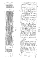
- Fig. 1 depicts a servo-tracking data storage member, or media 10, in accordance with the invention, which in the most preferred form is a magnetic tape, in particular, relatively narrow tape of the type typically provided in cartridges or cassettes which may, for example, have a width of one-quarter inch.
- a record media may, in accordance herewith, include a large number of generally parallel recording tracks, indicated generally in Fig. 1 as horizontally extending spaces delineated by lightly drawn horizontal lines.
- such a magnetic tape media formatted according to the present invention may include forty such separate tracks as illustrated herein, although additional or fewer tracks could be advantageously implemented using the format and method of the present invention.
- the record media 10 generally includes leader-type end portions 11 and 12 which include holes 13, 13', 14, 15 and 16, or the like, which serve as markers.
- the leader-type portion 11 at the forward end of media 10 typically includes punched holes 13, 13' which serve as beginning-of-tape (BOT) indicia, and a punched hole 14 which serves as a load point (LP) marker indicating the approaching start of data fields on the recording media in the forward direction of tape travel.
- BOT beginning-of-tape
- LP load point
- the leader-type portion 12 at the rearward end of media 10 typically includes a punched hole 15 which serves as an early warning (EW) marker, indicating the approaching end of the usable recording area in the forward direction, and an end-of-tape (EOT) indicia 16 identifying the end extremity of the media.
- EW early warning
- EOT end-of-tape
- recording member 10 is formatted to have dedicated or restricted areas 17, 18 at the beginning and end of record media 10, between BOT indicia 13' and LP marker 14 and between EW marker 15 and EOT indicia 16, respectively.
- the dedicated or restricted areas 17, 18, at the beginning and end of the recording media 10, respectively, are devoted exclusively to the presence of prerecorded servo-tracking and track-identifying information, as explained further hereinafter.
- recording member 10 includes data fields 19 which may be considered to be segregated or demarked from one another by recorded servo-tracking indicia, i.e., recorded signal patterns forming relatively narrow servo zones, designated by the numeral 20, and described more fully hereinafter.
- recorded servo-tracking indicia i.e., recorded signal patterns forming relatively narrow servo zones, designated by the numeral 20, and described more fully hereinafter.
- dedicated areas 17, 18 at the beginning and end of media 10, respectively, mentioned briefly above, are illustrated in more detail in Figs. 2 and 3, respectively.
- Area 17 in Fig. 2 will be described in detail as being exemplary of both such areas except for those specific differences pointed out hereinafter.
- dedicated area 17 includes alternating repetitive patterns of servo zones 20 and track-identification regions 21.
- each of the different recording tracks are indicated by the horizontal lines, the first ten of which are designated I-X, inclusive, which are to be understood as falling along the centerline of each such track.
- Each such track is uniquely identified in the track-identification region 21 such that it may be located and followed by a transducer whose position is maintained along the track centerline by a servo system using the centering signals of the servo zones 20.
- each of the tracks I-X may be identified by track numbers which are encoded using a binary code, recorded on the tape in the regions 21.
- the binary code most preferably utilizes signals wherein a one is represented by a long signal length and a zero is represented by a short signal length in the direction of longitudinal tape transport.
- Even-numbered tracks are most preferably positioned in a forward-half 22 of the track-identification regions 21 and odd-numbered tracks are most preferably positioned in a rearward-half 23 of the track-identification regions 21, relative to the direction of travel of storage media 10, when the track identification signals are read therefrom.
- two adjacent tracks have the same code and the odd and even tracks are identified by the location of their respective track-identification signals in the track-identification region.
- dedicated area 18 is identical to dedicated area 17 except that the track-identification signals in regions 21 of dedicated area 18 are reversed from the track-identification signals in dedicated area 17. Accordingly, the track-identification signals read from dedicated area 17 in the forward direction of tape travel are the same as the track-identification signals read from the dedicated area 18 in the reverse direction of tape travel, with the most significant bit of the code read first in both directions of travel.
- Each of the servo zones 20 in dedicated areas 17, 18 includes a first magnetically recorded stripe 24 and a second such stripe 25 which together define the lateral perimeters of each such servo zone, and these zones also contain a pair of vertical columns A, B of magnetically recorded servo-tracking bursts, as generally shown.
- nineteen servo zones 20 and eighteen track-identification regions 21 are provided in each of the dedicated servo areas 17, 18, although only two servo zones 20 and one track-identifying region 21 are shown in Figs. 2 and 3 for purposes of illustration.
- Each of the track-identification regions 21 in dedicated areas 17, 18 are of generally uniform dimension.
- Each of the servo zones 20 in dedicated areas 17 is also of generally uniform dimension.
- the column A and B bursts in the servo zones within dedicated area 18 may be reversed from those in area 17 such that the order in which the A and B bursts in area 18 are read in the reverse direction of tape travel is the same as the order in which the A and B columns in dedicated area 17 are read in the forward direction of tape travel.
- recording member 10 is located between LP marker 14 and EW marker 15, and as already indicated, is formatted to have repetitive, alternating user data record fields 19 which are set apart from one another by servo zones 20 which comprise track-centering signals positioned between the elongated stripes 24, 25 which extend the entire width of the tape.
- the general format is that illustrated in Fig. 5, in which a fragmentary part of a pair of successive data record fields 19 and 19' are shown and represented to include a large number of closely-spaced signal transitions which may, for example, be on the order of approximately 95 kilobytes, typically including user data as well as formatting data, as described in greater detail hereinafter.
- the various record fields 19 are written in a run-length-limited code according to conventional read-while-write data-writing techniques.
- a read-while-write writing technique data is read from the storage media immediately after it is written on the storage media, to verify that the data was accurately recorded. Those data blocks which are not accurately recorded are again recorded in a new location. The actual amount of data stored in any particular data record field 19 will thus depend upon the number of times each data block is recorded on the media before the recorder verifies that the data block was accurately recorded.
- each servo zone 20 is disposed between a pair of the elongated stripes, or boundary signals 24, 25 which extend the entire width of the recording member 10.
- the stripes 24, 25 for all the servo zones 20 are magnetically recorded on the recording member and are generally of uniform width; however, the first servo zone 20' (Fig. 2) adjacent LP marker 14 and in board thereof, includes a stripe 24' and the last servo zone 20'' (Fig. 3) of the recording member which is adjacent EW marker 15 (Fig. 1) includes a stripe 25".
- stripes 24', 25'' are at least two times greater in width than any of the other elongated stripes 24, 25 associated with other servo zones, and in the most preferred embodiment, stripes 24', 25'' are three times wider than such other stripes. Since the wider stripes 24', 25'' will result in a different (longer) signal upon being read, the microprocessor (not shown) of the data recorder (not shown) can readily detect the resulting signal to identify the first and last servo zones in the record field area, which are adjacent markers 14 and 15. Of course, these terminal servo zones 20' and 20'' are separated from the dedicated servo area 17, by fields 42, 43, respectively, of blank (unrecorded) tape extending therebetween.
- These fields of blank tape most preferably include the EW and LP holes 14, 15 at respective ends of the recording media 10.
- the dimension of these blank fields is preset to insure that the first servo zone 20' and the last servo zone 20'' are recorded on storage media 10 between the LP marker 14 and the EW marker 15.
- the servo zones 20 each include a pair of the two elongated stripes 24, 25, extending the entire width of the tape and defining the longitudinal regions of the servo zones. These servo stripes are preferably recorded with a flux density which is distinct from any other signal recorded on storage media 10 and a transducer reading signals on the recording media is responsive to the distinct flux density to generate an output signal having a distinctive frequency.
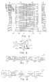
- servo zone track-centering signals 32 include an A column and a B column of tracking bursts. These tracking bursts are recorded with a flux density equal to that of the track-identification signals in region 21.
- column A includes twenty such bursts, designated by the even numerals 44-82 inclusive.
- Column B includes twenty-one such bursts designated, by the odd numerals 45-85 inclusive.
- These different odd and even-numbered bursts are preferably uniformly spaced across the width of recording member 10, with the first such bursts 45 and the last bursts 85 abutting the edges of the recording member.
- Each pair of the odd and even-numbered bursts are both vertically and horizontally contiguous such that little or no narrow vertical spacing exists between consecutive odd and even-number bursts, and their adjacent side edges define track centerlines (see I-X in Figs. 4 and 5). While the A and B columns of servo-tracking indicia are most preferably directly adjacent one another, they do not overlap at any point.
- a data frame may include thirty-two data blocks.
- Data frames most preferably include at least one data frame header which describes the contents of the data blocks that immediately follow the data frame header, i.e., the type of data block which follows.
- the data blocks may be of various types including user blocks having host data therein, control blocks storing control data, identifier blocks which are reserved for the first frame of track zero, filler blocks including no valid data, error correction code (ECC) blocks, and end-of-data (EOD) blocks.
- ECC error correction code
- EOD end-of-data
- the data frame header preferably includes data bytes identifying the method by which the data blocks are stored.
- a data frame may include more than one header, as each data frame header will describe consecutive data sequences of the same type which are stored in the same manner.
- the data blocks preferably include formatting information which is utilized by a microprocessor (not shown) in the data recorder (not shown) when reading and recovering data from storage media 10 as generally described hereinafter.
- the microprocessor preferably reads the control fields and data frame headers and is responsive thereto by outputting to the host device only the original data supplied from the host device.
- the control signals stored on the storage media are most preferably "transparent" to the host, in a preferred embodiment.
- each data block 99 is preferably formatted to include a Preamble 100 consisting of a pattern of alternating zeros and ones used by the drive (not shown) for timing purposes, as is well known and accordingly not described in greater detail herein.
- the Preamble 100 may be of normal or elongated length. Normal Preambles are provided in each data block, and may, for example, be thirteen to thirty bytes long. Elongated Preambles are recorded in the first data block of each track following a servo zone. Elongated Preambles may, for example, be ten to twelve hundred bytes long and are most preferably immediately followed by a normal Preamble.
- a Block Marker 101 which marks the start of a new block, or a new frame if the block is the first block in a frame, is also provided in each block.
- a Control Field 102 in each block includes control bytes 106 identifying the Block Number, or address.
- a control byte 107 is also provided in the Control Field to identify the physical Track Number in which the block is recorded.
- the track number control byte is particularly advantageous as the recorder includes a microprocessor which reads the control byte to identify the track with which the transducer is aligned as the blocks are read from the storage media.
- the Control Field 102 may also include a Use Count 110 which includes a pair of control bytes to identify the number of times the media has been rewritten from the beginning of the tape. Also, Control Field 102 may include a Format Type byte 108 whose value identifies a definition change regarding the processing of the other Control Field bytes, together with a Rewrite Count 109 that may be incremented upon block rewrite, thus presenting a now data pattern to a CRC generator (not shown). The rules regarding block rewrite are well understood and conventional.
- the CRC generator will then calculate four new CRC bytes for purposes of error detection in the Control Field and data field.
- the data blocks 99 additionally include a data field 103 (Fig. 7) which, for example, contains 1040 bytes of data.
- the data blocks may also contain CRC data 104 which, for example, consists of four bytes calculated to detect errors in the data field and the Control Field, as is well known.
- Each data block also includes a Postamble 105 which, like the Preamble, comprises an alternating pattern of ones and zeros. Postambles may also be of a normal or elongated length, and they are utilized by the drive for timing purposes when the recording member 10 is transported in the reverse direction. Elongated Postambles are recorded in the last data block before a servo zone.
- a stripe recorder (not specifically shown), which includes a wide write-core transducer 90 (Fig. 6), is initially used to record the sequential, spaced, comparatively wide stripes 24, 25 which preferably extend across the entire width of the storage media.
- the stripe recorder transducer 90 preferably uses a write-core gap 91 whose overall width is greater than that of the storage media 10.
- the stripe recorder preferably first measures the length of the particular storage media to be formatted by transporting the media in a first direction over its entire length. In the case of magnetic tape media, this initial forward pass may also serve as a tensioning run by which the tape is placed under a generally uniform tension along its entire length.
- Such a length measurement may readily be done using a tachometer coupled to the drive motor or capstan, which tape drives frequently include for various purposes, since by counting the number of rotations required to transport the entire length of the storage media in a forward pass, a measurement of length is provided.
- the drive controller may be used to compute the number of data fields 19 that will fit on that particular media, thereby also determining where the sequential servo zones will be recorded.
- the length of storage media 10 is preferably measured in each instance since commercially available storage media may have any of several nominal lengths, all of which have a certain tolerance, and this tolerance can change the number of recording regions which will fit on a particular sample of recording media.
- the recording member 10 After the length of the recording member 10 is so measured, it is driven in the opposite direction of travel in a reverse pass, and during this pass the wide, spaced stripes 24, 25 are recorded at uniform intervals for all the servo regions 20 determined for the particular recording member involved, including the dedicated regions 17, 18 at the ends thereof.
- This may readily be done by use of a transducer 90 as shown in Fig. 6, by applying an energizing signal to its write coil 92, in a known manner.
- the recording device (drive) to be used in this process will, as is typical, have a motor and drive mechanism which drives the storage media itself at different speeds throughout transport of the tape, the spacing of the servo stripes on the storage media may not be precisely uniform, although the spacing will preferably not vary significantly. All of the stripes 24, 25, etc. (including the extra-wide stripes 28 and 37) are thus recorded on the storage media as it passes the write head 90 in this reverse pass.
- the servo-tracking signals 44-83 inclusive and 85 are recorded within the zones 20.
- the recording member 10 is most preferably placed in a second recorder, or drive, which includes a different transducer (as noted below) for recording these relatively short bursts.
- a single recorder device could be used for both types of recording, preferably by including separate heads for recording the stripes 24, 25 and the servo-tracking signals 44-83 and 85, but the use of separate recorders has certain advantages and is currently preferred.
- a preferred form of tape head which can be advantageously utilized to simultaneously record all of the servo-tracking bursts 44-85 is illustrated in co-pending patent application entitled MULTI-TRACK SERVO RECORDING HEAD (Attorney Docket No. IRW01 P-334) naming inventors Gordenker et al., the disclosure of which is incorporated herein by reference.
- This transducer includes magnetic-read transducer 93 (indicated in phantom) which detects the passage of each of the stripes 24, 25 and outputs the distinctive frequency by which they are recorded.
- circuitry For detecting this unique frequency, known types of circuitry may be used, e.g., one using an appropriately tuned filter (not shown), a comparator (not shown) and a rectifier (not shown) to output logic signals indicating whether a signal having the desired frequency is input to the LC filter from read-core transducer 93.
- the recording device used for further formatting may, for example, include a microprocessor (not shown) which receives such an output logic level and in response controls the writing of the servo burst signals on the record member.
- the recording device writes the entire B column (Fig. 9A, 9B) of servo-tracking bursts, preferably using a multi-gap write-core transducer 94 (indicated in phantom), a predetermined time period after the leading stripe 24 is detected. A predetermined time thereafter, the multi-gap write-core 95 (indicated in phantom) is energized to record the column A centering signals on storage media 10.
- the spacing of cores 93, 94, 95 and stripes 24, 25 of each zone 20, may be such that the read core 93 outputs an electrical signal indicating that the lagging stripe 25 for the particular zone 20 in which track-centering signals are recorded is beneath the read-core following recording of the second column on the storage media.
- the lagging stripe 25 will thus provide an indication to the recorder controller that column B signals are positioned within a servo zone, i.e., between stripes 24, 25.
- the servo zone is most preferably dimensioned such that the read core is beyond the trailing stripe 25 such that the available recording area of media 10 is as large as possible.
- a and B bursts In actual application, it may be difficult to balance the strength of the signals from the A and B bursts because they are written by two different multi-gap write cores.
- An alternate approach to writing the servo bursts could involve using a single such core to write both the A and B bursts on two separate passes over the tape.
- the head On the first pass, the head can be positioned to align the gaps for the A column with the location of the B bursts and the A gaps could then be used to write the B bursts.
- the tape could then be rewound and the position of the head incremented to align the A column gaps with the desired location of the A bursts.
- the A bursts could then be written by the A column gaps on the second write pass over the tape. This method could guarantee the matching of the A and B bursts because they were written by the same multi-gap transducer.
- the track-identification signals of regions 21 are recorded adjacent each of the servo zones in the dedicated areas 17, 18 at the beginning and end of the recording member.
- the track-identifying indicia is most preferably recorded by using a commercial recorder head (not shown) which may in essence be of the same type used to record user data.
- the previously recorded servo-tracking signals 44-83 inclusive and 85 are preferably used to accurately align the head over each of the appropriate tracks being identified, as desired.
- track-identification signals are only recorded in the dedicated areas 17 at the beginning of recording member 10 and the dedicated area 18 at the end of the recording member 10.
- the recordable surface area of the record member between servo regions 20 other than those in the end areas 17, 18 is exclusively dedicated to user data storage, which significantly increases the data storage capacity of the recording member.
Claims (12)
- Formatiertes Servospurverfolgungs-Datenaufzeichnungsmagnetelement mit einer Speicherkapazität zum Aufzeichnen und Speichern von Daten, wobei das genannte Aufzeichnungselement eine Mehrzahl von Datenfeldern (19) auf dem Aufzeichnungselement aufweist, die die genannte Datenspeicherkapazität vorsehen, wobei die genannten Datenfelder innerhalb und entlang einer Mehrzahl allgemein paralleler Aufzeichnungsdatenspuren angeordnet sind, dadurch gekennzeichnet, daß das genannte Aufzeichnungselement ferner folgendes umfaßt:Servozonen (20) mit Spurzentrierungssignalen (A, B) zum Folgen entlang der genannten Aufzeichnungsspuren sowie mit aufgezeichneten Grenzsignalen (24, 25) angrenzend an entgegengesetzte Seiten der Spurzentrierungssignale, wobei die aufgezeichneten Grenzsignale dazu dienen, laterale Perimeter der genannten Servozonen in der Spurrichtung zu definieren, wobei ein Teil der Servozonen die genannten Datenfelder trennt; undSpuridentifizierungsbereiche (21), die nur in einem oder mehreren dedizierten Bereichen nahe den Enden des Aufzeichnungselements aufgezeichnet sind, wobei die genannten Spuridentifizierungsbereiche Signale aufweisen, die so codiert sind, daß sie jede Datenspur der Mehrzahl von Datenspuren in den Datenfeldern eindeutig identifizieren.
- Formatiertes Servospurverfolgungs-Datenaufzeichnungsmagnetelement nach Anspruch 1, wobei das genannte Aufzeichnungselement Magnetband umfaßt.
- Formatiertes Servospurverfolgungs-Datenaufzeichnungsmagnetelement nach Anspruch 1 oder 2, wobei ein Abschnitt der Servozonen und die Spuridentifizierungsbereiche wechselweise angeordnet sind.
- Formatiertes Servospurverfolgungs-Datenaufzeichnungsmagnetelement nach einem der vorstehenden Ansprüche, wobei das genannte Aufzeichnungselement an den Enden des genannten Bands Markierungen (14, 15) aufweist, und wobei bestimmte Servozonen (20', 20") angrenzend an eines der Datenfelder angeordnet sind, und wobei eine der genannten Markierungen einen breiteren der aufgezeichneten Grenzbereiche (24', 25") als die andere Servozone zur Identifizierung der Bandenden aufweist.
- Formatiertes Servospurverfolgungs-Datenaufzeichnungsmagnetelement nach einem der vorstehenden Ansprüche, wobei das Element ferner in den genannten Datenfeldern aufgezeichnete Benutzerdaten aufweist, wobei die genannten Daten Formatierungsdaten aufweisen, wobei die genannten Formatierungsdaten Signale aufweisen, welche die Spur identifizieren, in der die genannten Daten aufgezeichnet werden.
- Formatiertes Servospurverfolgungs-Datenaufzeichnungsmagnetelement nach Anspruch 2, wobei die genannten Datenfelder auf dem genannten Band zwischen einer Ladepunktmarkierung (14) und einer darauf angeordneten Frühwarnmarkierung (15) positioniert sind; und
wobei die Spuridentifizierungsbereiche (21) in der Vorwärtsbewegungsrichtung des Bands vor der genannten Ladepunktmarkierung und hinter der genannten Frühwarnmarkierung angeordnet sind. - Formatiertes Servospurverfolgungs-Datenaufzeichnungsmagnetelement nach Anspruch 6, wobei die genannten Servozonen (20) und Spuridentifizierungsbereiche (21) wechselweise am Anfang und am Ende des Bands wiederholt werden.
- Formatiertes Servospurverfolgungs-Datenaufzeichnungsmagnetelement nach Anspruch 6, wobei eine erste Servozone (20') zwischen der genannten Ladepunktmarkierung (14) und einem der genannten Datenfelder (19) aufgezeichnet wird, und wobei eine zweite Servozone (20") zwischen der genannten Frühwarnmarkierung (15) und einem der genannten Datenfelder aufgezeichnet wird, wobei jede der genannten ersten und zweiten Servozonen einen Bereich der aufgezeichneten Grenzsignale (24', 25") mit einer Breite aufweist, die größer ist als die anderen aufgezeichneten Grenzsignale, die auf dem genannten Aufzeichnungselement aufgezeichnet sind.
- Formatiertes Servospurverfolgungs-Datenaufzeichnungsmagnetelement nach Anspruch 1, wobei die genannten aufgezeichneten Grenzsignale folgendes umfassen:Datenfelder auf dem genannten Aufzeichnungselement, wobei die genannten Datenfelder eine Mehrzahl von Datenspuren aufweisen, um darin Datensignale zu speichern, wobei die in den genannten Datenfeldern gespeicherten Datensignale Formatierungsdaten aufweisen, wobei die genannten Formatierungsdaten Signale aufweisen, die die bestimmte Spur identifizieren, auf der die Datensignale aufgezeichnet sind; undServozonen, die mit einer Flußdichte aufgezeichnet werden, die sich von den anderen Signalen unterscheidet, die auf dem Speicherelement aufgezeichnet sind.
- Verfahren zur Formatierung eines Aufzeichnungsmagnetelements, so daß dieses eine Mehrzahl von Datenspeicherfeldern aufweist, die parallele Spuren aufweisen, wobei das genannte Verfahren die folgenden Schritte umfaßt:Aufzeichnen einer Mehrzahl von Streifen (24, 25) auf dem genannten Aufzeichnungselement mit einer Flußdichte, die sich von anderen später auf dem Aufzeichnungselement aufgezeichneten Signalen unterscheidet, wobei die genannten Streifen den Längsperimeter der Servozonen (20) auf dem genannten Aufzeichnungselement definieren; undAufzeichnen von Spurzentrierungssignalen (A, B) in den genannten Servozonen zwischen und angrenzend an ein Paar der genannten Streifen, wobei mindestens einer der genannten Streifen erfaßt wird, und wobei die genannten Spurzentrierungssignale im Verhältnis zu dem genannten Streifen positioniert werden sowie innerhalb der dadurch definieren Servozone, wobei die genannten Spurzentrierungssignale eine Einrichtung zur Identifizierung der Mitte mindestens einer der Datenspuren in den genannten Datenfeldern aufweisen.
- Verfahren nach Anspruch 10, wobei das Verfahren ferner den Schritt des Aufzeichnens von Spuridentifizierungsbereichen (21) auf dem genannten Aufzeichnungselement nur in einem oder mehreren dedizierten Bereichen nahe den Enden des Aufzeichnungselements umfaßt, wobei die genannten Spuridentifizierungsbereiche jede der genannten Spuren in den genannten Datenfeldern eindeutig identifizieren.
- Verfahren nach Anspruch 10 oder 11, wobei die genannten Streifen (24, 25) auf dem genannten Aufzeichnungselement unter Verwendung eines ersten Meßwandlers aufgezeichnet werden, der einen Schreibkern aufweist, der sich im wesentlichen über die gesamte Breite des Aufzeichnungselements zum Aufzeichnen der genannten Streifen erstreckt, um sich in einem einzigen Durchlauf im wesentlichen über die gesamte Breite des Aufzeichnungselements zu erstrecken.
Applications Claiming Priority (2)
| Application Number | Priority Date | Filing Date | Title |
|---|---|---|---|
| US07/855,239 US5396376A (en) | 1992-03-23 | 1992-03-23 | Multi-track embedded servo recording format and method |
| US855239 | 1992-03-23 |
Publications (3)
| Publication Number | Publication Date |
|---|---|
| EP0562563A2 EP0562563A2 (de) | 1993-09-29 |
| EP0562563A3 EP0562563A3 (en) | 1994-08-24 |
| EP0562563B1 true EP0562563B1 (de) | 1998-05-20 |
Family
ID=25320718
Family Applications (1)
| Application Number | Title | Priority Date | Filing Date |
|---|---|---|---|
| EP93104792A Expired - Lifetime EP0562563B1 (de) | 1992-03-23 | 1993-03-23 | Format zum eingebetteter Servo-Information und Verfahren Mehrspuraufzeichnen |
Country Status (5)
| Country | Link |
|---|---|
| US (1) | US5396376A (de) |
| EP (1) | EP0562563B1 (de) |
| JP (2) | JP3332966B2 (de) |
| CA (1) | CA2070969A1 (de) |
| DE (1) | DE69318610T2 (de) |
Families Citing this family (46)
| Publication number | Priority date | Publication date | Assignee | Title |
|---|---|---|---|---|
| US5521774A (en) * | 1994-03-18 | 1996-05-28 | Cartesian Data, Inc. | Memory storage module for storing and accessing |
| GB2323240B (en) * | 1994-04-12 | 1998-12-09 | Mitsubishi Electric Corp | Digital vtr |
| JP3322998B2 (ja) | 1994-04-12 | 2002-09-09 | 三菱電機株式会社 | ディジタルvtr |
| DE69421072T2 (de) * | 1994-05-23 | 2000-04-20 | St Microelectronics Srl | Vorrichtung zur Verarbeitung von Servosignalen in einer in Parallelarchitektur ausgeführten Lesevorrichtung für Festplatten |
| US5452150A (en) * | 1994-06-27 | 1995-09-19 | Minnesota Mining And Manufacturing Company | Data cartridge with magnetic tape markers |
| US5602703A (en) * | 1994-12-27 | 1997-02-11 | Seagate Technology, Inc. | Recording head for recording track-centering servo signals on a multi-track recording medium |
| US5815337A (en) * | 1995-10-24 | 1998-09-29 | Seagate Technology, Inc. | Tape drive having an arcuate scanner and a method for calibrating the arcuate scanner |
| KR19980701249A (ko) * | 1995-11-08 | 1998-05-15 | 요트. 게. 아. 롤페즈 | 수직 기록 매체, 수직 기록 매체 재생 방법, 기록 장치, 및 판독 장치 |
| US6130792A (en) * | 1995-11-13 | 2000-10-10 | Seagate Technology, Inc. | Flat servo bursts for arcuate track scanner |
| US5847892A (en) * | 1995-11-13 | 1998-12-08 | Seagate Technology, Inc. | Servoing and formatting magnetic recording tape in an arcuate scanner system |
| US5796537A (en) * | 1995-11-13 | 1998-08-18 | Seagate Technology, Inc. | Method and arrangement for servoing and formatting magnetic recording tape |
| US5920439A (en) * | 1997-02-21 | 1999-07-06 | Storage Technology Corporation | Method for determining longitudinal position on a magnetic tape having an embedded position count field |
| US5963400A (en) * | 1997-02-21 | 1999-10-05 | Storage Technology Corporation | Thin film tape head including split top pole |
| US5926339A (en) * | 1997-02-21 | 1999-07-20 | Storage Technology Corporation | Method for servo track identification |
| US6018429A (en) * | 1997-02-21 | 2000-01-25 | Storage Technology Corporation | Tape servo pattern with embedded servo track number identification |
| US6075666A (en) * | 1997-02-21 | 2000-06-13 | Storage Technology Corporation | Tape servo pattern having an embedded position count field |
| US6023385A (en) * | 1997-02-21 | 2000-02-08 | Storage Technology Corporation | Tape servo pattern with enhanced synchronization properties |
| US5898533A (en) * | 1997-02-21 | 1999-04-27 | Storage Technology Corporation | Tape servo pattern with embedded servo track number identification |
| US5973869A (en) * | 1997-02-21 | 1999-10-26 | Storage Technology Corporation | Servo frame edge detection for tape servo pattern with synchronization field |
| US5946156A (en) * | 1997-03-04 | 1999-08-31 | Imation Corp. | Tape servo system and methods, write/read heads, and servo track configurations regarding same |
| US6134070A (en) * | 1997-05-22 | 2000-10-17 | Imation Corp. | Encoded servo track configurations, servo writer and systems/method regarding same |
| EP0940812B1 (de) * | 1998-03-04 | 2006-11-15 | Hewlett-Packard Company, A Delaware Corporation | Absolute longitudinale Positionskodierung in linearen Bandsystemen |
| JP4022373B2 (ja) * | 1998-03-30 | 2007-12-19 | イメイション・コーポレイション | 長手方向位置情報が書き込まれたテープサーボパターン |
| EP1271477B1 (de) * | 1998-03-30 | 2006-03-01 | Imation Corp. | Band-Servomuster mit verbesserten Synchronisationseigenschaften |
| EP1075693A4 (de) * | 1998-03-30 | 2002-06-12 | Storage Technology Corp | Servospur-erkennungsverfahren |
| US6462898B2 (en) * | 1998-06-16 | 2002-10-08 | International Business Machines Corporation | Disk drive with information encoded in the position error signal fields |
| DE19846835A1 (de) * | 1998-10-10 | 2000-04-13 | Thomson Brandt Gmbh | Verfahren zur Spurlageregelung |
| EP1205913A4 (de) * | 1999-02-17 | 2002-08-14 | Quantum Corp | Methode zum schreiben von servosignalen auf magnetband |
| US6330123B1 (en) | 1999-05-28 | 2001-12-11 | Imation Corp. | Head assembly having a single pass servo writer |
| US6583675B2 (en) * | 2001-03-20 | 2003-06-24 | Broadcom Corporation | Apparatus and method for phase lock loop gain control using unit current sources |
| US6665137B2 (en) * | 2001-06-07 | 2003-12-16 | Quantum Corporation | Method for locating data tracks on a tape media |
| US7102839B2 (en) * | 2003-10-31 | 2006-09-05 | International Business Machines Corporation | Magnetic recording channel utilizing control fields for timing recovery, equalization, amplitude and amplitude asymmetry |
| US7142381B2 (en) * | 2003-11-10 | 2006-11-28 | Imation Corp. | Servo writing devices for creating servo patterns with inherent track ID |
| US7038871B2 (en) * | 2003-11-10 | 2006-05-02 | Imation Corp. | Multi-band servo patterns with inherent track ID |
| US7038872B2 (en) * | 2003-11-10 | 2006-05-02 | Imation Corp. | Servo patterns with inherent track ID |
| US8140744B2 (en) * | 2004-07-01 | 2012-03-20 | Seagate Technology Llc | Method and system for increasing data storage reliability and efficiency via compression |
| US7508609B2 (en) * | 2006-10-25 | 2009-03-24 | Spectra Logic Corporation | Formatted storage media providing space for encrypted text and dedicated space for clear text |
| JP4983460B2 (ja) * | 2007-07-23 | 2012-07-25 | ソニー株式会社 | データ再生装置、データ再生方法、及びデータ記録再生装置 |
| JP2009032375A (ja) * | 2007-07-30 | 2009-02-12 | Sony Corp | トラックフォーマット、記録媒体、記録装置、記録方法、再生装置、再生方法、及び記録再生装置 |
| US7724466B2 (en) * | 2008-02-25 | 2010-05-25 | International Business Machines Corporation | Method and system for servo stripe width detection and compensation |
| JP4930617B2 (ja) * | 2010-03-26 | 2012-05-16 | ソニー株式会社 | 磁気テープ装置 |
| EP2612298A4 (de) | 2010-09-03 | 2017-01-04 | Telefonaktiebolaget LM Ericsson (publ) | Co-kompression und co-dekompression von datenwerten |
| US8924611B2 (en) * | 2012-06-26 | 2014-12-30 | Intel Corporation | Providing a serial protocol for a bidirectional serial interconnect |
| US9710406B2 (en) | 2014-12-15 | 2017-07-18 | Intel Corporation | Data transmission using PCIe protocol via USB port |
| US10363111B2 (en) * | 2016-02-05 | 2019-07-30 | Johnson & Johnson Surgical Vision, Inc. | Phacoemulsification surgical multi-use pack usage tracker system |
| US11138996B1 (en) * | 2020-05-08 | 2021-10-05 | Western Digital Technologies, Inc. | Data storage device employing embedded servo sectors for magnetic tape |
Family Cites Families (16)
| Publication number | Priority date | Publication date | Assignee | Title |
|---|---|---|---|---|
| US4390917A (en) * | 1979-07-24 | 1983-06-28 | Olympus Optical Co., Ltd. | Device for detecting edge of magnetic tape for recording signals |
| JPS5779578A (en) * | 1980-11-05 | 1982-05-18 | Toshiba Corp | Retrieval device for picture information storage |
| DE3112886A1 (de) * | 1981-03-31 | 1982-10-14 | Tandberg Data A/S, Oslo | Verfahren zum erkennen einer kante eines magnetischen mediums und vorrichtung zur druchfuehrung des verfahrens |
| US4472750A (en) * | 1981-07-02 | 1984-09-18 | Irwin Magnetic Systems, Inc. | Data record with pre-recorded transducer positioning signals, and system for utilizing same |
| US4414593A (en) * | 1981-10-08 | 1983-11-08 | Archive Corporation | Streaming cartridge tape drive |
| US4492993A (en) * | 1982-12-14 | 1985-01-08 | Rosstream Research Associates, Ltd. | Magnetic recording tape and corresponding method providing indication of end-of-tape conditions |
| US4586094A (en) * | 1984-03-13 | 1986-04-29 | Irwin Magnetic Systems, Inc. | Method and apparatus for pre-recording tracking information on magnetic media |
| JP2593437B2 (ja) * | 1985-09-24 | 1997-03-26 | 株式会社東芝 | 磁気デイスクのサーボ位置決め装置 |
| US4858039A (en) * | 1988-02-04 | 1989-08-15 | Archive Corporation | Streaming tape drive with direct block addressability |
| US4979051A (en) * | 1988-03-22 | 1990-12-18 | Eggebeen James A | Bimodal multi-track magnetic head |
| US5003408A (en) * | 1988-08-04 | 1991-03-26 | Irwin Magnetic Systems, Inc. | Method and apparatus for removing data stream variations |
| US5055951A (en) * | 1989-03-10 | 1991-10-08 | Irwin Magnetic Systems, Inc. | Method and apparatus for servo-positioning movable transducer heads |
| JP2612337B2 (ja) * | 1989-03-29 | 1997-05-21 | 三菱電機株式会社 | 磁気ヘッドの位置決めのためのサーボ情報の記録・検出方法 |
| US5079654A (en) * | 1989-05-30 | 1992-01-07 | Teac Corporation | Data transducer position control system for data transfer apparatus employing dislike record media |
| US5073834A (en) * | 1990-01-17 | 1991-12-17 | International Business Machines Corporation | Disk file or tape drive with high servo sample rate embedding additional servo sectors within individual data sectors |
| JPH05182131A (ja) * | 1991-06-07 | 1993-07-23 | Minnesota Mining & Mfg Co <3M> | マルチチャンネルヘッドアセンブリと書き込み装置と磁気記録媒体 |
-
1992
- 1992-03-23 US US07/855,239 patent/US5396376A/en not_active Expired - Lifetime
- 1992-06-10 CA CA002070969A patent/CA2070969A1/en not_active Abandoned
- 1992-10-22 JP JP28467992A patent/JP3332966B2/ja not_active Expired - Fee Related
-
1993
- 1993-03-23 EP EP93104792A patent/EP0562563B1/de not_active Expired - Lifetime
- 1993-03-23 DE DE69318610T patent/DE69318610T2/de not_active Expired - Fee Related
-
2002
- 2002-06-18 JP JP2002177059A patent/JP3548562B2/ja not_active Expired - Fee Related
Also Published As
| Publication number | Publication date |
|---|---|
| EP0562563A3 (en) | 1994-08-24 |
| JP3548562B2 (ja) | 2004-07-28 |
| EP0562563A2 (de) | 1993-09-29 |
| JP2003022503A (ja) | 2003-01-24 |
| DE69318610D1 (de) | 1998-06-25 |
| CA2070969A1 (en) | 1993-09-24 |
| US5396376A (en) | 1995-03-07 |
| JPH05290518A (ja) | 1993-11-05 |
| DE69318610T2 (de) | 1998-12-03 |
| JP3332966B2 (ja) | 2002-10-07 |
Similar Documents
| Publication | Publication Date | Title |
|---|---|---|
| EP0562563B1 (de) | Format zum eingebetteter Servo-Information und Verfahren Mehrspuraufzeichnen | |
| US4422111A (en) | High capacity data cartridge system and preformatted cartridge for use therein | |
| CA1232066A (en) | Method and apparatus for pre-recording tracking information on magnetic media | |
| JP4266423B2 (ja) | 位置情報を確定する方法及び線形データ記憶テープ及びテープヘッドの位置決定方法 | |
| US4472750A (en) | Data record with pre-recorded transducer positioning signals, and system for utilizing same | |
| US6134070A (en) | Encoded servo track configurations, servo writer and systems/method regarding same | |
| US4492993A (en) | Magnetic recording tape and corresponding method providing indication of end-of-tape conditions | |
| US7495859B2 (en) | Interleaved servo pattern | |
| US6557141B1 (en) | Magnetic media certification | |
| US5287225A (en) | System for positioning a head in a transverse reference position on a multitrack digital magnetic tape | |
| US4819092A (en) | Apparatus for writing signal density information on a magnetic medium | |
| EP0940812B1 (de) | Absolute longitudinale Positionskodierung in linearen Bandsystemen | |
| US4796125A (en) | Optimizing the positioning of a pair of magnetic heads relative to spaced tracks on magnetic tape | |
| US5416642A (en) | Dust-immune method and apparatus for gain control of a read amplifier in a magnetic tape transport | |
| WO1994012975A1 (en) | Method and apparatus for tape track identification | |
| US5367414A (en) | Transducer/track alignment method for magnetic recording media | |
| EP0035539B1 (de) | Datenkassettensystem mit grosser kapazität | |
| US6665137B2 (en) | Method for locating data tracks on a tape media | |
| US6906881B2 (en) | Apparatus and method to erase a magnetic tape | |
| JPH0785436A (ja) | オートトラッキング方法 |
Legal Events
| Date | Code | Title | Description |
|---|---|---|---|
| PUAI | Public reference made under article 153(3) epc to a published international application that has entered the european phase |
Free format text: ORIGINAL CODE: 0009012 |
|
| AK | Designated contracting states |
Kind code of ref document: A2 Designated state(s): DE FR GB IT SE |
|
| PUAL | Search report despatched |
Free format text: ORIGINAL CODE: 0009013 |
|
| AK | Designated contracting states |
Kind code of ref document: A3 Designated state(s): DE FR GB IT SE |
|
| RAP1 | Party data changed (applicant data changed or rights of an application transferred) |
Owner name: CONNER PERIPHERALS, INC. |
|
| 17P | Request for examination filed |
Effective date: 19950131 |
|
| 17Q | First examination report despatched |
Effective date: 19960930 |
|
| GRAG | Despatch of communication of intention to grant |
Free format text: ORIGINAL CODE: EPIDOS AGRA |
|
| GRAG | Despatch of communication of intention to grant |
Free format text: ORIGINAL CODE: EPIDOS AGRA |
|
| GRAH | Despatch of communication of intention to grant a patent |
Free format text: ORIGINAL CODE: EPIDOS IGRA |
|
| RAP1 | Party data changed (applicant data changed or rights of an application transferred) |
Owner name: SEAGATE TECHNOLOGY, INC. |
|
| GRAH | Despatch of communication of intention to grant a patent |
Free format text: ORIGINAL CODE: EPIDOS IGRA |
|
| GRAA | (expected) grant |
Free format text: ORIGINAL CODE: 0009210 |
|
| AK | Designated contracting states |
Kind code of ref document: B1 Designated state(s): DE FR GB IT SE |
|
| PG25 | Lapsed in a contracting state [announced via postgrant information from national office to epo] |
Ref country code: IT Free format text: LAPSE BECAUSE OF FAILURE TO SUBMIT A TRANSLATION OF THE DESCRIPTION OR TO PAY THE FEE WITHIN THE PRE;WARNING: LAPSES OF ITALIAN PATENTS WITH EFFECTIVE DATE BEFORE 2007 MAY HAVE OCCURRED AT ANY TIME BEFORE 2007. THE CORRECT EFFECTIVE DATE MAY BE DIFFERENT FROM THE ONE RECORDED.SCRIBED TIME-LIMIT Effective date: 19980520 Ref country code: FR Free format text: LAPSE BECAUSE OF FAILURE TO SUBMIT A TRANSLATION OF THE DESCRIPTION OR TO PAY THE FEE WITHIN THE PRESCRIBED TIME-LIMIT Effective date: 19980520 |
|
| REF | Corresponds to: |
Ref document number: 69318610 Country of ref document: DE Date of ref document: 19980625 |
|
| PG25 | Lapsed in a contracting state [announced via postgrant information from national office to epo] |
Ref country code: SE Free format text: LAPSE BECAUSE OF FAILURE TO SUBMIT A TRANSLATION OF THE DESCRIPTION OR TO PAY THE FEE WITHIN THE PRESCRIBED TIME-LIMIT Effective date: 19980820 |
|
| EN | Fr: translation not filed | ||
| PLBE | No opposition filed within time limit |
Free format text: ORIGINAL CODE: 0009261 |
|
| STAA | Information on the status of an ep patent application or granted ep patent |
Free format text: STATUS: NO OPPOSITION FILED WITHIN TIME LIMIT |
|
| 26N | No opposition filed | ||
| REG | Reference to a national code |
Ref country code: GB Ref legal event code: 732E |
|
| REG | Reference to a national code |
Ref country code: GB Ref legal event code: IF02 |
|
| PGFP | Annual fee paid to national office [announced via postgrant information from national office to epo] |
Ref country code: GB Payment date: 20040301 Year of fee payment: 12 |
|
| PGFP | Annual fee paid to national office [announced via postgrant information from national office to epo] |
Ref country code: DE Payment date: 20040330 Year of fee payment: 12 |
|
| PG25 | Lapsed in a contracting state [announced via postgrant information from national office to epo] |
Ref country code: GB Free format text: LAPSE BECAUSE OF NON-PAYMENT OF DUE FEES Effective date: 20050323 |
|
| PG25 | Lapsed in a contracting state [announced via postgrant information from national office to epo] |
Ref country code: DE Free format text: LAPSE BECAUSE OF NON-PAYMENT OF DUE FEES Effective date: 20051001 |
|
| GBPC | Gb: european patent ceased through non-payment of renewal fee |
Effective date: 20050323 |