EP0662655A2 - Method and system for customizing a data processing system graphical user interface - Google Patents
Method and system for customizing a data processing system graphical user interface Download PDFInfo
- Publication number
- EP0662655A2 EP0662655A2 EP94480165A EP94480165A EP0662655A2 EP 0662655 A2 EP0662655 A2 EP 0662655A2 EP 94480165 A EP94480165 A EP 94480165A EP 94480165 A EP94480165 A EP 94480165A EP 0662655 A2 EP0662655 A2 EP 0662655A2
- Authority
- EP
- European Patent Office
- Prior art keywords
- user interface
- graphical user
- region
- data processing
- processing system
- Prior art date
- Legal status (The legal status is an assumption and is not a legal conclusion. Google has not performed a legal analysis and makes no representation as to the accuracy of the status listed.)
- Withdrawn
Links
Images


Classifications
-
- G—PHYSICS
- G06—COMPUTING; CALCULATING OR COUNTING
- G06F—ELECTRIC DIGITAL DATA PROCESSING
- G06F3/00—Input arrangements for transferring data to be processed into a form capable of being handled by the computer; Output arrangements for transferring data from processing unit to output unit, e.g. interface arrangements
- G06F3/01—Input arrangements or combined input and output arrangements for interaction between user and computer
- G06F3/048—Interaction techniques based on graphical user interfaces [GUI]
- G06F3/0481—Interaction techniques based on graphical user interfaces [GUI] based on specific properties of the displayed interaction object or a metaphor-based environment, e.g. interaction with desktop elements like windows or icons, or assisted by a cursor's changing behaviour or appearance
Definitions
- the present invention relates in general to a method and system for modifying functions and/or features of graphic user interface elements within a data processing system and in particular to a method and system for the installation of optional functions and/or features in system-wide and application specific graphic user interface environments. Still more particularly, the present invention relates to a method and system for modifying functions and/or features of graphic user interface environments utilizing graphic manipulation of selected graphic user interface elements to initiate the installation of optional functions and/or features.
- GUIs graphical user interfaces
- GUIs While such GUIs have shortened the time required for inexperienced users to learn to operate a data processing system, and increased the efficiency of experienced data processing system users, many data processing system users desire the capability to add additional functions and/or features to such GUI environments. Such additional functions and/or features may enhance the operation of, or add new features to, a system-wide GUI environment, or a GUI environment created by a selected application program.
- Norton Desktop 2.0 by Symantec Corp., of Cupertino, California, is an example of a software package that enhances the operation of Windows, a system-wide GUI, provided by Microsoft Corp., of Redmond, Washington.
- Norton Desktop enhances the display of system-generated directory windows by adding a user-definable button bar, from which a user may view, edit, and otherwise manipulate selected files directly. Such a button bar is usually displayed along the bottom edge of an open directory window.
- Today, system-wide customization (i.e., modification of functions and/or features) of a GUI environment in a known system may be accomplished by placing optional functions and/or features into designated directories or folders within the data processing system start-up disk. Examples of functions or features which may be added to a window in this manner include a display of a clock or timing device, or a display of the current vertical and horizontal position of a cursor. Thereafter, as the data processing system boots at start-up, these optional functions and/or features are loaded and incorporated into the system software, and thereafter modify the system software, to provide an optional function and/or feature.
- a user may be required to utilize dialog boxes and/or control panels provided by the manufacturer of the application software.
- Figure 1 illustrates one example of a known control panel 2 which may be utilized to customize an application-generated GUI.
- Control panel 2 utilizes two list boxes: list box 4 and list box 6.
- List box 4 indicates the optional functions and/or features which are available for customizing the GUI
- list box 6 indicates the optional functions and/or features already installed in the application-generated GUI.
- a group of pushbuttons 8 are utilized to load (i.e., install) or move (i.e., remove) optional functions and/or features.
- Such installation control panels may be more suited for the installation of fonts and small utility programs called desk accessories, rather than for the installation of optional functions, which may require a user to select a location for a display associated with that particular optional function and/or feature.
- GUI environment customization may vary from one application to another, users who have mastered the customization techniques of one application may be required to learn new techniques for customizing another application. That is, there may be little or no transfer of learning from the customization process of one application to another. Furthermore, techniques for customizing different GUI elements within the same application may also vary. Therefore, a user may be required to learn three or more different techniques for varying GUI environments; one to customize the system-wide GUI, a second to customize a first characteristic of an application-generated GUI environment, and yet a third to customize other characteristics of the same application-generated GUI environment.
- a method and system are disclosed in a data processing system for customizing a graphic user interface environment by utilizing graphic manipulation of selected graphic user interface elements in order to initiate the installation of optional functions and/or features.
- a graphical user interface element within a graphic user interface is displayed within a first region of a display screen.
- a data processing system user is then permitted to temporarily remove the graphical user interface element from that first region of the display screen by temporarily rendering that graphic user interface element transparent or by temporarily displaying that graphic user interface element within an alternate region within the display screen.
- a selected area is designated within the first region, and a user-selectable object which is representative of an optional function and/or feature is displayed at the selected area within the first region, in response to that designation.
- the graphical user interface element is then restored to the first region, and the user-selectable object is thereafter displayed at the selected area within the graphical user interface element, thereby enabling a user to customize the graphical user interface element by adding an object within an existing element of a graphic user interface which represents an optional function and/or feature within the graphic user interface element.
- data processing system 10 preferably includes a processor 12 which is coupled to a keyboard 14 and a display device 16 in a manner well known in the art.
- Display device 16 preferably includes a display screen 18.
- data processing system 10 may be implemented by utilizing any suitable computer including main frame computers, mini computers, so-called personal computers, or workstations, which may be coupled to a main frame host computer.
- One example of a data processing system which may be utilized to implement the method and system of the present invention is the International Business Machines Corporation PS/2 or RS/6000.
- PS/2 and RS/6000 are registered trademarks of International Business Machines Corporation, located in Armonk, New York.
- Data processing system 10 may also include a pointing device, such as mouse 20.
- pointing device such as mouse 20.
- FIG. 3 depicts a more detailed high level block diagram which further illustrates the preferred data processing system 10 of Figure 2.
- data processing system 10 is controlled primarily by software executed within central processing unit (CPU) 30.
- CPU 30 is coupled to display 32, and receives user input from user input device 34.
- CPU 30 is also coupled to memory 36 and one or more direct access storage devices (DASDs) depicted at block 38.
- Memory 36 and DASD 38 may be utilized for storing data sets and application programs.
- User input device 34 may be implemented utilizing one or more of the following: a keyboard, a mouse, a touch sensitive tablet or screen, a joystick, a track ball, or a screen activated light pen.
- CPU 30 may also be coupled to audio output device 40 and peripheral controller 42.
- Audio output device 40 may include an amplifier and speaker system.
- Peripheral controller 42 may be utilized to control peripheral devices, such as a logic analyzer (not shown) or other electronic equipment.
- CPU 30 is preferably suitably programmed to implement the process depicted in the flowcharts of Figures 5a-5c.
- a window 50 is provided having a display area 52, which may be utilized to display application or system related text, graphics, icons, image data, or the like.
- Title bar 54 is displayed along the top of window 50, and provides a region for the display of window title 56, faceplate control icon 58, and window controls 60.
- Window title 56 may be utilized to designate an application name and/or an object name.
- An object is an item that can be manipulated as a unit and that a user may work with to perform a task.
- An object may be represented as text, image, graphic, video, or audio.
- a text file which may comprise a document created by a word processing application, may be considered an object.
- Window controls 60 may be utilized to control the display of window 50.
- a maximize button may be utilized to enlarge a window to the largest size possible for a particular view or to enlarge the size of the window to substantially fill the work place area of display screen 18.
- a minimize button may be utilized to remove window 50 from the work place, and add a minimized-window visual, such as an application-defined icon, within the work place which represents the minimized window.
- Faceplate control button 58 is provided and utilized during the GUI environment customization process in accordance with the method and system of the present invention as will be discussed below in greater detail.
- a menu bar 62 is provided. Those familiar with GUIs will appreciate that a command within menu bar 62 may be selected graphically, utilizing a pointing device, such as a mouse 20, or by the selection of a particular keyboard key associated with a selected command. Typically, upon user selection of a particular command within menu bar 62, a so-called drop down command list is provided and utilized to display individual commands which are categorized under the particular general command selected by the user from menu bar 62.
- Pointer 64 is displayed on display screen 18 and is generally moved utilizing a pointing device, such as mouse 20. Pointer 64 is utilized to designate choices and objects that a user may wish to select or otherwise interact with. As depicted in Figure 4a, pointer 64 is located overlapping faceplate control button 58. The action lines depicted above the index finger of pointer 64 indicate that a user has depressed (i.e., clicked) a button on mouse 20.
- window 50 is depicted along with window 70, which contains optional function and/or feature icons 72 and 74.
- Optional function and/or feature icon 72 is associated with an optional function and/or feature, which, when installed in a GUI element, displays a clock function.
- Optional function and/or feature icon 74 is associated with an optional function and/or feature, which, when installed in a GUI element, displays a date function.
- window 50 is depicted with a portion of title bar 54 referred to as faceplate 76 illustrated in an open position.
- faceplate 76 is a graphical user interface element, which, in normal operation, occupies a region of display screen 18 that coincides with title bar 54.
- faceplate 76 has been removed or opened in response to a user selecting faceplate control button 58, as depicted previously in Figure 4a.
- faceplate 76 When faceplate 76 is open, it appears to have pivoted along the bottom edge of title bar 54 and come to rest below title bar 54, where it partially obscures menu bar 62. By opening faceplate 76, a user may thereafter place title bar 54, in a customization mode.
- GUI user interface elements such as, for example, menu bar 62, other icons, or other graphic elements which comprise the GUI environment, may be susceptible to being placed in such a customization mode in accordance with the method and system of the present invention.
- the process of customizing a GUI environment may comprise altering the appearance or the functionality of a particular element within a GUI environment.
- an optional function and/or feature which may be associated with a GUI element, which does not modify the appearance of the GUI element immediately upon installation, but rather, may alter the functionality of such GUI element during a subsequent user interaction.
- an optional function and/or feature may be associated with window title 56 which, in response to a user selection, displays a logical location within a storage disk of the object contained in the window.
- GUI element may be selectively modified by associating an optional function and/or feature with a selected GUI element by any one of several programming techniques known in the art, such as, for example, a software patch.
- title bar 54 may be customized to display the current time and date, for example.
- a user first selects an optional function and/or feature icon, such as either optional function and/or feature icon 72 or 74, which are each associated with an optional function and/or feature that will perform a desired modification on a designated GUI element.
- an optional function and/or feature icon such as either optional function and/or feature icon 72 or 74, which are each associated with an optional function and/or feature that will perform a desired modification on a designated GUI element.
- a user may then drag the optional function and/or feature icon to a selected point within title bar 54, as illustrated by the bold arrows in Figure 4b.
- the user may drop the optional function and/or feature icon, thus locating a display associated with the optional function and/or feature and associating the optional function and/or feature with the selected GUI element.
- clock display 80 and date display 82 are depicted after being located within title bar 54. As illustrated, the user has positioned pointer 64 over faceplate control button 58, and has depressed or clicked a button on mouse 20, closing faceplate 76.
- pointer 64 over faceplate control button 58
- button on mouse 20 closing faceplate 76.
- FIG. 4d a pictorial representation is illustrated which depicts window 50 having a customized title bar 54.
- Clock display 80 and date display 82 each represents an optional function and/or feature which has been installed in title bar 54.
- Block 102 illustrates the display, within display screen 18, of a graphic user interface environment with selectably removable elements.
- selectably removable element is faceplate 76, as illustrated in Figures 4b and 4c.
- selectably removable elements may be associated with any graphically distinguishable region of a GUI environment, such as for example, a title bar, a menu bar, an icon, or any other such graphic element which comprises the GUI environment.
- the process next determines whether or not a user desires to modify the functions and/or features of a GUI environment, as depicted at decision block 104. If a user does not desire to modify functions and/or features, the process iterates until such time as a user desires to modify functions and/or features. Alternatively, if a user desires to modify functions and/or features of the GUI environment, a user may then select a graphic user interface environment for modification, as illustrated at block 106. Such a selection may be accomplished by graphically positioning a pointer, within a display screen, through the manipulation of a pointing device.
- a selectably removable element such as a faceplate
- a GUI environment may be temporarily rendered the element transparent or by depicting such a faceplate in an open position, in much the same way as a hinged access panel would appear after being opened, and as illustrated in Figures 4b and 4c.
- the process determines whether or not a user desires to add a function and/or feature to the selected GUI environment. If a user desires to add functions and/or features, the process passes to block 114 of Figure 5b, via off-page connector A, as depicted at reference numeral 112.
- FIG. 5b a process is illustrated for adding an optional function and/or feature to a GUI environment.
- the user selects an icon associated with an optional function and/or feature to be added, as illustrated at block 114.
- a user drags an icon associated with the optional function and/or feature to the display region previously occupied by the selectably removable element, as depicted at block 116.
- the user drops the icon associated with the optional function and/or feature at a selected location within the region previously occupied by the selectably removable element, as illustrated at block 118.
- the process displays the icon, or the display associated with the optional function and/or feature at the selected location, as depicted at block 120.
- the process passes to block 122 of Figure 5a, via off-page connector B, as illustrated at reference numeral 122.
- Such a process of dragging and dropping an icon associated with an optional function and/or feature is illustrated in Figure 4b.
- the user drops the icon associated with the optional function and/or feature at a selected location that is unrelated to the region previously occupied by the selectably removable element, as illustrated at block 132.
- the process then removes the icon, or display associated with the optional function and/or feature, from the region previously occupied by the selectably removable element, as depicted at block 134.
- the process passes, via off-page connector D, as depicted at reference numeral 136, to block 138 of Figure 5a.
- a user may select and place a GUI element in a customization mode by opening a faceplate, and thereafter select, drag, and drop an icon associated with an optional function and/or feature into an area within the region occupied by the selected GUI element in order to add optional functions and/or features to the GUI environment.
- One example of adding such an optional function and/or feature is the installation of a clock or calendar display within unused areas of a window title bar.
- such installation of optional functions and/or features may alter the functionality of any graphically distinguishable region of a GUI environment.
- a preferred embodiment of the present invention provides an improved method and system for modifying functions and/or features of a graphic user interface environment utilizing graphic manipulation of selected graphic user interface elements to initiate the installation of optional functions and/or features.
Abstract
A method and system in a data processing system for customizing a graphic user interface environment by utilizing graphic manipulation of selected graphic user interface elements in order to initiate the installation of optional functions and/or features. A graphical user interface element within a graphic user interface is displayed within a first region of a display screen. A data processing system user is then permitted to temporarily remove the graphical user interface element from that first region of the display screen by temporarily rendering that graphic user interface element transparent or by temporarily displaying that graphic user interface element within an alternate region within the display screen. Thereafter, a selected area is designated within the first region, and a user-selectable object which is representative of an optional function and/or feature is displayed at the selected area within the first region, in response to that designation. The graphical user interface element is then restored to the first region, and the user-selectable object is thereafter displayed at the selected area within the graphical user interface element, thereby enabling a user to customize the graphical user interface element by adding an object within an existing element of a graphic user interface which represents an optional function and/or feature within the graphic user interface element.
Description
- The present invention relates in general to a method and system for modifying functions and/or features of graphic user interface elements within a data processing system and in particular to a method and system for the installation of optional functions and/or features in system-wide and application specific graphic user interface environments. Still more particularly, the present invention relates to a method and system for modifying functions and/or features of graphic user interface environments utilizing graphic manipulation of selected graphic user interface elements to initiate the installation of optional functions and/or features.
- As data processing system computer software and hardware become increasingly complex, the interface between the data processing system and a user becomes more important. Users who have difficulty remembering, understanding, and properly entering complicated computer instructions to operate relatively simple data processing system software and hardware will surely have difficulty interfacing with such data processing systems as their capabilities, and hence their complexity, increase. If the interface between a user and a data processing system is not constantly reevaluated and improved, the rate at which data processing system manufacturers produce systems with features that require a user to enter commands which are often cryptic and complex may outpace a user's ability to learn, understand, and utilize such commands.
- In order to increase a data processing system user's efficiency, data processing system hardware and software manufacturers have recently provided so-called graphical user interfaces (GUIs). Presently, many GUIs are known to those persons skilled in the art, and each such interface provides data processing system users a more visual and intuitive means for entering data, entering commands, and viewing computational results.
- While such GUIs have shortened the time required for inexperienced users to learn to operate a data processing system, and increased the efficiency of experienced data processing system users, many data processing system users desire the capability to add additional functions and/or features to such GUI environments. Such additional functions and/or features may enhance the operation of, or add new features to, a system-wide GUI environment, or a GUI environment created by a selected application program.
- Norton Desktop 2.0, by Symantec Corp., of Cupertino, California, is an example of a software package that enhances the operation of Windows, a system-wide GUI, provided by Microsoft Corp., of Redmond, Washington. Norton Desktop enhances the display of system-generated directory windows by adding a user-definable button bar, from which a user may view, edit, and otherwise manipulate selected files directly. Such a button bar is usually displayed along the bottom edge of an open directory window.
- Today, system-wide customization (i.e., modification of functions and/or features) of a GUI environment in a known system may be accomplished by placing optional functions and/or features into designated directories or folders within the data processing system start-up disk. Examples of functions or features which may be added to a window in this manner include a display of a clock or timing device, or a display of the current vertical and horizontal position of a cursor. Thereafter, as the data processing system boots at start-up, these optional functions and/or features are loaded and incorporated into the system software, and thereafter modify the system software, to provide an optional function and/or feature. To customize a GUI environment generated by application software, a user may be required to utilize dialog boxes and/or control panels provided by the manufacturer of the application software.
- Both of the above-described methods of modifying system GUI environments and application GUI environments have substantial drawbacks. In the example of modifying a system GUI environment, the optional functions and/or features which are installed at start up typically affect GUI elements system-wide, even though a user may wish to customize only particular GUI elements under certain predetermined conditions. Thus, a data processing system user desiring to bill clients for time devoted to writing a particular document, may find it useful to have a timer displayed within a word processing application, which represents the amount of time spent writing the document. That same user, however, may not wish to have a timer displayed in every application window throughout the system.
- As for the example of installing optional functions and/or features in order to customize a GUI generated by a particular application program, a user is often confronted with a wide variety of control panels and/or dialog boxes which must be manipulated in order to install a variety of custom GUI features. Since application software is often produced by different software manufacturers having different philosophies of how a GUI should look and feel, the process of installing various optional functions and/or features to customize different application-created GUI environments may be unnecessarily complicated. Users may also desire to have a custom feature offered by one software manufacturer installed while running an application provided by another software manufacturer.
- Figure 1 illustrates one example of a known control panel 2 which may be utilized to customize an application-generated GUI. Control panel 2 utilizes two list boxes:
list box 4 and list box 6.List box 4 indicates the optional functions and/or features which are available for customizing the GUI, and list box 6 indicates the optional functions and/or features already installed in the application-generated GUI. A group ofpushbuttons 8 are utilized to load (i.e., install) or move (i.e., remove) optional functions and/or features. Such installation control panels may be more suited for the installation of fonts and small utility programs called desk accessories, rather than for the installation of optional functions, which may require a user to select a location for a display associated with that particular optional function and/or feature. - Since GUI environment customization may vary from one application to another, users who have mastered the customization techniques of one application may be required to learn new techniques for customizing another application. That is, there may be little or no transfer of learning from the customization process of one application to another. Furthermore, techniques for customizing different GUI elements within the same application may also vary. Therefore, a user may be required to learn three or more different techniques for varying GUI environments; one to customize the system-wide GUI, a second to customize a first characteristic of an application-generated GUI environment, and yet a third to customize other characteristics of the same application-generated GUI environment.
- Therefore it should be apparent that a need exist for a method and system for the installation of optional functions and/or features for customizing system-wide and application-specific GUI environments.
- It is therefore one object of the present invention to provide an improved method and system for modifying functions and/or features of graphic user interface elements within a data processing system.
- It is another object of the present invention to provide a method and system for the installation of optional functions and/or features in system-wide and application-specific graphic user interface environments.
- It is yet another object of the present invention to provide a method and system for modifying functions and/or features of graphic user interface environments utilizing graphic manipulation of selected graphic user interface elements to initiate the installation of optional functions and/or features.
- The foregoing objects are achieved as is now described. A method and system are disclosed in a data processing system for customizing a graphic user interface environment by utilizing graphic manipulation of selected graphic user interface elements in order to initiate the installation of optional functions and/or features. A graphical user interface element within a graphic user interface is displayed within a first region of a display screen. A data processing system user is then permitted to temporarily remove the graphical user interface element from that first region of the display screen by temporarily rendering that graphic user interface element transparent or by temporarily displaying that graphic user interface element within an alternate region within the display screen. Thereafter, a selected area is designated within the first region, and a user-selectable object which is representative of an optional function and/or feature is displayed at the selected area within the first region, in response to that designation. The graphical user interface element is then restored to the first region, and the user-selectable object is thereafter displayed at the selected area within the graphical user interface element, thereby enabling a user to customize the graphical user interface element by adding an object within an existing element of a graphic user interface which represents an optional function and/or feature within the graphic user interface element.
- The above as well as additional objects, features, and advantages of the present invention will become apparent in the following detailed written description.
- The novel features believed characteristic of the invention are set forth in the appended claims. The invention itself however, as well as a preferred mode of use, further objects and advantages thereof, will best be understood by reference to the following detailed description of an illustrative embodiment when read in conjunction with the accompanying drawings, wherein:
- Figure 1 depicts a prior art control panel for customizing a graphic user interface environment;
- Figure 2 is a pictorial illustration of a data processing system which may be utilized to implement a preferred embodiment of the present invention;
- Figure 3 depicts a more detailed high level block diagram, further illustrating the preferred data processing system of Figure 2;
- Figures 4a, 4b, 4c, and 4d depict pictorial representations of the method and system for customizing a graphic user interface environment that employs graphic manipulation of selected graphic user interface elements in accordance with the method and system of the present invention; and
- Figures 5a, 5b, and 5c depict a high level logic flowchart that illustrates the process of customizing a graphic user interface environment in accordance with the method and system of the present invention.
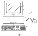
- With reference now to the figures and in particular with reference to Figure 2, there is depicted a pictorial representation of a
data processing system 10 which may be utilized to implement the method and system of the present invention. As illustrated,data processing system 10 preferably includes aprocessor 12 which is coupled to akeyboard 14 and adisplay device 16 in a manner well known in the art.Display device 16 preferably includes adisplay screen 18. Those skilled in the art will appreciate thatdata processing system 10 may be implemented by utilizing any suitable computer including main frame computers, mini computers, so-called personal computers, or workstations, which may be coupled to a main frame host computer. One example of a data processing system which may be utilized to implement the method and system of the present invention is the International Business Machines Corporation PS/2 or RS/6000. PS/2 and RS/6000 are registered trademarks of International Business Machines Corporation, located in Armonk, New York.Data processing system 10 may also include a pointing device, such asmouse 20. Those skilled in the art should also appreciate that the hardware depicted in Figure 2 may vary for specific applications. - Figure 3 depicts a more detailed high level block diagram which further illustrates the preferred
data processing system 10 of Figure 2. As illustrated,data processing system 10 is controlled primarily by software executed within central processing unit (CPU) 30.CPU 30 is coupled to display 32, and receives user input fromuser input device 34.CPU 30 is also coupled tomemory 36 and one or more direct access storage devices (DASDs) depicted atblock 38.Memory 36 andDASD 38 may be utilized for storing data sets and application programs.User input device 34 may be implemented utilizing one or more of the following: a keyboard, a mouse, a touch sensitive tablet or screen, a joystick, a track ball, or a screen activated light pen.CPU 30 may also be coupled to audio output device 40 and peripheral controller 42. Audio output device 40 may include an amplifier and speaker system. Peripheral controller 42 may be utilized to control peripheral devices, such as a logic analyzer (not shown) or other electronic equipment. In the depicted embodiment of the present invention,CPU 30 is preferably suitably programmed to implement the process depicted in the flowcharts of Figures 5a-5c. - With reference now to Figures 4a, 4b, 4c, and 4d, there are depicted pictorial representations of the customization of a graphic user interface environment which employs graphic manipulation of selected graphic user interface elements in accordance with the method and system of the present invention. As depicted, a
window 50 is provided having adisplay area 52, which may be utilized to display application or system related text, graphics, icons, image data, or the like.Title bar 54 is displayed along the top ofwindow 50, and provides a region for the display ofwindow title 56,faceplate control icon 58, and window controls 60.Window title 56 may be utilized to designate an application name and/or an object name. An object is an item that can be manipulated as a unit and that a user may work with to perform a task. An object may be represented as text, image, graphic, video, or audio. For example, a text file, which may comprise a document created by a word processing application, may be considered an object. - Window controls 60 may be utilized to control the display of
window 50. For example, a maximize button may be utilized to enlarge a window to the largest size possible for a particular view or to enlarge the size of the window to substantially fill the work place area ofdisplay screen 18. Similarly, a minimize button may be utilized to removewindow 50 from the work place, and add a minimized-window visual, such as an application-defined icon, within the work place which represents the minimized window. -
Faceplate control button 58 is provided and utilized during the GUI environment customization process in accordance with the method and system of the present invention as will be discussed below in greater detail. - Additionally, a
menu bar 62 is provided. Those familiar with GUIs will appreciate that a command withinmenu bar 62 may be selected graphically, utilizing a pointing device, such as amouse 20, or by the selection of a particular keyboard key associated with a selected command. Typically, upon user selection of a particular command withinmenu bar 62, a so-called drop down command list is provided and utilized to display individual commands which are categorized under the particular general command selected by the user frommenu bar 62. -
Pointer 64 is displayed ondisplay screen 18 and is generally moved utilizing a pointing device, such asmouse 20.Pointer 64 is utilized to designate choices and objects that a user may wish to select or otherwise interact with. As depicted in Figure 4a,pointer 64 is located overlappingfaceplate control button 58. The action lines depicted above the index finger ofpointer 64 indicate that a user has depressed (i.e., clicked) a button onmouse 20. - Referring now to Figure 4b,
window 50 is depicted along withwindow 70, which contains optional function and/or featureicons feature icon 72 is associated with an optional function and/or feature, which, when installed in a GUI element, displays a clock function. Optional function and/orfeature icon 74 is associated with an optional function and/or feature, which, when installed in a GUI element, displays a date function. - As illustrated in Figure 4b,
window 50 is depicted with a portion oftitle bar 54 referred to asfaceplate 76 illustrated in an open position. In this example,faceplate 76 is a graphical user interface element, which, in normal operation, occupies a region ofdisplay screen 18 that coincides withtitle bar 54. In Figure 4b however,faceplate 76 has been removed or opened in response to a user selectingfaceplate control button 58, as depicted previously in Figure 4a. Whenfaceplate 76 is open, it appears to have pivoted along the bottom edge oftitle bar 54 and come to rest belowtitle bar 54, where it partially obscuresmenu bar 62. By openingfaceplate 76, a user may thereafter placetitle bar 54, in a customization mode. Those persons skilled in the art should recognize that other graphic user interface elements, such as, for example,menu bar 62, other icons, or other graphic elements which comprise the GUI environment, may be susceptible to being placed in such a customization mode in accordance with the method and system of the present invention. - Those persons skilled in the art should appreciate that the process of customizing a GUI environment may comprise altering the appearance or the functionality of a particular element within a GUI environment. Alternately, it is possible to have an optional function and/or feature, which may be associated with a GUI element, which does not modify the appearance of the GUI element immediately upon installation, but rather, may alter the functionality of such GUI element during a subsequent user interaction. For example, an optional function and/or feature may be associated with
window title 56 which, in response to a user selection, displays a logical location within a storage disk of the object contained in the window. If optional functions and/or features that modify the functionality of a GUI element are associated with a GUI element, the association of such an optional function and/or feature may not be apparent by viewing the GUI element with a closed faceplate, but may only be apparent by viewing an icon associated with such an optional function and/or feature, when a faceplate associated with the GUI element is opened. - In either case, the appearance and/or functionality of a GUI element may be selectively modified by associating an optional function and/or feature with a selected GUI element by any one of several programming techniques known in the art, such as, for example, a software patch.
- Once
faceplate 76, which was located over the region occupied bytitle bar 54, has been opened,title bar 54 may be customized to display the current time and date, for example. To customizetitle bar 54, a user first selects an optional function and/or feature icon, such as either optional function and/orfeature icon title bar 54, as illustrated by the bold arrows in Figure 4b. When the optional function and/or feature icon has been dragged to a selected point within the region occupied bytitle bar 54, the user may drop the optional function and/or feature icon, thus locating a display associated with the optional function and/or feature and associating the optional function and/or feature with the selected GUI element. - Referring now to Figure 4c,
clock display 80 anddate display 82 are depicted after being located withintitle bar 54. As illustrated, the user has positionedpointer 64 overfaceplate control button 58, and has depressed or clicked a button onmouse 20, closingfaceplate 76. Those persons skilled in the art should appreciate that locating a display associated with an optional function and/or feature in a generally unused area of a GUI environment may increase a user's efficiency by providing desired information in a user-designated location, while minimizing the nonproductive use of work area within the GUI environment. - Turning now to Figure 4d, a pictorial representation is illustrated which depicts
window 50 having a customizedtitle bar 54.Clock display 80 anddate display 82, each represents an optional function and/or feature which has been installed intitle bar 54. - Finally, referring now to Figures 5a, 5b, and 5c, there are depicted high level logic flowcharts which illustrate the method and system of the present invention. As depicted, the process begins at
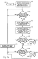
block 100 and thereafter passes to block 102.Block 102 illustrates the display, withindisplay screen 18, of a graphic user interface environment with selectably removable elements. One example of a selectably removable element isfaceplate 76, as illustrated in Figures 4b and 4c. Those persons skilled in the art should recognize that selectably removable elements may be associated with any graphically distinguishable region of a GUI environment, such as for example, a title bar, a menu bar, an icon, or any other such graphic element which comprises the GUI environment. - The process next determines whether or not a user desires to modify the functions and/or features of a GUI environment, as depicted at
decision block 104. If a user does not desire to modify functions and/or features, the process iterates until such time as a user desires to modify functions and/or features. Alternatively, if a user desires to modify functions and/or features of the GUI environment, a user may then select a graphic user interface environment for modification, as illustrated at block 106. Such a selection may be accomplished by graphically positioning a pointer, within a display screen, through the manipulation of a pointing device. - Next, as depicted at
block 108, the process temporarily removes the selectably removable element from the GUI environment selected for modification. Those persons skilled in the art should appreciate that a selectably removable element, such as a faceplate, may be temporarily removed from a GUI environment by temporarily rendering the element transparent or by depicting such a faceplate in an open position, in much the same way as a hinged access panel would appear after being opened, and as illustrated in Figures 4b and 4c. - Next, as illustrated at
block 110, the process determines whether or not a user desires to add a function and/or feature to the selected GUI environment. If a user desires to add functions and/or features, the process passes to block 114 of Figure 5b, via off-page connector A, as depicted at reference numeral 112. - Referring now to Figure 5b, a process is illustrated for adding an optional function and/or feature to a GUI environment. First, the user selects an icon associated with an optional function and/or feature to be added, as illustrated at
block 114. Thereafter, a user drags an icon associated with the optional function and/or feature to the display region previously occupied by the selectably removable element, as depicted atblock 116. Next, the user drops the icon associated with the optional function and/or feature at a selected location within the region previously occupied by the selectably removable element, as illustrated atblock 118. After the user drops such an icon, the process displays the icon, or the display associated with the optional function and/or feature at the selected location, as depicted atblock 120. Thereafter, the process passes to block 122 of Figure 5a, via off-page connector B, as illustrated atreference numeral 122. Such a process of dragging and dropping an icon associated with an optional function and/or feature is illustrated in Figure 4b. - Next, as illustrated at
block 124, a determination is illustrated as to whether or not a user desires to delete optional functions and/or features from a GUI environment. If the user desires to delete optional functions and/or features from the GUI environment, the process passes, via off-page connector C, as illustrated atreference numeral 126, to block 128 of Figure 5c. As illustrated atblock 128 in Figure 5c, the user selects an icon, within the region previously occupied by the selectably removable element, which is associated with an optional function and/or feature to be removed. Thereafter, the user drags the icon associated with the optional function and or feature from the display region previously occupied by the selectably removable element, as depicted atblock 130. Next, the user drops the icon associated with the optional function and/or feature at a selected location that is unrelated to the region previously occupied by the selectably removable element, as illustrated atblock 132. The process then removes the icon, or display associated with the optional function and/or feature, from the region previously occupied by the selectably removable element, as depicted atblock 134. Thereafter, the process passes, via off-page connector D, as depicted atreference numeral 136, to block 138 of Figure 5a. - As illustrated at
block 138 in Figure 5a, the user then replaces the selectably removable element at the position originally occupied by the selectably removable element. Thereafter, the above-described process continues in an iterative fashion. - After reading the detailed description of the preferred embodiment above, it should be apparent to those persons skilled in the applicable art that the present disclosure provides an improved method and system for graphically modifying functions and/or features in a graphical user interface environment. In a preferred embodiment, a user may select and place a GUI element in a customization mode by opening a faceplate, and thereafter select, drag, and drop an icon associated with an optional function and/or feature into an area within the region occupied by the selected GUI element in order to add optional functions and/or features to the GUI environment. One example of adding such an optional function and/or feature is the installation of a clock or calendar display within unused areas of a window title bar. Moreover, such installation of optional functions and/or features may alter the functionality of any graphically distinguishable region of a GUI environment. Thus, a preferred embodiment of the present invention provides an improved method and system for modifying functions and/or features of a graphic user interface environment utilizing graphic manipulation of selected graphic user interface elements to initiate the installation of optional functions and/or features.
Claims (8)
- A method in a data processing system having a display for graphically modifying functions and/or features of a graphical user interface having at least one graphical user interface element associated therewith, said method comprising the steps of:
displaying a graphical user interface element within a first region within said display;
temporarily removing said graphical user interface element from said first region;
designating a selected area within said first region;
displaying a user-selected representation of a desired function and/or feature within said selected area within said first region in response to said designation of said selected area;
restoring said graphical user interface element to said first region; and
thereafter displaying said user-selected representation within said selected are a within said graphical user interface element, wherein a user may graphically modify functions and/or features associated with said graphical user interface. - The method in a data processing system for graphically modifying functions and/or features of a graphical user interface according to claim 1, wherein the step of temporarily removing said graphical user interface element from said first region further comprises the step of temporarily displaying said graphical user interface element in a second region within said display.
- The method in a data processing system for graphically modifying functions and/or features of a graphical user interface according to claim 2, wherein the step of temporarily displaying said graphical user interface element in a second region within said display further comprises the step of temporarily displaying said graphical user interface element in a second region having a common boundary with said first region.
- The method in a data processing system for graphically modifying functions and/or features of a graphical user interface according to claim 1, 2 or 3, wherein said data processing system includes a pointing device and wherein said step of designating a selected area within said first region further comprises the step of designating said selected area utilizing said pointing device.
- The method in a data processing system for graphically modifying functions and/or features of a graphical user interface according to anyone of claims 1 to 4, wherein said first region includes a plurality of selected areas, and wherein said step of displaying a user-selected representation of a desired function and/or feature within said selected area within said first region in response to said designating of said selected area further comprises the step of displaying a plurality of user-selected representations of a plurality of desired functions and/or features within said plurality of selected areas.
- The method in a data processing system for graphically modifying functions and/or features of a graphical user interface according to anyone of claims 1 to 5, wherein said step of displaying said user-selected representation within said selected area within said graphical user interface element further comprises the step of displaying a time display.
- The method in a data processing system for graphically modifying functions and/or features of a graphical user interface according to anyone of claims 1 to 6, wherein said step of displaying said user-selected representation within said selected area within said graphical user interface element further comprises the step of displaying a date display.
- A data processing system implementing the methods according to anyone of claims 1 to 7.
Applications Claiming Priority (2)
| Application Number | Priority Date | Filing Date | Title |
|---|---|---|---|
| US08/177,296 US6201539B1 (en) | 1994-01-04 | 1994-01-04 | Method and system for customizing a data processing system graphical user interface |
| US177296 | 1994-01-04 |
Publications (1)
| Publication Number | Publication Date |
|---|---|
| EP0662655A2 true EP0662655A2 (en) | 1995-07-12 |
Family
ID=22648049
Family Applications (1)
| Application Number | Title | Priority Date | Filing Date |
|---|---|---|---|
| EP94480165A Withdrawn EP0662655A2 (en) | 1994-01-04 | 1994-12-06 | Method and system for customizing a data processing system graphical user interface |
Country Status (3)
| Country | Link |
|---|---|
| US (1) | US6201539B1 (en) |
| EP (1) | EP0662655A2 (en) |
| JP (1) | JP2732557B2 (en) |
Cited By (3)
| Publication number | Priority date | Publication date | Assignee | Title |
|---|---|---|---|---|
| WO2002039245A2 (en) * | 2000-11-09 | 2002-05-16 | Change Tools, Inc. | A user definable interface system, method and computer program product |
| GB2380577A (en) * | 1997-09-21 | 2003-04-09 | Microsoft Corp | Custom control for a standard user interface control specified by the data provider |
| US7810038B2 (en) | 2002-05-03 | 2010-10-05 | International Business Machines Corporation | Method for modifying a GUI for an application |
Families Citing this family (57)
| Publication number | Priority date | Publication date | Assignee | Title |
|---|---|---|---|---|
| JP2001069580A (en) * | 1999-08-31 | 2001-03-16 | Matsushita Electric Ind Co Ltd | Av unit controlling device |
| JP3773716B2 (en) | 1999-09-13 | 2006-05-10 | 富士通株式会社 | Graphical user interface display device and recording medium storing program for causing computer to execute processing in the device |
| US7895530B2 (en) * | 2000-11-09 | 2011-02-22 | Change Tools, Inc. | User definable interface system, method, support tools, and computer program product |
| US20030028619A1 (en) * | 2001-07-31 | 2003-02-06 | International Business Machines Corporation | Linking user-defined panels to existing product panels |
| US20040122915A1 (en) * | 2001-11-28 | 2004-06-24 | John Saare | Method and system for an extensible client specific calendar application in a portal server |
| US20030142143A1 (en) * | 2002-01-28 | 2003-07-31 | International Business Machines Corporation | Varying heights of application images to convey application status |
| US6954905B2 (en) * | 2002-01-28 | 2005-10-11 | International Business Machines Corporation | Displaying transparency characteristic aids |
| US7146573B2 (en) * | 2002-01-28 | 2006-12-05 | International Business Machines Corporation | Automatic window representation adjustment |
| US20030142141A1 (en) * | 2002-01-28 | 2003-07-31 | International Business Machines Corporation | Displaying specified resource usage |
| US20030142133A1 (en) * | 2002-01-28 | 2003-07-31 | International Business Machines Corporation | Adjusting transparency of windows to reflect recent use |
| US20030142137A1 (en) * | 2002-01-28 | 2003-07-31 | International Business Machines Corporation | Selectively adjusting the order of windows in response to a scroll wheel rotation |
| US20030142149A1 (en) * | 2002-01-28 | 2003-07-31 | International Business Machines Corporation | Specifying audio output according to window graphical characteristics |
| US20030142140A1 (en) * | 2002-01-28 | 2003-07-31 | International Business Machines Corporation | Adjusting the tint of a translucent window to convey status |
| US7130400B2 (en) * | 2002-04-27 | 2006-10-31 | Bellsouth Intellectual Property Corporation | Graphical animation and sound for Internet Call-Waiting messages |
| US7005846B2 (en) * | 2002-07-17 | 2006-02-28 | Agilent Technologies, Inc. | System and method for application control in measurement devices |
| US7243124B1 (en) | 2002-09-06 | 2007-07-10 | Oracle International Corporation | Architecture for general purpose near real-time business intelligence system with client devices and methods therefor |
| US7272660B1 (en) | 2002-09-06 | 2007-09-18 | Oracle International Corporation | Architecture for general purpose near real-time business intelligence system and methods therefor |
| US7912899B2 (en) * | 2002-09-06 | 2011-03-22 | Oracle International Corporation | Method for selectively sending a notification to an instant messaging device |
| US7899879B2 (en) * | 2002-09-06 | 2011-03-01 | Oracle International Corporation | Method and apparatus for a report cache in a near real-time business intelligence system |
| US7412481B2 (en) | 2002-09-16 | 2008-08-12 | Oracle International Corporation | Method and apparatus for distributed rule evaluation in a near real-time business intelligence system |
| US8165993B2 (en) * | 2002-09-06 | 2012-04-24 | Oracle International Corporation | Business intelligence system with interface that provides for immediate user action |
| US7945846B2 (en) | 2002-09-06 | 2011-05-17 | Oracle International Corporation | Application-specific personalization for data display |
| US7941542B2 (en) * | 2002-09-06 | 2011-05-10 | Oracle International Corporation | Methods and apparatus for maintaining application execution over an intermittent network connection |
| US7454423B2 (en) | 2002-09-06 | 2008-11-18 | Oracle International Corporation | Enterprise link for a software database |
| US8255454B2 (en) * | 2002-09-06 | 2012-08-28 | Oracle International Corporation | Method and apparatus for a multiplexed active data window in a near real-time business intelligence system |
| US7426059B2 (en) | 2002-09-16 | 2008-09-16 | Oracle International Corporation | Data presentation methods and apparatus to facilitate printing and reviewing |
| US7668917B2 (en) * | 2002-09-16 | 2010-02-23 | Oracle International Corporation | Method and apparatus for ensuring accountability in the examination of a set of data elements by a user |
| US7401158B2 (en) * | 2002-09-16 | 2008-07-15 | Oracle International Corporation | Apparatus and method for instant messaging collaboration |
| US20040113941A1 (en) * | 2002-12-12 | 2004-06-17 | Xerox Corporation | User interface customization |
| US7904823B2 (en) * | 2003-03-17 | 2011-03-08 | Oracle International Corporation | Transparent windows methods and apparatus therefor |
| US7184801B2 (en) * | 2003-05-12 | 2007-02-27 | Good Technology, Inc. | Mobile application builder |
| US7113964B1 (en) | 2003-06-05 | 2006-09-26 | Iteration Software, Inc. | Method and apparatus for archiving data in a relational database system |
| US7199802B2 (en) * | 2003-10-24 | 2007-04-03 | Microsoft Corporation | Multiple-mode window presentation system and process |
| US20050198610A1 (en) * | 2004-03-03 | 2005-09-08 | Ulf Fildebrandt | Providing and using design time support |
| US8181119B1 (en) * | 2004-06-02 | 2012-05-15 | Apple Inc. | User interface with inline customization |
| US7490295B2 (en) * | 2004-06-25 | 2009-02-10 | Apple Inc. | Layer for accessing user interface elements |
| US20060109242A1 (en) * | 2004-11-19 | 2006-05-25 | Simpkins Daniel S | User interface for impaired users |
| US20060123345A1 (en) * | 2004-12-06 | 2006-06-08 | International Business Machines Corporation | Platform-independent markup language-based gui format |
| AU2004325958A1 (en) * | 2004-12-21 | 2006-06-29 | Dart Chart Systems Llc | Multicultural and multimedia data collection and documentation computer system, apparatus and method |
| US8117093B2 (en) * | 2006-05-15 | 2012-02-14 | Accenture Global Services Limited | Systems, applications and products in data processing for expedite orders |
| US20070265874A1 (en) * | 2006-05-15 | 2007-11-15 | Accenture Global Services Gmbh | Systems, applications and products in data processing for partner determination |
| US8041613B2 (en) * | 2006-05-15 | 2011-10-18 | Accenture Global Services Limited | Systems, applications and products in data processing for cross dock |
| US20070276685A1 (en) * | 2006-05-15 | 2007-11-29 | Accenture Global Services Gmbh | Systems, applications and products in data processing for end customer |
| US20070276683A1 (en) * | 2006-05-15 | 2007-11-29 | Accenture Global Services Gmbh | Systems, applications and products in data processing for inter-company pricing |
| US20080082610A1 (en) * | 2006-09-29 | 2008-04-03 | Breise Devin W | Method and apparatus for providing collaborative user interface feedback |
| TW200830166A (en) * | 2007-01-15 | 2008-07-16 | Asustek Comp Inc | Method and computer system capable of presenting program graphics interface on title bar of window |
| US9791994B2 (en) | 2007-06-08 | 2017-10-17 | Apple Inc. | User interface for application interface manipulation |
| US8751920B2 (en) * | 2007-10-30 | 2014-06-10 | Perot Systems Corporation | System and method for image processing with assignment of medical codes |
| US20100333017A1 (en) * | 2007-11-27 | 2010-12-30 | David J. Ortiz | Computer graphic user interface and display system |
| US9349109B2 (en) | 2008-02-29 | 2016-05-24 | Adobe Systems Incorporated | Media generation and management |
| US8789205B2 (en) * | 2010-04-21 | 2014-07-22 | Microsoft Corporation | Role-based graphical user interfaces |
| US9202433B2 (en) | 2012-03-06 | 2015-12-01 | Apple Inc. | Multi operation slider |
| US9041727B2 (en) | 2012-03-06 | 2015-05-26 | Apple Inc. | User interface tools for selectively applying effects to image |
| US20130239063A1 (en) | 2012-03-06 | 2013-09-12 | Apple Inc. | Selection of multiple images |
| US9131192B2 (en) | 2012-03-06 | 2015-09-08 | Apple Inc. | Unified slider control for modifying multiple image properties |
| US10282055B2 (en) | 2012-03-06 | 2019-05-07 | Apple Inc. | Ordered processing of edits for a media editing application |
| US10572274B2 (en) * | 2017-09-22 | 2020-02-25 | Microsoft Technology Licensing, Llc | Cross platform custom functions |
Family Cites Families (15)
| Publication number | Priority date | Publication date | Assignee | Title |
|---|---|---|---|---|
| US4692858A (en) | 1984-02-02 | 1987-09-08 | Trillian Computer Corporation | Visual interface between user and computer system |
| US4868765A (en) * | 1986-01-02 | 1989-09-19 | Texas Instruments Incorporated | Porthole window system for computer displays |
| US4860204A (en) | 1987-02-05 | 1989-08-22 | Softron, Inc. | Computer based workstation for development of graphic representation of computer programs |
| US5005119A (en) | 1987-03-02 | 1991-04-02 | General Electric Company | User interactive control of computer programs and corresponding versions of input/output data flow |
| US4819233A (en) | 1987-04-08 | 1989-04-04 | Westinghouse Electric Corp. | Verification of computer software |
| US4964075A (en) | 1987-05-08 | 1990-10-16 | A. J. Weiner, Inc. | Software and hardware independent auxiliary user programmable intelligent keyboard |
| US5157763A (en) * | 1987-10-15 | 1992-10-20 | International Business Machines Corporation | Visually assisted method for transfer of data within an application or from a source application to a receiving application |
| US5041992A (en) | 1988-10-24 | 1991-08-20 | University Of Pittsburgh | Interactive method of developing software interfaces |
| JPH034296A (en) * | 1989-05-31 | 1991-01-10 | Toshiba Corp | Information panel device |
| US5251291A (en) * | 1989-10-13 | 1993-10-05 | International Business Machines Corporation | Method of selectively transferring video displayed information |
| US5301268A (en) * | 1990-10-10 | 1994-04-05 | Fuji Xerox Co., Ltd. | Apparatus for transferring information between different window systems |
| CA2071309C (en) * | 1991-11-15 | 1998-01-20 | Daryl J. Kahl | Method and apparatus utilizing data icons |
| JP3182836B2 (en) * | 1992-02-21 | 2001-07-03 | 株式会社デンソー | Tire balance detection device |
| US5404316A (en) * | 1992-08-03 | 1995-04-04 | Spectra Group Ltd., Inc. | Desktop digital video processing system |
| US5404442A (en) * | 1992-11-30 | 1995-04-04 | Apple Computer, Inc. | Visible clipboard for graphical computer environments |
-
1994
- 1994-01-04 US US08/177,296 patent/US6201539B1/en not_active Expired - Fee Related
- 1994-10-31 JP JP6266628A patent/JP2732557B2/en not_active Expired - Fee Related
- 1994-12-06 EP EP94480165A patent/EP0662655A2/en not_active Withdrawn
Cited By (6)
| Publication number | Priority date | Publication date | Assignee | Title |
|---|---|---|---|---|
| GB2380577A (en) * | 1997-09-21 | 2003-04-09 | Microsoft Corp | Custom control for a standard user interface control specified by the data provider |
| GB2380577B (en) * | 1997-09-21 | 2003-12-17 | Microsoft Corp | Presenting a custom control in a data filtering interface of a computer system |
| WO2002039245A2 (en) * | 2000-11-09 | 2002-05-16 | Change Tools, Inc. | A user definable interface system, method and computer program product |
| WO2002039245A3 (en) * | 2000-11-09 | 2005-02-03 | Change Tools Inc | A user definable interface system, method and computer program product |
| US6918091B2 (en) | 2000-11-09 | 2005-07-12 | Change Tools, Inc. | User definable interface system, method and computer program product |
| US7810038B2 (en) | 2002-05-03 | 2010-10-05 | International Business Machines Corporation | Method for modifying a GUI for an application |
Also Published As
| Publication number | Publication date |
|---|---|
| JPH07210353A (en) | 1995-08-11 |
| US6201539B1 (en) | 2001-03-13 |
| JP2732557B2 (en) | 1998-03-30 |
Similar Documents
| Publication | Publication Date | Title |
|---|---|---|
| US6201539B1 (en) | Method and system for customizing a data processing system graphical user interface | |
| US5140677A (en) | Computer user interface with window title bar mini-icons | |
| US5664128A (en) | Object storage apparatus for use with data sets in computer applications | |
| US6710788B1 (en) | Graphical user interface | |
| US5828376A (en) | Menu control in a graphical user interface | |
| US5621876A (en) | Method and apparatus for modifying a display matrix in a computer window by adding one column or row at a time | |
| US6072486A (en) | System and method for creating and customizing a deskbar | |
| US5559948A (en) | Apparatus and method for manipulating an object in a computer system graphical user interface | |
| EP0972253B1 (en) | Method and apparatus for accessing information and items across multiple workspaces | |
| US5757371A (en) | Taskbar with start menu | |
| US6393429B1 (en) | File handling device, and a recording medium storing a file handling program | |
| US5668964A (en) | Graphical user interface for creating a new notebook with a dragged page | |
| US5867678A (en) | Method and system for searching and retrieving specific types of objects contained within a compound document | |
| JP3849880B2 (en) | Computer / human interface system for compound documents | |
| EP0820002B1 (en) | Multi-pane window with reconfiguring workspaces | |
| US5754174A (en) | User interface with individually configurable panel interfaces for use in a computer system | |
| EP1637986B1 (en) | An improved user interface for displaying selectable software functionality controls that are relevant to a selected object | |
| US5825360A (en) | Method for arranging windows in a computer workspace | |
| US6806892B1 (en) | Layer viewport for enhanced viewing in layered drawings | |
| US7603628B2 (en) | User interface for and method of managing icons on group-by-group basis using skin image | |
| US6014140A (en) | Method and system for locating and displaying the position of a cursor contained within a page of a compound document | |
| US6175364B1 (en) | Framework and method for interfacing a GUI, container with a GUI component | |
| US6040833A (en) | Method and system for display manipulation of multiple applications in a data processing system | |
| US20040153973A1 (en) | System and method for automatically storing and recalling application states based on application contexts | |
| US5745111A (en) | Method and system for automatic presentation of default-drop target icons at window borders |
Legal Events
| Date | Code | Title | Description |
|---|---|---|---|
| PUAI | Public reference made under article 153(3) epc to a published international application that has entered the european phase |
Free format text: ORIGINAL CODE: 0009012 |
|
| AK | Designated contracting states |
Kind code of ref document: A2 Designated state(s): DE FR GB |
|
| 17P | Request for examination filed |
Effective date: 19951115 |
|
| STAA | Information on the status of an ep patent application or granted ep patent |
Free format text: STATUS: THE APPLICATION HAS BEEN WITHDRAWN |
|
| 18W | Application withdrawn |
Withdrawal date: 19961028 |