EP0747889A1 - Matrix write/read head with zigzag structure - Google Patents
Matrix write/read head with zigzag structure Download PDFInfo
- Publication number
- EP0747889A1 EP0747889A1 EP96401139A EP96401139A EP0747889A1 EP 0747889 A1 EP0747889 A1 EP 0747889A1 EP 96401139 A EP96401139 A EP 96401139A EP 96401139 A EP96401139 A EP 96401139A EP 0747889 A1 EP0747889 A1 EP 0747889A1
- Authority
- EP
- European Patent Office
- Prior art keywords
- recording
- columns
- rows
- reading
- magnetic
- Prior art date
- Legal status (The legal status is an assumption and is not a legal conclusion. Google has not performed a legal analysis and makes no representation as to the accuracy of the status listed.)
- Granted
Links
Images


Classifications
-
- G—PHYSICS
- G11—INFORMATION STORAGE
- G11B—INFORMATION STORAGE BASED ON RELATIVE MOVEMENT BETWEEN RECORD CARRIER AND TRANSDUCER
- G11B5/00—Recording by magnetisation or demagnetisation of a record carrier; Reproducing by magnetic means; Record carriers therefor
- G11B5/127—Structure or manufacture of heads, e.g. inductive
-
- G—PHYSICS
- G11—INFORMATION STORAGE
- G11B—INFORMATION STORAGE BASED ON RELATIVE MOVEMENT BETWEEN RECORD CARRIER AND TRANSDUCER
- G11B21/00—Head arrangements not specific to the method of recording or reproducing
- G11B21/003—Disposition of fixed heads, e.g. for scanning, selecting or following of tracks
-
- G—PHYSICS
- G11—INFORMATION STORAGE
- G11B—INFORMATION STORAGE BASED ON RELATIVE MOVEMENT BETWEEN RECORD CARRIER AND TRANSDUCER
- G11B5/00—Recording by magnetisation or demagnetisation of a record carrier; Reproducing by magnetic means; Record carriers therefor
- G11B5/127—Structure or manufacture of heads, e.g. inductive
- G11B5/31—Structure or manufacture of heads, e.g. inductive using thin films
- G11B5/3176—Structure of heads comprising at least in the transducing gap regions two magnetic thin films disposed respectively at both sides of the gaps
- G11B5/3179—Structure of heads comprising at least in the transducing gap regions two magnetic thin films disposed respectively at both sides of the gaps the films being mainly disposed in parallel planes
- G11B5/3183—Structure of heads comprising at least in the transducing gap regions two magnetic thin films disposed respectively at both sides of the gaps the films being mainly disposed in parallel planes intersecting the gap plane, e.g. "horizontal head structure"
-
- G—PHYSICS
- G11—INFORMATION STORAGE
- G11B—INFORMATION STORAGE BASED ON RELATIVE MOVEMENT BETWEEN RECORD CARRIER AND TRANSDUCER
- G11B5/00—Recording by magnetisation or demagnetisation of a record carrier; Reproducing by magnetic means; Record carriers therefor
- G11B5/48—Disposition or mounting of heads or head supports relative to record carriers ; arrangements of heads, e.g. for scanning the record carrier to increase the relative speed
- G11B5/49—Fixed mounting or arrangements, e.g. one head per track
- G11B5/4969—Details for track selection or addressing
- G11B5/4976—Disposition of heads, e.g. matrix arrangement
Definitions
- the invention relates to an information carrier matrix recording / reading head in which the elementary heads are arranged in the form of a zigzag structure. It is applicable in particular to the recording / playback of multitrack recording media such as magnetic tape recorders in the techniques of computer peripherals, professional recorders, professional and consumer video recorders.
- Matrix head structures intended for multitrack recording of magnetic tapes have been described in French Patent No. 2,630,853. They consist of two functional sub-assemblies: an upper part, produced in thin layers, carrying the air gaps M1 , M2 and the magnetic poles of the heads 17.1, 18.1, and a lower part, generally made in conventional technology (in volume), carrying the excitation coils (14.1).
- the invention relates to an arrangement of the magnetic poles and air gaps making it possible to make the operation of the component less sensitive to imperfections in guiding the magnetic strip.
- the set of writing air gaps has been arranged according to n columns of m air gaps (FIG. 1). These various air gaps are offset relative to each other in order to fill the surface of the strip of contiguous tracks (FIG. 2).
- the air gaps are therefore arranged in an oblique network, the horizontal and vertical periods of which are significantly greater than the width of the runway. This arrangement leads to a spatially offset writing on each of the tracks. If the tape is affected by guide faults leading to vertical displacements, the heads located towards the rear can partially erase the tracks already written by the heads located towards the front ( Figure 3).
- the way to avoid this effect is to arrange the air gaps so that contiguous tracks are always written by groups of air gaps whose distance in the direction of travel is minimum, that is to say by groups neighboring air gaps (or possibly by the same group of air gaps).
- the invention therefore relates to an information storage recording / reading head comprising a matrix of recording / reading elements arranged in rows and columns, characterized in that two adjacent rows (or columns) are not parallel.
- This head 1 comprises a set of recording / reading elements arranged in rows and columns.
- Line L1 contains the elements E 1.1 to E m.1 and column C1 comprises the elements E 1.1 to E 1.n.
- a recording medium 2 is called upon to move in a direction X so as to record (or read) tracks P1 to Pp.
- the lines, such as L1 are then perpendicular or substantially perpendicular to this direction X.
- Columns C1 to Cm form an acute angle with direction X. Two adjacent columns are concurrent.
- the columns of odd rows C1, C3, ... are parallel to each other and the columns of even rows C2, C4, ... are parallel to each other.
- two neighboring columns are symmetrical with respect to the X direction.
- the recording / reading elements can be the air gaps of magnetic heads or any other means capable of recording or reading on a recording medium.
- the magnetic poles located on either side of an air gap can have different lengths.
- the air gap E 1.1 is delimited by the poles P 1.1 and P ' 1.1 , the pole P 1.1 being shorter than the pole P' 1.1 .
- the air gap E 1.n is delimited by a pole P 1.n and by a pole P ' 1.n which is shorter than the pole P 1 .
- the lengths of the poles gradually vary along a column from one magnetic head to the next between a maximum length such as that of P ' 1.1 to a minimum length such as that of P 1.1 .
- the magnetic poles are magnetic coupled to magnetic pads such as 18 ′ which make it possible to close the magnetic circuits of the magnetic heads by the plate 10.
- a lower number of magnetic pads is provided compared to the numbers of pads provided in the configuration of FIG. 5.
- four poles are magnetically coupled instead of two in FIG. 5. The principle of different lengths of the poles remains the same in this configuration.
- FIG. 6 provides a variant which solves this problem.
- an elementary head E12n for example, is common to two neighboring columns.
- each air gap is located on a diagonal connecting two magnetic studs, above a - and a single - crossing of excitation wires of the rows and columns.
- the fact that it is not at the center of this pattern does not modify the magnetic excitation which it receives, if the permeability of the material constituting the poles is sufficiently high.
Abstract
Description
L'invention concerne une tête d'enregistrement/lecture matricielle de support d'informations dans laquelle les têtes élémentaires sont agencées sous forme d'une structure zigzag. Elle est applicable notamment à l'enregistrement/lecture de supports d'enregistrement multipistes tels que les bandes d'enregistreur magnétique dans les techniques de périphériques informatiques, d'enregistreurs professionnels, de magnétoscopes professionnels et grand public.The invention relates to an information carrier matrix recording / reading head in which the elementary heads are arranged in the form of a zigzag structure. It is applicable in particular to the recording / playback of multitrack recording media such as magnetic tape recorders in the techniques of computer peripherals, professional recorders, professional and consumer video recorders.
Des structures de têtes matricielles destinées à l'enregistrement multipiste de bandes magnétiques ont été décrites dans le Brevet français n° 2 630 853. Elles sont constituées de deux sous-ensembles fonctionnels : une partie supérieure, réalisée en couches minces, portant les entrefers M1, M2 et les pôles magnétiques des têtes 17.1, 18.1, et une partie inférieure, réalisée généralement en technologie conventionnelle (en volume), portant les bobinages d'excitation (14.1). L'invention concerne une disposition des pôles magnétiques et des entrefers permettant de rendre le fonctionnement du composant moins sensible aux imperfections de guidage de la bande magnétique.Matrix head structures intended for multitrack recording of magnetic tapes have been described in French Patent No. 2,630,853. They consist of two functional sub-assemblies: an upper part, produced in thin layers, carrying the air gaps M1 , M2 and the magnetic poles of the heads 17.1, 18.1, and a lower part, generally made in conventional technology (in volume), carrying the excitation coils (14.1). The invention relates to an arrangement of the magnetic poles and air gaps making it possible to make the operation of the component less sensitive to imperfections in guiding the magnetic strip.
Afin de réaliser des dispositifs permettant d'enregistrer des pistes jointives de faible largeur, sans contraindre de manière excessive la technologie, on a disposé l'ensemble des entrefers d'écriture selon n colonnes de m entrefers (figure 1). Ces divers entrefers sont décalés l'un par rapport à l'autre afin de remplir la surface de la bande de pistes jointives (figure 2). Les entrefers sont donc disposés selon un réseau oblique dont les périodes horizontale et verticales sont sensiblement plus élevées que la largeur de piste. Cette disposition conduit à une écriture spatialement décalée sur chacune des pistes. Si la bande est affectée de défauts de guidage conduisant à des déplacements verticaux, les têtes situées vers l'arrière peuvent effacer partiellement les pistes déjà écrites par les têtes situées vers l'avant (figure 3). Le cas le plus critique est celui de la dernière colonne de têtes vis-à-vis des pistes écrites par la première colonne, puisque l'écart spatial entre ces deux groupes de pistes est n fois plus grand qu'entre les autres groupes consécutifs de pistes. Par suite de cet effet, on est conduit à resserrer d'un facteur n les contraintes dynamiques de guidage, ou à ne pas utiliser à sa capacité maximum le premier groupe de pistes.In order to produce devices making it possible to record contiguous tracks of small width, without excessively constraining the technology, the set of writing air gaps has been arranged according to n columns of m air gaps (FIG. 1). These various air gaps are offset relative to each other in order to fill the surface of the strip of contiguous tracks (FIG. 2). The air gaps are therefore arranged in an oblique network, the horizontal and vertical periods of which are significantly greater than the width of the runway. This arrangement leads to a spatially offset writing on each of the tracks. If the tape is affected by guide faults leading to vertical displacements, the heads located towards the rear can partially erase the tracks already written by the heads located towards the front (Figure 3). The most critical case is that of the last column of headers with respect to the tracks written by the first column, since the spatial difference between these two groups of tracks is n times greater than between the other consecutive groups of tracks. As a result of this effect, we are led to tighten by a factor n the dynamic constraints of guidance, or not to use the first group of tracks to its maximum capacity.
Le moyen d'éviter cet effet est de disposer les entrefers de manière à ce que des pistes contiguës soient toujours écrites par des groupes d'entrefers dont la distance dans le sens du défilement soit minimum, c'est-à-dire par des groupes d'entrefers voisins (ou éventuellement par le même groupe d'entrefers).The way to avoid this effect is to arrange the air gaps so that contiguous tracks are always written by groups of air gaps whose distance in the direction of travel is minimum, that is to say by groups neighboring air gaps (or possibly by the same group of air gaps).
L'invention concerne donc une tête d'enregistrement/lecture de support d'informations comportant une matrice d'éléments d'enregistrement/lecture disposés en lignes et colonnes, caractérisée en ce que deux lignes (ou colonnes) voisines ne sont pas parallèles.The invention therefore relates to an information storage recording / reading head comprising a matrix of recording / reading elements arranged in rows and columns, characterized in that two adjacent rows (or columns) are not parallel.
Les différents objets et caractéristiques de l'invention apparaîtront plus clairement dans la description qui va suivre et dans les figures annexées qui représentent :
- les figures 1 à 3, des dispositifs connus dans la technique et décrits précédemment ;
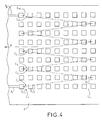
- la figure 4, une tête matricielle d'enregistrement/lecture selon l'invention ;
- la figure 5, un détail de tête élémentaire d'enregistrement/lecture applicable à la figure 4 ;
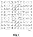
- la figure 6, une variante de tête matricielle selon l'invention ;
- la figure 7, une variante de réalisation d'une tête d'enregistrement/lecture selon l'invention.
- Figures 1 to 3, devices known in the art and described above;
- FIG. 4, a recording / reading matrix head according to the invention;
- FIG. 5, a detail of an elementary recording / playback head applicable to FIG. 4;
- FIG. 6, a variant of a matrix head according to the invention;
- Figure 7, an alternative embodiment of a recording / reading head according to the invention.
En se reportant à la figure 4, on va donc tout d'abord décrire un exemple de réalisation d'une tête matricielle d'enregistrement/lecture selon l'invention. Cette tête 1 comporte un ensemble d'éléments d'enregistrement/lecture arrangés en lignes et colonnes. La ligne L1 comporte les éléments E1.1 à Em.1 et la colonne C1 comporte les éléments E1.1 à E1.n. Selon un exemple de réalisation, un support d'enregistrement 2 est appelé à se déplacer selon une direction X de façon à enregistrer (ou lire) des pistes P1 à Pp. Les lignes, telle que L1, sont alors perpendiculaires ou sensiblement perpendiculaires à cette direction X. Les colonnes C1 à Cm forment un angle aigu avec la direction X. Deux colonnes voisines sont concourantes. Selon l'exemple de la figure 4, les colonnes de rangs impairs C1, C3, ... sont parallèles entre elles et les colonnes de rangs pairs C2, C4, ... sont parallèles entre elles. De plus, deux colonnes voisines sont symétriques par rapport à la direction X.Referring to Figure 4, we will therefore first describe an embodiment of a matrix recording / reading head according to the invention. This head 1 comprises a set of recording / reading elements arranged in rows and columns. Line L1 contains the elements E 1.1 to E m.1 and column C1 comprises the elements E 1.1 to E 1.n. According to an exemplary embodiment, a
Lorsque le support d'enregistrement 2 se déplace devant la tête d'enregistrement 1, l'élément ou tête élémentaire E1.1 parcourt la tête P1 et lit ou enregistre cette piste. L'élément E1.2 parcourt la piste P2, l'élément E1.n parcourt la piste Pn et l'élément Em.1, la piste Pm. Le nombre de pistes lues ou enregistrées est donc p = m.n.When the
Les éléments d'enregistrement/lecture peuvent être les entrefers de têtes magnétiques ou tout autre moyen capable d'enregistrer ou lire sur un support d'enregistrement.The recording / reading elements can be the air gaps of magnetic heads or any other means capable of recording or reading on a recording medium.
Selon la technique décrite en relation avec la figure 1, les pôles magnétiques situés de part et d'autre d'un entrefer peuvent avoir des longueurs différentes.According to the technique described in relation to Figure 1, the magnetic poles located on either side of an air gap can have different lengths.
Ainsi sur la figure 5, l'entrefer E1.1 est délimité par les pôles P1.1 et P'1.1, le pôle P1.1 étant plus court que le pôle P'1.1. Par contre l'entrefer E1.n est délimité par un pôle P1.n et par un pôle P'1.n qui est plus court que le pôle P1. Les longueurs des pôles varient graduellement le long d'une colonne d'une tête magnétique à la suivante entre une longueur maximale telle que celle de P'1.1 à une longueur minimale telle que celle de P1.1. Comme cela est représenté sur la figure 1, les pôles magnétiques sont couplés magnétiques à des plots magnétiques tels que 18' qui permettent de fermer les circuits magnétiques des têtes magnétiques par la plaque 10.Thus in FIG. 5, the air gap E 1.1 is delimited by the poles P 1.1 and P ' 1.1 , the pole P 1.1 being shorter than the pole P' 1.1 . On the other hand, the air gap E 1.n is delimited by a pole P 1.n and by a pole P ' 1.n which is shorter than the pole P 1 . The lengths of the poles gradually vary along a column from one magnetic head to the next between a maximum length such as that of P ' 1.1 to a minimum length such as that of P 1.1 . As shown in FIG. 1, the magnetic poles are magnetic coupled to magnetic pads such as 18 ′ which make it possible to close the magnetic circuits of the magnetic heads by the
Selon une variante de réalisation représentée en figure 7, et appliquant un mode de réalisation décrit dans le Brevet français, on prévoit un nombre inférieur de plots magnétiques comparés aux nombres de plots prévus dans la configuration de la figure 5. Pour cela, à chaque plot sont couplés magnétiquement quatre pôles au lieu de deux sur la figure 5. Le principe de longueurs différentes des pôles reste le même dans cette configuration.According to an alternative embodiment represented in FIG. 7, and applying an embodiment described in the French patent, a lower number of magnetic pads is provided compared to the numbers of pads provided in the configuration of FIG. 5. For this, at each pad four poles are magnetically coupled instead of two in FIG. 5. The principle of different lengths of the poles remains the same in this configuration.
Dans la configuration de la figure 4, on a deux têtes élémentaires côte à côte entre deux colonnes voisines. C'est le cas des têtes élémentaires E1.n et E2.n. Cela peut rendre difficile une bonne définition des pistes relatives à ces têtes en raison des limitations des procédés de gravure. La figure 6 fournit une variante qui résout ce problème. Dans cette variante, une tête élémentaire E12n par exemple, est commune à deux colonnes voisines.In the configuration of FIG. 4, there are two elementary heads side by side between two neighboring columns. This is the case of elementary heads E 1.n and 2.n E. This can make it difficult to properly define the tracks relating to these heads due to the limitations of the etching processes. FIG. 6 provides a variant which solves this problem. In this variant, an elementary head E12n for example, is common to two neighboring columns.
Ceci permet de constater que le fonctionnement du dispositif ne sera pas affecté par la disposition particulière des entrefers. En effet, chaque entrefer est situé sur une diagonale reliant deux plots magnétiques, au-dessus d'un -et d'un seul- croisement de fils d'excitation des lignes et des colonnes. Le fait qu'il ne soit pas au centre de ce motif ne modifie pas l'excitation magnétique qu'il reçoit, si la perméabilité du matériau constituant les pôles est suffisamment grande.This shows that the operation of the device will not be affected by the particular arrangement of the air gaps. Indeed, each air gap is located on a diagonal connecting two magnetic studs, above a - and a single - crossing of excitation wires of the rows and columns. The fact that it is not at the center of this pattern does not modify the magnetic excitation which it receives, if the permeability of the material constituting the poles is sufficiently high.
Les autres différences avec des réalisations actuellement connues sont les suivantes :
- le réseau de conducteurs et de rainures de lignes et de colonnes est ici rectangulaire, contrairement à des réalisations actuelles, où les lignes horizontales sont généralement disposées en oblique de manière à ce que les entrefers, qui sont disposées sur des lignes obliques afin d'écrire des pistes adjacentes, restent au centre de chaque motif.
- les lignes verticales d'entrefers ne sont pas situées au centre des rainures verticales, ce qui permet d'augmenter la distance entre pôles et plots de ferrite dans les colonnes extérieures de la tête.
- the network of conductors and grooves of lines and columns is here rectangular, unlike current embodiments, where the horizontal lines are generally arranged obliquely so that the air gaps, which are arranged on oblique lines in order to write adjacent tracks remain at the center of each pattern.
- the vertical air gap lines are not located in the center of the vertical grooves, which makes it possible to increase the distance between poles and ferrite studs in the outer columns of the head.
Claims (7)
Applications Claiming Priority (2)
| Application Number | Priority Date | Filing Date | Title |
|---|---|---|---|
| FR9506651A FR2735269B1 (en) | 1995-06-06 | 1995-06-06 | RECORDING HEAD / MATRIX PLAYBACK WITH ZIGZAG STRUCTURE |
| FR9506651 | 1995-06-06 |
Publications (2)
| Publication Number | Publication Date |
|---|---|
| EP0747889A1 true EP0747889A1 (en) | 1996-12-11 |
| EP0747889B1 EP0747889B1 (en) | 2001-06-20 |
Family
ID=9479666
Family Applications (1)
| Application Number | Title | Priority Date | Filing Date |
|---|---|---|---|
| EP96401139A Expired - Lifetime EP0747889B1 (en) | 1995-06-06 | 1996-05-28 | Matrix write/read head with zigzag structure |
Country Status (6)
| Country | Link |
|---|---|
| US (1) | US5920448A (en) |
| EP (1) | EP0747889B1 (en) |
| JP (1) | JPH08339506A (en) |
| KR (1) | KR970002884A (en) |
| DE (1) | DE69613431T2 (en) |
| FR (1) | FR2735269B1 (en) |
Families Citing this family (2)
| Publication number | Priority date | Publication date | Assignee | Title |
|---|---|---|---|---|
| ATE237177T1 (en) | 1999-07-09 | 2003-04-15 | Thales Sa | TRACKING SYSTEM FOR RECORDING/PLAYBACKING AN INFORMATION MEDIUM AND RECORDING MEDIUM |
| EP1498877A1 (en) * | 2003-07-15 | 2005-01-19 | O-Mass AS | Write head layout |
Citations (7)
| Publication number | Priority date | Publication date | Assignee | Title |
|---|---|---|---|---|
| DE1906358A1 (en) * | 1968-02-13 | 1969-08-21 | Ibm | Arrangement and method for producing an arrangement for switching on / off signal transmitters / receivers which are connected to the signal induction winding of a magnetic head by a selector circuit |
| NL7107030A (en) * | 1970-05-21 | 1971-11-23 | ||
| US4439793A (en) * | 1981-10-22 | 1984-03-27 | Fuji Photo Film Co., Ltd. | Thin film head array |
| EP0392906A1 (en) * | 1989-04-14 | 1990-10-17 | Thomson-Csf | Static magnetic read head |
| EP0409675A1 (en) * | 1989-07-21 | 1991-01-23 | Thomson-Csf | Multitrack magnetic head with high field contrast |
| US5124869A (en) * | 1988-04-27 | 1992-06-23 | Thomson-Csf | Matrix device with magnetic heads, notably in thin layers |
| US5212680A (en) * | 1991-10-10 | 1993-05-18 | International Business Machines Corporation | Mass storage device employing array of transducers "cocked" in relation to reciprocal movement axis |
Family Cites Families (11)
| Publication number | Priority date | Publication date | Assignee | Title |
|---|---|---|---|---|
| JPS54114220A (en) * | 1978-02-27 | 1979-09-06 | Olympus Optical Co Ltd | Magnetic head for plural channels |
| DE3063543D1 (en) * | 1979-12-04 | 1983-07-07 | Thomson Brandt | D.c. power supply generator and television receiver comprising such a generator |
| FR2473238A1 (en) * | 1980-01-08 | 1981-07-10 | Thomson Brandt | CONTROL CIRCUIT FOR SWITCH-MODE CIRCUIT, AND ESPECIALLY FOR FRAME SCANNING CIRCUIT OF A VIDEOFREQUENCY RECEIVER |
| US4539615A (en) * | 1981-06-08 | 1985-09-03 | Hitachi, Ltd. | Azimuthal magnetic recording and reproducing apparatus |
| FR2545307B1 (en) * | 1983-04-26 | 1986-03-21 | Thomson Brandt | APPARATUS FOR PROJECTING COLOR VIDEO IMAGES ON A LARGE SIZE SCREEN |
| FR2579051B1 (en) * | 1985-03-15 | 1988-06-24 | Loire Electronique | CONVERGENCE ADJUSTING DEVICE FOR VIDEO PROJECTOR |
| FR2639137B1 (en) * | 1988-11-15 | 1990-12-21 | Thomson Csf | MAGNETIC HEAD WITH SATURABLE GAP AND MATRIX DEVICE COMPRISING A SET OF SUCH HEADS |
| FR2648608B1 (en) * | 1989-06-16 | 1991-08-30 | Thomson Csf | MULTI-TRACK MAGNETIC RECORDING HEAD WITH COMPACT MATRIX STRUCTURE |
| FR2652670B1 (en) * | 1989-10-03 | 1995-06-23 | Thomson Csf | HIGH RESOLUTION MAGNETOOPTIC READING HEAD. |
| FR2665010B1 (en) * | 1990-07-20 | 1992-09-18 | Thomson Csf | MAGNETIC READING DEVICE WITH MATRIX NETWORK OF READING HEADS. |
| FR2683063B1 (en) * | 1991-10-29 | 1998-02-06 | Thomson Csf | METHOD FOR READING RECORDED INFORMATION AND READING SYSTEM. |
-
1995
- 1995-06-06 FR FR9506651A patent/FR2735269B1/en not_active Expired - Fee Related
-
1996
- 1996-05-28 EP EP96401139A patent/EP0747889B1/en not_active Expired - Lifetime
- 1996-05-28 DE DE69613431T patent/DE69613431T2/en not_active Expired - Lifetime
- 1996-06-03 JP JP8140253A patent/JPH08339506A/en active Pending
- 1996-06-05 KR KR1019960019902A patent/KR970002884A/en not_active Application Discontinuation
-
1997
- 1997-10-14 US US08/949,398 patent/US5920448A/en not_active Expired - Lifetime
Patent Citations (7)
| Publication number | Priority date | Publication date | Assignee | Title |
|---|---|---|---|---|
| DE1906358A1 (en) * | 1968-02-13 | 1969-08-21 | Ibm | Arrangement and method for producing an arrangement for switching on / off signal transmitters / receivers which are connected to the signal induction winding of a magnetic head by a selector circuit |
| NL7107030A (en) * | 1970-05-21 | 1971-11-23 | ||
| US4439793A (en) * | 1981-10-22 | 1984-03-27 | Fuji Photo Film Co., Ltd. | Thin film head array |
| US5124869A (en) * | 1988-04-27 | 1992-06-23 | Thomson-Csf | Matrix device with magnetic heads, notably in thin layers |
| EP0392906A1 (en) * | 1989-04-14 | 1990-10-17 | Thomson-Csf | Static magnetic read head |
| EP0409675A1 (en) * | 1989-07-21 | 1991-01-23 | Thomson-Csf | Multitrack magnetic head with high field contrast |
| US5212680A (en) * | 1991-10-10 | 1993-05-18 | International Business Machines Corporation | Mass storage device employing array of transducers "cocked" in relation to reciprocal movement axis |
Non-Patent Citations (1)
| Title |
|---|
| "COMPACT HORIZONTAL HEAD STRUCTURE FOR ARRAYS", IBM TECHNICAL DISCLOSURE BULLETIN, vol. 36, no. 5, 1 May 1993 (1993-05-01), pages 377/378, XP000409027 * |
Also Published As
| Publication number | Publication date |
|---|---|
| US5920448A (en) | 1999-07-06 |
| FR2735269A1 (en) | 1996-12-13 |
| DE69613431T2 (en) | 2002-06-06 |
| FR2735269B1 (en) | 1997-07-25 |
| JPH08339506A (en) | 1996-12-24 |
| EP0747889B1 (en) | 2001-06-20 |
| KR970002884A (en) | 1997-01-28 |
| DE69613431D1 (en) | 2001-07-26 |
Similar Documents
| Publication | Publication Date | Title |
|---|---|---|
| CN101162585B (en) | Magnetic head and magnetic tape drive system | |
| US4439793A (en) | Thin film head array | |
| CN101256780B (en) | Patterned magnetic recording medium and magnetic recording system incorporating the medium | |
| EP0694912B1 (en) | Magnetic circuits for recording/reproducing magnetic head arrangement | |
| KR940012244A (en) | Dual element magnetoresistance sensing heads and read / write magnetic heads with sensing sense heads | |
| KR950030051A (en) | Magnetoresistive (MR) read transducer with thermal noise canceling means and disk drive including the transducer | |
| KR20090025954A (en) | Bit patterned media with a super track, reading head and hard disk drive for recording/reading data on/from the bit patterned media | |
| FR2519175A1 (en) | ROTATING HEAD UNIT | |
| EP0747889B1 (en) | Matrix write/read head with zigzag structure | |
| EP0061363A1 (en) | High-density information magnetoresistive read transducer | |
| EP0409675B1 (en) | Multitrack magnetic head with high field contrast | |
| US20050013042A1 (en) | Write head layout | |
| JP4151623B2 (en) | Magnetic head device and magnetic recording device | |
| US7012786B2 (en) | Magnetic head | |
| JPH0443338B2 (en) | ||
| JP2956796B2 (en) | Magnetic disk drive | |
| JPS58203620A (en) | Data surface servo system | |
| Coutellier et al. | A 384 track fixed recording head | |
| JP3361345B2 (en) | Magnetic recording device | |
| Coutellier et al. | Towards a 1000 tracks digital tape recorder | |
| EP0652549B1 (en) | Magnetic recording/reading head | |
| JPH01217718A (en) | Thin film multiple magnetic head | |
| FR2723243A1 (en) | DEVICE FOR RECORDING AND / OR PLAYING MAGNETIC HEADS AND ITS MANUFACTURING METHOD | |
| JP2000339638A (en) | Thin-film magnetic head and its slider as well as magnetic recording and reproducing device | |
| JPS62185217A (en) | Thin film magnetic head |
Legal Events
| Date | Code | Title | Description |
|---|---|---|---|
| PUAI | Public reference made under article 153(3) epc to a published international application that has entered the european phase |
Free format text: ORIGINAL CODE: 0009012 |
|
| AK | Designated contracting states |
Kind code of ref document: A1 Designated state(s): DE GB IT NL |
|
| 17P | Request for examination filed |
Effective date: 19970210 |
|
| GRAG | Despatch of communication of intention to grant |
Free format text: ORIGINAL CODE: EPIDOS AGRA |
|
| GRAG | Despatch of communication of intention to grant |
Free format text: ORIGINAL CODE: EPIDOS AGRA |
|
| GRAG | Despatch of communication of intention to grant |
Free format text: ORIGINAL CODE: EPIDOS AGRA |
|
| 17Q | First examination report despatched |
Effective date: 20000807 |
|
| GRAG | Despatch of communication of intention to grant |
Free format text: ORIGINAL CODE: EPIDOS AGRA |
|
| GRAH | Despatch of communication of intention to grant a patent |
Free format text: ORIGINAL CODE: EPIDOS IGRA |
|
| GRAH | Despatch of communication of intention to grant a patent |
Free format text: ORIGINAL CODE: EPIDOS IGRA |
|
| GRAA | (expected) grant |
Free format text: ORIGINAL CODE: 0009210 |
|
| AK | Designated contracting states |
Kind code of ref document: B1 Designated state(s): DE GB IT NL |
|
| REF | Corresponds to: |
Ref document number: 69613431 Country of ref document: DE Date of ref document: 20010726 |
|
| ITF | It: translation for a ep patent filed |
Owner name: JACOBACCI & PERANI S.P.A. |
|
| GBT | Gb: translation of ep patent filed (gb section 77(6)(a)/1977) |
Effective date: 20010907 |
|
| RAP2 | Party data changed (patent owner data changed or rights of a patent transferred) |
Owner name: THALES |
|
| NLT2 | Nl: modifications (of names), taken from the european patent patent bulletin |
Owner name: THALES |
|
| REG | Reference to a national code |
Ref country code: GB Ref legal event code: IF02 |
|
| PLBE | No opposition filed within time limit |
Free format text: ORIGINAL CODE: 0009261 |
|
| STAA | Information on the status of an ep patent application or granted ep patent |
Free format text: STATUS: NO OPPOSITION FILED WITHIN TIME LIMIT |
|
| 26N | No opposition filed | ||
| PGFP | Annual fee paid to national office [announced via postgrant information from national office to epo] |
Ref country code: NL Payment date: 20040505 Year of fee payment: 9 |
|
| PG25 | Lapsed in a contracting state [announced via postgrant information from national office to epo] |
Ref country code: NL Free format text: LAPSE BECAUSE OF NON-PAYMENT OF DUE FEES Effective date: 20051201 |
|
| NLV4 | Nl: lapsed or anulled due to non-payment of the annual fee |
Effective date: 20051201 |
|
| PGFP | Annual fee paid to national office [announced via postgrant information from national office to epo] |
Ref country code: IT Payment date: 20090520 Year of fee payment: 14 |
|
| REG | Reference to a national code |
Ref country code: GB Ref legal event code: 732E Free format text: REGISTERED BETWEEN 20100408 AND 20100414 |
|
| PG25 | Lapsed in a contracting state [announced via postgrant information from national office to epo] |
Ref country code: IT Free format text: LAPSE BECAUSE OF NON-PAYMENT OF DUE FEES Effective date: 20100528 |
|
| PGFP | Annual fee paid to national office [announced via postgrant information from national office to epo] |
Ref country code: DE Payment date: 20120531 Year of fee payment: 17 |
|
| PGFP | Annual fee paid to national office [announced via postgrant information from national office to epo] |
Ref country code: GB Payment date: 20120426 Year of fee payment: 17 |
|
| GBPC | Gb: european patent ceased through non-payment of renewal fee |
Effective date: 20130528 |
|
| PG25 | Lapsed in a contracting state [announced via postgrant information from national office to epo] |
Ref country code: DE Free format text: LAPSE BECAUSE OF NON-PAYMENT OF DUE FEES Effective date: 20131203 |
|
| REG | Reference to a national code |
Ref country code: DE Ref legal event code: R119 Ref document number: 69613431 Country of ref document: DE Effective date: 20131203 |
|
| PG25 | Lapsed in a contracting state [announced via postgrant information from national office to epo] |
Ref country code: GB Free format text: LAPSE BECAUSE OF NON-PAYMENT OF DUE FEES Effective date: 20130528 |