EP0780665A2 - Processor apparatus and method for a process measurement signal - Google Patents
Processor apparatus and method for a process measurement signal Download PDFInfo
- Publication number
- EP0780665A2 EP0780665A2 EP96120455A EP96120455A EP0780665A2 EP 0780665 A2 EP0780665 A2 EP 0780665A2 EP 96120455 A EP96120455 A EP 96120455A EP 96120455 A EP96120455 A EP 96120455A EP 0780665 A2 EP0780665 A2 EP 0780665A2
- Authority
- EP
- European Patent Office
- Prior art keywords
- signal
- tdr
- output result
- calculating
- reflection
- Prior art date
- Legal status (The legal status is an assumption and is not a legal conclusion. Google has not performed a legal analysis and makes no representation as to the accuracy of the status listed.)
- Withdrawn
Links
Images


Classifications
-
- G—PHYSICS
- G01—MEASURING; TESTING
- G01F—MEASURING VOLUME, VOLUME FLOW, MASS FLOW OR LIQUID LEVEL; METERING BY VOLUME
- G01F23/00—Indicating or measuring liquid level or level of fluent solid material, e.g. indicating in terms of volume or indicating by means of an alarm
- G01F23/22—Indicating or measuring liquid level or level of fluent solid material, e.g. indicating in terms of volume or indicating by means of an alarm by measuring physical variables, other than linear dimensions, pressure or weight, dependent on the level to be measured, e.g. by difference of heat transfer of steam or water
- G01F23/28—Indicating or measuring liquid level or level of fluent solid material, e.g. indicating in terms of volume or indicating by means of an alarm by measuring physical variables, other than linear dimensions, pressure or weight, dependent on the level to be measured, e.g. by difference of heat transfer of steam or water by measuring the variations of parameters of electromagnetic or acoustic waves applied directly to the liquid or fluent solid material
- G01F23/284—Electromagnetic waves
-
- G—PHYSICS
- G01—MEASURING; TESTING
- G01F—MEASURING VOLUME, VOLUME FLOW, MASS FLOW OR LIQUID LEVEL; METERING BY VOLUME
- G01F23/00—Indicating or measuring liquid level or level of fluent solid material, e.g. indicating in terms of volume or indicating by means of an alarm
- G01F23/22—Indicating or measuring liquid level or level of fluent solid material, e.g. indicating in terms of volume or indicating by means of an alarm by measuring physical variables, other than linear dimensions, pressure or weight, dependent on the level to be measured, e.g. by difference of heat transfer of steam or water
- G01F23/28—Indicating or measuring liquid level or level of fluent solid material, e.g. indicating in terms of volume or indicating by means of an alarm by measuring physical variables, other than linear dimensions, pressure or weight, dependent on the level to be measured, e.g. by difference of heat transfer of steam or water by measuring the variations of parameters of electromagnetic or acoustic waves applied directly to the liquid or fluent solid material
- G01F23/296—Acoustic waves
- G01F23/2962—Measuring transit time of reflected waves
Definitions
- the present invention relates to a processor apparatus and method for a process measurement signal. More particularly, the present invention relates to an improved processor for time-of-flight signals to provide an accurate indication of the location of an interface between a first medium and a second medium in a vessel.
- the value of the measured materials is high enough to justify high cost level measurement systems which are required for the extreme accuracy needed.
- Such expensive measurement systems can include a servo tank gauging system or a frequency modulated continuous wave radar system.
- Ultrasonic time-of-flight technology has reduced concerns regarding level indications changing as material characteristics change.
- ultrasonic level measurement sensors cannot work under high temperatures, high pressures, or in vacuums.
- ultrasonic sensors have a low tolerance for acoustic noise.
- a sensor apparatus must be provided for transmitting these low power, high frequency pulses down a probe and effecting their return.
- Such appropriate sensor apparatus is described in a copending U.S. Patent Application Serial No. 08,574,818, entitled SENSOR APPARATUS FOR PROCESS MEASUREMENT, filed December 19, 1995 and a copending U.S. Patent Application Serial No. 08/735,736 entitled SENSOR APPARATUS FOR PROCESS MEASUREMENT, filed October 23, 1996, the disclosures of which are hereby expressly incorporated by reference into the present application.
- the sensor apparatus is particularly adapted for the measurement of material levels in process vessels and storage vessels, but is not limited thereto. It is understood that the sensor apparatus may be used for measurement of other process variables such as flow, composition, dielectric constant, moisture content, etc.
- the term "vessel” refers to pipes, chutes, bins, tanks, reservoirs or any other storage vessels. Such storage vessels may also include fuel tanks, and a host of automotive or vehicular fluid storage systems or reservoirs for engine oil, hydraulic fluids, brake fluids, wiper fluids, coolant, power steering fluid, transmission fluid, and fuel.
- the present invention propagates electromagnetic energy down an inexpensive, signal conductor transmission line as an alternative to conventional coax cable or dual transmission lines.
- the Goubau line lends itself to applications for a level measurement sensor where an economical rod or cable probe (i.e. , a one conductor instead of a twin or dual conductor approach) is desired.
- the single conductor approach enables not only taking advantage of new pulse generation and detection technologies, but also constructing probes in a manner similar to economical capacitance level probes.
- the present invention specifically relates to a signal processor apparatus for processing and interpreting the returned pulses from the conductor. Due to the low power, broadband pulses used in accordance with the present invention, such signal processing to provide a meaningful indication of the process variable is difficult. Conventional signal processing techniques use only simple peak detection to monitor reflections of the pulses.
- the present invention provides signal processing circuitry configured for measurement of the time-of-flight of very fast, guided wave pulses.
- Techniques used in similar processes, such as ultrasonic level measurement are vastly different from and are insufficient for detection of guided electromagnetic wave pulses due to the differences in signal characteristics.
- ultrasonic signals are much noisier and have large dynamic ranges of about 120 dB and higher.
- Guided electromagnetic waves in this context are low in noise and have low dynamic ranges (less than 10:1) compared to the ultrasonic signals, and are modified by environmental impedances.
- the signal processor of the present invention is configured to determine an appropriate reflection pulse of these low power signals from surrounding environmental influences.
- TDR devices for level measurement require the measuring of the time of flight of a transit pulse and a subsequently produced reflective pulse received at the launching site of the transit pulse. This measurement is typically accomplished by determining the time interval between the maximum amplitude of the received pulse. The determination of this time interval is done by counting the interval between the transmitted pulse and the received pulse.
- the present invention provides an improved signal processor for determining a valid reflective pulse signal caused by an interface of material in contact with a probe element of a sensor apparatus.
- the processor apparatus of the present invention is particularly useful for processing high speed, low power pulses as discussed above.
- processing is performed based on a digital sampling of an analog output of the reflective pulses. It is understood, however, that similar signal processing techniques can be used on the analog signal in real time.
- the present invention provides a processing means and method for compensating for signal drifts caused by these operating conditions.
- a method for processing a time domain reflectometry (TDR) signal to generate an output result corresponding to a valid process variable.
- the method includes the steps of processing the TDR signal using at least two different techniques for detecting a valid reflection pulse generated by the process variable to calculate an independent result using each of the at least two techniques, and applying a weighted factor to the independent results from each of the at least two different techniques to provide weighted output results.
- the method also includes the steps of comparing the weighted output results, and selecting the valid output result from the weighted output results based on the comparing step.
- the comparing step includes the step of summing the weighted factors for each independent result.
- a method for processing a time domain reflectometry (TDR) signal having a plurality of reflection pulses to generate a valid output result corresponding to a reflection pulse caused by a process variable.
- the method includes the steps of processing the TDR signal using a first method for detecting the reflection pulse generated by the process variable and for calculating a first output result, processing the TDR signal using a second method for detecting the reflection pulse generated by the process variable and for calculating a second output result, and processing the TDR signal using a third method for detecting the reflection pulse generated by the process variable and for calculating a third output result.
- the method also includes the steps of comparing the first, second, and third results, and selecting the valid output result based on the comparing step.
- the comparing step includes the step of applying a weighted factor to each of the first, second, and third results prior to the selecting step.
- the comparing step also includes the step of summing the weighted factors for each of the first, second, and third results.
- the first processing method includes the steps of detecting a maximum value reflection pulse from the plurality of reflection pulses of the TDR signal and calculating the first result based on the maximum value reflection pulse of the TDR signal.
- the second processing method includes the steps of calculating a derivative of the TDR signal, determining a location of a zero crossing adjacent an absolute maximum value of the derivative TDR signal, and calculating the second result based on said zero crossing.
- the third processing method includes the steps of establishing an initial boundary reflection signal, determining a baseline signal by subtracting the initial boundary signal from the TDR signal, determining a maximum value reflection pulse of the baseline signal, and calculating the third result based on the maximum value reflection pulse of the baseline signal.
- the method further includes the step of processing the TDR signal using a fourth method for detecting the reflection pulse generated by the Process variable and for calculating a fourth output result.
- the comparing step compares the first, second, third, and fourth results.
- the comparing step includes the step of applying a weighted factor to each of the first, second, third, and fourth results prior to the selecting step.
- the fourth processing method illustratively includes the steps of calculating a derivative of the baseline signal, determining a time position of a zero crossing adjacent an absolute maximum of the derivative of the baseline signal, and calculating the fourth result based on the zero crossing adjacent the absolute maximum of the derivative of the baseline signal.
- a method for processing a time domain reflectometry (TDR) signal having a plurality of reflection pulses to generate a valid output result corresponding to a reflection pulse caused by a process variable in a vessel.
- the TDR signal is generated by a sensor apparatus.
- the method includes the steps of establishing an initial boundary signal for the sensor apparatus before the process variable is located in the vessel, and storing the detected initial boundary signal.
- the method also includes the steps of detecting the TDR signal, detecting a maximum value reflection pulse from the plurality of reflection pulses of the TDR signal, and calculating a first output result based on the maximum value reflection pulse of the TDR signal.
- the method further includes the steps of calculating a derivative of the TDR signal, determining a location of a zero crossing adjacent an absolute maximum value of the derivative TDR signal, calculating a second output result based on the zero crossing adjacent an absolute maximum value of the derivative TDR signal.
- the method still further includes the steps of determining a baseline signal by subtracting the initial boundary signal from the TDR signal, determining a maximum value of the baseline signal, and calculating a third output result based on the maximum value of the baseline signal.
- the method includes the steps of calculating a derivative of the baseline signal, determining a time position of a zero crossing adjacent an absolute maximum of the derivative of the baseline signal, and calculating a fourth output result based on the zero crossing adjacent the absolute maximum of the derivative of the baseline signal.
- the method also includes the steps of comparing the first, second, third, and fourth output results, and selecting the valid output result from the weighted output results based on the comparing step.
- the comparing step includes the step of applying weighted factors to the first, second, third, and fourth results to produce weighted results.
- the comparing step also includes the step of selecting the valid output result from the weighted results.
- the illustrated method also includes the step of establishing a new initial boundary reflection signal at a selected time, and storing the new initial boundary signal to update the baseline signal.
- the comparing step may include the steps of comparing the first, second, and third results to a previous output result, and disregarding a particular result which deviates from the previous output result by more than a selected amount.
- a method for processing a time domain reflectometry (TDR) signal having a plurality of reflection pulses to generate a valid output result corresponding to a reflection pulse caused by a process variable.
- the method includes the steps of processing the TDR signal using a primary detection method for detecting the reflection pulse generated by the process variable and for calculating a primary output result, and processing the TDR signal using at least one secondary method for detecting the reflection pulse generated by the process variable and for calculating at least one secondary output result.
- the method also includes the steps of comparing the primary result to the at least one secondary result to check the primary result, and selecting the valid output result based on the comparing step.
- the comparing step includes the step of applying a weighted factor to the primary result and each of the secondary results prior to the selecting step.
- an apparatus for processing a time domain reflectometry (TDR) signal having a plurality of reflection pulses to generate a valid output result corresponding to a reflection pulse caused by a process variable.
- the apparatus includes means for processing the TDR signal using a first method for detecting the reflection pulse generated by the process variable and for calculating a first output result, for processing the TDR signal using a second method for detecting the reflection pulse generated by the process variable and for calculating a second output result, and for processing the TDR signal using a third method for detecting the refleciton pulse generated by the process variable and for calculating a third output result, means for comparing the first, second, and third results, and means for selecting the valid output result.
- TDR time domain reflectometry
- the apparatus further includes means for processing the TDR signal using a fourth method for detecting the reflection pulse generated by the process variable and for calculating a fourth output result.
- the comparing means compares the first, second, third, and fourth results.
- the comparing means illustratively includes means for applying a weighted factor to each of the first, second, third, and fourth results.
- an apparatus for processing a time domain reflectometry (TDR) signal having a plurality of reflection pulses to generate a valid output result corresponding to a refleciton pulse caused by a process variable.
- the apparatus includes means for processing the TDR signal using a primary detection method for detecting the reflection pulse generated by the process variable and for calculating a primary output result, for processing the TDR signal using at least one secondary method for detecting the reflection pulse generated by the process variable and for calculating at least one secondary output result, for comparing the primary result to the at least one secondary result to check the primary result, and for selecting the valid output result based on the comparison.
- the comparing means includes means for applying a weighted factor to the primary result and each of the secondary results.
- a method for processing a time domain reflectometry (TDR) signal to generate a valid output result corresponding to a process variable in a vessel.
- the method includes the steps of establishing an initial boundary signal before the process variable is located in the vessel; storing the initial boundary signal and detecting a TDR signal.
- the method also includes the steps of determining a baseline signal by subtracting the initial boundary signal from the TDR signal, establishing a signal pattern having a time range based on the width of reflection pulses in the baseline signal and comparing the baseline signal to the signal pattern until a reflection pulse in the baseline signal matches the signal pattern.
- a method for processing a time domain reflectometry (TDR) signal to generate a valid output result corresponding to a process variable in a vessel includes the steps of establishing an initial boundary signal before the process variable is located in the vessel, storing the initial boundary signal, and detecting the TDR signal.
- the method further includes the steps of determining a point on the initial boundary signal and a corresponding point on the TDR signal, calculating a correction factor by subtracting the point on the initial boundary signal from the corresponding point on the TDR signal, and adding the correction factor to the TDR signal to establish a valid TDR signal.
- the method further includes the step of determining a baseline signal by subtracting the initial boundary signal from the valid TDR signal.
- the first processing method includes the steps of establishing a threshold voltage prior to comparing the baseline signal to the signal pattern and converting negative-going components of the reflection pulses to positive-going components. Further, in the first processing method the step of establishing a signal pattern includes the step of determining at least four points within the time range in proximity to the threshold voltage and the step of comparing the baseline signal to the signal pattern includes the step of searching for a reflection pulse where the four points are on the reflection pulse in proximity to the threshold voltage.
- the second processing method includes the step of converting the correction factor to a positive value prior to adding the correction factor to the TDR signal to establish the valid TDR signal.
- the processing methods include the steps of determining a maximum value of the baseline signal and calculating an output result based on the maximum value.
- an apparatus for processing a time domain reflectometry (TDR) signal having a plurality of reflection pulses to generate a valid output result corresponding to a process variable in a vessel.
- the apparatus includes means for establishing an initial boundary signal before the process variable is located in the vessel, means for storing the initial boundary signal, means for detecting the TDR signal, and means for determining a baseline signal by subtracting the initial boundary signal from the TDR signal.
- the apparatus further includes means for establishing a signal pattern having a time range based on the width of reflection pulses in the baseline signal and means for comparing the baseline signal to the signal pattern until a reflection pulse in the baseline signal matches the signal pattern.
- an apparatus for processing a time domain reflectometry (TDR) signal having a plurality of reflection pulses to generate a valid output results corresponding to a process variable in a vessel.
- the apparatus includes means for establishing an initial boundary signal before the process variable is located in the vessel, means for storing the initial boundary signal, and means for detecting the TDR signal.
- the apparatus further includes means for determining a point on the initial boundary signal and a corresponding point on the TDR signal, means for calculating a correction factor by subtracting the point on the initial boundary signal from the corresponding point on the TDR signal, means for adding the correction factor to the TDR signal to establish a valid TDR signal, and means for determining a baseline signal by subtracting the initial boundary signal from the valid TDR signal.
- the illustrated embodiments of the apparatus also include means for determining a maximum value of the baseline signal and means for calculating an output result based on the maximum value.
- Fig. 1 provides a diagrammatical illustration of operation of the surface wave transmission line sensor apparatus for process measurement.
- the apparatus 10 is adapted for use with level measurement of a process variable such as an interface between a first medium 11 and a second medium 12 located within a storage vessel 14.
- a process variable such as an interface between a first medium 11 and a second medium 12 located within a storage vessel 14.
- the first medium 11 is air and the second medium 12 is a process variable such as a liquid or other material.
- the present invention includes a mechanical mounting apparatus 16 for securing a single conductor transmission line or probe element 18 to a surface 20 of the vessel 14.
- the mechanical mounting apparatus 16 enables a transceiver 22 to transmit pulses onto the probe element 18 in the direction of arrow 24. Once the pulses reach an interface 26 between the first medium 11 and the second medium 12, such as a top surface of liquid, a reflective pulse is returned back up the probe element 18 in the direction of arrow 28.
- the transceiver 22 is coupled to processing circuitry which detects the reflected pulses to interpret the return pulses and to generate an output signal indicating the level of second medium 12 in the vessel 14.
- the transceiver 22 transmits broadband pulses at very low average power levels such as about 1nW or less, or 1 ⁇ W or less peak power.
- the frequency of the pulses is preferably about 100 MHz or greater.
- the transceiver 22 includes a transmit pulse generator 30 which generates a series of the high frequency pulses and transmits these pulses via a cable 32 to mounting 16.
- Transceiver 22 also includes a sequential delay generator 32 coupled to the transmit pulse generator 30.
- a sample pulse generator 34 is coupled to the sequential delay generator 32.
- a sample and hold buffer 36 is coupled to sample pulse generator 34 and to the cable 37.
- transceiver 22 is a micropower wide band impulse radar transmitter developed by the Lawrence Livermore National Laboratory located at the University of California located in Livermore, California. It is understood, however, that other transceivers 22 may also be used with the signal processor apparatus of the present invention.
- the mounting apparatus 16 must be specially designed to transmit and receive the low power, high frequency pulses.
- the above-referenced copending applications the disclosures of which are expressly incorporated by reference, provide a suitable mounting apparatus 16 for transceiver 22. It is understood that the electronics and processing circuitry may be located at a remote mounting location spaced apart from the mounting apparatus 16.
- An output from transceiver 22 on line 38 is coupled to an amplifier 40.
- An output from amplifier 40 provides a TDR analog signal on line 42.
- the preferred embodiment of the present invention uses a digital sampling system and processes digital signals related to the analog output signals, it is understood that a processor apparatus in accordance with the present invention may be built to process the analog signal directly.
- an analog-to-digital converter 44 is coupled to amplifier 40.
- An output of the analog-to-digital converter 44 is coupled to an input of microprocessor 46.
- microprocessor 46 is a MC68HC711E9 microprocessor available from Motorola. It is understood, however, that any other suitable microprocessor may be used in accordance with present invention.
- Microprocessor 46 is used to implement both a fast clock and a slow clock.
- a PRF clock implemented by microprocessor 46 which is a square wave at about 2 MHz, is coupled to transmit pulse generator 30.
- the microprocessor 46 also implements a sync oscillator, which is illustratively a square wave having a frequency of about 40 Hz. The sync oscillator is coupled to sequential delay generator 32.
- Microprocessor 46 is also coupled to RAM 48 and to EEPROM 50. An output terminal of microprocessor 46 is coupled to an output 52. Illustratively, output 52 provides a 4-20 mA output signal to provide an indication of the level of the interface 26 between the first medium 11 and the second medium 12.
- the TDR analog signal from amplifier 40 is an equivalent time signal (ETS) of the real time signal traveling on the transmission line system.
- ETS equivalent time signal
- the signal processor of the present invention provides means for determining a valid pulse reflection, whether in real time or from the ETS. These results allow flexibility to determine information relating to the position of mediums 11 and 12 relative to a top surface 20, a bottom surface 21, a sensor launch plate, or an end 19 of the probe element 18.
- the process material positional information is derived from signal reflections caused by impedance discontinuities on the transmission line and subsequent signal processing.
- the signal responses of a transmission line which includes cable 32, mounting 16, and probe element 18 are dependent upon the inherent transmission design characteristics and impedance changes created by changing boundary conditions. These boundary conditions are used to determine changes in the sensor environment and are directly or indirectly related to the amount or position of the bulk process materials being measured.
- the impedance of the sensor at a given location can change with variations of the sensor s environment or boundary condition due to interaction of the sensor, its signal, and its surroundings.
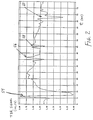
- FIG. 2 An example of a time domain reflectometry (TDR) analog signal from amplifier 40 is illustrated in Fig. 2.
- TDR time domain reflectometry
- the first large voltage fluctuation or pulse 54 is generated by the impedance change in the mounting 16.
- the mounting 16 provides this impedance change as a reference reflective pulse.
- the second reflective pulse 56 in Fig. 2 is generated by an inherent interference within vessel 14. This interference reflection 56 may be caused by a ladder, door, weld seam, material buildup, or other internal factor from vessel 14.
- the third reflective pulse 58 is provided by the interface 26 between the first medium 11 and the second medium 12.
- the fourth reflective pulse 60 is generated by an end 19 of probe element 18.
- the present invention initializes the signal processing function by characterizing or recording sensor performance at a given time or under known boundary conditions so that this initial characterization can be used as an initial boundary condition.
- a reference or initial boundary signal is measured and stored before the first and second mediums 11 and 12 are placed in the vessel 14.
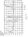
- FIG. 3 An example of an initial boundary signal (I.B.) is illustrated in Fig. 3.
- the initial boundary signal is used to help determine a valid impedance change induced reflective pulse caused by interface 26 between first medium 11 and second medium 12.
- the initial voltage peak or reflective pulse 62 is caused by the interference in the vessel 14.
- Pulse 62 of Fig. 3 corresponds to pulse 56 in Fig. 2.
- Pulse 64 in Fig. 3 corresponds to the end 19 of probe element 18.
- the sensor characterization may include factory calibration, environmental characterization or probe mapping, and sensor recharacterization, or recalibration.
- the characterization can be done in such a way to permit use of only one or a combination of initialization procedures to provide optimum performance.
- the characterization of the sensor and its signals inside or outside of its installation environment such as the mounting in the vessel 14 are referred to as its initial boundary conditions.
- Factory calibration may include characterizing sensor performance in a stable, known environment which provides a baseline for the system performance while neglecting the influences and effects that are encountered in field installation.
- a field installation such as mounting the sensor in a tank or vessel 14, can present an environment for new boundary conditions to the sensor caused by the vessel or permanent contents of the vessel which influence the sensor response due to interaction of the sensor with these vessel contents.
- the present invention provides either an automatic recharacterization or a manual recharacterization of the sensor which can be performed to re-establish a new baseline or probe map which enables these environmental changes to be accounted for in determining the valid signal indicating the desired process variable.
- a second phase of the signal processor of the present invention involves detecting the pulse reflection produced by a valid signal response of the impedance change along a conductor.
- the processor apparatus locates the impedance pulse reflection caused by the interface 26 between the first medium 11 and the second medium 12 in contact with the probe element 18.
- a number of mathematical techniques can be used to determine the positional information due to impedance changes which generate a signal reflection related in time to the position of the cause of the impedance change along the probe element 18.
- Detection of impedance changes may include one or more of the following techniques applied to the TDR analog output signal illustrated in Fig. 2.
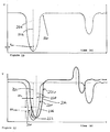
- One detection method is a peak amplitude detection of a Time Aligned TDR signal which is illustrated in Fig. 4.
- the signal of Fig. 4 is shifted so that time zero is set as the time of the initial reflecting pulse 54 provided by the impedance change at the mounting 16.
- the first reflection pulse 66 is caused by the interference within vessel 14.
- Second reflection pulse 68 is caused by interface 26.
- the third reflection pulse 70 is caused by end 19 of the probe element 18.
- Another detection technique is to determine the first zero crossing after the positive peak of a first derivative signal of the Time Aligned TDR signal of Fig. 4. This derivative signal is illustrated in Fig. 5.
- the first reflection pulse 72 is caused by the interference within vessel 14.
- the second reflection pulse 74 is caused by interface 26, and the third reflection pulse 76 is caused by end 19 of probe element 18.
- the processor apparatus determines the maximum absolute value of the peak reflective pulse, which is illustratively at location 78. If the absolute maximum was a negative value, the preceding zero crossing at location 80 is determined to be the location of interface 26. If the absolute maximum was a positive peak, the next subsequent zero crossing is used as the indication of interface 26.
- a baseline signal is illustrated in Fig. 6.
- the baseline signal is determined by subtracting the initial boundary signal of Fig. 3 from the Time Aligned TDR signal of Fig. 4. Therefore, the pulse reflection 66 caused by the interference within vessel 14 is cancelled by the initial boundary pulse reflection 62.
- the initial pulse reflection 82 is therefore caused by the interface 26 between the first medium 11 and the second medium 12.
- Reflective pulse 84 is caused by the end 19 of probe element 18.
- the processor determines the time of the greatest positive peak 86 as the pulse reflection caused by interface 26.
- Still another technique for determining the actual position of interface 26 is to use the first derivative signal of the baseline signal of Fig. 6.
- the derivative of the baseline signal is illustrated in Fig. 7.
- the first reflection pulse 88 is caused by the interface 26 between first medium 11 and second medium 12.
- the second reflection pulse 90 is caused by end 19 of probe element 18.
- the processor determines the peak absolute value 92 of the pulse reflection 88. Since the peak absolute value is associated with a negative voltage, the processor proceeds to the first proceeding zero crossing 94 as the time for the interface 26. If the maximum absolute value was a positive peak, the next subsequent zero crossing is used as the interface level.
- Some embodiments of the present invention use a combination of two or more of the above-cited techniques to verify the data related to the valid detection of interface 26.
- the short term history of the signal can also be used to substantiate the validity of any change in position of the interface 26 and to verify that this change is possible within the process condition presently being used in the vicinity of the sensor.
- the processor determines the location of the valid impedance discontinuity caused by interface 26 between first medium 11 and second medium 12 using each of the four techniques or methods discussed above. Each method is assigned a weighted factor.
- the baseline signal calculation illustrated in Fig. 6 is assigned a weighted factor of 1.1, while the other three techniques are assigned a weighted factor of 1.0.
- These weighted factors provide means for showing the degree of agreement among the four methods. If the calculated boundary conditions as detected by the sensor creates a conflict among the four detection methods such that there is not a substantial agreement of all four methods, then a valid result is dependent upon whether there is substantial agreement between two or three of the detection methods. If there is substantial deviation in the detection of the valid impedance pulse by all four methods, then the method having the highest weighted factor is used as the valid detection.
- the microprocessor 46 is programmed with software to calculate the position of the valid impedance change caused by interface 26 using each of the four methods discussed above.
- Fig. 8 illustrates the steps performed by the microprocessor 46 of the present invention to determine the valid signal.
- the microprocessor 46 is first initialized as illustrated at block 100. Operation mode of the signal processor is illustrated at block 102.
- the first operational mode is to set and store the initial boundary (I.B.) signal illustrated in Fig. 3.
- This initial boundary signal is generated before the process material is placed in vessel 14.
- Microprocessor 46 first receives an input initial boundary signal as illustrated at block 104. The data is then time aligned based on the initial impedance change caused by the mounting 16 as illustrated as block 106. Microprocessor 46 then stores the time aligned data related to the initial boundary conditions in the EEPROM 50 as illustrated at block 108. Once the initial boundary signal is stored, microprocessor 46 returns to operation mode at block 102.
- the signal processor of the present invention may establish the initial boundary conditions manually only during initial installation of the sensor apparatus 10 into the vessel 14. In another instance, the initial boundary conditions may be updated at predetermined times during operation of the signal processor.
- microprocessor 46 receives an input TDR signal as illustrated at block 110.
- This input TDR signal is a digital representation from analog-to-digital converter 44 of the TDR analog signal illustrated in Fig. 2.
- analog-to-digital converter 44 of the TDR analog signal illustrated in Fig. 2.
- the microprocessor 46 of the present invention uses the digital representation of these signals. It is also understood that an analog processor may be used to process the analog signals in accordance with the present invention.
- Microprocessor 46 next provides a time alignment of the TDR signal as illustrated at block 112. In other words, microprocessor 46 time shifts the input TDR signal so that the time zero begins at the location of the interface of mounting 16 which is indicated by the initial large reflection pulse 54 shown in Fig. 2.
- microprocessor 46 uses four different detection methods to locate a valid pulse reflection indicative of the interface 26 between the first medium 11 and the second medium 12.
- microprocessor 46 detects a peak reflection pulse of the time aligned TDR signal (illustrated in Fig. 4) as illustrated in block 114 of Fig. 8.
- Peak 71 in Fig. 4 is the valid reflection pulse corresponding to interface 26.
- the peak detection step in this example would determine that peak 115 is the valid peak. Peak 115 actually corresponds to interference in vessel 14 to be the valid pulse. This explains why the peak detection method of the time aligned TDR signal, when used alone, may produce some inaccuracies.
- Microprocessor 46 determines a time corresponding to the position of the maximum pulse value as illustrated at block 116 in Fig. 8. The time value is then converted to a distance between the top surface 20 of vessel 14 and the interface 26. This step is illustrated at block 118. This distance result calculated using the first detection method is then stored.
- the time intervals between the impedance changes have a mathematical relationship such that the time relation between the impedance change is proportional to the speed of light and a continuous function of the relative dielectric constants of the subject materials. If the first medium 11 is air, the dielectric constant is substantially equal to 1.0. The subject time of the interval can then be corrected by applying the continuous functional relation relative to the material dielectric and the environmental surroundings.
- the velocity of a pulse traveling on a sensor passing through multiple material layers can be used to determine the level of each material, provided the relative dielectric constant of each material is known.
- the position of each material can be determined as a function of the time differential, with an offset to the sensor position.
- a sensor can also be designed having markers at known distances to create signal reflections that can be used for calibration and/or determining material dielectric values.
- Microprocessor 46 also calculates a derivative of the time aligned TDR signal as illustrated at block 120. An analog representation of this derivative signal is illustrated in Fig. 5. Microprocessor 46 then determines the location of a first zero crossing adjacent an absolute maximum value of the signal. If the maximum is obtained from a positive value, microprocessor 46 determines the next subsequent zero crossing after the positive peak. If the absolute maximum was obtained from a negative value, the microprocessor 46 determines the first zero crossing prior to the detected absolute maximum. This step is illustrated at block 122. Microprocessor 46 then determines a time value corresponding to the detected zero crossing as illustrated at block 124. This time value is then converted to a distance corresponding to the level of the interface 26 between first medium 11 and second medium 12 as illustrated at block 126. The distance calculated using the second detection Method is then stored.
- the microprocessor 46 calculates a baseline (BL) signal by subtracting the initial boundary signal stored in EEPROM 50 (Fig. 3) from the time aligned TDR signal which is illustrated in analog form in Fig. 4 as illustrated at block 128. This baseline signal is illustrated in analog form in Fig. 6. Microprocessor 46 then determines a location of the positive maximum value of the baseline signal as illustrated at block 130. This positive maximum value is illustrated at location 86 in Fig. 6. Microprocessor 46 next determines the time value corresponding to the detected positive maximum value as illustrated at block 132. Microprocessor 46 then converts the time value to a distance change indicating the location of interface 26 between the first medium 11 and second medium 12 as illustrated at block 134. The distance calculated using the third detection methods is then stored.
- BL baseline
- Microprocessor 46 In the fourth detection method, Microprocessor 46 generates a first derivative of the baseline signal as illustrated at block 136. An analog representation of the first derivative of the baseline signal is illustrated in Fig. 7. Microprocessor 46 then determines a location of a zero crossing adjacent an absolute maximum value as illustrated at block 138. If the absolute maximum comes from a positive value, the next subsequent zero crossing is used. If the absolute maximum is from a negative value, the first preceding zero crossing is used as a location of interface 26. Microprocessor 46 then determines the time position of the zero crossing at block 140. In the Fig. 7 example, the first preceding zero crossing 94 adjacent negative peak 92 is used as the time position. Microprocessor 46 then determines the time change as illustrated at block 142. This time change is then converted to a distance change as illustrated at block 144 to provide an indication of the level of the interface 26 between the first medium 11 and second medium 12. This distance change calculated using the fourth detection method is then stored.
- Microprocessor 46 next checks the validity of the detected distances from each of the four methods discussed above as illustrated at block 146. Each of the distance changes is rounded to a predetermined sensitivity level, for example, one millimeter. If all four stored results from each of the four methods are the same, microprocessor 46 determines that a valid output has been determined. Therefore, microprocessor formats the output into an appropriate form and sends the result to the output 52 as illustrated at block 150.
- microprocessor 46 then takes into account weighted factors established for each of the detection methods as illustrated at block 152. At this point, microprocessor 46 may compare the four stored method results to a previous result. If any of the four stored results deviates from the previous result by more than a predetermined amount, the microprocessor 46 may disregard such a stored result. Microprocessor 46 provides a summation of the weighted results as illustrated at block 154. Examples of this summation by microprocessor 46 are provided below. Microprocessor 46 then selects the most appropriate distance as the valid impedance reflection from interface 26 using the weighted results at block 156. Microprocessor 46 then outputs this selected result at block 150.
- Example 1 each of the detected results for the level or distance X of the interface 26 is different. In this instance, the greatest weighted factor indicates that the maximum detected baseline value is used. Therefore, the selected result by microprocessor 46 is 37.1 cm.
- Example 2 the maximum baseline method still indicates a distance of 37.1 cm. However, both the derivative of the TDR signal method and the derivative of the baseline signal method provided a result of 37.3 cm. Therefore, the distance of 37.3 cm has a weighted factor of 2.0 when the two identical results are added together. Distance 36.9 cm from the peak TDR signal method has a weighted factor of 1.0. Distance 37.1 due to the maximum baseline method has a weighted factor of 1.1. Therefore, microprocessor 46 selects the greatest weighted factor of 2.0 and the corresponding distance result of 37.3 cm during the selection step at block 156 in Fig. 8.
- Example 3 both the peak TDR method and the maximum baseline method provided a distance result of 37.1 cm.
- the derivative TDR method and the derivative baseline method both produced a result of 37.3 cm. Therefore, the distance 37.1 has a weighted factor of 2.1, while the distance 37.3 cm has a weighted factor of 2.0. Therefore, microprocessor 46 selects the result of 37.1 cm during the selection step at block 156.
- one of the other detection techniques may be applied the highest weighted factor, if desired.
- each of the detection techniques may be assigned a different weighted factor. Such weighted factors are selected and applied on the basis of application knowledge and experience.
- a further technique for determining the valid interface 26 is pattern recognition using the baseline signal illustrated in Fig. 6.
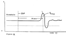
- the pattern recognition technique uses the entire pattern of the reflected pulse 82 shown in Fig. 6 and a number of sampled points taken after a reflected pulse 82 has reached a threshold voltage. The timing of the points must fall within specific boundaries for the pattern to be considered valid. This technique is an improvement over existing peak detection methods in that it protects against false readings due to signal-pulse spikes produced by noise and other phenomena.
- a reflected signal 200 includes a positive-going component 202 and a negative-going component 204 (shown in broken lines) and is nearly sinusoidal in shape.
- the baseline reflected signal 200 is centered about zero volts as can be seen in Fig. 6.
- the center of positive-going component 202 of the reflected signal 200 (i.e., the process material level) is determined by identifying two points 206 and 208 on the positive-going component 202 of the reflected signal 200 with respect to a threshold voltage 210. The midpoint between these points 206 and 208 is the center of the positive going component 202 of the reflected signal 200. Points on the negative going component 204 are replaced with zeroes.
- the points on the negative going component 206 are not replaced with zeroes. Instead the negative points are converted to their absolute value using the 2's complement technique.
- the 2's complement technique is well known to those skilled in the art for determining absolute value of negative signed numbers and is described and explained in standard textbooks. See for example the textbook Digital Concepts & Applications , published 1990 by Saunder s College Publishing (a division of Holt, Rinehart and Winston) p. 225.
- the result of the use of the 2's complement technique is a second positive-going component 212 creating dual positive-going peaks 202 and 212.
- the valid interface 26 for the process material is determined by using a four (4) point pattern and the dual positive-going peaks 202 and 212 of the entire reflected pulse 200.
- the first point 206 is detected relative to the threshold voltage 210 the second point 208, third point 214 and the fourth point 216 on the positive going peaks 202 and 212 must occur within specific time frames from the first point 206.
- the time frames are determined by the overall 218 width of the valid reflected pulse 200. If the four (4) points 206, 208, 214 and 216 do not occur within the specific time frames then the reflected pulse 200 is considered invalid.
- the center of the first positive-going peak 202 i.e. the valid interface 26 for the process material
- the center of the first positive-going peak 202 is determined by calculating the mid-point between the first point 206 and the second point 208. It will be understood that the number of points in the pattern need not be limited to four. Additional points could be used without departing from the scope of the present invention.
- a further embodiment of the present invention includes a corrective element or factor that is calculated every time the software executes a signal processing loop. The correction element or factor is then added to each signal sample prior to use of the baseline subtraction method described previously.
- an initial boundary or probe map time aligned signal 220 that has been digitized and store in a microprocessor is shown.
- This signal 220 corresponds to signal 62 shown in Fig. 3.
- the signal 220 is time aligned relative a starting voltage V min which is located on the starting center line 222 of the negative going component 224 of the signal 220.
- Figure 11 illustrates a situation where the real time TDR signal 226 has drifted in both time and voltage relative to the initial boundary signal 220.
- the real time TDR signal 226 has a new center line 228 which has shifted in time ⁇ t i and has shifted in voltage ⁇ v compi .
- the compensation can be accomplished by obtaining the time and voltage variations ⁇ t i and ⁇ v compi and adjusting the digitized real time TDR signal 226 by the drift ⁇ t i and ⁇ v compi .
- the correction factor V corr is calculated by subtracting a specific point 230 on the negative-going component 224 of the initial boundary of the probe map signal 220 from its corresponding point 232 on the negative-going component 234 of the real-time TDR signal 226, then inverting the result using the 2's complement technique. This yields a number V corr that is always added to the real time TDR signal 226, regardless of offset polarity of the signals 220 and 226.
- V comp V sample + V corr
- Figs. 13 and 14 illustrate the additional steps performed by the microprocessor 46 as a result of the software modifications.
- the additional steps are shown inserted in the appropriate locations within the steps illustrated in Fig. 8.
- reference numerals in Figs. 13 and 14 corresponding to reference numerals in Fig. 8 are intended to denote the same steps.
- Steps 136-140, steps 120-126 and steps 114-118 would not be performed when using the pattern recognition technique.
- the correction factor could be used without the pattern recognition technique in which case all of the steps in Fig. 8 may be performed.
- the step for calculating and adding the correction factor is shown in block 250 and is performed between blocks 112 and 128 in the process illustrated in Fig. 8.
- a more detailed breakdown of the steps performed in block 250 is shown in Fig. 14.
- the microprocessor 46 After the microprocessor 46 provides a time alignment of the TDR signal in block 112, the microprocessor 46 then subtracts the specific point 230 on the initial boundary signal 220 from the corresponding point 232 on the real-time signal 226 in block 252 in accordance with the formula set forth above. In block 254, the microprocessor 46 then uses the 2's complement technique on the negative difference value between points 232 and 230.
- the correction factor V corr determined in block 252 is added to the uncompensated sample point of the real time TDR signal to produce a value of the compensated sample point V comp .
- the microprocessor 46 calculates a baseline (BL) signal by subtracting the initial boundary signal from the time aligned and corrected TDR signal to produce the baseline signal illustrated in analog form in Fig. 12. It will be understood that after block 123 the microprocessor 46 may proceed to block 136, block 120, block 114 or use the pattern recognition technique as shown in Fig. 13 at 260.
- the microprocessor 46 uses the 2's complement technique on the negative-going component 204 of the baseline signal 200 (See Fig. 9) in block 262. Thereafter the microprocessor 46 searches for the predetermine four (4) point pattern (determined based upon the width 218 of the signal) in block 264 as shown in Fig. 9. If the predetermined pattern is not found then the microprocessor 46 continues to search baseline signal samples until a valid pattern is found. This step is performed in block 266. Once a valid patter is found, then the microprocessor 46 determines a location of the positive maximum value of the valid baseline signal in block 130 shown in Fig. 8.
Abstract
Description
- The present invention relates to a processor apparatus and method for a process measurement signal. More particularly, the present invention relates to an improved processor for time-of-flight signals to provide an accurate indication of the location of an interface between a first medium and a second medium in a vessel.
- The process and storage industries have long used various types of equipment to measure process parameters such as level, flow, temperature, etc. A number of different techniques (such as mechanical, capacitance, ultrasonic, hydrostatic, etc.) provide measurement solutions for many applications. However, many other applications remain for which no available technology can provide a solution, or which cannot provide such a solution at a reasonable cost. For many applications that could benefit from a level measurement system, currently available level measurement systems are too expensive.
- In certain applications, such as high volume petroleum storage, the value of the measured materials is high enough to justify high cost level measurement systems which are required for the extreme accuracy needed. Such expensive measurement systems can include a servo tank gauging system or a frequency modulated continuous wave radar system.
- Further, there are many applications that exist where the need to measure level of the product is high in order to maintain product quality, conserve resources, improve safety, etc. However, lower cost measurement systems are needed in order to allow a plant to instrument its measurements fully.
- There are certain process measurement applications that demand other than conventional measurement approaches. For example, applications demanding high temperature and high pressure capabilities during level measurements must typically rely on capacitance measurement. However, conventional capacitance measurement systems are vulnerable to errors induced by changing material characteristics. Further, the inherent nature of capacitance measurement techniques prevents the use of such capacitance level measurement techniques in vessels containing more than one fluid layer.
- Ultrasonic time-of-flight technology has reduced concerns regarding level indications changing as material characteristics change. However, ultrasonic level measurement sensors cannot work under high temperatures, high pressures, or in vacuums. In addition, such ultrasonic sensors have a low tolerance for acoustic noise.
- One technological approach to solving these problems is the use of guided wave pulses. These pulses are transmitted down a dual probe transmission line into the stored material, and are reflected from probe impedance changes which correlate with the fluid level. Process electronics then convert the time-of-flight signals into a meaningful fluid level reading. Conventional guided wave pulse techniques are very expensive due to the nature of equipment needed to produce high-quality, short pulses and to measure the time-of-flight for such short time events. Further, such probes are not a simple construction and are expensive to produce compared to simple capacitance level probes.
- Recent developments by the National Laboratory System now make it possible to generate fast, low power pulses, and to time their return with very inexpensive circuits. See, for example, U.S. Patent Nos. 5,345,471 and 5,361,070. However, this new technology alone will not permit proliferation of level measurement technology into process and storage measurement applications. The pulses generated by this new technology are broadband, and also are not square wave pulses. In addition, the generated pulses have a very low power level. Such pulses are at a frequency of 100 MHz or higher, and have an average power level of about 1nW or lower. These factors present new problems that must be overcome to transmit the pulses down a probe and back and to process and interpret the returned pulses.
- First, a sensor apparatus must be provided for transmitting these low power, high frequency pulses down a probe and effecting their return. Such appropriate sensor apparatus is described in a copending U.S. Patent Application Serial No. 08,574,818, entitled SENSOR APPARATUS FOR PROCESS MEASUREMENT, filed December 19, 1995 and a copending U.S. Patent Application Serial No. 08/735,736 entitled SENSOR APPARATUS FOR PROCESS MEASUREMENT, filed October 23, 1996, the disclosures of which are hereby expressly incorporated by reference into the present application.
- The sensor apparatus is particularly adapted for the measurement of material levels in process vessels and storage vessels, but is not limited thereto. It is understood that the sensor apparatus may be used for measurement of other process variables such as flow, composition, dielectric constant, moisture content, etc. In the specification and claims, the term "vessel" refers to pipes, chutes, bins, tanks, reservoirs or any other storage vessels. Such storage vessels may also include fuel tanks, and a host of automotive or vehicular fluid storage systems or reservoirs for engine oil, hydraulic fluids, brake fluids, wiper fluids, coolant, power steering fluid, transmission fluid, and fuel.
- The present invention propagates electromagnetic energy down an inexpensive, signal conductor transmission line as an alternative to conventional coax cable or dual transmission lines. The Goubau line lends itself to applications for a level measurement sensor where an economical rod or cable probe (i.e., a one conductor instead of a twin or dual conductor approach) is desired. The single conductor approach enables not only taking advantage of new pulse generation and detection technologies, but also constructing probes in a manner similar to economical capacitance level probes.
- The present invention specifically relates to a signal processor apparatus for processing and interpreting the returned pulses from the conductor. Due to the low power, broadband pulses used in accordance with the present invention, such signal processing to provide a meaningful indication of the process variable is difficult. Conventional signal processing techniques use only simple peak detection to monitor reflections of the pulses.
- The present invention provides signal processing circuitry configured for measurement of the time-of-flight of very fast, guided wave pulses. Techniques used in similar processes, such as ultrasonic level measurement are vastly different from and are insufficient for detection of guided electromagnetic wave pulses due to the differences in signal characteristics. For example, ultrasonic signals are much noisier and have large dynamic ranges of about 120 dB and higher. Guided electromagnetic waves in this context are low in noise and have low dynamic ranges (less than 10:1) compared to the ultrasonic signals, and are modified by environmental impedances. The signal processor of the present invention is configured to determine an appropriate reflection pulse of these low power signals from surrounding environmental influences.
- Standard electromagnetic reflection measurements are known as time domain reflectometry (TDR). TDR devices for level measurement require the measuring of the time of flight of a transit pulse and a subsequently produced reflective pulse received at the launching site of the transit pulse. This measurement is typically accomplished by determining the time interval between the maximum amplitude of the received pulse. The determination of this time interval is done by counting the interval between the transmitted pulse and the received pulse.
- The present invention provides an improved signal processor for determining a valid reflective pulse signal caused by an interface of material in contact with a probe element of a sensor apparatus. The processor apparatus of the present invention is particularly useful for processing high speed, low power pulses as discussed above. In the preferred embodiment of the signal processor apparatus, processing is performed based on a digital sampling of an analog output of the reflective pulses. It is understood, however, that similar signal processing techniques can be used on the analog signal in real time.
- It is well known that variations in operating conditions such as environmental variations like temperature, humidity, and pressure; power variations like voltage, current, and power; electromagnetic influences like radio frequency/microwave radiated power which creates biases on integrated circuit outputs; and other conditions such as mechanical vibration can induce undesired drifts of electronics parameters and output signals. The present invention provides a processing means and method for compensating for signal drifts caused by these operating conditions.
- According to one aspect of the present invention, a method is provided for processing a time domain reflectometry (TDR) signal to generate an output result corresponding to a valid process variable. The method includes the steps of processing the TDR signal using at least two different techniques for detecting a valid reflection pulse generated by the process variable to calculate an independent result using each of the at least two techniques, and applying a weighted factor to the independent results from each of the at least two different techniques to provide weighted output results. The method also includes the steps of comparing the weighted output results, and selecting the valid output result from the weighted output results based on the comparing step. In the illustrated method, the comparing step includes the step of summing the weighted factors for each independent result.
- According to another aspect of the present invention, a method is provided for processing a time domain reflectometry (TDR) signal having a plurality of reflection pulses to generate a valid output result corresponding to a reflection pulse caused by a process variable. The method includes the steps of processing the TDR signal using a first method for detecting the reflection pulse generated by the process variable and for calculating a first output result, processing the TDR signal using a second method for detecting the reflection pulse generated by the process variable and for calculating a second output result, and processing the TDR signal using a third method for detecting the reflection pulse generated by the process variable and for calculating a third output result. The method also includes the steps of comparing the first, second, and third results, and selecting the valid output result based on the comparing step.
- In the illustrated method, the comparing step includes the step of applying a weighted factor to each of the first, second, and third results prior to the selecting step. The comparing step also includes the step of summing the weighted factors for each of the first, second, and third results.
- Also in the illustrated embodiment, the first processing method includes the steps of detecting a maximum value reflection pulse from the plurality of reflection pulses of the TDR signal and calculating the first result based on the maximum value reflection pulse of the TDR signal. The second processing method includes the steps of calculating a derivative of the TDR signal, determining a location of a zero crossing adjacent an absolute maximum value of the derivative TDR signal, and calculating the second result based on said zero crossing. The third processing method includes the steps of establishing an initial boundary reflection signal, determining a baseline signal by subtracting the initial boundary signal from the TDR signal, determining a maximum value reflection pulse of the baseline signal, and calculating the third result based on the maximum value reflection pulse of the baseline signal.
- The method further includes the step of processing the TDR signal using a fourth method for detecting the reflection pulse generated by the Process variable and for calculating a fourth output result. The comparing step compares the first, second, third, and fourth results. Illustratively, the comparing step includes the step of applying a weighted factor to each of the first, second, third, and fourth results prior to the selecting step. The fourth processing method illustratively includes the steps of calculating a derivative of the baseline signal, determining a time position of a zero crossing adjacent an absolute maximum of the derivative of the baseline signal, and calculating the fourth result based on the zero crossing adjacent the absolute maximum of the derivative of the baseline signal.
- According to yet another aspect of the present invention, a method is for processing a time domain reflectometry (TDR) signal having a plurality of reflection pulses to generate a valid output result corresponding to a reflection pulse caused by a process variable in a vessel. The TDR signal is generated by a sensor apparatus. The method includes the steps of establishing an initial boundary signal for the sensor apparatus before the process variable is located in the vessel, and storing the detected initial boundary signal. The method also includes the steps of detecting the TDR signal, detecting a maximum value reflection pulse from the plurality of reflection pulses of the TDR signal, and calculating a first output result based on the maximum value reflection pulse of the TDR signal. The method further includes the steps of calculating a derivative of the TDR signal, determining a location of a zero crossing adjacent an absolute maximum value of the derivative TDR signal, calculating a second output result based on the zero crossing adjacent an absolute maximum value of the derivative TDR signal. The method still further includes the steps of determining a baseline signal by subtracting the initial boundary signal from the TDR signal, determining a maximum value of the baseline signal, and calculating a third output result based on the maximum value of the baseline signal. The method includes the steps of calculating a derivative of the baseline signal, determining a time position of a zero crossing adjacent an absolute maximum of the derivative of the baseline signal, and calculating a fourth output result based on the zero crossing adjacent the absolute maximum of the derivative of the baseline signal. The method also includes the steps of comparing the first, second, third, and fourth output results, and selecting the valid output result from the weighted output results based on the comparing step.
- In the illustrated method, the comparing step includes the step of applying weighted factors to the first, second, third, and fourth results to produce weighted results. The comparing step also includes the step of selecting the valid output result from the weighted results.
- The illustrated method also includes the step of establishing a new initial boundary reflection signal at a selected time, and storing the new initial boundary signal to update the baseline signal. The comparing step may include the steps of comparing the first, second, and third results to a previous output result, and disregarding a particular result which deviates from the previous output result by more than a selected amount.
- According to a further aspect of the present invention, a method is provided for processing a time domain reflectometry (TDR) signal having a plurality of reflection pulses to generate a valid output result corresponding to a reflection pulse caused by a process variable. The method includes the steps of processing the TDR signal using a primary detection method for detecting the reflection pulse generated by the process variable and for calculating a primary output result, and processing the TDR signal using at least one secondary method for detecting the reflection pulse generated by the process variable and for calculating at least one secondary output result. The method also includes the steps of comparing the primary result to the at least one secondary result to check the primary result, and selecting the valid output result based on the comparing step. In the illustrated method, the comparing step includes the step of applying a weighted factor to the primary result and each of the secondary results prior to the selecting step.
- According to a still further aspect of the present invention, an apparatus is provided for processing a time domain reflectometry (TDR) signal having a plurality of reflection pulses to generate a valid output result corresponding to a reflection pulse caused by a process variable. The apparatus includes means for processing the TDR signal using a first method for detecting the reflection pulse generated by the process variable and for calculating a first output result, for processing the TDR signal using a second method for detecting the reflection pulse generated by the process variable and for calculating a second output result, and for processing the TDR signal using a third method for detecting the refleciton pulse generated by the process variable and for calculating a third output result, means for comparing the first, second, and third results, and means for selecting the valid output result.
- In the illustrated embodiment, the apparatus further includes means for processing the TDR signal using a fourth method for detecting the reflection pulse generated by the process variable and for calculating a fourth output result. The comparing means compares the first, second, third, and fourth results. The comparing means illustratively includes means for applying a weighted factor to each of the first, second, third, and fourth results.
- According to an additional aspect of the present invention, an apparatus is provided for processing a time domain reflectometry (TDR) signal having a plurality of reflection pulses to generate a valid output result corresponding to a refleciton pulse caused by a process variable. The apparatus includes means for processing the TDR signal using a primary detection method for detecting the reflection pulse generated by the process variable and for calculating a primary output result, for processing the TDR signal using at least one secondary method for detecting the reflection pulse generated by the process variable and for calculating at least one secondary output result, for comparing the primary result to the at least one secondary result to check the primary result, and for selecting the valid output result based on the comparison. In the illustrated embodiment, the comparing means includes means for applying a weighted factor to the primary result and each of the secondary results.
- According to a further aspect of the present invention, a method is provided for processing a time domain reflectometry (TDR) signal to generate a valid output result corresponding to a process variable in a vessel. The method includes the steps of establishing an initial boundary signal before the process variable is located in the vessel; storing the initial boundary signal and detecting a TDR signal. The method also includes the steps of determining a baseline signal by subtracting the initial boundary signal from the TDR signal, establishing a signal pattern having a time range based on the width of reflection pulses in the baseline signal and comparing the baseline signal to the signal pattern until a reflection pulse in the baseline signal matches the signal pattern.
- According to another aspect of the present invention, a method for processing a time domain reflectometry (TDR) signal to generate a valid output result corresponding to a process variable in a vessel includes the steps of establishing an initial boundary signal before the process variable is located in the vessel, storing the initial boundary signal, and detecting the TDR signal. The method further includes the steps of determining a point on the initial boundary signal and a corresponding point on the TDR signal, calculating a correction factor by subtracting the point on the initial boundary signal from the corresponding point on the TDR signal, and adding the correction factor to the TDR signal to establish a valid TDR signal. The method further includes the step of determining a baseline signal by subtracting the initial boundary signal from the valid TDR signal.
- In the illustrated embodiment, the first processing method includes the steps of establishing a threshold voltage prior to comparing the baseline signal to the signal pattern and converting negative-going components of the reflection pulses to positive-going components. Further, in the first processing method the step of establishing a signal pattern includes the step of determining at least four points within the time range in proximity to the threshold voltage and the step of comparing the baseline signal to the signal pattern includes the step of searching for a reflection pulse where the four points are on the reflection pulse in proximity to the threshold voltage.
- In another illustrated embodiment, the second processing method includes the step of converting the correction factor to a positive value prior to adding the correction factor to the TDR signal to establish the valid TDR signal.
- In both illustrated methods, the processing methods include the steps of determining a maximum value of the baseline signal and calculating an output result based on the maximum value.
- According to a further aspect of the present invention, an apparatus is provided for processing a time domain reflectometry (TDR) signal having a plurality of reflection pulses to generate a valid output result corresponding to a process variable in a vessel. The apparatus includes means for establishing an initial boundary signal before the process variable is located in the vessel, means for storing the initial boundary signal, means for detecting the TDR signal, and means for determining a baseline signal by subtracting the initial boundary signal from the TDR signal. The apparatus further includes means for establishing a signal pattern having a time range based on the width of reflection pulses in the baseline signal and means for comparing the baseline signal to the signal pattern until a reflection pulse in the baseline signal matches the signal pattern.
- According to yet another aspect of the present invention an apparatus is provided for processing a time domain reflectometry (TDR) signal having a plurality of reflection pulses to generate a valid output results corresponding to a process variable in a vessel. The apparatus includes means for establishing an initial boundary signal before the process variable is located in the vessel, means for storing the initial boundary signal, and means for detecting the TDR signal. The apparatus further includes means for determining a point on the initial boundary signal and a corresponding point on the TDR signal, means for calculating a correction factor by subtracting the point on the initial boundary signal from the corresponding point on the TDR signal, means for adding the correction factor to the TDR signal to establish a valid TDR signal, and means for determining a baseline signal by subtracting the initial boundary signal from the valid TDR signal.
- The illustrated embodiments of the apparatus also include means for determining a maximum value of the baseline signal and means for calculating an output result based on the maximum value.
- Additional objects, features, and advantages of the invention will become apparent to those skilled in the art upon consideration of the following detailed description of the preferred embodiment exemplifying the best mode of carrying out the invention as presently perceived.
- The detailed description particularly refers to the accompanying figures in which:
- Fig. 1 is a diagrammatical view illustrating a single conductor material level sensor for measuring a level of a process variable such as a liquid in a vessel, and illustrating a block diagram of the pulse transmitter and receiver and the processing circuitry for determining the level of the process variable;
- Fig. 2 is an analog signal output of the time domain reflectometry (TDR) signal generated by the transmitter and a receiver;
- Fig. 3 is an analog output signal indicating an initial boundary condition of the inside of the vessel before the process variable is located in the vessel;
- Fig. 4 is a time aligned analog TDR output signal:
- Fig. 5 is an analog derivative signal of the time aligned TDR signal of Fig. 4;
- Fig. 6 is an analog baseline signal generated when the initial boundary signal of Fig. 3 is subtracted from the time aligned TDR output signal of Fig. 4;
- Fig. 7 is an analog signal of a derivative of the baseline signal of Fig. 6;
- Fig. 8 is a flow chart illustrating the steps performed by the processor apparatus of the present invention to determine an actual, valid level indication of the process variable based on a reflective pulse caused by the process variable;
- Fig. 9 is an analog baseline signal corresponding to the signal shown in Fig. 6 illustrating the pattern recognition technique of determining the valid baseline signal;
- Fig. 10 is an analog initial boundary or probe map time aligned signal corresponding to Fig. 3;
- Fig. 11 is an analog illustration of the drift of a real time initial boundary signal relative to the initial boundary signal shown in Fig. 10 caused by variations in operating conditions;
- Fig. 12 is an analog illustration of a baseline signal after the application of a correction factor according to the present inventor to compensate for the drift in the signal shown in Fig. 11;
- Fig. 13 is a segment of the flow chart illustrated in Fig. 8 incorporating the steps performed by the processor apparatus of the present inventor to determine and apply the correction factor and to use the pattern recognition technique to determine an actual, valid level indication of the process variable based on a reflective pulse caused by the process variable; and
- Fig. 14 is a flow chart expanding the steps performed in
block 250 in Fig. 13 for calculating and adding the correction factor to the initial boundary signal. - Referring now to the drawings, Fig. 1 provides a diagrammatical illustration of operation of the surface wave transmission line sensor apparatus for process measurement. The
apparatus 10 is adapted for use with level measurement of a process variable such as an interface between afirst medium 11 and a second medium 12 located within astorage vessel 14. Illustratively, thefirst medium 11 is air and thesecond medium 12 is a process variable such as a liquid or other material. - The present invention includes a mechanical mounting
apparatus 16 for securing a single conductor transmission line orprobe element 18 to asurface 20 of thevessel 14. Themechanical mounting apparatus 16 enables atransceiver 22 to transmit pulses onto theprobe element 18 in the direction ofarrow 24. Once the pulses reach aninterface 26 between thefirst medium 11 and thesecond medium 12, such as a top surface of liquid, a reflective pulse is returned back up theprobe element 18 in the direction ofarrow 28. - The
transceiver 22 is coupled to processing circuitry which detects the reflected pulses to interpret the return pulses and to generate an output signal indicating the level of second medium 12 in thevessel 14. Preferably, thetransceiver 22 transmits broadband pulses at very low average power levels such as about 1nW or less, or 1µW or less peak power. The frequency of the pulses is preferably about 100 MHz or greater. - The
transceiver 22 includes a transmitpulse generator 30 which generates a series of the high frequency pulses and transmits these pulses via acable 32 to mounting 16.Transceiver 22 also includes asequential delay generator 32 coupled to the transmitpulse generator 30. Asample pulse generator 34 is coupled to thesequential delay generator 32. A sample and holdbuffer 36 is coupled to samplepulse generator 34 and to the cable 37. Illustratively,transceiver 22 is a micropower wide band impulse radar transmitter developed by the Lawrence Livermore National Laboratory located at the University of California located in Livermore, California. It is understood, however, thatother transceivers 22 may also be used with the signal processor apparatus of the present invention. - As discussed above, the mounting
apparatus 16 must be specially designed to transmit and receive the low power, high frequency pulses. The above-referenced copending applications, the disclosures of which are expressly incorporated by reference, provide a suitable mountingapparatus 16 fortransceiver 22. It is understood that the electronics and processing circuitry may be located at a remote mounting location spaced apart from the mountingapparatus 16. - An output from
transceiver 22 online 38 is coupled to anamplifier 40. An output fromamplifier 40 provides a TDR analog signal online 42. Although the preferred embodiment of the present invention uses a digital sampling system and processes digital signals related to the analog output signals, it is understood that a processor apparatus in accordance with the present invention may be built to process the analog signal directly. - In the present invention, an analog-to-
digital converter 44 is coupled toamplifier 40. An output of the analog-to-digital converter 44 is coupled to an input ofmicroprocessor 46. In the illustrated embodiment,microprocessor 46 is a MC68HC711E9 microprocessor available from Motorola. It is understood, however, that any other suitable microprocessor may be used in accordance with present invention.Microprocessor 46 is used to implement both a fast clock and a slow clock. A PRF clock implemented bymicroprocessor 46, which is a square wave at about 2 MHz, is coupled to transmitpulse generator 30. Themicroprocessor 46 also implements a sync oscillator, which is illustratively a square wave having a frequency of about 40 Hz. The sync oscillator is coupled tosequential delay generator 32. -
Microprocessor 46 is also coupled toRAM 48 and toEEPROM 50. An output terminal ofmicroprocessor 46 is coupled to anoutput 52. Illustratively,output 52 provides a 4-20 mA output signal to provide an indication of the level of theinterface 26 between thefirst medium 11 and thesecond medium 12. - The TDR analog signal from
amplifier 40 is an equivalent time signal (ETS) of the real time signal traveling on the transmission line system. The ETS is expanded in time by way of digital sampling, thereby enabling the use of conventional hardware for signal conditioning and processing. The signal processor of the present invention provides means for determining a valid pulse reflection, whether in real time or from the ETS. These results allow flexibility to determine information relating to the position ofmediums top surface 20, abottom surface 21, a sensor launch plate, or anend 19 of theprobe element 18. The process material positional information is derived from signal reflections caused by impedance discontinuities on the transmission line and subsequent signal processing. - The signal responses of a transmission line which includes
cable 32, mounting 16, and probeelement 18 are dependent upon the inherent transmission design characteristics and impedance changes created by changing boundary conditions. These boundary conditions are used to determine changes in the sensor environment and are directly or indirectly related to the amount or position of the bulk process materials being measured. The impedance of the sensor at a given location can change with variations of the sensors environment or boundary condition due to interaction of the sensor, its signal, and its surroundings.
- An example of a time domain reflectometry (TDR) analog signal from
amplifier 40 is illustrated in Fig. 2. In Fig. 2, the first large voltage fluctuation orpulse 54 is generated by the impedance change in the mounting 16. In the preferred embodiment, the mounting 16 provides this impedance change as a reference reflective pulse. The secondreflective pulse 56 in Fig. 2 is generated by an inherent interference withinvessel 14. Thisinterference reflection 56 may be caused by a ladder, door, weld seam, material buildup, or other internal factor fromvessel 14. The thirdreflective pulse 58 is provided by theinterface 26 between thefirst medium 11 and thesecond medium 12. The fourthreflective pulse 60 is generated by anend 19 ofprobe element 18. - The present invention initializes the signal processing function by characterizing or recording sensor performance at a given time or under known boundary conditions so that this initial characterization can be used as an initial boundary condition. In other words, a reference or initial boundary signal is measured and stored before the first and
second mediums vessel 14. - An example of an initial boundary signal (I.B.) is illustrated in Fig. 3. The initial boundary signal is used to help determine a valid impedance change induced reflective pulse caused by
interface 26 between first medium 11 andsecond medium 12. In Fig. 3, the initial voltage peak orreflective pulse 62 is caused by the interference in thevessel 14.Pulse 62 of Fig. 3 corresponds topulse 56 in Fig. 2.Pulse 64 in Fig. 3 corresponds to theend 19 ofprobe element 18. - The sensor characterization may include factory calibration, environmental characterization or probe mapping, and sensor recharacterization, or recalibration. The characterization can be done in such a way to permit use of only one or a combination of initialization procedures to provide optimum performance. The characterization of the sensor and its signals inside or outside of its installation environment such as the mounting in the
vessel 14 are referred to as its initial boundary conditions. - Factory calibration may include characterizing sensor performance in a stable, known environment which provides a baseline for the system performance while neglecting the influences and effects that are encountered in field installation. A field installation, such as mounting the sensor in a tank or
vessel 14, can present an environment for new boundary conditions to the sensor caused by the vessel or permanent contents of the vessel which influence the sensor response due to interaction of the sensor with these vessel contents. - The present invention provides either an automatic recharacterization or a manual recharacterization of the sensor which can be performed to re-establish a new baseline or probe map which enables these environmental changes to be accounted for in determining the valid signal indicating the desired process variable.
- A second phase of the signal processor of the present invention involves detecting the pulse reflection produced by a valid signal response of the impedance change along a conductor. In other words, the processor apparatus locates the impedance pulse reflection caused by the
interface 26 between thefirst medium 11 and the second medium 12 in contact with theprobe element 18. A number of mathematical techniques can be used to determine the positional information due to impedance changes which generate a signal reflection related in time to the position of the cause of the impedance change along theprobe element 18. - Detection of impedance changes may include one or more of the following techniques applied to the TDR analog output signal illustrated in Fig. 2. One detection method is a peak amplitude detection of a Time Aligned TDR signal which is illustrated in Fig. 4. In other words, the signal of Fig. 4 is shifted so that time zero is set as the time of the
initial reflecting pulse 54 provided by the impedance change at the mounting 16. In Fig. 4, thefirst reflection pulse 66 is caused by the interference withinvessel 14.Second reflection pulse 68 is caused byinterface 26. Thethird reflection pulse 70 is caused byend 19 of theprobe element 18. - Another detection technique is to determine the first zero crossing after the positive peak of a first derivative signal of the Time Aligned TDR signal of Fig. 4. This derivative signal is illustrated in Fig. 5. Again, the first reflection pulse 72 is caused by the interference within
vessel 14. Thesecond reflection pulse 74 is caused byinterface 26, and thethird reflection pulse 76 is caused byend 19 ofprobe element 18. Using this technique, the processor apparatus determines the maximum absolute value of the peak reflective pulse, which is illustratively atlocation 78. If the absolute maximum was a negative value, the preceding zero crossing atlocation 80 is determined to be the location ofinterface 26. If the absolute maximum was a positive peak, the next subsequent zero crossing is used as the indication ofinterface 26. - Yet another technique for determining the
valid interface 26 is the use of a baseline signal. The baseline signal is illustrated in Fig. 6. The baseline signal is determined by subtracting the initial boundary signal of Fig. 3 from the Time Aligned TDR signal of Fig. 4. Therefore, thepulse reflection 66 caused by the interference withinvessel 14 is cancelled by the initialboundary pulse reflection 62. In Fig. 6, theinitial pulse reflection 82 is therefore caused by theinterface 26 between thefirst medium 11 and thesecond medium 12.Reflective pulse 84 is caused by theend 19 ofprobe element 18. The processor determines the time of the greatestpositive peak 86 as the pulse reflection caused byinterface 26. - Still another technique for determining the actual position of
interface 26 is to use the first derivative signal of the baseline signal of Fig. 6. The derivative of the baseline signal is illustrated in Fig. 7. Again, thefirst reflection pulse 88 is caused by theinterface 26 between first medium 11 andsecond medium 12. Thesecond reflection pulse 90 is caused byend 19 ofprobe element 18. The processor determines the peak absolute value 92 of thepulse reflection 88. Since the peak absolute value is associated with a negative voltage, the processor proceeds to the first proceeding zerocrossing 94 as the time for theinterface 26. If the maximum absolute value was a positive peak, the next subsequent zero crossing is used as the interface level. - Some embodiments of the present invention use a combination of two or more of the above-cited techniques to verify the data related to the valid detection of
interface 26. The short term history of the signal can also be used to substantiate the validity of any change in position of theinterface 26 and to verify that this change is possible within the process condition presently being used in the vicinity of the sensor. - In a preferred embodiment of the present invention, the processor determines the location of the valid impedance discontinuity caused by
interface 26 between first medium 11 and second medium 12 using each of the four techniques or methods discussed above. Each method is assigned a weighted factor. In the illustrated embodiment, the baseline signal calculation illustrated in Fig. 6 is assigned a weighted factor of 1.1, while the other three techniques are assigned a weighted factor of 1.0. These weighted factors provide means for showing the degree of agreement among the four methods. If the calculated boundary conditions as detected by the sensor creates a conflict among the four detection methods such that there is not a substantial agreement of all four methods, then a valid result is dependent upon whether there is substantial agreement between two or three of the detection methods. If there is substantial deviation in the detection of the valid impedance pulse by all four methods, then the method having the highest weighted factor is used as the valid detection. - In the present invention, the
microprocessor 46 is programmed with software to calculate the position of the valid impedance change caused byinterface 26 using each of the four methods discussed above. Fig. 8 illustrates the steps performed by themicroprocessor 46 of the present invention to determine the valid signal. Themicroprocessor 46 is first initialized as illustrated atblock 100. Operation mode of the signal processor is illustrated atblock 102. - The first operational mode is to set and store the initial boundary (I.B.) signal illustrated in Fig. 3. This initial boundary signal is generated before the process material is placed in
vessel 14.Microprocessor 46 first receives an input initial boundary signal as illustrated atblock 104. The data is then time aligned based on the initial impedance change caused by the mounting 16 as illustrated asblock 106.Microprocessor 46 then stores the time aligned data related to the initial boundary conditions in theEEPROM 50 as illustrated atblock 108. Once the initial boundary signal is stored,microprocessor 46 returns to operation mode atblock 102. - In one embodiment, the signal processor of the present invention may establish the initial boundary conditions manually only during initial installation of the
sensor apparatus 10 into thevessel 14. In another instance, the initial boundary conditions may be updated at predetermined times during operation of the signal processor. - During normal operation of the signal processor,
microprocessor 46 receives an input TDR signal as illustrated atblock 110. This input TDR signal is a digital representation from analog-to-digital converter 44 of the TDR analog signal illustrated in Fig. 2. Although reference will be made to the analog signals in Figs. 2-7, it is understood that themicroprocessor 46 of the present invention uses the digital representation of these signals. It is also understood that an analog processor may be used to process the analog signals in accordance with the present invention. -
Microprocessor 46 next provides a time alignment of the TDR signal as illustrated atblock 112. In other words,microprocessor 46 time shifts the input TDR signal so that the time zero begins at the location of the interface of mounting 16 which is indicated by the initiallarge reflection pulse 54 shown in Fig. 2. - In the illustrated embodiment,
microprocessor 46 uses four different detection methods to locate a valid pulse reflection indicative of theinterface 26 between thefirst medium 11 and thesecond medium 12. In a first method,microprocessor 46 detects a peak reflection pulse of the time aligned TDR signal (illustrated in Fig. 4) as illustrated inblock 114 of Fig. 8.Peak 71 in Fig. 4 is the valid reflection pulse corresponding to interface 26. However, the peak detection step in this example would determine thatpeak 115 is the valid peak. Peak 115 actually corresponds to interference invessel 14 to be the valid pulse. This explains why the peak detection method of the time aligned TDR signal, when used alone, may produce some inaccuracies.Microprocessor 46 then determines a time corresponding to the position of the maximum pulse value as illustrated atblock 116 in Fig. 8. The time value is then converted to a distance between thetop surface 20 ofvessel 14 and theinterface 26. This step is illustrated at block 118. This distance result calculated using the first detection method is then stored. - It is understood that once a time position of an impedance change on a sensor has been derived, there are a number of techniques that can be used to convert the detected time to a distance equivalent position of the
interface 26 of the process variable. The time intervals between the impedance changes have a mathematical relationship such that the time relation between the impedance change is proportional to the speed of light and a continuous function of the relative dielectric constants of the subject materials. If thefirst medium 11 is air, the dielectric constant is substantially equal to 1.0. The subject time of the interval can then be corrected by applying the continuous functional relation relative to the material dielectric and the environmental surroundings. - Other techniques such as using a sensor or conductor of a known length and then using the relationship changes of the pulse travel times form a subject material interface to an
end 19 of theprobe element 18 may be used. In other words, once the location of the valid impedance pulse is determined, a time or distance between the impedance interface and theend 19 ofprobe element 18 can be used to determine the level of theinterface 26. In the case of a sensor having a known length, differential time intervals from amaterial interface 26 to end 19 of theprobe element 18 changes proportionally with the thickness of thesubject material 12 divided by a continuous functional relationship of the material dielectric constant. Provided theprobe element 18 has a fixed location relative to thevessel 14, the material level or thickness of the material is an offset relative to sensor position. This posititional relationship is determined using a simple mathematical equations. - Similarly, the velocity of a pulse traveling on a sensor passing through multiple material layers can be used to determine the level of each material, provided the relative dielectric constant of each material is known. When the sensor has a fixed location relative to
vessel 14, the position of each material can be determined as a function of the time differential, with an offset to the sensor position. A sensor can also be designed having markers at known distances to create signal reflections that can be used for calibration and/or determining material dielectric values. -
Microprocessor 46 also calculates a derivative of the time aligned TDR signal as illustrated atblock 120. An analog representation of this derivative signal is illustrated in Fig. 5.Microprocessor 46 then determines the location of a first zero crossing adjacent an absolute maximum value of the signal. If the maximum is obtained from a positive value,microprocessor 46 determines the next subsequent zero crossing after the positive peak. If the absolute maximum was obtained from a negative value, themicroprocessor 46 determines the first zero crossing prior to the detected absolute maximum. This step is illustrated atblock 122.Microprocessor 46 then determines a time value corresponding to the detected zero crossing as illustrated atblock 124. This time value is then converted to a distance corresponding to the level of theinterface 26 between first medium 11 and second medium 12 as illustrated atblock 126. The distance calculated using the second detection Method is then stored. - In the third detection method, the
microprocessor 46 calculates a baseline (BL) signal by subtracting the initial boundary signal stored in EEPROM 50 (Fig. 3) from the time aligned TDR signal which is illustrated in analog form in Fig. 4 as illustrated atblock 128. This baseline signal is illustrated in analog form in Fig. 6.Microprocessor 46 then determines a location of the positive maximum value of the baseline signal as illustrated atblock 130. This positive maximum value is illustrated atlocation 86 in Fig. 6.Microprocessor 46 next determines the time value corresponding to the detected positive maximum value as illustrated atblock 132.Microprocessor 46 then converts the time value to a distance change indicating the location ofinterface 26 between thefirst medium 11 and second medium 12 as illustrated atblock 134. The distance calculated using the third detection methods is then stored. - In the fourth detection method,
Microprocessor 46 generates a first derivative of the baseline signal as illustrated atblock 136. An analog representation of the first derivative of the baseline signal is illustrated in Fig. 7.Microprocessor 46 then determines a location of a zero crossing adjacent an absolute maximum value as illustrated atblock 138. If the absolute maximum comes from a positive value, the next subsequent zero crossing is used. If the absolute maximum is from a negative value, the first preceding zero crossing is used as a location ofinterface 26.Microprocessor 46 then determines the time position of the zero crossing at block 140. In the Fig. 7 example, the first preceding zerocrossing 94 adjacent negative peak 92 is used as the time position.Microprocessor 46 then determines the time change as illustrated at block 142. This time change is then converted to a distance change as illustrated atblock 144 to provide an indication of the level of theinterface 26 between thefirst medium 11 andsecond medium 12. This distance change calculated using the fourth detection method is then stored. -
Microprocessor 46 next checks the validity of the detected distances from each of the four methods discussed above as illustrated atblock 146. Each of the distance changes is rounded to a predetermined sensitivity level, for example, one millimeter. If all four stored results from each of the four methods are the same,microprocessor 46 determines that a valid output has been determined. Therefore, microprocessor formats the output into an appropriate form and sends the result to theoutput 52 as illustrated atblock 150. - If the four stored results from the four detection methods are different,
microprocessor 46 then takes into account weighted factors established for each of the detection methods as illustrated atblock 152. At this point,microprocessor 46 may compare the four stored method results to a previous result. If any of the four stored results deviates from the previous result by more than a predetermined amount, themicroprocessor 46 may disregard such a stored result.Microprocessor 46 provides a summation of the weighted results as illustrated atblock 154. Examples of this summation bymicroprocessor 46 are provided below.Microprocessor 46 then selects the most appropriate distance as the valid impedance reflection frominterface 26 using the weighted results atblock 156.Microprocessor 46 then outputs this selected result atblock 150. - Three different examples are provided to illustrated the effect of the weighted factors on the process measurement.
-
Method X (cm) W.F. Selected Result Peak TDR 29.0 1.0 Der. TDR 36.9 1.0 Max. BL 37.1 1.1 37.1 Der. BL 37.3 1.0 -
Method X (cm) W.F. Selected Result Peak TDR 36.9 1.0 Der. TDR 37.3 1.0 37.3 Max. BL 37.1 1.1 Der. BL 37.3 1.0 -
Method X (cm) W.F. Selected Result Peak TDR 37.1 1.0 Der. TDR 37.3 1.0 Max. BL 37.1 1.1 37.1 Der. BL 37.3 1.0 - In Example 1, each of the detected results for the level or distance X of the
interface 26 is different. In this instance, the greatest weighted factor indicates that the maximum detected baseline value is used. Therefore, the selected result bymicroprocessor 46 is 37.1 cm. - In Example 2, the maximum baseline method still indicates a distance of 37.1 cm. However, both the derivative of the TDR signal method and the derivative of the baseline signal method provided a result of 37.3 cm. Therefore, the distance of 37.3 cm has a weighted factor of 2.0 when the two identical results are added together. Distance 36.9 cm from the peak TDR signal method has a weighted factor of 1.0. Distance 37.1 due to the maximum baseline method has a weighted factor of 1.1. Therefore,
microprocessor 46 selects the greatest weighted factor of 2.0 and the corresponding distance result of 37.3 cm during the selection step atblock 156 in Fig. 8. - In Example 3, both the peak TDR method and the maximum baseline method provided a distance result of 37.1 cm. The derivative TDR method and the derivative baseline method both produced a result of 37.3 cm. Therefore, the distance 37.1 has a weighted factor of 2.1, while the distance 37.3 cm has a weighted factor of 2.0. Therefore,
microprocessor 46 selects the result of 37.1 cm during the selection step atblock 156. - It is understood that other detection techniques may be used in accordance with the present invention. In addition, one of the other detection techniques may be applied the highest weighted factor, if desired. In an alternate embodiment, each of the detection techniques may be assigned a different weighted factor. Such weighted factors are selected and applied on the basis of application knowledge and experience.
- A further technique for determining the
valid interface 26 is pattern recognition using the baseline signal illustrated in Fig. 6. The pattern recognition technique uses the entire pattern of the reflectedpulse 82 shown in Fig. 6 and a number of sampled points taken after a reflectedpulse 82 has reached a threshold voltage. The timing of the points must fall within specific boundaries for the pattern to be considered valid. This technique is an improvement over existing peak detection methods in that it protects against false readings due to signal-pulse spikes produced by noise and other phenomena. - Referring to Fig. 9 a reflected
signal 200 includes a positive-goingcomponent 202 and a negative-going component 204 (shown in broken lines) and is nearly sinusoidal in shape. The baseline reflectedsignal 200 is centered about zero volts as can be seen in Fig. 6. - In the baseline method for determining the
valid interface 26, the center of positive-goingcomponent 202 of the reflected signal 200 (i.e., the process material level) is determined by identifying twopoints 206 and 208 on the positive-goingcomponent 202 of the reflectedsignal 200 with respect to a threshold voltage 210. The midpoint between thesepoints 206 and 208 is the center of the positive goingcomponent 202 of the reflectedsignal 200. Points on the negative goingcomponent 204 are replaced with zeroes. - In the pattern recognition technique the points on the negative going
component 206 are not replaced with zeroes. Instead the negative points are converted to their absolute value using the 2's complement technique. The 2's complement technique is well known to those skilled in the art for determining absolute value of negative signed numbers and is described and explained in standard textbooks. See for example the textbook Digital Concepts & Applications, published 1990 by Saunders College Publishing (a division of Holt, Rinehart and Winston) p. 225. The result of the use of the 2's complement technique is a second positive-goingcomponent 212 creating dual positive-goingpeaks - According to the pattern recognition technique the
valid interface 26 for the process material is determined by using a four (4) point pattern and the dual positive-goingpeaks pulse 200. Once thefirst point 206 is detected relative to the threshold voltage 210 the second point 208,third point 214 and thefourth point 216 on the positive goingpeaks first point 206. The time frames are determined by the overall 218 width of the valid reflectedpulse 200. If the four (4) points 206, 208, 214 and 216 do not occur within the specific time frames then the reflectedpulse 200 is considered invalid. - If the reflected
pulse 200 is found to be valid, then the center of the first positive-going peak 202 (i.e. thevalid interface 26 for the process material) is determined by calculating the mid-point between thefirst point 206 and the second point 208. It will be understood that the number of points in the pattern need not be limited to four. Additional points could be used without departing from the scope of the present invention. - It is well known that variations in operating conditions such as; environmental variations, (temperature, humidity, pressure,) power supply variations (voltage, current, power) electromagnetic influences (rf/uwave radiated power creating biases on IC outputs) and other conditions such as mechanical vibration can induce undesired drifts of electronics parameters and output signals.
- In order to compensate for drifts in time and voltage in reflected signals due to the above-described variations in operating conditions, a further embodiment of the present invention includes a corrective element or factor that is calculated every time the software executes a signal processing loop. The correction element or factor is then added to each signal sample prior to use of the baseline subtraction method described previously.
- Referring to Fig. 10, an initial boundary or probe map time aligned
signal 220 that has been digitized and store in a microprocessor is shown. Thissignal 220 corresponds to signal 62 shown in Fig. 3. Thesignal 220 is time aligned relative a starting voltage Vmin which is located on thestarting center line 222 of the negative goingcomponent 224 of thesignal 220. - Figure 11 illustrates a situation where the real
time TDR signal 226 has drifted in both time and voltage relative to theinitial boundary signal 220. When the baseline procedure is used in this situation, the results will not be valid. This invalid result can be overcome and corrected to compensate for these signal drifts using the correction element or factor according the present invention. The realtime TDR signal 226 has anew center line 228 which has shifted in time Δti and has shifted in voltage Δvcompi. - The compensation can be accomplished by obtaining the time and voltage variations Δti and Δvcompi and adjusting the digitized real
time TDR signal 226 by the drift Δti and Δvcompi. The correction factor Vcorr is calculated by subtracting aspecific point 230 on the negative-goingcomponent 224 of the initial boundary of the probe map signal 220 from itscorresponding point 232 on the negative-goingcomponent 234 of the real-time TDR signal 226, then inverting the result using the 2's complement technique. This yields a number Vcorr that is always added to the realtime TDR signal 226, regardless of offset polarity of thesignals 
- Vcorr =
- correction factor
- Vreal =
-
point 232 on the real-time TDR signal 226 - Vpm =
-
corresponding point 230 on the initial boundary on theprobe map signal 220 - The compensated sample point Vcomp (i.e. the center of the valid signal) is determined by the formula:

- Vcomp =
- value of the compensated sample point
- Vsample =
- value of the uncompensated point
- Vcorr =
- correction factor
- In order to implement the pattern recognition technique and the correction factor shown illustrated in Figs. 9-12, the software programmed in the
microprocessor 46 is modified as shown in Figs. 13 and 14. Figs. 13 and 14 illustrate the additional steps performed by themicroprocessor 46 as a result of the software modifications. The additional steps are shown inserted in the appropriate locations within the steps illustrated in Fig. 8. Thus reference numerals in Figs. 13 and 14 corresponding to reference numerals in Fig. 8 are intended to denote the same steps. Further, although not shown in Figs. 13 and 14, it will be understood that the remainder of the steps shown in Fig. 8 occurring before and aftersteps - Referring to Figs. 13 and 14, the step for calculating and adding the correction factor is shown in
block 250 and is performed betweenblocks block 250 is shown in Fig. 14. - Referring to Fig. 14, after the
microprocessor 46 provides a time alignment of the TDR signal inblock 112, themicroprocessor 46 then subtracts thespecific point 230 on theinitial boundary signal 220 from thecorresponding point 232 on the real-time signal 226 inblock 252 in accordance with the formula set forth above. In block 254, themicroprocessor 46 then uses the 2's complement technique on the negative difference value betweenpoints - After the 2's complement technique is applied then the correction factor Vcorr determined in
block 252 is added to the uncompensated sample point of the real time TDR signal to produce a value of the compensated sample point Vcomp. Thereafter, themicroprocessor 46 calculates a baseline (BL) signal by subtracting the initial boundary signal from the time aligned and corrected TDR signal to produce the baseline signal illustrated in analog form in Fig. 12. It will be understood that after block 123 themicroprocessor 46 may proceed to block 136, block 120, block 114 or use the pattern recognition technique as shown in Fig. 13 at 260. - Using the pattern recognition technique the
microprocessor 46 first uses the 2's complement technique on the negative-goingcomponent 204 of the baseline signal 200 (See Fig. 9) inblock 262. Thereafter themicroprocessor 46 searches for the predetermine four (4) point pattern (determined based upon thewidth 218 of the signal) inblock 264 as shown in Fig. 9. If the predetermined pattern is not found then themicroprocessor 46 continues to search baseline signal samples until a valid pattern is found. This step is performed inblock 266. Once a valid patter is found, then themicroprocessor 46 determines a location of the positive maximum value of the valid baseline signal inblock 130 shown in Fig. 8. - Although the invention has been described in detail with reference to a certain preferred embodiment, variations and modifications exist within the scope and spirit of the present invention as described and defined in the following claims.
Claims (38)
- A method for processing a time domain reflectometry (TDR) signal to generate an output result corresponding to a valid process variable, the method comprising the steps of:processing the TDR signal using at least two different techniques for detecting a valid reflection pulse generated by the process variable to calculate an independent result using each of the at least two techniques;applying a weighted factor to the independent results from each of the at least two different techniques to provide weighted output results;comparing the weighted output results; andselecting the valid output result from the weighted output results based on the comparing step.
- The method of claim 1, wherein the comparing step includes the step of summing the weighted factors for each independent result.
- A method for processing a time domain reflectometry (TDR) signal having a plurality of reflection pulses to generate a valid output result corresponding to a reflection pulse caused by a process variable, the method comprising the steps of:processing the TDR signal using a first method for detecting the reflection pulse generated by the process variable and for calculating a first output result;processing the TDR signal using a second method for detecting the reflection pulse generated by the process variable and for calculating a second output result;processing the TDR signal using a third method for detecting the reflection pulse generated by the process variable and for calculating a third output result;comparing the first, second, and third results; andselecting the valid output result based on the comparing step.
- The method of claim 3, wherein the comparing step includes the step of applying a weighted factor to each of the first, second, and third results prior to the selecting step.
- The method of claim 4, wherein the comparing step also includes the step of summing the weighted factors for each of the first, second, and third results.
- The method of claim 3, wherein the first processing method includes the steps of detecting a maximum value reflection pulse from the plurality of reflection pulses of the TDR signal and calculating the first result based on the maximum value reflection pulse of the TDR signal.
- The method of claim 6, wherein the second processing method includes the steps of calculating a derivative of the TDR signal, determining a location of a zero crossing adjacent an absolute maximum value of the derivative TDR signal, and calculating the second result based on said zero crossing.
- The method of claim 7, wherein the third processing method includes the steps of establishing an initial boundary reflection signal, determining a baseline signal by subtracting the initial boundary signal from the TDR signal, determining a maximum value reflection pulse of the baseline signal, and calculating the third result based on the maximum value reflection pulse of the baseline signal.
- The method of claim 8, further comprising the step of calculating a derivative of the baseline signal, determining a time position of a zero crossing adjacent an absolute maximum of the derivative of the baseline signal, and calculating a fourth result based on the zero crossing adjacent the absolute maximum of the derivative of the baseline signal, and wherein the comparing step compares the first, second, third, and fourth results.
- The method of claim 8, further comprising the step of reestablishing the initial boundary reflection signal at a selected time to update the baseline signal.
- The method of claim 3, further comprising the step of processing the TDR signal using a fourth method for detecting the reflection pulse generated by the process variable and for calculating a fourth output result, and wherein the comparing step compares the first, second, third, and fourth results.
- The method of claim 11, wherein the comparing step includes the step of applying a weighted factor to each of the first, second, third, and fourth results prior to the selecting step.
- The method claim 3, wherein the comparing step includes the steps of comparing the first, second, and third results to a previous output result, and disregarding a particular result which deviates from the previous output result by more than a selected amount.
- A method for processing a time domain reflectometry (TDR) signal having a plurality of reflection pulses to generate a valid output result corresponding to a refleciton pulse caused by a process variable in a vessel, the TDR being generated by a sensor apparatus, the method comprising the steps of:establishing an initial boundary signal for the sensor apparatus before the process variable is located in the vessel;storing the detected initial boundary signal;detecting the TDR signal;detecting a maximum value reflection pulse from the plurality of refleciton pulses of the TDR signal;calculating a first output res ult based on the maximum value reflection pulse of the TDR signal;calculating a derivative of the TDR signal;determining a location of a zero crossing adjacent an absolute maximum value of the derivative TDR signal;calculating a second output result based on the zero crossing adjacent an absolute maximum value of the derivative TDR signal;determining a baseline signal by subtracting the initial boundary signal from the TDR signal;determining a maximum value of the baseline signal;calculating a third output result based on the maximum value of the baseline signal;calculating a derivative of the baseline signal;determining a time position of a zero crossing adjacent an absolute maximum of the derivative of the baseline signal;calculating a fourth output result based on the zero crossing adjacent the absolute maximum of the derivative of the baseline signalcomparing the first, second, third, and fourth output results; andselecting the valid output result from the weighted output results based on the comparing step.
- The method of claim 14, wherein the comparing step includes the step of applying weighted factors to the first, second, third, and fourth results to produce weighted results, and selecting the valid output result from the weighted results.
- The method of claim 14, further comprising the step of establishing a new initial boundary reflection signal at a selected time, and storing the new initial boundary signal to update the baseline signal.
- A method for processing a time domain reflectometry (TDR) signal having a plurality of reflection pulses to generate a valid output result corresponding to a reflection pulse caused by a process variable, the method comprising the steps of:processing the TDR signal using a primary detection method for detecting the reflection pulse generated by the process variable and for calculating a primary output result;processing the TDR signal using at least one secondary method for detecting the reflection pulse generated by the process variable and for calculating at least one secondary output result;comparing the primary result to the at least one secondary result to check the primary result; andselecting the valid output result based on the comparing step.
- The method of claim 17, wherein the comparing step includes the step of applying a weighted factor to the primary result and each of the secondary results prior to the selecting step.
- An apparatus for processing a time domain reflectometry (TDR) signal having a plurality of reflection pulses to generate a valid output result corresponding to a reflection pulse caused by a process variable, the apparatus comprising means for processing the TDR signal using a first method for detecting the reflection pulse generated by the process variable and for calculating a first output result, for processing the TDR signal using a second method for detecting the reflection pulse generated by the process variable and for calculating a second output result, and for processing the TDR signal using a third method for detecting the refleciton pulse generated by the process variable and for calculating a third output result, means for comparing the first, second, and third results, and means for selecting the valid output result.
- The apparatus of claim 19, wherein the comparing means includes means for applying a weighted factor to each of the first, second, and third results.
- The apparatus of claim 19, further comprising means for processing the TDR signal using a fourth method for detecting the reflection pulse generated by the process variable and for calculating a fourth output result, and wherein the comparing means compares the first, second, third, and fourth results.
- The method claim 21, wherein the comparing means includes means for applying a weighted factor to each of the first, second, third, and fourth results.
- An apparatus for processing a time domain reflectometry (TDR) signal having a plurality of reflection pulses to generate a valid output result corresponding to a reflection pulse caused by a process variable, the apparatus comprising means for processing the TDR signal using a primary detection method for detecting the reflection pulse generated by the process variable and for calculating a primary output result, for processing the TDR signal using at least one secondary method for detecting the reflection pulse generated by the process variable and for calculating at least one secondary output result, for comparing the primary result to the at least one secondary result to check the primary result, and for selecting the valid output result based on the comparison.
- The apparatus of claim 23, wherein the comparing means includes means for applying a weighted factor to the primary result and each of the secondary results.
- A method for processing a time domain reflectometry (TDR) signal having a plurality of reflection pulses to generate a valid output result corresponding to a process variable in a vessel, the method comprising the steps of:establishing an initial boundary signal before the process variable is located in the vessel;storing the initial boundary signal;detecting the TDR signal;determining a baseline signal by subtracting the initial boundary signal from the TDR signal;establishing a signal pattern having a time range based on the width of reflection pulses in the baseline signal;comparing the baseline signal to the signal pattern until a reflection pulse in the baseline signal matches the signal pattern;determining a maximum value of the reflection pulse that matches the signal pattern; andcalculating an output result based on the maximum value.
- The method of claim 25 further comprising the steps of determining a point on the initial boundary signal and a corresponding point on the TDR signal and calculating a correction factor by subtracting the point on the initial boundary signal from the corresponding point on the TDR signal.
- The method of claim 26 further comprising the step of adding the correction factor to the TDR signal to establish a valid TDR signal prior to determining the baseline signal.
- The method of claim 25 further comprising the step of establishing a threshold voltage prior to comparing the baseline signal to the signal pattern.
- The method of claim 28 further comprising the step of inverting negative-going components of the reflection pulses to positive-going components.
- The method claim 29 wherein the step of establishing a signal pattern includes the step of determining at least four points within the time range in proximity to the threshold voltage.
- The method of claim 30 wherein the step of comparing the baseline signal to the signal pattern includes the step of searching for a reflection pulse where the four points in proximity to the threshold voltage occur within the time range.
- The method of claim 27 further comprising the step of inverting the correction factor to a positive value prior to adding the correction factor to the TDR signal to establish the valid TDR signal.
- A method for processing or time domain reflectometry (TDR) signal having a plurality of reflection pulses to generate a valid output result corresponding to a process variable in a vessel, the method comprising the steps of:establishing an initial boundary signal before the process variable is located in the vessel;storing the initial boundary signal;detecting the TDR signal;determining a point on the initial boundary signal and a corresponding point on the TDR signal;calculating a correction factor by subtracting the point on the initial boundary signal from the corresponding point on the TDR signal;adding the correction factor to the TDR signal to establish a valid signal;determining a baseline signal by subtracting the initial boundary signal from the valid TDR signal;determining a maximum value of the baseline signal; andcalculating an output result based on the maximum value.
- The method of claim 33 further comprising the step of inverting the correction factor to a positive value prior to adding the correction factor to the TDR signal to establish the valid TDR signal.
- The method of claim 33 further comprising the steps of establishing a signal pattern having a time range based on the width of the reflection pulses in the baseline signal and comparing the baseline signal to the signal pattern until a reflection pulse in the baseline signal matches the signal pattern.
- A method for processing a time domain reflectometry (TDR) signal having a plurality of reflection pulses to generate a valid output result corresponding to a process variable in a vessel, the method comprising the steps of:establishing an initial boundary signal before the process variable is located in the vessel;storing the initial boundary signal;detecting the TDR signal;determining a point on the initial boundary signal and a corresponding point on the TDR signal;calculating a correction factor by subtracting the point on the initial boundary signal from the corresponding point on the TDR signal;adding the correction factor to the TDR signal to establish a valid TDR signal;determining a baseline signal by subtracting the initial boundary signal from the valid TDR signal;establishing a signal pattern having a time range based on the width of the reflection pulses in the baseline signal;comparing the baseline signal to the signal pattern until a reflection pulse in the baseline signal matches the signal pattern;determining a maximum value of the reflection pulse thus matches the signal pattern; andcalculating an output result based on the maximum value.
- An apparatus for processing a time domain reflectometry (TDR) signal having a plurality of reflection pulses to generate a value output result corresponding to a process variable in a vessel, the apparatus comprising:means for establishing an initial boundary signal before the process variable is located in the vessel;means for storing the initial boundary signal;means for detecting the TDR signal;means for determining a baseline signal by subtracting the initial boundary signal from the TDR signal;means for establishing a signal pattern having a time range based on the width of reflection pulses in the baseline signal;means for comparing the baseline signal to the signal pattern until a reflection pulse in the baseline signal matches the signal pattern;means for determining a minimum value of the reflection pulse that matches the signal pattern; andmeans for calculating an output result based on the maximum value.
- An apparatus for processing a time domain reflectometry (TDR) signal having a plurality of reflection pulses to generate a valid output result corresponding to a process variable in a vessel, the apparatus comprising:means for establishing an initial boundary signal before the process variable is located in the vessel;means for storing the initial boundary signal;means for detecting the TDR signal;means for determining a point on the initial boundary signal and a corresponding point on the TDR signal;means for calculating a correction factor by subtracting the point on the initial boundary signal from the corresponding point on the TDR signal;means for adding the correction factor to the TDR signal to establish a valid signal;means for determining a baseline signal by subtracting the initial boundary signal from the valid TDR signal;means for determining a maximum value of the baseline signal; andmeans for calculating an output result based on the maximum value.
Applications Claiming Priority (4)
| Application Number | Priority Date | Filing Date | Title |
|---|---|---|---|
| US08/576,554 US5841666A (en) | 1995-12-21 | 1995-12-21 | Processor apparatus and method for a process measurement signal |
| US763665 | 1996-12-11 | ||
| US08/763,665 US5884231A (en) | 1995-12-21 | 1996-12-11 | Processor apparatus and method for a process measurement signal |
| US576554 | 2000-05-24 |
Publications (2)
| Publication Number | Publication Date |
|---|---|
| EP0780665A2 true EP0780665A2 (en) | 1997-06-25 |
| EP0780665A3 EP0780665A3 (en) | 1998-11-11 |
Family
ID=27076979
Family Applications (1)
| Application Number | Title | Priority Date | Filing Date |
|---|---|---|---|
| EP96120455A Withdrawn EP0780665A3 (en) | 1995-12-21 | 1996-12-19 | Processor apparatus and method for a process measurement signal |
Country Status (4)
| Country | Link |
|---|---|
| US (1) | US5884231A (en) |
| EP (1) | EP0780665A3 (en) |
| JP (1) | JP2960693B2 (en) |
| CA (1) | CA2193560C (en) |
Cited By (14)
| Publication number | Priority date | Publication date | Assignee | Title |
|---|---|---|---|---|
| EP0928974A2 (en) * | 1998-01-09 | 1999-07-14 | Endress + Hauser Gmbh + Co. | Partial probe mapping |
| EP1020735A2 (en) * | 1999-01-13 | 2000-07-19 | Endress + Hauser GmbH + Co. | Probe mapping diagnostic methods |
| WO2001029521A1 (en) * | 1999-10-15 | 2001-04-26 | Endress + Hauser Gmbh + Co.Kg | Method for increasing the interference resistance of a time frame reflectometer and a circuit device for implementing said method |
| DE10003941A1 (en) * | 2000-01-29 | 2001-08-09 | Endress Hauser Gmbh Co | Level measuring device |
| EP1186906A2 (en) * | 2000-09-11 | 2002-03-13 | VEGA Grieshaber KG | Method and device for measuring distance |
| WO2002027349A2 (en) * | 2000-09-27 | 2002-04-04 | Endress + Hauser Gmbh + Co. Kg | Method for detecting the limit state of a material, and device therefor |
| US6504793B2 (en) | 2000-09-11 | 2003-01-07 | Vega Grieshaber Kg | Method and device for range measurement |
| DE10102571A1 (en) * | 2001-01-19 | 2003-01-09 | Endress & Hauser Gmbh & Co Kg | level meter |
| US6619117B1 (en) | 1999-09-11 | 2003-09-16 | Endress + Hauser Gmbh + Co. | Level measuring instrument |
| DE102007007024A1 (en) * | 2007-02-08 | 2008-08-21 | KROHNE Meßtechnik GmbH & Co. KG | Use of a working according to the radar level gauge |
| EP2253943A1 (en) * | 2009-05-18 | 2010-11-24 | Magnetrol International Incorporated | Process measurement instrument with target rejection |
| EP2365302A1 (en) * | 2010-02-25 | 2011-09-14 | Sick Ag | Measurement of the distance to at least one initial boundary area |
| EP2474836A1 (en) * | 2011-01-11 | 2012-07-11 | Siemens Aktiengesellschaft | A method for echo processing in a pulse-echo ranging system |
| WO2015032606A1 (en) * | 2013-09-03 | 2015-03-12 | Pepperl + Fuchs Gmbh | Method for detecting a fill level in a collecting vessel |
Families Citing this family (22)
| Publication number | Priority date | Publication date | Assignee | Title |
|---|---|---|---|---|
| AU724885B2 (en) * | 1996-07-10 | 2000-10-05 | Vigilant Networks Llc | Method and system for characterizing terminations in a local area network |
| US6237410B1 (en) * | 1996-10-07 | 2001-05-29 | Circa Enterprises Inc. | Method for controlling the speed of a pump based on measurement of the fluid depth in a well |
| EP0943103A4 (en) * | 1996-11-22 | 2000-08-23 | Berwind Corp | Material level sensing |
| US6085589A (en) * | 1996-12-23 | 2000-07-11 | Venture Measurement Company Llc | Material level sensing system calibration |
| US6198424B1 (en) * | 1999-01-21 | 2001-03-06 | Rosemount Inc. | Multiple process product interface detection for a low power radar level transmitter |
| AU5746399A (en) | 1999-09-07 | 2001-04-10 | Endress & Hauser GMBH & Co. KG. | Device for determining a physical process variable of a medium |
| US6445192B1 (en) * | 2000-04-04 | 2002-09-03 | Rosemount Inc. | Close proximity material interface detection for a microwave level transmitter |
| US6681626B2 (en) * | 2000-09-18 | 2004-01-27 | Vega Grieshaber Kg | Level metering device working on the guided microwave principle, comprising a single-wire line and specific connection piece, and connection piece for a level metering device of this type |
| JP2002108836A (en) * | 2000-09-29 | 2002-04-12 | Hitachi Ltd | Processor system |
| DE10052836A1 (en) * | 2000-10-24 | 2002-05-16 | Endress Hauser Gmbh Co | Device for determining and / or monitoring a process variable |
| US6885954B2 (en) * | 2001-03-16 | 2005-04-26 | Mindspeed Technologies, Inc. | Sequence time domain reflectometry using complementary golay codes |
| US20030068024A1 (en) * | 2001-10-05 | 2003-04-10 | Jones William W. | Communication system activation |
| US6972712B1 (en) * | 2004-06-24 | 2005-12-06 | Saab Rosemount Tank Rader Ab | Near zone detection in radar level gauge system |
| US10184820B2 (en) * | 2016-09-30 | 2019-01-22 | Rosemount Tank Radar Ab | Guided wave radar level gauge system for interface measurement |
| EP3315784B1 (en) * | 2016-10-25 | 2022-10-12 | Grundfos Holding A/S | Submersible pump unit and method of operating a submersible pump unit |
| RU2670367C1 (en) * | 2017-11-03 | 2018-10-22 | Федеральное государственное бюджетное учреждение науки Институт проблем управления им. В.А. Трапезникова Российской академии наук | Device for determining the quantity of drilling solution in a tank |
| US10911052B2 (en) | 2018-05-23 | 2021-02-02 | Macom Technology Solutions Holdings, Inc. | Multi-level signal clock and data recovery |
| US11005573B2 (en) | 2018-11-20 | 2021-05-11 | Macom Technology Solutions Holdings, Inc. | Optic signal receiver with dynamic control |
| US11079473B2 (en) | 2019-04-01 | 2021-08-03 | Abb Schweiz Ag | Timing control circuit for guided wave radar level transmitter |
| US11415451B2 (en) | 2019-04-01 | 2022-08-16 | Abb Schweiz Ag | High and/or low energy system coupler |
| US11193809B2 (en) | 2019-04-01 | 2021-12-07 | Abb Schweiz Ag | Expert control systems and methods for level measurement |
| US11658630B2 (en) | 2020-12-04 | 2023-05-23 | Macom Technology Solutions Holdings, Inc. | Single servo loop controlling an automatic gain control and current sourcing mechanism |
Citations (2)
| Publication number | Priority date | Publication date | Assignee | Title |
|---|---|---|---|---|
| US5345471A (en) | 1993-04-12 | 1994-09-06 | The Regents Of The University Of California | Ultra-wideband receiver |
| US5361070A (en) | 1993-04-12 | 1994-11-01 | Regents Of The University Of California | Ultra-wideband radar motion sensor |
Family Cites Families (22)
| Publication number | Priority date | Publication date | Assignee | Title |
|---|---|---|---|---|
| US3832900A (en) * | 1971-06-28 | 1974-09-03 | Sperry Rand Corp | Apparatus and method for measuring the level of a contained liquid |
| US3922914A (en) * | 1974-09-18 | 1975-12-02 | Us Interior | Bed level monitor |
| US3995212A (en) * | 1975-04-14 | 1976-11-30 | Sperry Rand Corporation | Apparatus and method for sensing a liquid with a single wire transmission line |
| US4135397A (en) * | 1977-06-03 | 1979-01-23 | Krake Guss L | Level measuring system |
| DE2744864B2 (en) * | 1977-10-05 | 1979-10-18 | Endress U. Hauser Gmbh U. Co, 7867 Maulburg | Device for fastening a probe in an opening of a container |
| DE2744862C2 (en) * | 1977-10-05 | 1982-07-08 | Endress U. Hauser Gmbh U. Co, 7867 Maulburg | High-frequency transformer formed from pieces of coaxial line |
| DE2923963C2 (en) * | 1979-06-13 | 1986-03-27 | Endress U. Hauser Gmbh U. Co, 7867 Maulburg | Method for pulse spacing measurement and arrangement for carrying out the method |
| DE2953267C2 (en) * | 1979-11-23 | 1982-04-08 | Gustav F. Gerdts GmbH & Co KG, 2800 Bremen | Capacitive level probe |
| DE3026342C2 (en) * | 1980-07-11 | 1982-04-22 | Gustav F. Gerdts GmbH & Co KG, 2800 Bremen | Capacitive level probe |
| DE3337690A1 (en) * | 1983-10-17 | 1985-04-25 | VEGA Grieshaber GmbH & Co, 7620 Wolfach | Method and device for measuring the filling level in a container by means of sound/ultrasonic waves |
| US4698634A (en) * | 1985-07-10 | 1987-10-06 | Alongi Anthony V | Subsurface inspection radar |
| EP0260113A3 (en) * | 1986-09-08 | 1989-09-20 | Agtronics Pty. Ltd. | Ultrasonic height control system |
| FR2626666B1 (en) * | 1988-01-28 | 1991-05-24 | France Etat Ponts Chaussees | METHOD FOR MEASURING THE THICKNESS OF PAVEMENT LAYERS USING A PULSE RADAR |
| DE4118715C2 (en) * | 1991-06-07 | 1995-02-23 | Endress Hauser Gmbh Co | Device for the electrically insulated and pressure-tight attachment of a probe electrode in the opening of a housing |
| US5457990A (en) * | 1991-12-03 | 1995-10-17 | Cambridge Consultants Limited | Method and apparatus for determining a fluid level in the vicinity of a transmission line |
| US5420517A (en) * | 1992-03-23 | 1995-05-30 | Soilmoisture Equipment Corp. | Probe for measuring moisture in soil and other mediums |
| DE4218303C1 (en) * | 1992-06-03 | 1994-03-03 | Endress Hauser Gmbh Co | Method and arrangement for distance measurement according to the pulse transit time principle |
| DE4301341C1 (en) * | 1993-01-20 | 1993-10-21 | Honeywell Elac Nautik Gmbh | Method and circuit arrangement for determining the temporal start of a pulse signal |
| DE4308373C2 (en) * | 1993-03-16 | 1995-04-13 | Siemens Ag | Process for the detection and separation of useful and false echoes in the received signal from distance sensors, which work according to the pulse-echo principle |
| US5376888A (en) * | 1993-06-09 | 1994-12-27 | Hook; William R. | Timing markers in time domain reflectometry systems |
| US5609059A (en) * | 1994-12-19 | 1997-03-11 | The Regents Of The University Of California | Electronic multi-purpose material level sensor |
| US5656774A (en) * | 1996-06-04 | 1997-08-12 | Teleflex Incorporated | Apparatus and method for sensing fluid level |
-
1996
- 1996-12-11 US US08/763,665 patent/US5884231A/en not_active Expired - Fee Related
- 1996-12-19 EP EP96120455A patent/EP0780665A3/en not_active Withdrawn
- 1996-12-20 CA CA002193560A patent/CA2193560C/en not_active Expired - Fee Related
- 1996-12-20 JP JP8342104A patent/JP2960693B2/en not_active Expired - Fee Related
Patent Citations (3)
| Publication number | Priority date | Publication date | Assignee | Title |
|---|---|---|---|---|
| US5345471A (en) | 1993-04-12 | 1994-09-06 | The Regents Of The University Of California | Ultra-wideband receiver |
| US5361070A (en) | 1993-04-12 | 1994-11-01 | Regents Of The University Of California | Ultra-wideband radar motion sensor |
| US5361070B1 (en) | 1993-04-12 | 2000-05-16 | Univ California | Ultra-wideband radar motion sensor |
Cited By (27)
| Publication number | Priority date | Publication date | Assignee | Title |
|---|---|---|---|---|
| EP0928974A2 (en) * | 1998-01-09 | 1999-07-14 | Endress + Hauser Gmbh + Co. | Partial probe mapping |
| EP0928974A3 (en) * | 1998-01-09 | 1999-09-15 | Endress + Hauser Gmbh + Co. | Partial probe mapping |
| EP1020735A2 (en) * | 1999-01-13 | 2000-07-19 | Endress + Hauser GmbH + Co. | Probe mapping diagnostic methods |
| EP1020735A3 (en) * | 1999-01-13 | 2003-06-04 | Endress + Hauser GmbH + Co. KG | Probe mapping diagnostic methods |
| US6619117B1 (en) | 1999-09-11 | 2003-09-16 | Endress + Hauser Gmbh + Co. | Level measuring instrument |
| WO2001029521A1 (en) * | 1999-10-15 | 2001-04-26 | Endress + Hauser Gmbh + Co.Kg | Method for increasing the interference resistance of a time frame reflectometer and a circuit device for implementing said method |
| US7145349B1 (en) | 1999-10-15 | 2006-12-05 | Endress + Hauser Gmbh + Co. Kg | Method for increasing the interference resistance of a time frame reflectometer and a circuit device of implementing said method |
| US7249504B1 (en) | 2000-01-29 | 2007-07-31 | Endress + Hauser Gmbh + Co, Kg | Level meter |
| DE10003941A1 (en) * | 2000-01-29 | 2001-08-09 | Endress Hauser Gmbh Co | Level measuring device |
| EP1186906A2 (en) * | 2000-09-11 | 2002-03-13 | VEGA Grieshaber KG | Method and device for measuring distance |
| DE10044769A1 (en) * | 2000-09-11 | 2002-04-04 | Grieshaber Vega Kg | Method and device for distance measurement |
| US6504793B2 (en) | 2000-09-11 | 2003-01-07 | Vega Grieshaber Kg | Method and device for range measurement |
| EP1186906A3 (en) * | 2000-09-11 | 2003-12-17 | VEGA Grieshaber KG | Method and device for measuring distance |
| WO2002027349A2 (en) * | 2000-09-27 | 2002-04-04 | Endress + Hauser Gmbh + Co. Kg | Method for detecting the limit state of a material, and device therefor |
| WO2002027349A3 (en) * | 2000-09-27 | 2002-10-24 | Endress & Hauser Gmbh & Co Kg | Method for detecting the limit state of a material, and device therefor |
| DE10102571A1 (en) * | 2001-01-19 | 2003-01-09 | Endress & Hauser Gmbh & Co Kg | level meter |
| US8276443B2 (en) | 2007-02-08 | 2012-10-02 | Krohne Messetechnik GmbH & Co. KG | Method of using a level meter employing the radar principle |
| DE102007007024A1 (en) * | 2007-02-08 | 2008-08-21 | KROHNE Meßtechnik GmbH & Co. KG | Use of a working according to the radar level gauge |
| EP2253943A1 (en) * | 2009-05-18 | 2010-11-24 | Magnetrol International Incorporated | Process measurement instrument with target rejection |
| US8184503B2 (en) | 2009-05-18 | 2012-05-22 | Magnetrol International, Incorporated | Process measurement instrument with target rejection |
| EP2365302A1 (en) * | 2010-02-25 | 2011-09-14 | Sick Ag | Measurement of the distance to at least one initial boundary area |
| EP2474836A1 (en) * | 2011-01-11 | 2012-07-11 | Siemens Aktiengesellschaft | A method for echo processing in a pulse-echo ranging system |
| CN102621529A (en) * | 2011-01-11 | 2012-08-01 | 西门子公司 | Method for echo processing in a pulse-echo ranging system |
| US9001620B2 (en) | 2011-01-11 | 2015-04-07 | Siemens Aktiengesellschaft | Method for echo processing in a pulse-echo ranging system |
| CN102621529B (en) * | 2011-01-11 | 2015-05-27 | 西门子公司 | Method for echo processing in a pulse-echo ranging system |
| WO2015032606A1 (en) * | 2013-09-03 | 2015-03-12 | Pepperl + Fuchs Gmbh | Method for detecting a fill level in a collecting vessel |
| US9784608B2 (en) | 2013-09-03 | 2017-10-10 | Pepperl & Fuchs Gmbh | Method for detecting a fill level in a collecting vessel |
Also Published As
| Publication number | Publication date |
|---|---|
| CA2193560C (en) | 2000-04-18 |
| EP0780665A3 (en) | 1998-11-11 |
| JP2960693B2 (en) | 1999-10-12 |
| CA2193560A1 (en) | 1997-06-22 |
| US5884231A (en) | 1999-03-16 |
| JPH09288069A (en) | 1997-11-04 |
Similar Documents
| Publication | Publication Date | Title |
|---|---|---|
| US5884231A (en) | Processor apparatus and method for a process measurement signal | |
| US6078280A (en) | Periodic probe mapping | |
| US5973637A (en) | Partial probe mapping | |
| US5841666A (en) | Processor apparatus and method for a process measurement signal | |
| US6559657B1 (en) | Probe mapping diagnostic methods | |
| EP2210071B1 (en) | System and method for filling level determination | |
| US6445192B1 (en) | Close proximity material interface detection for a microwave level transmitter | |
| US5847567A (en) | Microwave level gauge with remote transducer | |
| Woods et al. | A high accuracy microwave ranging system for industrial applications | |
| EP1770409B1 (en) | Time-of-flight-ranging system and method for calibrating such a system | |
| CN101389935B (en) | Radar liquid level determination using stepped-frequency pulse | |
| US5734346A (en) | Method of an apparatus for detecting the displacement of a target | |
| US20080060431A1 (en) | Radar level gauging | |
| US6701783B2 (en) | Device and a process for determining the positions of border areas between different mediums | |
| US7542866B1 (en) | Threshold setting for a radar level transmitter | |
| EP3301412A1 (en) | Guided wave radar level gauge system with dual transmission line probes for dielectric constant compensation | |
| Brumbi | Measuring process and storage tank level with radar technology | |
| GB2350004A (en) | Frequency swept radar gauge | |
| CA2325174A1 (en) | Method and device for determining the limit level of a medium in a vessel | |
| Otto | Radar applications in level measurement, distance measurement and nondestructive material testing | |
| EP3704451B1 (en) | Radar level gauge system and method for interface measurement | |
| CA2287018C (en) | Processor apparatus and method for a process measurement signal | |
| CA2362636C (en) | Partial probe mapping | |
| US20230228612A1 (en) | Level gauge and method for sensing material levels in tanks |
Legal Events
| Date | Code | Title | Description |
|---|---|---|---|
| PUAI | Public reference made under article 153(3) epc to a published international application that has entered the european phase |
Free format text: ORIGINAL CODE: 0009012 |
|
| AK | Designated contracting states |
Kind code of ref document: A2 Designated state(s): DE FR GB IT |
|
| PUAL | Search report despatched |
Free format text: ORIGINAL CODE: 0009013 |
|
| AK | Designated contracting states |
Kind code of ref document: A3 Designated state(s): DE FR GB IT |
|
| 17P | Request for examination filed |
Effective date: 19990416 |
|
| RAP1 | Party data changed (applicant data changed or rights of an application transferred) |
Owner name: ENDRESS + HAUSER GMBH + CO.KG. |
|
| 17Q | First examination report despatched |
Effective date: 20040506 |
|
| STAA | Information on the status of an ep patent application or granted ep patent |
Free format text: STATUS: THE APPLICATION IS DEEMED TO BE WITHDRAWN |
|
| 18D | Application deemed to be withdrawn |
Effective date: 20080701 |