EP0846442A2 - Ultrasonic diagnostic imaging system for analysis of left ventricular function - Google Patents
Ultrasonic diagnostic imaging system for analysis of left ventricular function Download PDFInfo
- Publication number
- EP0846442A2 EP0846442A2 EP97308966A EP97308966A EP0846442A2 EP 0846442 A2 EP0846442 A2 EP 0846442A2 EP 97308966 A EP97308966 A EP 97308966A EP 97308966 A EP97308966 A EP 97308966A EP 0846442 A2 EP0846442 A2 EP 0846442A2
- Authority
- EP
- European Patent Office
- Prior art keywords
- ultrasonic
- heart
- chamber
- data
- imaging system
- Prior art date
- Legal status (The legal status is an assumption and is not a legal conclusion. Google has not performed a legal analysis and makes no representation as to the accuracy of the status listed.)
- Granted
Links
Images


Classifications
-
- A—HUMAN NECESSITIES
- A61—MEDICAL OR VETERINARY SCIENCE; HYGIENE
- A61B—DIAGNOSIS; SURGERY; IDENTIFICATION
- A61B8/00—Diagnosis using ultrasonic, sonic or infrasonic waves
- A61B8/08—Detecting organic movements or changes, e.g. tumours, cysts, swellings
- A61B8/0883—Detecting organic movements or changes, e.g. tumours, cysts, swellings for diagnosis of the heart
-
- A—HUMAN NECESSITIES
- A61—MEDICAL OR VETERINARY SCIENCE; HYGIENE
- A61B—DIAGNOSIS; SURGERY; IDENTIFICATION
- A61B8/00—Diagnosis using ultrasonic, sonic or infrasonic waves
- A61B8/08—Detecting organic movements or changes, e.g. tumours, cysts, swellings
-
- A—HUMAN NECESSITIES
- A61—MEDICAL OR VETERINARY SCIENCE; HYGIENE
- A61B—DIAGNOSIS; SURGERY; IDENTIFICATION
- A61B8/00—Diagnosis using ultrasonic, sonic or infrasonic waves
- A61B8/08—Detecting organic movements or changes, e.g. tumours, cysts, swellings
- A61B8/0891—Detecting organic movements or changes, e.g. tumours, cysts, swellings for diagnosis of blood vessels
-
- A—HUMAN NECESSITIES
- A61—MEDICAL OR VETERINARY SCIENCE; HYGIENE
- A61B—DIAGNOSIS; SURGERY; IDENTIFICATION
- A61B8/00—Diagnosis using ultrasonic, sonic or infrasonic waves
- A61B8/44—Constructional features of the ultrasonic, sonic or infrasonic diagnostic device
-
- Y—GENERAL TAGGING OF NEW TECHNOLOGICAL DEVELOPMENTS; GENERAL TAGGING OF CROSS-SECTIONAL TECHNOLOGIES SPANNING OVER SEVERAL SECTIONS OF THE IPC; TECHNICAL SUBJECTS COVERED BY FORMER USPC CROSS-REFERENCE ART COLLECTIONS [XRACs] AND DIGESTS
- Y10—TECHNICAL SUBJECTS COVERED BY FORMER USPC
- Y10S—TECHNICAL SUBJECTS COVERED BY FORMER USPC CROSS-REFERENCE ART COLLECTIONS [XRACs] AND DIGESTS
- Y10S128/00—Surgery
- Y10S128/916—Ultrasound 3-D imaging
Definitions
- This invention relates to ultrasonic diagnosis and imaging of the cardiovascular system of the body and, in particular, to ultrasonic analysis of left ventricular function of the heart.
- the heart is an organ for which a great variety of diagnostic tools have been created or are under development, both invasive and noninvasive.
- the coronary arteries, heart valves, and the myocardial muscle itself all are subject to scrutiny by many modalities of equipment in the diagnosis and treatment of heart disease.
- Many parameters of heart performance that are analyzed are those relating to the capability of the heart to pump blood.
- the left ventricle is the chamber of the heart which pumps oxygenated blood into the aorta and thence to all other regions of the body, left ventricular assessment is of significant diagnostic interest. Parameters and measurements which have been developed to diagnose the left ventricle include left ventricular volume, mass, and ejection fraction.
- the ejection fraction is a measure of the volume of blood pumped with each heartbeat and is calculated as the ratio of the stroke volume of the left ventricle over end-diastolic volume of the left ventricle.
- the left ventricular ejection fraction is considered to be one of the most sensitive values of left ventricular function and is useful for detecting the onset of congestive heart failure.
- Echocardiography is often the modality first used, due to its portability, safety, and ease of use.
- echocardiography has inherent limitations, including limitations of image plane orientation imposed by intercostal access and other thoracic anatomy, and geometric assumptions used to define endocardial and epicardial contours.
- radionuclide ventriculography is generally the modality employed for diagnosis. In this modality a radioactive tracer is injected into the bloodstream, emitting radiation as it passes through the body.
- a gamma camera directed at the heart accumulates emitted radioactive particles in the image plane of the camera on a spatial basis, and the number of particles accumulated and their rate of accumulation can be displayed numerically or imaged and used in the assessment of left ventricular systolic and diastolic performance, from which an ejection fraction can be determined. It would be desirable to improve the ability to measure the ejection fraction through noninvasive echocardiograpy, so that the resort to invasive, radionuclide techniques is avoided.
- an ultrasonic diagnostic imaging system which is capable of assessing cardiac performance, including left ventricular function.
- a chamber of the heart is ultrasonically scanned to obtain a plurality of spatially distinct two dimensional images of the heart chamber.
- the pixels within the scan planes are related to voxel locations within the chamber and integrated to determine the volume of the chamber.
- the relation of image pixels to voxels in the heart chamber is done by a mapping technique, wherein pixels are weighted in proportion to the sampling of the chamber volume effected by the multiple scan planes.
- ejection fraction two volume measurements of the heart chamber are made, at the end diastolic and peak systolic heart phases. The two volume measurements are then used to calculate the ejection fraction of the chamber.
- An ultrasonic diagnostic imaging system constructed in accordance with the principles of the present invention is shown in block diagram form.
- An ultrasonic transducer probe 10 preferably including a phased array transducer transmits ultrasonic waves into the body of a patient and receives echoes from organs and tissue within the body.
- ultrasonic transmission is synchronized or gated to selected phases of the heart cycle by use of an ECG heart gate waveform produced by an ECG detector 14. Echoes received by individual transducer elements of the probe are formed into coherent beams of echoes by a beamformer 12, which also controls the phasing of transmission by the transducer elements to steer and focus the beams.
- the received echoes are filtered by a bandpass filter 16 matched to the desired echo passband, then processed to form B-mode or Doppler signals.
- a B-mode image processor 18 detects and processes echo signals to form two dimensional (2D) images of the structure of the body. Echoes which are to be Doppler processed are first processed by a wall filter 22 to eliminate high amplitude, low frequency echoes returned from structures in the body such as the heart wall. The remaining flow signals emanating from bloodflow are then processed by a Doppler estimator 20 to produce Doppler estimates of bloodflow velocity (v), Doppler power (P), or variance (a). The selected bloodflow parameter or parameters are then mapped into a 2D image by a 2D Doppler image mapping processor 24 and the resultant image is stored in an image frame memory 30.
- v bloodflow velocity
- P Doppler power
- a variance
- a plurality of frames acquired from different spatial locations of a volumetric region of the body are stored in the frame memory 30 for further processing in a number of ways.
- One type of processing which may be performed is 3D image processing by a 3D image processor 32, which operates on the image frames to produce 3D renderings as described in U.S. Patents 5,474,073 and 5,485,842.
- the pixels of a plurality of spatially distinct images of the bloodflow of a region of the body such as the left ventricle are mapped to voxel locations in the region by a pixel to voxel mapping processor 40.
- the pixels are weighted in relation to the sampling density of the heart chamber effected by the pixels in the images, and the weighted pixels are summed or integrated at 44 to produce a value which is a measure of the volume of the blood pool of the chamber.
- the two values can be used to calculate left ventricular ejection fraction by an ejection fraction calculator 46.
- the outputs of the various processors are coupled to a video processor 50.
- the video processor processes the various image signals for display on a display 60.
- the video processor can produce 2D B-mode images from signals provided by the B-mode image processor 18, and can combine 2D B-mode images with corresponding Doppler images from the frame memory 30 to produce colorflow Doppler or Doppler power images.
- the video processor can produce 3D images for display from signals provided by the 3D image processor 32, and can display ejection fraction calculations produced by the ejection fraction calculator 46.
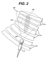
- FIGURE 2 a technique for ultrasonically scanning the left ventricle of the heart is shown.
- the heart 100 shown in partial outline behind the rib cage 110,112 is located behind the left side of the rib cage. Outlined within the heart and cross-hatched is the left ventricle 102 of the heart 100.
- the left ventricle can be accessed for ultrasonic imaging by scanning the heart from between the ribs 110,112 for adult patients and, for some pediatric patients, by scanning upward from below the lowest rib 112.
- the probe 10 scans the heart from the heart apex 104 as indicated by the outline 120 of the image sector scanned by the probe 10.
- the left ventricle 102 can be fully encompasses and scanned by a sector scan directed from between the rib cage 110,112.
- a number of spatially distinct scan planes of the chamber are acquired.
- a number of acquisition techniques are possible.
- One scan plane of the left ventricle 102 chamber is shown in FIGURE 3, located about a centerline 122.
- the transducer probe 10 may be turned about this centerline to acquire a number of angularly disposed scan planes of the left ventricle with a common center axis.
- a group of scan planes acquired in this manner are shown edge-on in FIGURE 4.
- the transducer is automatically turned about a centerline normal to the center of the transducer as can be performed by the transducer probe mechanism described in McCann et al., "Multidimensional Ultrasonic Imaging for Cardiology", Proceedings of the IEEE, vol.
- FIGURE 4 shows a number of ultrasonic scan planes with a common centerline 122 through the left ventricle 102 as scan planes 120.1, 120.2, 120.3, 120.4 ... 120.n.
- each successive scan plane is angularly oriented with respect to adjacent scan planes by about 4° of rotation.
- FIGURE 4 One of the scan planes of FIGURE 4 is depicted in FIGURE 3, containing pixels 130-137' of the blood pool 102 of the left ventricle.
- these pixels are produced by Doppler power imaging of the blood pool of the left ventricle, which advantageously provides highly sensitive, segmented images of the blood pool.
- the image plane pixels are mapped to the voxels of the left ventricle blood pool, and the degree to which they sample the blood pool is noted.
- FIGURE 4 it is seen that the intersection of all of the scan planes at their common centerline 122 (the point of intersection in this drawing) results in relative oversampling of voxels in this region of the left ventricle, as each scan plane contains pixels from along the centerline 122.
- the voxels are relatively undersampled, due to the relatively sizable angular spacing between adjacent scan planes.
- the pixels in the blood pool images are weighted accordingly.
- Such weighting for a plurality of angularly disposed scan planes 120.k, 120.l, and 120.m is illustrated in exaggerated form in FIGURE 4a, where the scan planes are again shown edge-on.
- the pixels which are relatively closely spaced to adjacent scan planes are weighted by a relatively small weighting factor w 1 , illustrated by the small box w 1 .
- More widely separated pixels outwardly spaced from the inner pixels of the scan planes are weighted by increasing weights as shown by the boxes of increasing sizes w 2 and w 3 .
- the pixels are given the greatest weights as indicated by the largest boxes w 4 .
- this weighting scheme results in the pixels (shown as small boxes) located along the centerline of image overlap from pixel 130 through pixel 130' being the most lightly weighted; the next outward rows of pixels, from pixel 133 to pixel 133' and from pixel 132 to pixel 132' are more greatly weighted; and the more outwardly rows of pixels from pixel 136 to pixel 136' and from pixel 137 to pixel 137', are even more greatly weighted.
- the pixels of each plane 120.1 ... 120.n are weighted in accordance with the density with which the voxels of the blood pool are sampled by the chosen inter-plane spacing.
- the weighted pixels of the blood pool are integrated or summed as indicated at 44 to produce a measure of the volume of the blood pool.
- left ventricular ejection fraction two measures of left ventricular volume are made, one at peak systole when the left ventricle is fully contracted, and the other at end diastole when the left ventricle is fully expanded.
- Scan plane acquisition at these times may be performed by heart gated scan plane acquisition using an ECG waveform as shown by the ECG waveform 144 of FIGURE 7. Peak systole occurs each heart cycle at time t s , and end diastole occurs at each time t d .
- Scan planes are acquired at these two times, thereby permitting the acquisition of one scan plane for each scan plane set during each heart cycle.
- several scan planes could be rapidly acquired in succession at each time t s and t d .
- several planes may be acquired at the same orientation at each gated interval and averaged on a frame to frame basis to produce a single scan plane of data with increased immunity to signal dropout.
- two sets of spatially distinct scan planes 120.1 ... 120.n are stored in the frame memory 30 of FIGURE 1, one set being acquired around times t s and the other set being acquired around times t d .
- the blood pool pixels of each set of scan planes are then weighted in accordance with the chamber voxel sampling density and accumulated to produce one measure of left ventricular volume at peak systole and another measure of left ventricular volume and end diastole.
- E.F. Ved - Vps Ved
- Vps the chamber volume measured at peak systole
- FIGURE 5 for example the transducer probe 10 is rocked against the patient's body as indicated by the arrow 140 to fan the scan planes 120.1 ... 120.n over the blood pool 102.
- the scan planes 120.1 ... 120.n in FIGURE 5 are shown edge-on.
- the fan-shaped group of scan planes are again angularly disposed with respect to each other but in a different dimension than the preceding example, and are more widely separated at the right side of the drawing than at the left side.
- the blood pool voxels at the right side (further from the transducer probe) are more widely sampled than are the voxels at the left side (closer to the transducer probe).
- scan plane pixels to the right are more greatly weighted than are pixels to the left, as indicated by the circles w 1 - w 4 , which represent relative pixel weighting.
- ejection fraction measurements two sets of scan planes are acquired, one set at end diastole and another set at peak systole. The weighted pixel values are integrated or summed to produce measures of chamber volume from each scan plane set, and the two measures used in the above expression to compute left ventricular ejection fraction.
- a device for fan scanning a transducer probe is described in U.S. Pat. 5,487,388.
- FIGURE 6a illustrates a blood pool volume 102 which is scanned by a plurality of parallel scan planes 120.1 ... 120.n.
- uniform weighting can be used for the pixels in each scan plane, as the inter-plane spacing between adjacent scan planes is uniform. This is illustrated by the uniformly sized circles 150, representing uniform pixel weights along the scan planes 120.c and 120.d. If the scan planes are parallel but non-uniformly spaced, the pixel weighting can vary from one scan plane to another to compensate for the non-uniform voxel sampling density from plane to plane.
- Trans-thoracic parallel scanning of the chambers of the heart is not easily performed due to the proximity of the rib cage, however, a transducer probe for scanning the heart from the esophagus with a plurality of transversely oriented parallel planes is described in U.S. Pat. 5,295,486.
- FIGURES 6b and 6c illustrate cross-sections 102d and 102j of the left ventricle blood pool of scan planes 120.d and 120.j, respectively. Since the entire blood pool is roughly cylindrical, more outwardly disposed scan planes will cut through and show ever smaller blood pool areas, as FIGURE 6b and FIGURE 6c demonstrate.
- the pixels 160 and 162 of the respective areas are uniformly weighted since the scan planes in the example are in parallel and uniformly spaced, and the weighted pixels of all of the blood pool areas of the scan planes are integrated or summed to determine a measure of the blood pool volume.
- two sets of scan planes one acquired at peak systole and the other acquired at end diastole, are acquired, the volumes at the two heart phases determined, then used to compute left ventricular ejection fraction.
- Pulse to pulse subtraction as described in U.S. Pat. (appl. SN 08/655,394) may also be employed for detection of the endocardial border of the heart chamber rather than the bloodflow contained within the chamber. A number of spatially distinct scan planes of the chamber border are acquired, then pixels or segments of the border weighted in accordance with the density with which areas of the endocardial wall are sampled, the inter-plane spacing at the heart wall. Accumulating these weighted values will also provide a measure of the heart chamber volume, and such measures can be used to compute ejection fraction as described above.
- the techniques of the present invention may be enhanced through the use of ultrasonic contrast agents, enabling high sensitivity contrast agent detection within the heart chambers as described in U.S. Pat. 5,456,257 or by ultrasonic Doppler techniques. Harmonic contrast agents are especially advantageous, as they will afford good echo sensitivity even under the low flow conditions often present at end diastole and peak systole.
- volume measurement technique of the present invention may be used to measure the volume of other chambers of the heart and can be extended to measure the volume of any fluid filled vessel or organ of the body.
Abstract
Description
Claims (22)
- An ultrasonic diagnostic imaging system for measuring the volume of a chamber of the heart, comprising:an ultrasonic transducer probe for scanning the heart at different scan plane orientations;means for storing a plurality of spatially distinct scan planes containing ultrasonic data of the same chamber of the heart;means for combining said ultrasonic data from said scan planes to develop a measure of the volume of said chamber of the heart; andmeans for displaying cardiac diagnostic information derived from said measure.
- The ultrasonic diagnostic imaging system of Claim 1, wherein said ultrasonic data comprises ultrasonic Doppler data.
- The ultrasonic diagnostic imaging system of Claim 2, wherein said ultrasonic Doppler data comprises ultrasonic power Doppler data.
- The ultrasonic diagnostic imaging system of Claim 1, wherein said combining means further includes means for weighting the ultrasonic data of a scan plane in accordance with the sampling density of the chamber afforded by said scan planes.
- The ultrasonic diagnostic imaging system of Claim 4, wherein said means for weighting comprises means for weighting the ultrasonic data of a scan plane in accordance with the inter-plane spacing of said scan planes.
- The ultrasonic diagnostic imaging system of Claim 1, wherein said ultrasonic data comprises image pixel data, and wherein said combining means further includes means for weighting the pixel data of a scan plane in accordance with the sampling density of the chamber afforded by said scan planes.
- The ultrasonic diagnostic imaging system of Claim 6, wherein said means for weighting comprises means for weighting the pixel data of a scan plane in accordance with the inter-plane spacing of said scan planes.
- The ultrasonic diagnostic imaging system of Claim 1, further including heart gating means for scanning the heart at a desired phase of the heart cycle.
- The ultrasonic diagnostic imaging system of Claim 8, wherein said plurality of spatially distinct scan planes are acquired at substantially the same phase of the heart cycle.
- The ultrasonic diagnostic imaging system of Claim 9, wherein said means for displaying cardiac diagnostic information further includes means for computing ejection fraction from said volume measure.
- The ultrasonic diagnostic imaging system of Claim 9, wherein said means for storing comprises means for storing two groups of spatially distinct scan planes, each acquired at a different phase of the heart cycle; said combining means comprises means for developing a measure of the volume of a chamber from each of said groups of scan planes; and said means for displaying cardiac diagnostic information further includes means for computing ejection fraction from said volume measures.
- An ultrasonic diagnostic imaging system for measuring the volume of a chamber of the heart, comprising:an ultrasonic transducer probe for scanning the heart at different scan plane orientations;means for storing a plurality of spatially distinct scan planes containing ultrasonic data of the same chamber of the heart;means for delineating endocardial border data of said chamber in said scan planes;means for weighting said delineated endocardial border data in accordance with the sampling density of the endocardium afforded by said scan planes; andmeans for combining said weighted endocardial border data to develop a measure of the volume of said chamber.
- The ultrasonic diagnostic imaging system of Claim 12, wherein said means for weighting comprises means for weighting the delineated endocardial border data of a scan plane in accordance with the inter-plane spacing of said scan planes.
- An ultrasonic diagnostic imaging system for measuring the volume of a vessel or organ of the body, comprising:an ultrasonic transducer probe for scanning the vessel or organ at different scan plane orientations;means for storing a plurality of spatially distinct scan planes containing ultrasonic data of said vessel or organ;means for weighting the ultrasonic data of a scan plane in accordance with the sampling density of the interior of said vessel or organ afforded by said scan planes; andmeans for combining said weighted ultrasonic data from said scan planes to develop a measure of the volume of said vessel or organ.
- The ultrasonic diagnostic imaging system of Claim 14, wherein said ultrasonic data comprises ultrasonic Doppler data.
- The ultrasonic diagnostic imaging system of Claim 15, wherein said ultrasonic Doppler data comprises ultrasonic power Doppler data.
- A method for measuring the volume of a chamber of a heart containing an ultrasonic contrast agent comprising the steps of:scanning the heart chamber at different scan plane orientations;storing a plurality of spatially distinct scan planes containing ultrasonic data derived from ultrasonic signals received from contrast agent in said chamber of the heart; andcombining said ultrasonic data from said scan planes to develop a measure of the volume of said chamber of the heart.
- The method of Claim 17, wherein said ultrasonic contrast agent comprises a harmonic ultrasonic contrast agent.
- An ultrasonic diagnostic imaging system for measuring the volume of a chamber of the heart, comprising:an ultrasonic transducer probe for scanning the heart at different scan plane orientations which share a common scanline orientation;means for storing a plurality of spatially distinct scan planes containing ultrasonic data of the same chamber of the heart; andmeans for combining said ultrasonic data from said scan planes to develop a measure of the volume of said chamber of the heart.
- An ultrasonic diagnostic imaging system for measuring the volume of a chamber of the heart, comprising:an ultrasonic transducer probe for scanning the heart at different scan plane orientations which are angularly inclined with respect to one another;means for storing a plurality of spatially distinct scan planes containing ultrasonic data of the same chamber of the heart; andmeans for combining said ultrasonic data from said scan planes to develop a measure of the volume of said chamber of the heart.
- An ultrasonic diagnostic imaging system for measuring the volume of a chamber of the heart, comprising:an ultrasonic transducer probe for scanning the heart at different scan plane orientations which are parallel to one another;means for storing a plurality of spatially distinct scan planes containing ultrasonic data of the same chamber of the heart; andmeans for combining said ultrasonic data from said scan planes to develop a measure of the volume of said chamber of the heart.
- The ultrasonic diagnostic imaging system of Claim 21, further comprising means for weighting said ultrasonic data of said scan planes in accordance with the separation of adjacent scan planes; and wherein said means for combining comprises means for combining said weighted ultrasonic data.
Applications Claiming Priority (2)
| Application Number | Priority Date | Filing Date | Title |
|---|---|---|---|
| US08/747,100 US5846200A (en) | 1996-11-08 | 1996-11-08 | Ultrasonic diagnostic imaging system for analysis of left ventricular function |
| US747100 | 2000-12-21 |
Publications (3)
| Publication Number | Publication Date |
|---|---|
| EP0846442A2 true EP0846442A2 (en) | 1998-06-10 |
| EP0846442A3 EP0846442A3 (en) | 1999-05-06 |
| EP0846442B1 EP0846442B1 (en) | 2005-09-21 |
Family
ID=25003658
Family Applications (1)
| Application Number | Title | Priority Date | Filing Date |
|---|---|---|---|
| EP97308966A Expired - Lifetime EP0846442B1 (en) | 1996-11-08 | 1997-11-07 | Ultrasonic diagnostic imaging system |
Country Status (7)
| Country | Link |
|---|---|
| US (1) | US5846200A (en) |
| EP (1) | EP0846442B1 (en) |
| JP (1) | JPH10262975A (en) |
| KR (1) | KR100491623B1 (en) |
| CA (1) | CA2217256A1 (en) |
| DE (1) | DE69734230T2 (en) |
| NO (1) | NO975110L (en) |
Cited By (5)
| Publication number | Priority date | Publication date | Assignee | Title |
|---|---|---|---|---|
| US5924991A (en) * | 1997-08-22 | 1999-07-20 | Acuson Corporation | Ultrasonic system and method for harmonic imaging in three dimensions |
| US6122222A (en) * | 1995-03-02 | 2000-09-19 | Acuson Corporation | Ultrasonic transmit and receive system |
| EP1596718A2 (en) * | 2002-11-05 | 2005-11-23 | Diagnostic Ultrasound Corporation | 3d ultrasound-based instrument for non-invasive measurement of amniotic fluid volume |
| WO2017144851A1 (en) * | 2016-02-24 | 2017-08-31 | King's College London | Measurement of cardiac first phase ejection fraction |
| US10914826B2 (en) | 2008-06-26 | 2021-02-09 | Verasonics, Inc. | High frame rate quantitative doppler flow imaging using unfocused transmit beams |
Families Citing this family (28)
| Publication number | Priority date | Publication date | Assignee | Title |
|---|---|---|---|---|
| EP1118009A1 (en) * | 1998-09-28 | 2001-07-25 | Nycomed Imaging As | Method of magnetic resonance imaging |
| US7837624B1 (en) * | 1998-11-20 | 2010-11-23 | Siemens Medical Solutions Usa, Inc. | Medical diagnostic ultrasound imaging methods for extended field of view |
| US6535623B1 (en) * | 1999-04-15 | 2003-03-18 | Allen Robert Tannenbaum | Curvature based system for the segmentation and analysis of cardiac magnetic resonance images |
| US9572519B2 (en) | 1999-05-18 | 2017-02-21 | Mediguide Ltd. | Method and apparatus for invasive device tracking using organ timing signal generated from MPS sensors |
| US7386339B2 (en) * | 1999-05-18 | 2008-06-10 | Mediguide Ltd. | Medical imaging and navigation system |
| US8442618B2 (en) * | 1999-05-18 | 2013-05-14 | Mediguide Ltd. | Method and system for delivering a medical device to a selected position within a lumen |
| US7343195B2 (en) * | 1999-05-18 | 2008-03-11 | Mediguide Ltd. | Method and apparatus for real time quantitative three-dimensional image reconstruction of a moving organ and intra-body navigation |
| US7778688B2 (en) | 1999-05-18 | 2010-08-17 | MediGuide, Ltd. | System and method for delivering a stent to a selected position within a lumen |
| US9833167B2 (en) | 1999-05-18 | 2017-12-05 | Mediguide Ltd. | Method and system for superimposing virtual anatomical landmarks on an image |
| US7840252B2 (en) | 1999-05-18 | 2010-11-23 | MediGuide, Ltd. | Method and system for determining a three dimensional representation of a tubular organ |
| US6249693B1 (en) * | 1999-11-01 | 2001-06-19 | General Electric Company | Method and apparatus for cardiac analysis using four-dimensional connectivity and image dilation |
| US6503199B1 (en) | 1999-11-03 | 2003-01-07 | Atl Ultrasound | Uniform volumetric scanning ultrasonic diagnostic imaging system |
| US6512943B1 (en) | 2000-05-22 | 2003-01-28 | Wisconsin Alumni Research Foundation | Combined ultrasound-radionuclide device for percutaneous ultrasound-guided biopsy and method of use |
| US6468216B1 (en) * | 2000-08-24 | 2002-10-22 | Kininklijke Philips Electronics N.V. | Ultrasonic diagnostic imaging of the coronary arteries |
| US6592518B2 (en) * | 2001-04-05 | 2003-07-15 | Kenergy, Inc. | Cardiac monitoring system and method with multiple implanted transponders |
| JP2002306477A (en) * | 2001-04-11 | 2002-10-22 | Ge Medical Systems Global Technology Co Llc | Method and apparatus for transmitting and receiving ultrasonic waves, and method and apparatus for ultrasonic photographing using the same |
| JP2003010182A (en) * | 2001-06-19 | 2003-01-14 | Ge Medical Systems Global Technology Co Llc | Ultrasonographic method and ultrasonographic device |
| US7397937B2 (en) * | 2001-11-23 | 2008-07-08 | R2 Technology, Inc. | Region growing in anatomical images |
| US6547735B1 (en) | 2001-12-05 | 2003-04-15 | Koninklijke Philips Electronics N.V. | Partial rayline volumetric scanning ultrasonic diagnostic imaging system |
| US6723050B2 (en) | 2001-12-19 | 2004-04-20 | Koninklijke Philips Electronics N.V. | Volume rendered three dimensional ultrasonic images with polar coordinates |
| IL148299A (en) * | 2002-02-21 | 2014-04-30 | Technion Res & Dev Foundation | Ultrasound cardiac stimulator |
| US6824517B2 (en) * | 2002-06-25 | 2004-11-30 | Koninklijke Philips Electronics N.V. | Ultrasound quantification in real-time using acoustic data in more than two dimensions |
| US7505809B2 (en) * | 2003-01-13 | 2009-03-17 | Mediguide Ltd. | Method and system for registering a first image with a second image relative to the body of a patient |
| US8900149B2 (en) * | 2004-04-02 | 2014-12-02 | Teratech Corporation | Wall motion analyzer |
| US20090156933A1 (en) * | 2005-09-07 | 2009-06-18 | Koninklijke Philips Electronics, N.V. | Ultrasound system for reliable 3d assessment of right ventricle of the heart and method of doing the same |
| CN102551791B (en) * | 2010-12-17 | 2016-04-27 | 深圳迈瑞生物医疗电子股份有限公司 | A kind of ultrasonic imaging method and device |
| CN113597286A (en) * | 2019-03-19 | 2021-11-02 | 皇家飞利浦有限公司 | Three-dimensional volumetric flow quantification and measurement |
| US11678862B2 (en) * | 2019-09-16 | 2023-06-20 | Siemens Medical Solutions Usa, Inc. | Muscle contraction state triggering of quantitative medical diagnostic ultrasound |
Citations (4)
| Publication number | Priority date | Publication date | Assignee | Title |
|---|---|---|---|---|
| US5456257A (en) | 1994-11-23 | 1995-10-10 | Advanced Technology Laboratories, Inc. | Ultrasonic detection of contrast agents |
| US5474073A (en) | 1994-11-22 | 1995-12-12 | Advanced Technology Laboratories, Inc. | Ultrasonic diagnostic scanning for three dimensional display |
| US5485842A (en) | 1994-11-30 | 1996-01-23 | Advanced Technology Laboratories, Inc. | Ultrasonic diagnostic scan conversion for three dimensional display processing |
| US5487388A (en) | 1994-11-01 | 1996-01-30 | Interspec. Inc. | Three dimensional ultrasonic scanning devices and techniques |
Family Cites Families (18)
| Publication number | Priority date | Publication date | Assignee | Title |
|---|---|---|---|---|
| US4341120A (en) * | 1979-11-09 | 1982-07-27 | Diasonics Cardio/Imaging, Inc. | Ultrasonic volume measuring system |
| DE3914619A1 (en) * | 1989-05-03 | 1990-11-08 | Kontron Elektronik | DEVICE FOR TRANSOESOPHAGEAL ECHOCARDIOGRAPHY |
| IL91803A0 (en) * | 1989-09-27 | 1990-06-10 | Andre F Stupnicki | Method and apparatus for reliable measurement of cardiac power index |
| US5056526A (en) * | 1989-10-27 | 1991-10-15 | Khalil Hassan H | Device for global evaluation of the left ventricular ejection fraction by thermodilution |
| US5211169A (en) * | 1990-11-08 | 1993-05-18 | Prism Imaging, Inc. | Blood pool imaging and analysis technique using ultrasound |
| US5195521A (en) * | 1990-11-09 | 1993-03-23 | Hewlett-Packard Company | Tissue measurements |
| US5181514A (en) * | 1991-05-21 | 1993-01-26 | Hewlett-Packard Company | Transducer positioning system |
| US5302372A (en) * | 1992-07-27 | 1994-04-12 | National Science Council | Method to opacify left ventricle in echocardiography |
| US5379769A (en) * | 1992-11-30 | 1995-01-10 | Hitachi Medical Corporation | Ultrasonic diagnostic apparatus for displaying an image in a three-dimensional image and in a real time image and a display method thereof |
| US5322067A (en) * | 1993-02-03 | 1994-06-21 | Hewlett-Packard Company | Method and apparatus for determining the volume of a body cavity in real time |
| US5460181A (en) * | 1994-10-06 | 1995-10-24 | Hewlett Packard Co. | Ultrasonic transducer for three dimensional imaging |
| US5435310A (en) * | 1993-06-23 | 1995-07-25 | University Of Washington | Determining cardiac wall thickness and motion by imaging and three-dimensional modeling |
| US5415171A (en) * | 1993-08-09 | 1995-05-16 | Hewlett-Packard Company | Phase imaging and myocardial performance |
| JP3392482B2 (en) * | 1993-11-05 | 2003-03-31 | 株式会社東芝 | Cardiac function test system |
| US5458126A (en) * | 1994-02-24 | 1995-10-17 | General Electric Company | Cardiac functional analysis system employing gradient image segmentation |
| US5465721A (en) * | 1994-04-22 | 1995-11-14 | Hitachi Medical Corporation | Ultrasonic diagnostic apparatus and ultrasonic diagnosis method |
| US5570430A (en) * | 1994-05-31 | 1996-10-29 | University Of Washington | Method for determining the contour of an in vivo organ using multiple image frames of the organ |
| JP3713303B2 (en) * | 1994-06-22 | 2005-11-09 | 株式会社東芝 | Ultrasonic diagnostic equipment |
-
1996
- 1996-11-08 US US08/747,100 patent/US5846200A/en not_active Expired - Fee Related
-
1997
- 1997-09-29 CA CA002217256A patent/CA2217256A1/en not_active Abandoned
- 1997-11-06 KR KR1019970058297A patent/KR100491623B1/en not_active IP Right Cessation
- 1997-11-06 NO NO975110A patent/NO975110L/en not_active Application Discontinuation
- 1997-11-07 DE DE69734230T patent/DE69734230T2/en not_active Expired - Fee Related
- 1997-11-07 EP EP97308966A patent/EP0846442B1/en not_active Expired - Lifetime
- 1997-11-10 JP JP9321968A patent/JPH10262975A/en active Pending
Patent Citations (4)
| Publication number | Priority date | Publication date | Assignee | Title |
|---|---|---|---|---|
| US5487388A (en) | 1994-11-01 | 1996-01-30 | Interspec. Inc. | Three dimensional ultrasonic scanning devices and techniques |
| US5474073A (en) | 1994-11-22 | 1995-12-12 | Advanced Technology Laboratories, Inc. | Ultrasonic diagnostic scanning for three dimensional display |
| US5456257A (en) | 1994-11-23 | 1995-10-10 | Advanced Technology Laboratories, Inc. | Ultrasonic detection of contrast agents |
| US5485842A (en) | 1994-11-30 | 1996-01-23 | Advanced Technology Laboratories, Inc. | Ultrasonic diagnostic scan conversion for three dimensional display processing |
Non-Patent Citations (1)
| Title |
|---|
| MCCANN ET AL.: "Multidimensional Ultrasonic Imaging for Cardiology", PROCEEDINGS OF THE IEEE, vol. 76, no. 6, 1 September 1988 (1988-09-01), pages 1063-73 |
Cited By (10)
| Publication number | Priority date | Publication date | Assignee | Title |
|---|---|---|---|---|
| US6122222A (en) * | 1995-03-02 | 2000-09-19 | Acuson Corporation | Ultrasonic transmit and receive system |
| US5924991A (en) * | 1997-08-22 | 1999-07-20 | Acuson Corporation | Ultrasonic system and method for harmonic imaging in three dimensions |
| US5928151A (en) * | 1997-08-22 | 1999-07-27 | Acuson Corporation | Ultrasonic system and method for harmonic imaging in three dimensions |
| EP1596718A2 (en) * | 2002-11-05 | 2005-11-23 | Diagnostic Ultrasound Corporation | 3d ultrasound-based instrument for non-invasive measurement of amniotic fluid volume |
| EP1596718A4 (en) * | 2002-11-05 | 2006-05-10 | Diagnostic Ultrasound Corp | 3d ultrasound-based instrument for non-invasive measurement of amniotic fluid volume |
| US10914826B2 (en) | 2008-06-26 | 2021-02-09 | Verasonics, Inc. | High frame rate quantitative doppler flow imaging using unfocused transmit beams |
| WO2017144851A1 (en) * | 2016-02-24 | 2017-08-31 | King's College London | Measurement of cardiac first phase ejection fraction |
| CN109414205A (en) * | 2016-02-24 | 2019-03-01 | 顾昊天 | The measurement of heart first stage ejection fraction |
| CN109414205B (en) * | 2016-02-24 | 2021-10-01 | 顾昊天 | Measurement of cardiac first phase ejection fraction |
| US11617515B2 (en) | 2016-02-24 | 2023-04-04 | Haotian GU | Measurement of cardiac first phase ejection fraction |
Also Published As
| Publication number | Publication date |
|---|---|
| US5846200A (en) | 1998-12-08 |
| JPH10262975A (en) | 1998-10-06 |
| EP0846442A3 (en) | 1999-05-06 |
| KR100491623B1 (en) | 2005-09-16 |
| EP0846442B1 (en) | 2005-09-21 |
| KR19980042140A (en) | 1998-08-17 |
| CA2217256A1 (en) | 1998-05-08 |
| DE69734230D1 (en) | 2006-02-02 |
| DE69734230T2 (en) | 2006-06-14 |
| NO975110D0 (en) | 1997-11-06 |
| NO975110L (en) | 1998-05-11 |
Similar Documents
| Publication | Publication Date | Title |
|---|---|---|
| EP0846442B1 (en) | Ultrasonic diagnostic imaging system | |
| US5360006A (en) | Automated method for digital image quantitation | |
| Wigen et al. | 4-D intracardiac ultrasound vector flow imaging–feasibility and comparison to phase-contrast MRI | |
| US6503202B1 (en) | Medical diagnostic ultrasound system and method for flow analysis | |
| Wyatt et al. | Cross-sectional echocardiography. II. Analysis of mathematic models for quantifying volume of the formalin-fixed left ventricle. | |
| US5211169A (en) | Blood pool imaging and analysis technique using ultrasound | |
| US5415171A (en) | Phase imaging and myocardial performance | |
| WO1996041312A1 (en) | Automated method for digital image quantitation | |
| EP0533782B1 (en) | Automated method for digital image quantitation | |
| Berg et al. | Dynamic three-dimensional freehand echocardiography using raw digital ultrasound data | |
| Zwehl et al. | Validation of a computerized edge detection algorithm for quantitative two-dimensional echocardiography. | |
| Stewart et al. | Left ventricular volume calculation with integrated backscatter from echocardiography | |
| US20230134503A1 (en) | Systems and methods for non-invasive pressure measurements | |
| Qin et al. | Determination of left ventricular volume, ejection fraction, and myocardial mass by real‐time three‐dimensional echocardiography | |
| EP1772825A1 (en) | Method for registering images of a sequence of images, particularly ultrasound diagnostic images | |
| JP3035491B2 (en) | Ultrasound diagnostic equipment | |
| JPH11506950A (en) | Automatic Boundary Drawing and Part Dimensioning Using Contrast-Enhanced Imaging | |
| Tanabe et al. | Three‐dimensional echocardiography: Precision and accuracy of left ventricular volume measurement using rotational geometry with variable numbers of slice resolution | |
| Sun et al. | Automated echocardiographic quantification of left ventricular volumes and ejection fraction: validation in the intensive care setting | |
| EP1876567A1 (en) | A method of determining the time dependent behavior of non rigid moving objects, particularly of biological tissues, from echographic ultrasound imaging data | |
| King et al. | A new three-dimensional random scanner for ultrasonic/computer graphic imaging of the heart | |
| Li et al. | Quantification of flow volume with a new digital three‐dimensional color Doppler flow approach: an in vitro study. | |
| US20230240645A1 (en) | Systems and methods for measuring cardiac stiffness | |
| JP3357000B2 (en) | Ultrasound diagnostic equipment | |
| Kuwahara et al. | Ultrasonic Image Processing |
Legal Events
| Date | Code | Title | Description |
|---|---|---|---|
| PUAI | Public reference made under article 153(3) epc to a published international application that has entered the european phase |
Free format text: ORIGINAL CODE: 0009012 |
|
| AK | Designated contracting states |
Kind code of ref document: A2 Designated state(s): DE FR GB IT |
|
| AX | Request for extension of the european patent |
Free format text: AL;LT;LV;MK;RO;SI |
|
| PUAL | Search report despatched |
Free format text: ORIGINAL CODE: 0009013 |
|
| AK | Designated contracting states |
Kind code of ref document: A3 Designated state(s): AT BE CH DE DK ES FI FR GB GR IE IT LI LU MC NL PT SE |
|
| AX | Request for extension of the european patent |
Free format text: AL;LT;LV;MK;RO;SI |
|
| 17P | Request for examination filed |
Effective date: 19991108 |
|
| AKX | Designation fees paid |
Free format text: DE FR GB IT |
|
| 17Q | First examination report despatched |
Effective date: 20030220 |
|
| GRAP | Despatch of communication of intention to grant a patent |
Free format text: ORIGINAL CODE: EPIDOSNIGR1 |
|
| RTI1 | Title (correction) |
Free format text: ULTRASONIC DIAGNOSTIC IMAGING SYSTEM |
|
| GRAS | Grant fee paid |
Free format text: ORIGINAL CODE: EPIDOSNIGR3 |
|
| GRAA | (expected) grant |
Free format text: ORIGINAL CODE: 0009210 |
|
| STAA | Information on the status of an ep patent application or granted ep patent |
Free format text: STATUS: THE PATENT HAS BEEN GRANTED |
|
| AK | Designated contracting states |
Kind code of ref document: B1 Designated state(s): DE FR GB IT |
|
| PG25 | Lapsed in a contracting state [announced via postgrant information from national office to epo] |
Ref country code: IT Free format text: LAPSE BECAUSE OF FAILURE TO SUBMIT A TRANSLATION OF THE DESCRIPTION OR TO PAY THE FEE WITHIN THE PRESCRIBED TIME-LIMIT;WARNING: LAPSES OF ITALIAN PATENTS WITH EFFECTIVE DATE BEFORE 2007 MAY HAVE OCCURRED AT ANY TIME BEFORE 2007. THE CORRECT EFFECTIVE DATE MAY BE DIFFERENT FROM THE ONE RECORDED. Effective date: 20050921 |
|
| REG | Reference to a national code |
Ref country code: GB Ref legal event code: FG4D |
|
| REF | Corresponds to: |
Ref document number: 69734230 Country of ref document: DE Date of ref document: 20051027 Kind code of ref document: P |
|
| REG | Reference to a national code |
Ref country code: GB Ref legal event code: 746 Effective date: 20051031 |
|
| REF | Corresponds to: |
Ref document number: 69734230 Country of ref document: DE Date of ref document: 20060202 Kind code of ref document: P |
|
| PLBE | No opposition filed within time limit |
Free format text: ORIGINAL CODE: 0009261 |
|
| 26N | No opposition filed |
Effective date: 20060622 |
|
| PG25 | Lapsed in a contracting state [announced via postgrant information from national office to epo] |
Ref country code: FR Free format text: LAPSE BECAUSE OF FAILURE TO SUBMIT A TRANSLATION OF THE DESCRIPTION OR TO PAY THE FEE WITHIN THE PRESCRIBED TIME-LIMIT Effective date: 20061020 |
|
| EN | Fr: translation not filed | ||
| PGFP | Annual fee paid to national office [announced via postgrant information from national office to epo] |
Ref country code: GB Payment date: 20061127 Year of fee payment: 10 |
|
| PGFP | Annual fee paid to national office [announced via postgrant information from national office to epo] |
Ref country code: DE Payment date: 20070110 Year of fee payment: 10 |
|
| GBPC | Gb: european patent ceased through non-payment of renewal fee |
Effective date: 20071107 |
|
| PG25 | Lapsed in a contracting state [announced via postgrant information from national office to epo] |
Ref country code: FR Free format text: LAPSE BECAUSE OF FAILURE TO SUBMIT A TRANSLATION OF THE DESCRIPTION OR TO PAY THE FEE WITHIN THE PRESCRIBED TIME-LIMIT Effective date: 20051130 |
|
| PG25 | Lapsed in a contracting state [announced via postgrant information from national office to epo] |
Ref country code: DE Free format text: LAPSE BECAUSE OF NON-PAYMENT OF DUE FEES Effective date: 20080603 |
|
| PG25 | Lapsed in a contracting state [announced via postgrant information from national office to epo] |
Ref country code: FR Free format text: LAPSE BECAUSE OF FAILURE TO SUBMIT A TRANSLATION OF THE DESCRIPTION OR TO PAY THE FEE WITHIN THE PRESCRIBED TIME-LIMIT Effective date: 20050921 |
|
| PG25 | Lapsed in a contracting state [announced via postgrant information from national office to epo] |
Ref country code: GB Free format text: LAPSE BECAUSE OF NON-PAYMENT OF DUE FEES Effective date: 20071107 |