EP0881786A2 - Method and apparatus for transmitting two parallel channels using code division - Google Patents
Method and apparatus for transmitting two parallel channels using code division Download PDFInfo
- Publication number
- EP0881786A2 EP0881786A2 EP98304282A EP98304282A EP0881786A2 EP 0881786 A2 EP0881786 A2 EP 0881786A2 EP 98304282 A EP98304282 A EP 98304282A EP 98304282 A EP98304282 A EP 98304282A EP 0881786 A2 EP0881786 A2 EP 0881786A2
- Authority
- EP
- European Patent Office
- Prior art keywords
- channel
- data related
- spreading
- power level
- spread
- Prior art date
- Legal status (The legal status is an assumption and is not a legal conclusion. Google has not performed a legal analysis and makes no representation as to the accuracy of the status listed.)
- Granted
Links
Images


Classifications
-
- H—ELECTRICITY
- H04—ELECTRIC COMMUNICATION TECHNIQUE
- H04W—WIRELESS COMMUNICATION NETWORKS
- H04W52/00—Power management, e.g. TPC [Transmission Power Control], power saving or power classes
- H04W52/04—TPC
- H04W52/30—TPC using constraints in the total amount of available transmission power
-
- H—ELECTRICITY
- H03—ELECTRONIC CIRCUITRY
- H03M—CODING; DECODING; CODE CONVERSION IN GENERAL
- H03M7/00—Conversion of a code where information is represented by a given sequence or number of digits to a code where the same, similar or subset of information is represented by a different sequence or number of digits
- H03M7/30—Compression; Expansion; Suppression of unnecessary data, e.g. redundancy reduction
- H03M7/40—Conversion to or from variable length codes, e.g. Shannon-Fano code, Huffman code, Morse code
- H03M7/4006—Conversion to or from arithmetic code
-
- H—ELECTRICITY
- H04—ELECTRIC COMMUNICATION TECHNIQUE
- H04B—TRANSMISSION
- H04B1/00—Details of transmission systems, not covered by a single one of groups H04B3/00 - H04B13/00; Details of transmission systems not characterised by the medium used for transmission
- H04B1/69—Spread spectrum techniques
- H04B1/707—Spread spectrum techniques using direct sequence modulation
-
- H—ELECTRICITY
- H04—ELECTRIC COMMUNICATION TECHNIQUE
- H04B—TRANSMISSION
- H04B10/00—Transmission systems employing electromagnetic waves other than radio-waves, e.g. infrared, visible or ultraviolet light, or employing corpuscular radiation, e.g. quantum communication
- H04B10/25—Arrangements specific to fibre transmission
- H04B10/2575—Radio-over-fibre, e.g. radio frequency signal modulated onto an optical carrier
- H04B10/25752—Optical arrangements for wireless networks
- H04B10/25753—Distribution optical network, e.g. between a base station and a plurality of remote units
- H04B10/25754—Star network topology
-
- H—ELECTRICITY
- H04—ELECTRIC COMMUNICATION TECHNIQUE
- H04B—TRANSMISSION
- H04B7/00—Radio transmission systems, i.e. using radiation field
- H04B7/24—Radio transmission systems, i.e. using radiation field for communication between two or more posts
- H04B7/26—Radio transmission systems, i.e. using radiation field for communication between two or more posts at least one of which is mobile
- H04B7/2628—Radio transmission systems, i.e. using radiation field for communication between two or more posts at least one of which is mobile using code-division multiple access [CDMA] or spread spectrum multiple access [SSMA]
-
- H—ELECTRICITY
- H04—ELECTRIC COMMUNICATION TECHNIQUE
- H04J—MULTIPLEX COMMUNICATION
- H04J13/00—Code division multiplex systems
- H04J13/0003—Code application, i.e. aspects relating to how codes are applied to form multiplexed channels
-
- H—ELECTRICITY
- H04—ELECTRIC COMMUNICATION TECHNIQUE
- H04J—MULTIPLEX COMMUNICATION
- H04J13/00—Code division multiplex systems
- H04J13/0077—Multicode, e.g. multiple codes assigned to one user
-
- H—ELECTRICITY
- H04—ELECTRIC COMMUNICATION TECHNIQUE
- H04J—MULTIPLEX COMMUNICATION
- H04J13/00—Code division multiplex systems
- H04J13/16—Code allocation
-
- H—ELECTRICITY
- H04—ELECTRIC COMMUNICATION TECHNIQUE
- H04L—TRANSMISSION OF DIGITAL INFORMATION, e.g. TELEGRAPHIC COMMUNICATION
- H04L51/00—User-to-user messaging in packet-switching networks, transmitted according to store-and-forward or real-time protocols, e.g. e-mail
- H04L51/48—Message addressing, e.g. address format or anonymous messages, aliases
-
- H—ELECTRICITY
- H04—ELECTRIC COMMUNICATION TECHNIQUE
- H04L—TRANSMISSION OF DIGITAL INFORMATION, e.g. TELEGRAPHIC COMMUNICATION
- H04L51/00—User-to-user messaging in packet-switching networks, transmitted according to store-and-forward or real-time protocols, e.g. e-mail
- H04L51/58—Message adaptation for wireless communication
-
- H—ELECTRICITY
- H04—ELECTRIC COMMUNICATION TECHNIQUE
- H04L—TRANSMISSION OF DIGITAL INFORMATION, e.g. TELEGRAPHIC COMMUNICATION
- H04L65/00—Network arrangements, protocols or services for supporting real-time applications in data packet communication
- H04L65/1066—Session management
- H04L65/1101—Session protocols
- H04L65/1104—Session initiation protocol [SIP]
-
- H—ELECTRICITY
- H04—ELECTRIC COMMUNICATION TECHNIQUE
- H04N—PICTORIAL COMMUNICATION, e.g. TELEVISION
- H04N19/00—Methods or arrangements for coding, decoding, compressing or decompressing digital video signals
- H04N19/10—Methods or arrangements for coding, decoding, compressing or decompressing digital video signals using adaptive coding
- H04N19/102—Methods or arrangements for coding, decoding, compressing or decompressing digital video signals using adaptive coding characterised by the element, parameter or selection affected or controlled by the adaptive coding
- H04N19/103—Selection of coding mode or of prediction mode
- H04N19/109—Selection of coding mode or of prediction mode among a plurality of temporal predictive coding modes
-
- H—ELECTRICITY
- H04—ELECTRIC COMMUNICATION TECHNIQUE
- H04N—PICTORIAL COMMUNICATION, e.g. TELEVISION
- H04N19/00—Methods or arrangements for coding, decoding, compressing or decompressing digital video signals
- H04N19/10—Methods or arrangements for coding, decoding, compressing or decompressing digital video signals using adaptive coding
- H04N19/134—Methods or arrangements for coding, decoding, compressing or decompressing digital video signals using adaptive coding characterised by the element, parameter or criterion affecting or controlling the adaptive coding
- H04N19/136—Incoming video signal characteristics or properties
- H04N19/137—Motion inside a coding unit, e.g. average field, frame or block difference
- H04N19/139—Analysis of motion vectors, e.g. their magnitude, direction, variance or reliability
-
- H—ELECTRICITY
- H04—ELECTRIC COMMUNICATION TECHNIQUE
- H04N—PICTORIAL COMMUNICATION, e.g. TELEVISION
- H04N19/00—Methods or arrangements for coding, decoding, compressing or decompressing digital video signals
- H04N19/60—Methods or arrangements for coding, decoding, compressing or decompressing digital video signals using transform coding
- H04N19/625—Methods or arrangements for coding, decoding, compressing or decompressing digital video signals using transform coding using discrete cosine transform [DCT]
-
- H—ELECTRICITY
- H04—ELECTRIC COMMUNICATION TECHNIQUE
- H04N—PICTORIAL COMMUNICATION, e.g. TELEVISION
- H04N19/00—Methods or arrangements for coding, decoding, compressing or decompressing digital video signals
- H04N19/90—Methods or arrangements for coding, decoding, compressing or decompressing digital video signals using coding techniques not provided for in groups H04N19/10-H04N19/85, e.g. fractals
- H04N19/91—Entropy coding, e.g. variable length coding [VLC] or arithmetic coding
-
- H—ELECTRICITY
- H04—ELECTRIC COMMUNICATION TECHNIQUE
- H04W—WIRELESS COMMUNICATION NETWORKS
- H04W4/00—Services specially adapted for wireless communication networks; Facilities therefor
- H04W4/12—Messaging; Mailboxes; Announcements
- H04W4/14—Short messaging services, e.g. short message services [SMS] or unstructured supplementary service data [USSD]
-
- H—ELECTRICITY
- H04—ELECTRIC COMMUNICATION TECHNIQUE
- H04W—WIRELESS COMMUNICATION NETWORKS
- H04W76/00—Connection management
- H04W76/10—Connection setup
- H04W76/12—Setup of transport tunnels
-
- H—ELECTRICITY
- H04—ELECTRIC COMMUNICATION TECHNIQUE
- H04L—TRANSMISSION OF DIGITAL INFORMATION, e.g. TELEGRAPHIC COMMUNICATION
- H04L51/00—User-to-user messaging in packet-switching networks, transmitted according to store-and-forward or real-time protocols, e.g. e-mail
- H04L51/04—Real-time or near real-time messaging, e.g. instant messaging [IM]
-
- H—ELECTRICITY
- H04—ELECTRIC COMMUNICATION TECHNIQUE
- H04L—TRANSMISSION OF DIGITAL INFORMATION, e.g. TELEGRAPHIC COMMUNICATION
- H04L65/00—Network arrangements, protocols or services for supporting real-time applications in data packet communication
- H04L65/10—Architectures or entities
- H04L65/1016—IP multimedia subsystem [IMS]
-
- H—ELECTRICITY
- H04—ELECTRIC COMMUNICATION TECHNIQUE
- H04W—WIRELESS COMMUNICATION NETWORKS
- H04W4/00—Services specially adapted for wireless communication networks; Facilities therefor
- H04W4/12—Messaging; Mailboxes; Announcements
-
- H—ELECTRICITY
- H04—ELECTRIC COMMUNICATION TECHNIQUE
- H04W—WIRELESS COMMUNICATION NETWORKS
- H04W72/00—Local resource management
- H04W72/20—Control channels or signalling for resource management
- H04W72/23—Control channels or signalling for resource management in the downlink direction of a wireless link, i.e. towards a terminal
-
- H—ELECTRICITY
- H04—ELECTRIC COMMUNICATION TECHNIQUE
- H04W—WIRELESS COMMUNICATION NETWORKS
- H04W8/00—Network data management
- H04W8/26—Network addressing or numbering for mobility support
-
- H—ELECTRICITY
- H04—ELECTRIC COMMUNICATION TECHNIQUE
- H04W—WIRELESS COMMUNICATION NETWORKS
- H04W88/00—Devices specially adapted for wireless communication networks, e.g. terminals, base stations or access point devices
- H04W88/08—Access point devices
- H04W88/085—Access point devices with remote components
-
- Y—GENERAL TAGGING OF NEW TECHNOLOGICAL DEVELOPMENTS; GENERAL TAGGING OF CROSS-SECTIONAL TECHNOLOGIES SPANNING OVER SEVERAL SECTIONS OF THE IPC; TECHNICAL SUBJECTS COVERED BY FORMER USPC CROSS-REFERENCE ART COLLECTIONS [XRACs] AND DIGESTS
- Y10—TECHNICAL SUBJECTS COVERED BY FORMER USPC
- Y10S—TECHNICAL SUBJECTS COVERED BY FORMER USPC CROSS-REFERENCE ART COLLECTIONS [XRACs] AND DIGESTS
- Y10S370/00—Multiplex communications
- Y10S370/901—Wide area network
- Y10S370/902—Packet switching
- Y10S370/903—Osi compliant network
- Y10S370/906—Fiber data distribution interface, FDDI
-
- Y—GENERAL TAGGING OF NEW TECHNOLOGICAL DEVELOPMENTS; GENERAL TAGGING OF CROSS-SECTIONAL TECHNOLOGIES SPANNING OVER SEVERAL SECTIONS OF THE IPC; TECHNICAL SUBJECTS COVERED BY FORMER USPC CROSS-REFERENCE ART COLLECTIONS [XRACs] AND DIGESTS
- Y10—TECHNICAL SUBJECTS COVERED BY FORMER USPC
- Y10S—TECHNICAL SUBJECTS COVERED BY FORMER USPC CROSS-REFERENCE ART COLLECTIONS [XRACs] AND DIGESTS
- Y10S370/00—Multiplex communications
- Y10S370/901—Wide area network
- Y10S370/902—Packet switching
- Y10S370/903—Osi compliant network
- Y10S370/907—Synchronous optical network, SONET
Definitions
- the invention relates in general to the transmission of parallel channels in a code division multiple access system.
- the invention relates to the transmission of two channels the data communications requirements of which differ from each other as regards e.g. the amount of data transmitted or data integrity.
- terminals such as mobile phones, in cellular radio systems need to transmit both payload, or user, data and various control data which there are usually considerably less than user data or which have different quality requirements as regards the integrity of transmitted information.
- Control and user data are transferred in logically separate channels and it is known several methods for multiplexing those channels into a common physical radio-frequency channel. It is usual to arrange the information transmitted by a radio apparatus into frames in which the control data and user data are located in temporally separable frame components, i.e. multiplexed in the time domain.
- This kind of transmission method is poorly suited to so-called discontinuous transmission (DTX) if the transmission of control data has to be continuous because of the nature of said data.
- DTX discontinuous transmission
- discontinuous transmission the transmission of user data is interrupted for the moments when there is no actual information to be sent (e.g., when the user of a mobile phone stops talking during a call).
- CDMA code division multiple access
- Fig. 1 In systems employing code division multiple access it is known to process control data and user data in two different code channels as shown in Fig. 1. At the same time, Fig. 1 also shows other known ways to combine different logic channels in one transmission.
- the arrangement according to Fig. 1 is known e.g. from patent document Fl 97837 which has the same applicant as this patent application.
- Line 10 represents a transmitted bit stream which is not very error critical but in which a maximum of 10 -3 bit error ratio (BER) is allowed
- line 11 represents an error critical bit stream in which the BER has to be smaller than 10 -6 .
- the bit stream of line 11 is Reed-Solomon coded in block 12 and interleaved in block 13.
- Bit streams from lines 10 and 11 are combined in block 14 and certain tail bits are added to them in block 15 whereafter the resulting combined bit stream is convolution coded in block 16.
- Line 18, the bit stream of which is not error correction coded nor convolution coded, is then multiplexed in block 17 onto the same code channel.
- symbol repetition in block 19 and interleaving in block 20 are used if necessary.
- Spreading is carried out in a coding element 21 using PN1 code, whereafter the resulting symbol stream is taken to the I branch of a radio-frequency block 22 to produce a radio-frequency transmission together with the lower code channel, to be taken to an antenna 23.
- Frame control header (FCH) bits carrying information on the lower code channel are taken via line 24 to a coding block 25 and therefrom via symbol repetition 26 and interleaving 27 to block 28 where reference symbols 29 needed for synchronising the receiver as well as the power control (PC) symbols 30 are added to the symbol stream.
- a coding element 31 performs spreading using PN2 code, which is different from the aforementioned PN1, whereafter the timing of the lower code channel with respect to the higher one is adjusted suitable by a delay element 32 before the symbol stream is taken to the Q branch of the radio-frequency block 22 to produce a radio-frequency transmission together with the higher code channel, to be taken to an antenna 23.
- the delay generated by the delay element 32 may also be 0, in which case quadrature phase shift keying (QPSK) modulation is used.
- QPSK quadrature phase shift keying
- a radio apparatus In a radio apparatus according to Fig. 1, it is possible to use on the lower code channel, due to a lower bit rate, a lower power level than on the higher code channel, thus saving electric power.
- power saving in transmission is advantageous both to lengthen the discharge time of the batteries and to limit the general noise level of the system.
- the arrangement according to Fig. 1 is not optimal from the standpoint of using different power levels because of a power amplifier (not shown) in the radio-frequency block 21 and distortion occurring in it. RF amplifiers do not behave in a linear fashion when operated near the saturation region of the amplifier.
- the inter-modulation products generated in the amplifier should be reduced by operating the amplifier in a so-called backed-off mode, which means the amplifier input power must be decreased compared to the power that would drive the amplifier into saturation.
- the resulting decrease in output power is called the output back-off (OBO).
- OBO output back-off
- the OBO is proportional to the power difference of the code channels so that decreasing the power level of the lower code channel with respect to the power level of the higher code channel increases the OBO.
- the present invention aims to provide a method and apparatus for transmitting two parallel logic channels using code division with improved efficiency vis-à-vis the prior art.
- the present invention resides in using for the logic channels two spreading codes and in the radio-frequency part an IQ modulation method wherein the signal of the first branch is produced as the sum of the spread signals of the different channels, and the signal of the second branch is produced as the difference of the spread signals of the different channels.
- a communications device comprises
- the invention includes a communications system in which at least one transmitter apparatus meets the characteristics listed above.
- the method according to the invention for coding two channels uses two spreading codes such that the bit streams of both channels are spread separately using a first code and a second code.
- the first channel spread with the first code and the second channel spread with the second code are subtracted from each other, and the first channel spread with the second code and the second channel spread with the first code are added up.
- the spread forms of the second channel Prior to said summing and subtraction operations the spread forms of the second channel are multiplied by a power correction factor which is a real number coefficient greater than zero.
- Signals obtained from the summing and subtraction operations are taken to the branches of an IQ type radio-frequency part, and the signals obtained from the branches are summed and taken to an antenna to be transmitted.
- bit streams of the channels may be separately coded using e.g. so-called short codes so that the short codes function as spreading codes proper and the first and second codes can be used for signal scrambling.
- Other known operations such as interleaving, error correction coding and grouping, may also be imposed on the bit streams.
- Figs. 2a and 2b show two mutually alternative arrangements according to the invention for transmitting two parallel channels using code division.
- a first channel contains user data and a second channel contains control data.
- the first channel is called a dedicated traffic channel (DTCH) and the second channel, a physical control channel (PCCH).
- DTCH dedicated traffic channel
- PCCH physical control channel
- Names of the channels are exemplary only and do not confine the application of the invention to any particular communications system. For the invention, it is irrelevant what kind of information is transmitted on the channels or how the data transfer requirements of the different channels differ from each other.
- the invention allows dynamic changing of differences between the channels during the operation of the system.
- bit stream of the DTCH channel is taken to the arrangement according to the invention through line 40 and the bit stream of the PCCH channel through line 41.
- Line 42 represents a gain factor G, the meaning of which will be discussed later on.
- a first code, represented by symbol C l is taken to the arrangement through line 43, and a second code, represented by symbol C Q , is taken to the arrangement through line 44.
- Codes C l and C Q can be e.g. long Gold codes, which are known as such and the use of which is known to one skilled in the art e.g. from the document "Coherent Multicode DS-CDMA Mobile Radio Access" by Adachi et al., IEICE Trans. Commun. Vol. E79 B. No 9, September 1996, pp. 1316-1325.
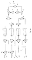
- Fig. 2a shows the spreading of both the DTCH and the PCCH channel using a separate so-called short code prior to other operations related to the coding and modulation.
- the bit stream of the DTCH channel is spread with a short code SC i and in block 46, the bit stream of the PCCH channel is spread with a short code SC j .
- SC i short code
- SC j short code SC j
- the speed of the bit stream on the PCCH channel in bits per second is generally lower than the speed of the bit stream on the DTCH channel.
- the so-called processing gain in block 46 can be higher, i.e. it can employ more symbols per bit stream bit than block 45.
- each terminal can be assigned short codes from among mutually orthogonal or non-orthogonal codes to distinguish between the parallel code channels transmitted by the terminal.
- each terminal needs a short or long code of its own so that a base station receiver can distinguish between signals sent by different terminals.
- each base station can have long codes of its own so that signals sent to terminals within a cell are distinguished using different short codes.
- Associating short codes with blocks 45 and 46 does not limit the invention but also long codes can be used in the spreading represented by these blocks.
- the symbol stream generated in block 45 from the bit stream on the DTCH channel is taken to two parallel branches and further to blocks 47 and 50. If the bit stream on the DTCH channel is spread as shown in block 45 of Fig. 2a, the operations performed on the symbol stream with codes C l and C Q in blocks 47 and 50 are called scrambling. Scrambling can be considered a special case of spreading in which the bandwidth used does not grow any more but in which the data contents of the symbol stream scrambled are divided pseudo-randomly in a manner determined by the (spreading) code used. If spreading according to blocks 45 and 46 is not used, the bit stream of the DTCH channel is taken to blocks 47 and 50 as shown in Fig.
- the PCCH channel bit stream or the symbol stream generated from it in block 46 is taken to two parallel branches in which the bit stream is spread or the symbol stream is scrambled in block 48 with code C Q and in block 49 with code C l .
- Blocks 51, 52, 53 and 54 perform a non-return-to-zero conversion (a phase modulation method) between the bit values included in the symbols generated in the spreading and the corresponding positive or negative values.
- multipliers 55 and 56 the signals carrying the PCCH channel data are multiplied by a gain factor G, whereafter signals to be taken to the I and Q branches of the radio-frequency part are generated in adders 57 and 58.
- the signal taken to the I branch is the difference of the DTCH channel spread with code C l (or spread with code SC i and scrambled with code C l ) and PCCH channel spread with code C Q (or spread with code SC j and scrambled with code C Q ), where the latter is multiplied with the gain factor G.
- the signal taken to the Q branch is the sum of the DTCH channel spread with code C Q (or spread with code SC i and scrambled with code C Q ) and PCCH channel spread with code C l (or spread with code SC j and scrambled with code C l ), where the latter is multiplied with the gain factor G.
- the IQ modulation performed in the radio-frequency part by means of a local oscillator 59, multiplier 60, phase shifter 61 and multiplier 62 is in accordance with the prior art.
- the I and Q branch signals are combined in an adder 63 and taken to an antenna 64 for transmission.
- Multiplying the symbol streams generated from the PCCH channel by a gain factor G unequal to one produces a power difference between the DTCH and PCCH channels. If the gain factor G is between zero and one, the processing gain imposed earlier on in block 46 on the PCCH channel higher than on the DTCH channel, and decreasing of power by gain factor G in blocks 55 and 56 cancel each other out, which means that in the whole arrangement the probable bit error ratio of the PCCH channel remains unchanged even if the power of the channel is reduced by gain factor G. Assuming that the PCCH channel bit stream speed remains constant, the processing gain in block 46 must also remain constant for the symbol rate of the symbol stream generated from the PCCH channel to be the same as on the DTCH channel.
- the gain factor G of the PCCH channel can be used to alter the bit error ratio; if, e.g., it is measured that the bit error ratio in a connection between the transmitting and receiving radio apparatus is too high, the receiving apparatus can request the transmitting apparatus to increase the gain factor G to reduce the bit error ratio. If the bit stream speed on the PCCH channel varies, the communication characteristics on the PCCH channel can be modified in a versatile manner by selecting the processing gain and gain factor G as desired.
- Figs. 2a and 2b do not show any transmitter amplifiers and filters that do not affect the modulation process proper.
- the use and placement of amplifiers and filters in a transmitter apparatus producing code division transmission is generally known so that a person skilled in the art can easily complete the block diagrams of Figs. 2a and 2b where required.
- the spread coding elements, modulating elements, multipliers, adders, oscillator and phase shifter shown in Figs. 2a and 2b are radio-frequency parts which as such are known to one skilled in the art.
- the roles of the adders 57 and 58 are interchangeable, i.e. adder 57 can calculate the sum of the signals brought to it and adder 58 can calculate the difference of the signals brought to it, which as such does not affect the inventional idea realised by the apparatus.
- Figs. 3a, 3b and 3c illustrate constellation points of a phase-modulated radio signal generated by the arrangement according to Fig. 2a or 2b, i.e. possible end points of a vector representing the signal and starting from the origin of an IQ system of coordinates with values 0 (Fig. 3a), 0.5 (Fig. 3b) and 1 (Fig. 3c) for the gain factor G.
- the scales of the I and Q axes are suggestive and represent relative power such that each interval between the scale marks represents the power level of one channel (say, the DTCH channel).
- the coordinates of the constellation points are generally (1+G, 1-G), (1-G, 1+G), (-1+G, 1+G), (-1-G, 1-G), (-1-G, -1+G), (-1+G, -1-G), (1-G, -1+G) and (1+G, -1+G), when the power level of one channel is denoted by 1.
- the gain factor G has the value 0 so that the signal is formed solely on the basis of the DTCH channel.
- Constellation points are reduced to four points which are (1, 1), (-1, 1), (-1, -1) and (1, -1). When the value of the gain factor G starts to grow from zero toward one, each constellation point in the graph of Fig.
- the gain factor G has the value 0.5.
- the constellation points are again reduced in accordance with Fig. 3c to four points which are (2, 0), (0, 2), (-2, 0) and (0, -2).
- the logic for determining the location of the constellation points can easily be generalised to apply to a situation wherein the value of the gain factor G is greater than one.
- Fig. 3b can be understood such that it depicts the location of constellation points generally in a situation in which there is a power difference between the signals representing the data related to the different channels. Then the channel with the lower relative power replaces the PCCH channel in the logic described above and the channel with the higher relative power replaces the DTCH channel.
- the ratio of transmitter peak power to the average power remains almost constant regardless of the power difference between the channels.
- the ratio of the peak power to the average power increases as the power difference increases so that the average power of the transmitter must be decreased lest components transmitted at peak power become distorted because of saturation of transmitter power amplifier. This makes efficiency poorer.
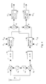
- Fig. 4 is a simple block diagram of a receiver that can be used to receive, demodulate and decode a transmission produced by a transmitter according to Fig. 2a.
- a radio signal received by an antenna 70 is taken to I and Q branches in the receiver where it is down-converted by means of mixers 71 and 72 as well as local oscillator 73 and 90-degree phase shifter 74.
- the resulting signals are A/D converted in blocks 75 and 76, thus producing two parallel symbol streams.
- For despreading the symbol streams are taken to matched filters or correlators 77 and 78, both of which get as input the long spreading codes C l and C Q used by the transmitter.
- the symbol stream decoded with code C l in a first matched filter 77 and the symbol stream decoded with code C Q in a second matched filter 78 are summed in an adder 79, producing a DTCH channel symbol stream which is taken to a matched filter 80 to remove the spreading according to the short code SC i .
- adder 81 calculates the difference of the symbol stream decoded with code C Q in the first matched filter 77 and the symbol stream decoded with code C l in the second matched filter 78, producing a PCCH channel symbol stream which is taken to a matched filter 82 to remove the spreading according to the short code SC j .
- Fig. 4 corresponds to that shown in Fig. 2a in that Fig. 4 does not show the transmitters and filters which as such are obvious to a person skilled in the art and which are of no significance to the demodulation and decoding process proper. If the transmitter is in accordance with Fig. 2b, i.e. it does not employ bit stream spreading before the bit streams are divided into two branches, blocks 80 and 82 can be left out of the receiver depicted in Fig. 4.
- Fig. 5 shows an exemplary arrangement of transmitters and receivers according to the invention in a cellular radio system comprising terminals 100 and base stations 101.
- a terminal includes at least one transmitter 102 according to the invention and at least one receiver 103 according to the invention and a basic element 104 which in a terminal such as a mobile phone includes known functions such as audio signal conversion to digital form, transmitter branch channel encoding, receive branch channel decoding and conversion of received digital signal into an audio signal as well as a control block and the necessary memory and user interface functions used for controlling the operation of the terminal.
- a base station 101 may include combined transmitter and receiver apparatuses employing complex spreading according to the invention and QPSK modulation and combining in different ways processing of signals related to several simultaneous connections.
- the base station 101 shows a base station 101 having one common transmission antenna 105 and one common reception antenna 106 to which it is coupled several transmitter apparatuses 102 and receiver apparatuses 103 according to Figs. 2 and 4. Above it was discussed the use of different spreading codes in a terminal and base stations to distinguish between simultaneous radio connections.
- the base station 101 also has a basic element 107 which comprises known functions for generating bit streams sent to users, processing bit streams received from users, managing the two-way communications between the base station and the rest of the communications network 108 as well as for controlling the operation of the base station 101.
- Fig. 6 illustrates an advantageous method for generating a radio transmission in the manner according to the invention and for receiving it.
- Step 110 comprises the generation of a bit stream to be transmitted.
- the bit stream may represent voice, pictures, data or a combination of those, and it is generated in a known manner.
- control data are generated for the transmission; the PCCH channel discussed above provides an example of this.
- Step 112 comprises complex spreading and QPSK modulation according to Fig. 2 using a gain factor G in the control data processing.
- the transmitter apparatus transmits the radio-frequency signal generated and in step 114 the receiver apparatus receives it.
- Step 11 5 comprises signal demodulation and despreading in accordance with Fig. 4.
- step 116 the integrity of the received data is verified in a known manner, e.g. using checksum calculation, and, if necessary, a retransmission request 117 is sent to the transmitter apparatus.
- the request may also be accompanied by an instruction to increase the gain factor G used by the transmitter apparatus or otherwise improve the chances of error-free reception of the signal.
- step 118 the information conveyed in the form of bit stream is made available to the user e.g. as sound or pictures, and in step 119 the control data are utilised in the operation of the receiving apparatus.
- a mobile phone for example, functioning as a terminal 100 will not send user data formed on the basis of the audio signal when a connection exists but the user is silent.
- the transmitter of the terminal need not be continually switched on and off, thus eliminating glitches in the transmitter as well as radio-frequency interference around the terminal. It is also easier for the receiver in the base station to stay synchronised to the received radio transmission if the connection is not intermittently cut off because of the pulse-like nature of the transmission.
- the transmission arrangement according to the invention may in one embodiment comprise two parallel gain factors, the first of which is used to adjust the relative power level of a signal representing data related to a first channel, and the second of which is used to adjust the relative power level of a signal representing data related to a second channel.
- the gain factor can also be used to multiply the signal representing data related to the first channel instead of the arrangement described above where the signal representing data related to the second channel is multiplied by the gain factor.
Abstract
- data related to a first channel (DTCH) are spread parallely using a first spreading code (CI) and a second spreading code (CQ),
- data related to a second channel (PCCH) are spread parallely using a first spreading code (CI) and a second spreading code (CQ),
- the power level of a signal representing said data related to the second channel (PCCH) after the spreading is changed (G) with respect to the power level of a signal representing the data related to the first channel (DTCH) after the spreading, and
- a transmission is compiled from spread data related to the first channel and spread data related to the second channel the power level of which has been changed.
Description
- first spreading means for spreading data related to a first channel using a first spreading code, and second spreading means for spreading said data related to the first channel using a second spreading code,
- third spreading means for spreading data related to a second channel using said first spreading code, and fourth spreading means for spreading said data related to the second channel using said second spreading code,
- means for changing the power level of said data related to the second channel with respect to the power level of data related to the first channel, and
- combiner means to compile a transmission from spread data related to the first channel and spread data related to the second channel the gain of which has been changed.
- data related to a first channel are spread parallely using a first spreading code and a second spreading code,
- data related to a second channel are spread parallely using said first spreading code and said second spreading code,
- the power level of said data related to the second channel is changed with respect to the power level of the data related to the first channel, and
- a transmission is compiled from spread data related to the first channel and spread data related to the second channel the gain of which has been changed.
- Fig. 1
- shows a prior-art arrangement for transmitting different channels,
- Figs. 2a and 2b
- show arrangements according to the invention for transmitting different channels,
- Figs. 3a to 3c
- show constellation points produced by the arrangement according to Fig. 2a or 2b,
- Fig. 4
- shows an arrangement for receiving a signal formed in the manner according to Fig. 2a,
- Fig. 5
- shows the arrangements according to Figs. 2a or 2b and 4 within a cellular radio system, and
- Fig. 6
- shows in the form of a flow diagram a preferred embodiment of the method according to the invention.
Claims (13)
- A communications device for the simultaneous transmission of data related to two channels using code division, comprisingfirst spreading means (47) for spreading data related to a first channel (DTCH) using a first spreading code (Cl), and second spreading means (50) for spreading said data related to the first channel (DTCH) using a second spreading code (CQ),third spreading means (49) for spreading data related to a second channel (PCCH) using said first spreading code (Cl), and fourth spreading means (48) for spreading said data related to the second channel (PCCH) using said second spreading code (CQ),means (42, 55, 56) for changing the power level of a signal representing the data related to the second channel (PCCH) after the spreading with respect to the power level of a signal representing the data related to the first channel (DTCH) after the spreading, andcombiner means (57, 58, 59, 60, 61, 62, 63) to compile a transmission from spread data related to a first channel and spread data related to a second channel the power level of which has been changed.
- The communications device of claim 1, wherein combiner means comprisefirst adding means (57) for calculating the difference of data related to a first channel, spread with a first spreading code, and data related to a second channel, spread with a second spreading code and the power level of which has been changed,a first mixer (60) to multiply said difference by a certain first oscillation signal,second adding means (58) for calculating the sum of data related to the first channel, spread with the second spreading code, and data related to the second channel, spread with the first spreading code and the power level of which has been changed,a phase shifter (61) to generate a second oscillation signal from said first oscillation signal by performing a 90-degree phase shift,a second mixer (62) to multiply said sum by said second oscillation signal, andcombining means (63) to combine a signal produced by said first mixer (60) and a signal produced by said second mixer (62).
- The communications device of claim 1, further comprising fifth spreading means (45) for spreading said data related to the first channel (DTCH) with a certain third spreading code (SCi) before they are spread with other spreading codes, and sixth spreading means (46) for spreading said data related to the second channel (PCCH) with a certain fourth spreading code (SCj) before they are spread with other spreading codes.
- The communications device of claim 1, wherein, as said means (42, 55, 56) for changing the power level of a signal representing the data related to the second channel (PCCH) after the spreading with respect to the power level of a signal representing the data related to the first channel (DTCH) after the spreading, it comprises a gain factor to adjust the relative power level of a signal representing data related to the second channel.
- The communications device of claim 1, wherein, as said means (42, 55, 56) for changing the power level of a signal representing the data related to the second channel (PCCH) after the spreading with respect to the power level of a signal representing the data related to the first channel (DTCH) after the spreading, it comprises a gain factor to adjust the relative power level of a signal representing data related to the first channel.
- The communications device of claim 1, wherein, as said means (42, 55, 56) for changing the power level of a signal representing the data related to the second channel (PCCH) after the spreading with respect to the power level of a signal representing the data related to the first channel (DTCH) after the spreading, it comprises two parallel gain factors, the first of which is to adjust the relative power level of a signal representing data related to the first channel, and the second of which is to adjust the relative power level of a signal representing data related to the second channel.
- A radio communications system for transferring data between terminals (100) and a base station (101) on multiple channels using code division, wherein each terminal and each base station comprises at least one transmitter (102) and at least one receiver (103), wherein at least one transmitter comprisesfirst spreading means for spreading data related to a first channel using a first spreading code, and second spreading means for spreading said data related to the first channel using a second spreading code,third spreading means for spreading data related to a second channel using said first spreading code, and fourth spreading means for spreading said data related to the second channel using said second spreading code,means for changing the power level of said data related to the second channel with respect to the power level of data related to the first channel, andcombiner means to compile a transmission from spread data related to a first channel and spread data related to a second channel the power level of which has been changed.
- A method for simultaneously transmitting data related to two channels using code division, whereindata related to a first channel (DTCH) are spread parallely using a first spreading code (Cl) and a second spreading code (CQ),data related to a second channel (PCCH) are spread parallely using said first spreading code (Cl) and said second spreading code (CQ),the power level of said data related to the second channel (PCCH) is changed (G) with respect to the power level of the data related to the first channel (DTCH) , anda transmission is compiled from spread data related to the first channel and spread data related to the second channel the power level of which has been changed.
- The method of claim 8, wherein to compile a transmissionthe difference of the data related to the first channel, spread with the first spreading code, and the data related to the second channel, spread with the second spreading code, the power level of which has been changed, is calculated,said difference is multiplied by a certain first oscillation signal,the sum of the data related to the first channel, spread with the second spreading code, and the data related to the second channel, spread with the first spreading code, the power level of which has been changed, is calculated,a second oscillation signal is generated from said first oscillation signal by performing a 90-degree phase shift,said sum is multiplied by said second oscillation signal, andsaid difference multiplied by the first oscillation signal and said sum multiplied by the second oscillation signal are combined.
- The method of claim 8, wherein said data related to the first channel (DTCH) are spread using a certain third spreading code (SCi) before they are spread using other spreading codes, and said data related to the second channel (PCCH) are spread using a certain fourth spreading code (SCj) before they are spread using other spreading codes.
- The method of claim 8, wherein, for changing the power level of said data related to the second channel (PCCH) with respect to the power level of the data related to the first channel (DTCH), the relative power level of a signal representing data related to the second channel is adjusted by a gain factor.
- The method of claim 8, wherein, for changing the power level of said data related to the second channel (PCCH) with respect to the power level of the data related to the first channel (DTCH), the relative power level of a signal representing data related to the first channel is adjusted by a gain factor.
- The method of claim 8, wherein, for changing the power level of said data related to the second channel (PCCH) with respect to the power level of the data related to the first channel (DTCH), the relative power level of a signal representing data related to the first channel is adjusted by a first gain factor and the relative power level of a signal representing data related to the second channel is adjusted by a second gain factor.
Applications Claiming Priority (2)
| Application Number | Priority Date | Filing Date | Title |
|---|---|---|---|
| FI972278A FI105377B (en) | 1997-05-29 | 1997-05-29 | A method for transmitting two parallel channels in code division, and a radio apparatus implementing the method |
| FI972278 | 1997-05-29 |
Publications (3)
| Publication Number | Publication Date |
|---|---|
| EP0881786A2 true EP0881786A2 (en) | 1998-12-02 |
| EP0881786A3 EP0881786A3 (en) | 2003-09-10 |
| EP0881786B1 EP0881786B1 (en) | 2006-03-08 |
Family
ID=8548936
Family Applications (1)
| Application Number | Title | Priority Date | Filing Date |
|---|---|---|---|
| EP98304282A Expired - Lifetime EP0881786B1 (en) | 1997-05-29 | 1998-05-29 | Method and apparatus for transmitting two parallel channels using code division |
Country Status (11)
| Country | Link |
|---|---|
| US (1) | US6266321B1 (en) |
| EP (1) | EP0881786B1 (en) |
| JP (1) | JP3526741B2 (en) |
| KR (1) | KR100633854B1 (en) |
| CN (1) | CN100466499C (en) |
| BR (1) | BR9801707A (en) |
| DE (2) | DE19823504B4 (en) |
| ES (1) | ES2260816T3 (en) |
| FI (1) | FI105377B (en) |
| GB (1) | GB2327833B (en) |
| RU (1) | RU2214060C2 (en) |
Cited By (6)
| Publication number | Priority date | Publication date | Assignee | Title |
|---|---|---|---|---|
| FR2805688A1 (en) * | 2000-02-28 | 2001-08-31 | Mitsubishi Electric France | METHOD FOR BALANCING TRANSPORT CHANNELS WITHIN A COMPOSITE CHANNEL, CORRESPONDING BASE DEVICE AND STATION |
| WO2001091321A1 (en) * | 2000-05-19 | 2001-11-29 | Siemens Aktiengesellschaft | Method for determining amplification factors in a data channel and a control channel of a data transfer system |
| WO2005107180A1 (en) * | 2004-04-30 | 2005-11-10 | Siemens Aktiengesellschaft | Method user station and network device for radio communication in particular in connection with hsdpa service |
| EP1788726B1 (en) | 1998-10-29 | 2017-05-31 | Koninklijke Philips N.V. | Method and stations for encoding data with scrambling codes in a CDMA slotted system |
| CN107360556A (en) * | 2017-08-24 | 2017-11-17 | 彩讯科技股份有限公司 | A kind of short message delivery method and device |
| US20230093484A1 (en) * | 2021-09-23 | 2023-03-23 | Apple Inc. | Systems and methods for de-correlating coded signals in dual port transmissions |
Families Citing this family (25)
| Publication number | Priority date | Publication date | Assignee | Title |
|---|---|---|---|---|
| FI108268B (en) * | 1998-11-12 | 2001-12-14 | Nokia Corp | Accessory interface for multi-channel radio |
| KR100396508B1 (en) * | 1998-12-07 | 2003-11-28 | 삼성전자주식회사 | Channel Assignment Apparatus and Method in Code Division Multiple Access Communication System |
| KR100492968B1 (en) * | 1999-05-29 | 2005-06-07 | 삼성전자주식회사 | Apparatus and method for transmitting a channel signal gated in the control only substate of cdma communications system |
| US6885691B1 (en) * | 1999-08-02 | 2005-04-26 | Lg Information & Communications, Ltd. | Scrambling codes and channelization codes for multiple chip rate signals in CDMA cellular mobile radio communication system |
| DE19937142A1 (en) * | 1999-08-06 | 2001-03-15 | Vtq Vidiotronik Gmbh | Radio transmission apparatus for digitally compressed video, audio and other information, uses Reed-Solomon encoding and interleaving prior to spread spectrum stage |
| KR100375145B1 (en) * | 1999-11-10 | 2003-03-19 | 삼성전자주식회사 | Device and method for communicating data using multicarrier in cdma communication system |
| JP2002232346A (en) * | 2001-02-06 | 2002-08-16 | Nec Corp | Cdma(code division multiple access) communication system and method therefor |
| KR100588753B1 (en) * | 2001-12-13 | 2006-06-13 | 매그나칩 반도체 유한회사 | PSK type modulator |
| JP3795045B2 (en) | 2002-01-29 | 2006-07-12 | シャープ株式会社 | Mobile station, base station, communication system and communication method |
| US7188301B1 (en) * | 2002-05-31 | 2007-03-06 | Broadcom Corporation | Parallel concatenated turbo code modulation encoder |
| US20040032918A1 (en) * | 2002-08-16 | 2004-02-19 | Gadi Shor | Communication method, system and apparatus utilizing burst symbol cycles |
| US6885322B2 (en) * | 2003-08-05 | 2005-04-26 | Motorola, Inc. | Apparatus and method for transmitter phase shift compensation |
| GB2405296B (en) * | 2003-08-19 | 2006-04-12 | Thales Uk Plc | Apparatus and method for signal generation |
| US7474643B2 (en) * | 2003-10-02 | 2009-01-06 | Qualcomm Incorporated | Systems and methods for communicating control data using multiple slot formats |
| UA83256C2 (en) * | 2003-10-02 | 2008-06-25 | Квелкомм Инкорпорэйтед | Systems and methods for communication control data for multiple data channels using a single control channel (variants) |
| US7283492B2 (en) * | 2003-10-02 | 2007-10-16 | Qualcomm Incorporated | Systems and methods for multiplexing control information onto a physical data channel |
| DE102004014998B4 (en) | 2004-03-26 | 2006-02-02 | Siemens Ag | Method for setting the transmission power for a radio link using two different channels and corresponding radio station |
| DE102004054626B4 (en) * | 2004-11-11 | 2007-05-24 | Siemens Ag | Method for multicode transmission by a subscriber station |
| US8730877B2 (en) * | 2005-06-16 | 2014-05-20 | Qualcomm Incorporated | Pilot and data transmission in a quasi-orthogonal single-carrier frequency division multiple access system |
| USH2222H1 (en) | 2005-10-13 | 2008-08-05 | The United States Of America As Represented By The Secretary Of The Air Force | Normalized matched filter—a low rank approach |
| US8189708B2 (en) * | 2008-08-08 | 2012-05-29 | The Boeing Company | System and method for accurate downlink power control of composite QPSK modulated signals |
| US8565352B2 (en) * | 2010-05-03 | 2013-10-22 | Telefonaktiebolaget L M Ericsson (Publ) | Digital IQ imbalance compensation for dual-carrier double conversion receiver |
| RU2526890C1 (en) * | 2013-02-01 | 2014-08-27 | Александр Александрович Ваниев | Apparatus for selecting moving targets |
| EP3244620B1 (en) | 2015-01-05 | 2019-09-04 | LG Electronics Inc. -1- | Broadcast signal transmission apparatus, broadcast signal reception apparatus, broadcast signal transmission method, and broadcast signal reception method |
| RU2607851C1 (en) * | 2015-08-04 | 2017-01-20 | Открытое акционерное общество "Научно-производственный испытательный центр "АРМИНТ" | Device for selecting moving targets |
Citations (3)
| Publication number | Priority date | Publication date | Assignee | Title |
|---|---|---|---|---|
| WO1995003652A1 (en) * | 1993-07-20 | 1995-02-02 | Qualcomm Incorporated | Walsh sequence generation for variable data rates |
| US5416797A (en) * | 1990-06-25 | 1995-05-16 | Qualcomm Incorporated | System and method for generating signal waveforms in a CDMA cellular telephone system |
| JPH08172419A (en) * | 1994-12-19 | 1996-07-02 | Nec Corp | Cdma transmitter-receiver |
Family Cites Families (18)
| Publication number | Priority date | Publication date | Assignee | Title |
|---|---|---|---|---|
| FI85201C (en) | 1988-08-16 | 1992-03-10 | Nokia Mobira Oy | EN COMBINATION ANALOG / DIGITAL FREQUENCY MODULATOR. |
| FI83005C (en) | 1988-08-19 | 1991-05-10 | Nokia Mobira Oy | Circuit device for generating I, Q waveforms |
| US5568483A (en) | 1990-06-25 | 1996-10-22 | Qualcomm Incorporated | Method and apparatus for the formatting of data for transmission |
| FI96072C (en) | 1991-08-27 | 1996-04-25 | Nokia Mobile Phones Ltd | Modulator phase adjustment |
| FI90165C (en) | 1991-12-13 | 1993-12-27 | Nokia Mobile Phones Ltd | I / Q modulator and demodulator |
| US5231364A (en) | 1992-06-24 | 1993-07-27 | Nokia Mobile Phones, Ltd. | Phaseshift network for an IQ modulator |
| FI925472A (en) | 1992-12-01 | 1994-06-02 | Nokia Mobile Phones Ltd | Data transfer procedure and system |
| US5371481A (en) | 1993-03-24 | 1994-12-06 | Nokia Mobile Phones Ltd. | Tuning techniques for I/Q channel signals in microwave digital transmission systems |
| US5392460A (en) | 1993-04-23 | 1995-02-21 | Nokia Mobile Phones Ltd. | Dual mode radiotelephone terminal selectively operable for frequency modulated or phase modulated operation |
| FR2709029B1 (en) * | 1993-08-13 | 1995-10-20 | Matra Communication | Transmission method for CDMA radio communications and devices for its implementation. |
| GB2281830B (en) | 1993-09-11 | 1998-08-12 | Nokia Mobile Phones Ltd | I/q-modulator and i/q-demodulator |
| GB2282287B (en) | 1993-09-25 | 1998-01-28 | Nokia Mobile Phones Ltd | A mixer |
| US5414728A (en) | 1993-11-01 | 1995-05-09 | Qualcomm Incorporated | Method and apparatus for bifurcating signal transmission over in-phase and quadrature phase spread spectrum communication channels |
| FI96811C (en) | 1993-11-30 | 1996-08-26 | Nokia Mobile Phones Ltd | Method and circuitry for compensating the DC offset voltage in a D / A converter |
| KR970011690B1 (en) * | 1994-11-22 | 1997-07-14 | 삼성전자 주식회사 | Data receiver & transmitter of spread spectrum using pilot channel |
| US5598154A (en) | 1994-12-02 | 1997-01-28 | Unisys Corporation | Apparatus and method for generating and utilizing pseudonoise code sequences |
| US20010026578A1 (en) * | 1994-12-19 | 2001-10-04 | Takeshi Ando | Code division multiple access transmitter and receiver |
| US6173007B1 (en) | 1997-01-15 | 2001-01-09 | Qualcomm Inc. | High-data-rate supplemental channel for CDMA telecommunications system |
-
1997
- 1997-05-29 FI FI972278A patent/FI105377B/en not_active IP Right Cessation
-
1998
- 1998-05-22 JP JP14070998A patent/JP3526741B2/en not_active Expired - Lifetime
- 1998-05-26 DE DE19823504.6A patent/DE19823504B4/en not_active Expired - Lifetime
- 1998-05-27 BR BR9801707-1A patent/BR9801707A/en not_active IP Right Cessation
- 1998-05-28 US US09/086,077 patent/US6266321B1/en not_active Expired - Lifetime
- 1998-05-28 KR KR1019980019478A patent/KR100633854B1/en not_active IP Right Cessation
- 1998-05-28 CN CNB981093434A patent/CN100466499C/en not_active Expired - Fee Related
- 1998-05-29 RU RU98110072/09A patent/RU2214060C2/en not_active IP Right Cessation
- 1998-05-29 DE DE69833732T patent/DE69833732T2/en not_active Expired - Lifetime
- 1998-05-29 ES ES98304282T patent/ES2260816T3/en not_active Expired - Lifetime
- 1998-05-29 EP EP98304282A patent/EP0881786B1/en not_active Expired - Lifetime
- 1998-05-29 GB GB9811666A patent/GB2327833B/en not_active Revoked
Patent Citations (3)
| Publication number | Priority date | Publication date | Assignee | Title |
|---|---|---|---|---|
| US5416797A (en) * | 1990-06-25 | 1995-05-16 | Qualcomm Incorporated | System and method for generating signal waveforms in a CDMA cellular telephone system |
| WO1995003652A1 (en) * | 1993-07-20 | 1995-02-02 | Qualcomm Incorporated | Walsh sequence generation for variable data rates |
| JPH08172419A (en) * | 1994-12-19 | 1996-07-02 | Nec Corp | Cdma transmitter-receiver |
Non-Patent Citations (1)
| Title |
|---|
| PATENT ABSTRACTS OF JAPAN vol. 1996, no. 11, 29 November 1996 (1996-11-29) -& JP 08 172419 A (NEC CORP), 2 July 1996 (1996-07-02) -& US 2001/026578 A1 (ANDO TAKESHI) 4 October 2001 (2001-10-04) * |
Cited By (10)
| Publication number | Priority date | Publication date | Assignee | Title |
|---|---|---|---|---|
| EP1788726B1 (en) | 1998-10-29 | 2017-05-31 | Koninklijke Philips N.V. | Method and stations for encoding data with scrambling codes in a CDMA slotted system |
| FR2805688A1 (en) * | 2000-02-28 | 2001-08-31 | Mitsubishi Electric France | METHOD FOR BALANCING TRANSPORT CHANNELS WITHIN A COMPOSITE CHANNEL, CORRESPONDING BASE DEVICE AND STATION |
| EP1154588A1 (en) * | 2000-02-28 | 2001-11-14 | Mitsubishi Electric Telecom Europe (S.A.) | Method for matching transport channels within a composite channel, corresponding device and base station |
| WO2001091321A1 (en) * | 2000-05-19 | 2001-11-29 | Siemens Aktiengesellschaft | Method for determining amplification factors in a data channel and a control channel of a data transfer system |
| EP1473849A1 (en) * | 2000-05-19 | 2004-11-03 | Siemens Aktiengesellschaft | Method for determining amplification factors of a data channel and a control channel of a transmission system |
| US7251266B2 (en) | 2000-05-19 | 2007-07-31 | Siemens Aktiengesellschaft | Method for determining the amplification factors of a data channel and of a control channel of a data transmission system |
| WO2005107180A1 (en) * | 2004-04-30 | 2005-11-10 | Siemens Aktiengesellschaft | Method user station and network device for radio communication in particular in connection with hsdpa service |
| EP1598989A1 (en) * | 2004-04-30 | 2005-11-23 | Siemens Aktiengesellschaft | Method, subscriber station network arrangement for radio communication within the framework of HSDPA services |
| CN107360556A (en) * | 2017-08-24 | 2017-11-17 | 彩讯科技股份有限公司 | A kind of short message delivery method and device |
| US20230093484A1 (en) * | 2021-09-23 | 2023-03-23 | Apple Inc. | Systems and methods for de-correlating coded signals in dual port transmissions |
Also Published As
| Publication number | Publication date |
|---|---|
| DE69833732D1 (en) | 2006-05-04 |
| GB9811666D0 (en) | 1998-07-29 |
| FI105377B (en) | 2000-07-31 |
| BR9801707A (en) | 1999-10-19 |
| DE69833732T2 (en) | 2006-11-16 |
| ES2260816T3 (en) | 2006-11-01 |
| FI972278A (en) | 1998-11-30 |
| KR19980087458A (en) | 1998-12-05 |
| CN1204193A (en) | 1999-01-06 |
| EP0881786A3 (en) | 2003-09-10 |
| JP3526741B2 (en) | 2004-05-17 |
| JPH10341188A (en) | 1998-12-22 |
| US6266321B1 (en) | 2001-07-24 |
| EP0881786B1 (en) | 2006-03-08 |
| GB2327833A (en) | 1999-02-03 |
| GB2327833B (en) | 2002-06-19 |
| KR100633854B1 (en) | 2007-11-13 |
| FI972278A0 (en) | 1997-05-29 |
| CN100466499C (en) | 2009-03-04 |
| DE19823504B4 (en) | 2016-05-12 |
| RU2214060C2 (en) | 2003-10-10 |
| DE19823504A1 (en) | 1998-12-03 |
| CN100466499K3 (en) |
Similar Documents
| Publication | Publication Date | Title |
|---|---|---|
| EP0881786B1 (en) | Method and apparatus for transmitting two parallel channels using code division | |
| RU2358389C2 (en) | Subscriber device and method of using it in wireless communication system | |
| JP4263749B2 (en) | High data rate CDMA wireless communication system | |
| US8064326B2 (en) | Mobile station, base station, communication system, and communication method | |
| JPH08506715A (en) | Composite waveform forming method and apparatus | |
| JP4294221B2 (en) | Communication system and method with reduced power fluctuation | |
| KR20030030640A (en) | Demodulation method and apparatus for mobile telecommunication system supporting multi-level modulation |
Legal Events
| Date | Code | Title | Description |
|---|---|---|---|
| PUAI | Public reference made under article 153(3) epc to a published international application that has entered the european phase |
Free format text: ORIGINAL CODE: 0009012 |
|
| AK | Designated contracting states |
Kind code of ref document: A2 Designated state(s): AT BE CH CY DE DK ES FI FR GB GR IE IT LI LU MC NL PT SE |
|
| AX | Request for extension of the european patent |
Free format text: AL;LT;LV;MK;RO;SI |
|
| RAP1 | Party data changed (applicant data changed or rights of an application transferred) |
Owner name: NOKIA CORPORATION |
|
| PUAL | Search report despatched |
Free format text: ORIGINAL CODE: 0009013 |
|
| AK | Designated contracting states |
Kind code of ref document: A3 Designated state(s): AT BE CH CY DE DK ES FI FR GB GR IE IT LI LU MC NL PT SE |
|
| AX | Request for extension of the european patent |
Extension state: AL LT LV MK RO SI |
|
| 17P | Request for examination filed |
Effective date: 20040109 |
|
| AKX | Designation fees paid |
Designated state(s): BE CH DE ES FR GB IT LI NL SE |
|
| 17Q | First examination report despatched |
Effective date: 20040521 |
|
| GRAP | Despatch of communication of intention to grant a patent |
Free format text: ORIGINAL CODE: EPIDOSNIGR1 |
|
| RIN1 | Information on inventor provided before grant (corrected) |
Inventor name: LILJA, HARRI Inventor name: PEHKONEN, KARI |
|
| GRAS | Grant fee paid |
Free format text: ORIGINAL CODE: EPIDOSNIGR3 |
|
| GRAA | (expected) grant |
Free format text: ORIGINAL CODE: 0009210 |
|
| AK | Designated contracting states |
Kind code of ref document: B1 Designated state(s): BE CH DE ES FR GB IT LI NL SE |
|
| REG | Reference to a national code |
Ref country code: GB Ref legal event code: FG4D |
|
| REG | Reference to a national code |
Ref country code: CH Ref legal event code: EP |
|
| REF | Corresponds to: |
Ref document number: 69833732 Country of ref document: DE Date of ref document: 20060504 Kind code of ref document: P |
|
| REG | Reference to a national code |
Ref country code: SE Ref legal event code: TRGR |
|
| ET | Fr: translation filed | ||
| REG | Reference to a national code |
Ref country code: ES Ref legal event code: FG2A Ref document number: 2260816 Country of ref document: ES Kind code of ref document: T3 |
|
| PLBE | No opposition filed within time limit |
Free format text: ORIGINAL CODE: 0009261 |
|
| STAA | Information on the status of an ep patent application or granted ep patent |
Free format text: STATUS: NO OPPOSITION FILED WITHIN TIME LIMIT |
|
| 26N | No opposition filed |
Effective date: 20061211 |
|
| REG | Reference to a national code |
Ref country code: CH Ref legal event code: PFA Owner name: NOKIA CORPORATION Free format text: NOKIA CORPORATION#KEILALAHDENTIE 4#02150 ESPOO (FI) -TRANSFER TO- NOKIA CORPORATION#KEILALAHDENTIE 4#02150 ESPOO (FI) |
|
| REG | Reference to a national code |
Ref country code: CH Ref legal event code: PUE Owner name: NOKIA 2011 PATENT TRUST Free format text: NOKIA CORPORATION#KEILALAHDENTIE 4#02150 ESPOO (FI) -TRANSFER TO- NOKIA 2011 PATENT TRUST#919 NORTH MARKET STREET SUITE 1600#WILMINGTON, DE 19801 (US) |
|
| REG | Reference to a national code |
Ref country code: FR Ref legal event code: TP |
|
| REG | Reference to a national code |
Ref country code: CH Ref legal event code: PFA Owner name: 2011 INTELLECTUAL PROPERTY ASSET TRUST Free format text: NOKIA 2011 PATENT TRUST#919 NORTH MARKET STREET SUITE 1600#WILMINGTON, DE 19801 (US) -TRANSFER TO- 2011 INTELLECTUAL PROPERTY ASSET TRUST#919 NORTH MARKET STREET SUITE 1600#WILMINGTON, DE 19801 (US) |
|
| REG | Reference to a national code |
Ref country code: NL Ref legal event code: TD Effective date: 20111111 Ref country code: NL Ref legal event code: SD Effective date: 20111111 |
|
| REG | Reference to a national code |
Ref country code: FR Ref legal event code: CD Owner name: 2011 INTELLECTUAL PROPERTY ASSET TRUST, US Effective date: 20111123 |
|
| REG | Reference to a national code |
Ref country code: DE Ref legal event code: R082 Ref document number: 69833732 Country of ref document: DE Representative=s name: SAMSON & PARTNER, PATENTANWAELTE, DE |
|
| REG | Reference to a national code |
Ref country code: CH Ref legal event code: PUE Owner name: CORE WIRELESS LICENSING S.A.R.L. Free format text: 2011 INTELLECTUAL PROPERTY ASSET TRUST#919 NORTH MARKET STREET SUITE 1600#WILMINGTON, DE 19801 (US) -TRANSFER TO- CORE WIRELESS LICENSING S.A.R.L.#16, AVENUE PASTEUR#2310 LUXEMBOURG (LU) |
|
| REG | Reference to a national code |
Ref country code: ES Ref legal event code: PC2A Owner name: 2011 INTELLECTUAL PROPERTY ASSET TRUST Effective date: 20120314 |
|
| REG | Reference to a national code |
Ref country code: NL Ref legal event code: SD Effective date: 20120323 |
|
| REG | Reference to a national code |
Ref country code: DE Ref legal event code: R082 Ref document number: 69833732 Country of ref document: DE Representative=s name: TBK, DE Effective date: 20120215 Ref country code: DE Ref legal event code: R082 Ref document number: 69833732 Country of ref document: DE Representative=s name: TBK, DE Effective date: 20120227 Ref country code: DE Ref legal event code: R081 Ref document number: 69833732 Country of ref document: DE Owner name: CORE WIRELESS LICENSING S.A.R.L., LU Free format text: FORMER OWNER: 2011 INTELLECTUAL PROPERTY ASSET TRUST, WILMINGTON, DEL., US Effective date: 20120227 Ref country code: DE Ref legal event code: R081 Ref document number: 69833732 Country of ref document: DE Owner name: CORE WIRELESS LICENSING S.A.R.L., LU Free format text: FORMER OWNER: NOKIA CORP., 02610 ESPOO, FI Effective date: 20120215 Ref country code: DE Ref legal event code: R081 Ref document number: 69833732 Country of ref document: DE Owner name: CORE WIRELESS LICENSING S.A.R.L., LU Free format text: FORMER OWNER: NOKIA CORP., ESPOO, FI Effective date: 20120215 Ref country code: DE Ref legal event code: R081 Ref document number: 69833732 Country of ref document: DE Owner name: CORE WIRELESS LICENSING S.A.R.L., LU Free format text: FORMER OWNER: 2011 INTELLECTUAL PROPERTY ASSET TRUST, WILMINGTON, US Effective date: 20120227 |
|
| REG | Reference to a national code |
Ref country code: GB Ref legal event code: 732E Free format text: REGISTERED BETWEEN 20120322 AND 20120328 |
|
| REG | Reference to a national code |
Ref country code: FR Ref legal event code: TP Owner name: CORE WIRELESS LICENSING S.A.R.L., LU Effective date: 20120316 |
|
| REG | Reference to a national code |
Ref country code: ES Ref legal event code: PC2A Owner name: CORE WIRELESS LICENSING S.A.R.L. Effective date: 20120606 |
|
| REG | Reference to a national code |
Ref country code: GB Ref legal event code: 732E Free format text: REGISTERED BETWEEN 20120614 AND 20120620 |
|
| PGFP | Annual fee paid to national office [announced via postgrant information from national office to epo] |
Ref country code: SE Payment date: 20150512 Year of fee payment: 18 Ref country code: CH Payment date: 20150512 Year of fee payment: 18 |
|
| PGFP | Annual fee paid to national office [announced via postgrant information from national office to epo] |
Ref country code: BE Payment date: 20150514 Year of fee payment: 18 |
|
| REG | Reference to a national code |
Ref country code: FR Ref legal event code: PLFP Year of fee payment: 19 |
|
| PG25 | Lapsed in a contracting state [announced via postgrant information from national office to epo] |
Ref country code: BE Free format text: LAPSE BECAUSE OF NON-PAYMENT OF DUE FEES Effective date: 20160531 |
|
| REG | Reference to a national code |
Ref country code: CH Ref legal event code: PL |
|
| PG25 | Lapsed in a contracting state [announced via postgrant information from national office to epo] |
Ref country code: CH Free format text: LAPSE BECAUSE OF NON-PAYMENT OF DUE FEES Effective date: 20160531 Ref country code: LI Free format text: LAPSE BECAUSE OF NON-PAYMENT OF DUE FEES Effective date: 20160531 |
|
| PG25 | Lapsed in a contracting state [announced via postgrant information from national office to epo] |
Ref country code: SE Free format text: LAPSE BECAUSE OF NON-PAYMENT OF DUE FEES Effective date: 20160530 |
|
| REG | Reference to a national code |
Ref country code: FR Ref legal event code: PLFP Year of fee payment: 20 |
|
| PGFP | Annual fee paid to national office [announced via postgrant information from national office to epo] |
Ref country code: NL Payment date: 20170512 Year of fee payment: 20 |
|
| PGFP | Annual fee paid to national office [announced via postgrant information from national office to epo] |
Ref country code: FR Payment date: 20170413 Year of fee payment: 20 Ref country code: DE Payment date: 20170523 Year of fee payment: 20 Ref country code: GB Payment date: 20170524 Year of fee payment: 20 |
|
| PGFP | Annual fee paid to national office [announced via postgrant information from national office to epo] |
Ref country code: IT Payment date: 20170522 Year of fee payment: 20 Ref country code: ES Payment date: 20170602 Year of fee payment: 20 |
|
| REG | Reference to a national code |
Ref country code: DE Ref legal event code: R071 Ref document number: 69833732 Country of ref document: DE |
|
| REG | Reference to a national code |
Ref country code: NL Ref legal event code: MK Effective date: 20180528 |
|
| REG | Reference to a national code |
Ref country code: GB Ref legal event code: PE20 Expiry date: 20180528 |
|
| PG25 | Lapsed in a contracting state [announced via postgrant information from national office to epo] |
Ref country code: GB Free format text: LAPSE BECAUSE OF EXPIRATION OF PROTECTION Effective date: 20180528 |
|
| REG | Reference to a national code |
Ref country code: ES Ref legal event code: FD2A Effective date: 20200803 |
|
| PG25 | Lapsed in a contracting state [announced via postgrant information from national office to epo] |
Ref country code: ES Free format text: LAPSE BECAUSE OF EXPIRATION OF PROTECTION Effective date: 20180530 |