EP0883860B1 - Multiple ultrasound image registration system, method and transducer - Google Patents
Multiple ultrasound image registration system, method and transducer Download PDFInfo
- Publication number
- EP0883860B1 EP0883860B1 EP97907971A EP97907971A EP0883860B1 EP 0883860 B1 EP0883860 B1 EP 0883860B1 EP 97907971 A EP97907971 A EP 97907971A EP 97907971 A EP97907971 A EP 97907971A EP 0883860 B1 EP0883860 B1 EP 0883860B1
- Authority
- EP
- European Patent Office
- Prior art keywords
- transducer
- motion
- array
- image data
- tracking
- Prior art date
- Legal status (The legal status is an assumption and is not a legal conclusion. Google has not performed a legal analysis and makes no representation as to the accuracy of the status listed.)
- Expired - Lifetime
Links
Images


Classifications
-
- A—HUMAN NECESSITIES
- A61—MEDICAL OR VETERINARY SCIENCE; HYGIENE
- A61B—DIAGNOSIS; SURGERY; IDENTIFICATION
- A61B8/00—Diagnosis using ultrasonic, sonic or infrasonic waves
- A61B8/13—Tomography
- A61B8/14—Echo-tomography
- A61B8/145—Echo-tomography characterised by scanning multiple planes
-
- A—HUMAN NECESSITIES
- A61—MEDICAL OR VETERINARY SCIENCE; HYGIENE
- A61B—DIAGNOSIS; SURGERY; IDENTIFICATION
- A61B8/00—Diagnosis using ultrasonic, sonic or infrasonic waves
- A61B8/48—Diagnostic techniques
- A61B8/483—Diagnostic techniques involving the acquisition of a 3D volume of data
-
- G—PHYSICS
- G01—MEASURING; TESTING
- G01S—RADIO DIRECTION-FINDING; RADIO NAVIGATION; DETERMINING DISTANCE OR VELOCITY BY USE OF RADIO WAVES; LOCATING OR PRESENCE-DETECTING BY USE OF THE REFLECTION OR RERADIATION OF RADIO WAVES; ANALOGOUS ARRANGEMENTS USING OTHER WAVES
- G01S15/00—Systems using the reflection or reradiation of acoustic waves, e.g. sonar systems
- G01S15/88—Sonar systems specially adapted for specific applications
- G01S15/89—Sonar systems specially adapted for specific applications for mapping or imaging
- G01S15/8906—Short-range imaging systems; Acoustic microscope systems using pulse-echo techniques
- G01S15/8934—Short-range imaging systems; Acoustic microscope systems using pulse-echo techniques using a dynamic transducer configuration
-
- G—PHYSICS
- G01—MEASURING; TESTING
- G01S—RADIO DIRECTION-FINDING; RADIO NAVIGATION; DETERMINING DISTANCE OR VELOCITY BY USE OF RADIO WAVES; LOCATING OR PRESENCE-DETECTING BY USE OF THE REFLECTION OR RERADIATION OF RADIO WAVES; ANALOGOUS ARRANGEMENTS USING OTHER WAVES
- G01S15/00—Systems using the reflection or reradiation of acoustic waves, e.g. sonar systems
- G01S15/88—Sonar systems specially adapted for specific applications
- G01S15/89—Sonar systems specially adapted for specific applications for mapping or imaging
- G01S15/8906—Short-range imaging systems; Acoustic microscope systems using pulse-echo techniques
- G01S15/8979—Combined Doppler and pulse-echo imaging systems
-
- G—PHYSICS
- G01—MEASURING; TESTING
- G01S—RADIO DIRECTION-FINDING; RADIO NAVIGATION; DETERMINING DISTANCE OR VELOCITY BY USE OF RADIO WAVES; LOCATING OR PRESENCE-DETECTING BY USE OF THE REFLECTION OR RERADIATION OF RADIO WAVES; ANALOGOUS ARRANGEMENTS USING OTHER WAVES
- G01S15/00—Systems using the reflection or reradiation of acoustic waves, e.g. sonar systems
- G01S15/88—Sonar systems specially adapted for specific applications
- G01S15/89—Sonar systems specially adapted for specific applications for mapping or imaging
- G01S15/8906—Short-range imaging systems; Acoustic microscope systems using pulse-echo techniques
- G01S15/8993—Three dimensional imaging systems
-
- G—PHYSICS
- G01—MEASURING; TESTING
- G01S—RADIO DIRECTION-FINDING; RADIO NAVIGATION; DETERMINING DISTANCE OR VELOCITY BY USE OF RADIO WAVES; LOCATING OR PRESENCE-DETECTING BY USE OF THE REFLECTION OR RERADIATION OF RADIO WAVES; ANALOGOUS ARRANGEMENTS USING OTHER WAVES
- G01S7/00—Details of systems according to groups G01S13/00, G01S15/00, G01S17/00
- G01S7/52—Details of systems according to groups G01S13/00, G01S15/00, G01S17/00 of systems according to group G01S15/00
- G01S7/52017—Details of systems according to groups G01S13/00, G01S15/00, G01S17/00 of systems according to group G01S15/00 particularly adapted to short-range imaging
- G01S7/52085—Details related to the ultrasound signal acquisition, e.g. scan sequences
-
- G—PHYSICS
- G06—COMPUTING; CALCULATING OR COUNTING
- G06T—IMAGE DATA PROCESSING OR GENERATION, IN GENERAL
- G06T7/00—Image analysis
- G06T7/20—Analysis of motion
- G06T7/246—Analysis of motion using feature-based methods, e.g. the tracking of corners or segments
-
- G—PHYSICS
- G01—MEASURING; TESTING
- G01S—RADIO DIRECTION-FINDING; RADIO NAVIGATION; DETERMINING DISTANCE OR VELOCITY BY USE OF RADIO WAVES; LOCATING OR PRESENCE-DETECTING BY USE OF THE REFLECTION OR RERADIATION OF RADIO WAVES; ANALOGOUS ARRANGEMENTS USING OTHER WAVES
- G01S15/00—Systems using the reflection or reradiation of acoustic waves, e.g. sonar systems
- G01S15/66—Sonar tracking systems
-
- G—PHYSICS
- G01—MEASURING; TESTING
- G01S—RADIO DIRECTION-FINDING; RADIO NAVIGATION; DETERMINING DISTANCE OR VELOCITY BY USE OF RADIO WAVES; LOCATING OR PRESENCE-DETECTING BY USE OF THE REFLECTION OR RERADIATION OF RADIO WAVES; ANALOGOUS ARRANGEMENTS USING OTHER WAVES
- G01S15/00—Systems using the reflection or reradiation of acoustic waves, e.g. sonar systems
- G01S15/87—Combinations of sonar systems
-
- G—PHYSICS
- G01—MEASURING; TESTING
- G01S—RADIO DIRECTION-FINDING; RADIO NAVIGATION; DETERMINING DISTANCE OR VELOCITY BY USE OF RADIO WAVES; LOCATING OR PRESENCE-DETECTING BY USE OF THE REFLECTION OR RERADIATION OF RADIO WAVES; ANALOGOUS ARRANGEMENTS USING OTHER WAVES
- G01S7/00—Details of systems according to groups G01S13/00, G01S15/00, G01S17/00
- G01S7/52—Details of systems according to groups G01S13/00, G01S15/00, G01S17/00 of systems according to group G01S15/00
- G01S7/52017—Details of systems according to groups G01S13/00, G01S15/00, G01S17/00 of systems according to group G01S15/00 particularly adapted to short-range imaging
- G01S7/52023—Details of receivers
- G01S7/52034—Data rate converters
-
- G—PHYSICS
- G01—MEASURING; TESTING
- G01S—RADIO DIRECTION-FINDING; RADIO NAVIGATION; DETERMINING DISTANCE OR VELOCITY BY USE OF RADIO WAVES; LOCATING OR PRESENCE-DETECTING BY USE OF THE REFLECTION OR RERADIATION OF RADIO WAVES; ANALOGOUS ARRANGEMENTS USING OTHER WAVES
- G01S7/00—Details of systems according to groups G01S13/00, G01S15/00, G01S17/00
- G01S7/52—Details of systems according to groups G01S13/00, G01S15/00, G01S17/00 of systems according to group G01S15/00
- G01S7/52017—Details of systems according to groups G01S13/00, G01S15/00, G01S17/00 of systems according to group G01S15/00 particularly adapted to short-range imaging
- G01S7/52053—Display arrangements
- G01S7/52057—Cathode ray tube displays
- G01S7/5206—Two-dimensional coordinated display of distance and direction; B-scan display
- G01S7/52065—Compound scan display, e.g. panoramic imaging
-
- G—PHYSICS
- G01—MEASURING; TESTING
- G01S—RADIO DIRECTION-FINDING; RADIO NAVIGATION; DETERMINING DISTANCE OR VELOCITY BY USE OF RADIO WAVES; LOCATING OR PRESENCE-DETECTING BY USE OF THE REFLECTION OR RERADIATION OF RADIO WAVES; ANALOGOUS ARRANGEMENTS USING OTHER WAVES
- G01S7/00—Details of systems according to groups G01S13/00, G01S15/00, G01S17/00
- G01S7/52—Details of systems according to groups G01S13/00, G01S15/00, G01S17/00 of systems according to group G01S15/00
- G01S7/52017—Details of systems according to groups G01S13/00, G01S15/00, G01S17/00 of systems according to group G01S15/00 particularly adapted to short-range imaging
- G01S7/52053—Display arrangements
- G01S7/52057—Cathode ray tube displays
- G01S7/52071—Multicolour displays; using colour coding; Optimising colour or information content in displays, e.g. parametric imaging
Definitions
- This invention relates to an improved system, method and transducer for acquiring two-dimensional image information and relative positional information regarding the image information to allow subsequent three-dimensional or extended field of view reconstruction.
- Another approach is to collect multiple two-dimensional image data frames using a one-dimensional transducer array along with relative positional information among the image data frames so that these frames may be subsequently assembled in a three-dimensional volume to form the desired three-dimensional reconstruction.
- One approach is to use a motorized array to collect the desired set of image data frames by precisely controlling the movement of the transducer array.
- One example is the transducer shown in U.S . 5, 562,096. See also Pini U.S.
- Patent No. 5,159,931 A related approach is to use a large rotating transducer as described in McCann et al. , "Multidimensional Ultrasonic Imaging for Cardiology” (Proceedings of IEEE, 76 , 9, pp. 1063-1072, Sept. 1988). Another approach is to use manual motion detection techniques based on analysis of ultrasonic images. See Sapoznikov et al., "Left Ventricular Shape, Wall Thickness and Function Based on Three-Dimensional Reconstruction Echocardiography” ("Computers in Cardiology," IEEE Computer Society Press, Cat CH 2476-0, pp. 495-498, 1987): and Taruma et al.
- Magnetic sensor systems have additional disadvantages, such as potential vulnerabirity to local magnetic interference from metal objects and electromagnetic fields generated by electronic devices such as cathode ray tubes.
- Accelerometer systems can be bulky and susceptible to cumulative error, since they rely on two stages of integration to convert acceleration information to displacement information.
- the present invention is directed to a new system and transducer which to a large extent overcome the problems discussed above.
- an ultrasonic transducer as defined in claim 1.
- This arrangement for an ultrasonic transducer allows both tracking information and image information to be collected concurrently.
- the tracking information is used to determine estimates of the movement of the transducer and/or the target between respective image data frames. This information can then be used in registering the respective image data frames appropriately in three-dimensions to form the desired three-dimensional representation.
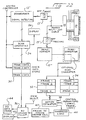
- FIG. 1 is a block diagram of an ultrasonic imaging system 10 which incorporates a presently preferred embodiment of this invention. The following discussion will first present a system overview, and then a detailed description of selected components of the system.
- the system 10 includes a beamformer system/ signal detector 12 which includes both transmit and receive beamformers and is connected via a multiplexer/ demultiplexer 14 to an ultrasonic transducer 16. Any suitable devices, including conventional devices, can readily be adapted for use as the elements 12, 14.
- the ultrasonic transducer 16 will be described in greater detail below in conjunction with Figures 2-4.
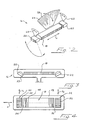
- the transducer 16 preferably includes three separate transducer arrays 18, 20, 22.
- the array 18 is used for collecting image data that will be used to construct displayed representations of the target.
- the arrays 20, 22 are smaller arrays oriented in this embodiment at right angles to the image data array 18 to operate as tracking arrays.
- the tracking arrays 20, 22 are used in this embodiment to estimate the motion between respective image data frames from the image data array to allow the image data frames to be registered properly for reconstruction.
- the beamformer system/signal detector 12 sends excitation signal pulses to the arrays 18, 20 and 22 and supplies summed returning echoes to a signal detector.
- the output of the signal detector is supplied to a scan converter 24.
- the beamformer system/signal detector 12 operates the arrays 18, 20, 22 in the conventional manner as phased arrays by properly timing the excitation signals applied to the arrays 18, 20, 22, and by properly timing and phasing the received signals prior to summing.
- the scan converter 24 controls an output display 26 to display preferably the three images generated by the three arrays 18, 20, 22 along with additional information as described below.
- scan-converted image information from the scan converter 24 is stored in a data storage system 28.
- the data storage system 28 includes three separate storage arrays, each storing data for image frames from a respective one of the arrays 18, 20, 22.
- image information from the image data transducer array 18 is stored as frames of image data in the storage array 30, and image information from the tracking transducer arrays 20, 22 is stored as respective frames of image data in the storage arrays 32, 34, respectively.
- the frames of data in the storage arrays 30, 32, 34 are all time marked, so that they can be associated with one another appropriately. This time marking can take the form of real-time clock information or frame number information, for example.
- the frames of image data in the storage array 30 are applied to a computer 36. It is these frames that are used to form the displayed representation of the target.
- the tracking image frames stored in storage arrays 32 and 34 are not registered to create a displayed reconstruction of the target, but are instead used to determine the relative positions of individual frames of image data from the image data storage array 30.
- the image information from the tracking array data storage arrays 32, 34 is supplied to a motion estimator 38.
- the motion estimator 38 compares sequences of images from the tracking transducer array 20 and the tracking transducer array 22 to estimate a component of motion of the transducer 16 between the respective frames. This estimate of the component of motion is smoothed in logic 40, and then applied to a calculator 42 that calculates a vector value defining the best estimate of the movement between selected frames of the image data stored in the image data storage array 30. This vector is then applied as another input to the computer 36.
- the elements 28 through 42 can be designed to operate in real time, and the motion vectors can be displayed on the output display 26 as discussed in conjunction with Figure 20.
- the image data frames and the frame-to-frame translation vectors can then be transmitted to the specialized computer 36 which can either be combined with or external to the ultrasonic imaging system.
- the computer 36 registers selected frames of image data from the image data storage array 30 with respect to one another by appropriate use of the vectors supplied by the calculator 42. Also any necessary interpolation is done, and the respective frames of image data are stored in proper registration with respect to one another in a three-dimensional data storage device 44.
- the computer 36 when operating in a display mode, can select appropriate information from the three-dimensional data storage device 44 to provide a desired image on the display 46. For example, cross sections can be taken in various planes, including a wide variety of planes that do not correspond to the planes of the image data. Also, surface renderings and segmentation displays can be created if desired.
- the transducer 16 is rotated through a sweep under the direct manual control of an operator, smoothly from side-to-side about a single axis of rotation lying along the azimuthal axis on the face of the image data array 18.
- the method described below can account for imperfections in the sweep. During three-dimensional reconstruction, the quality of the reconstruction degrades gracefully as a result of positional error. Distortion rather than blurriness is the result of imperfect motion detection.
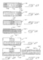
- Figures 2-4 provide three views of the ultrasonic transducer 16.
- the three arrays 18, 20, 22 each comprise a respective set of transducer elements 48, 50, 52, all mounted on a common support element 53.
- the transducer elements 48 are arranged along an azimuthal axis A, and the image data transducer array 18 defines first and second ends 54, 56.
- the tracking arrays 20, 22 are each positioned near a respective one of the ends 54, 56, centered on the azimuthal axis A.
- the transducer elements 50, 52 are arranged along respective tracking axes T1, T2, and the tracking axes T1, T2 are in this preferred embodiment substantially perpendicular to the azimuthal axis A.
- the tracking arrays 20, 22 are each shorter than the image data array 18, and each has fewer transducer elements 50, 52. Each of the transducer elements 48 can be spaced at 1/N times the pitch of the transducer elements 50, 52. As shown in Figure 3, the tracking arrays 20, 22 can be oriented to point inwardly, toward the image data array 18. Alternately, the tracking arrays 20, 22 can be coplanar with the array 18, to provide a preferred profile for the transducer 16.
- the image data array 18 can be of conventional form, such as a flat linear array with a cylindrical elevation focusing lens. Alternately, the array can be generally flat, but the transducer elements can be curved in elevation to focus. In this case a non-refractive filler such as a polyurethane can be used since a focusing lens is no longer required. Whether or not a lens is used, the image data array may be curved in azimuth to yield a larger field of view.
- the tracking arrays 20, 22 will typically include a lens to achieve the desired focus in elevation. Since the curvatures of the various lenses or arrays will be in differing planes, a non-refractive filler section may be formed on the transducer 16 to yield the preferred smooth shape.
- the tracking arrays 20, 22 may also be curved with non-refractive windows formed on top of the desired shape.
- Both the image data array 18 and the tracking arrays 20, 22 may be phased sector, Vector®, linear or curvilinear. All imaging modes including B mode, color Doppler, color Doppler energy and the like are supported.
- a conventional TEE transducer such as the biplane V510B transducer of Acuson can be used in a two-transducer embodiment.
- the transducer geometry shown in Figures 3 and 4 can be used to obtain image planes as shown in Figure 2.
- the image plane 58 of the image data array 18 in this embodiment passes through the azimuthal axis A.
- Image data collected with the image data array 18 is positioned along scan lines 64 in the image plane 58.
- the image planes 60, 62 of the transducer arrays 20, 22, respectively, are oriented transversely to the image plane 58.
- the image planes 58, 60, 62 are the central image planes of the respective arrays, that is the only image plane for a 1 D array and the central plane (i.e. the plane not steered in elevation) for a 1.5D array.
- the tracking arrays 20, 22 may have identical transducer element pitches to that used by the image data array 18. This approach allows the same beamformer delays to be used for all three arrays 18, 20, 22.
- the tracking arrays 20, 22 are adapted to form relatively fewer acoustic lines. This is particularly the case if motion detection is concentrated in the vicinity of the center line of the image planes 60, 62. If only a narrow field of view is required for the tracking arrays 20, 22 then the tracking array pitch may be coarser, for example twice the pitch of the image data array 18.
- the tracking array pitch an integer multiple of the image data array pitch
- the same beamforming delays can be used, but with the appropriate channels disconnected, as shown in Figure 5.
- the element-to-element pitch of the tracking array 20 is twice that of the image data array 18, and consecutive transducer elements 50 of the tracking array 20 are connected to only the even or odd signal lines for the transducer elements 48 of the image data array 18.
- each tracking array 20, 22 may be composed of as few as two transducer elements, although this will limit the maximum resolution that is achievable.
- Common signal conductors can be used between the beamformer/signal detector 12 and the housing for the transducer 16.
- individual signals are routed between the signal conductors and the transducer elements 48, 50, 52 by high voltage analog switches or multiplexers, such as those available from Supertex Inc., Sunnyvale, California and having the family designation HV2xx.
- Figures 6-11 are schematic views that illustrate the manner in which images generated by the tracking arrays 20, 22 can be used to estimate the movement between images generated with the image data array 18.
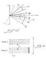
- Figure 6 shows a perspective view for three separate positions of the transducer 16. These three separate positions of the transducer 16 are obtained by rotating the transducer 16 about the azimuthal axis. As the image data array 18 rotates about the azimuthal axis A, the image planes 58A, 58B, 58C rotate in a fan-like manner. Thus, each of the image planes 58A, 588, 58C of Figure 6 is disposed in a separate, respective plane of three-dimensional space.
- the image planes 60A, 60B, 60C; 62A, 62B, 62C for each tracking array 20, 22 remain coplanar as the transducer 16 is rotated about the azimuthal axis A.
- the actually imaged regions within the image planes 60A, 60B, 60C; 62A, 62B, 62C rotate about the azimuthal axis A as the transducer 16 rotates.
- the imaged regions within the image planes 58A, 58B, 58C will not overlap or intersect the imaged regions within the image planes 60A, 60B, 60C or the imaged regions within the image planes 62A, 62B, 62C. This arrangement can reduce cross talk and other interference problems, as discussed below.
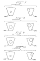
- Figures 7-10 show four sets of images.
- Each set includes an image 66A, B, C, D from the image data array 18 and a corresponding image 68A, B, C, D from one of the tracking arrays 20, 22.
- the target is a sphere
- the images 66, 68 intersect such that the sphere appears in both images 66, 68.
- images 66A, B, C, and D various cross sections of the sphere are displayed as the transducer 16 rotates about the azimuthal axis.
- the cross sections shown in images 66A and 66D show smaller diameter disks taken near an edge of the sphere, and the images 66B and 66C show larger diameter disks taken near the center of the sphere.
- the disks shown on the images 66A, B, C and D differ in diameter, in accordance with the moving plane of the image (see Figure 6).
- the images 68A, B, C, and D all show disks of the same size. Because the plane of the images 66A, B, C, and D remains the same, as discussed above in conjunction with Figure 6, the disk that is displayed in these images remains constant in size but moves across the image plane. The location of the disk as it moves from one image to the next provides a measure of a component of motion of the transducer 16 in the image plane of the images 68A, B, C, D.
- the image plane of the transducer arrays 20, 22 are not perpendicular to the surface of the image data array 18 (for example because the tracking arrays 20, 22 are pointed inwardly as shown in Figure 3), it may be preferred to use a cosine ⁇ correction factor to take account of the difference between image range and physical depth perpendicular to the image data array 18.
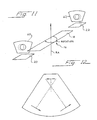
- transducer 16 includes two tracking arrays 20, 22, each positioned near an adjacent end 54, 56 of the image data array 18. This arrangement allows compound rotations to be assessed.
- the transducer 16 is rotated about a rotational axis RA oriented as shown.
- the solid-line circles denote the image of the target at a first point in time
- the dotted-line circles denote the image of the target at a subsequent point in time, after rotation about the rotational axis RA. Note that the images move in opposite directions in the image planes 60, 62 in this situation.
- the transducer 18 can include an absolute sensor for position, orientation, or both, such as a magnetic sensor 19 as shown in Figure 21 or an accelerometer.
- the sensor 19 may be used to supplement or back up the motion detection approach described in detail below, and may be of the types described in Keller U.S. Patent 5,353,354.
- the image data array 18 and the tracking arrays 20, 22 are sequentially operated.
- the transmit beamformer in element 12 sends appropriately timed and phased excitation signals to the respective transducer elements 48, 50, 52.
- a frame of data from the image data array 18 is collected, and then frames of data from the tracking arrays 20. 22 are collected.
- the transmit beamformer may alternate between the image data array 18 and the tracking arrays 20, 22 between individual scan lines or between groups of scan lines.
- the pulse repetition rate (which is normally limited by the time required for ultrasonic signals to attenuate in the body between successive scan lines) may be increased.
- the arrays 18, 20, 22 may be connected in common to the transmit beamformer.
- the imaging requirements for the image data array 18 will differ substantially from those for the tracking arrays 20, 22.
- Image data quality should be maintained at a high level, but tracking data need only be of sufficient quality to permit reliable tracking. Costs may be reduced by sharing some cable conductors between the array 18 and the arrays 20, 22.
- elements near the ends of the image data array 18 are most suitable for sharing, since they are less important than center elements.
- cable routing from the elements 48 of the image data array 18 to the elements 50, 52 of the tracking arrays 20, 22 is preferably jumbled in a known pseudo-random manner.
- the element 12 uses the jumbling scheme to sort the beamformer delays such that one set of arrays (either the image data array 18 or the tracking arrays 20, 22) is operated coherently at any given scan line. The other set is operated incoherently because of the cable jumbling.
- the optimum jumbling scheme may be determined by routine experimentation.
- Cross talk may be further reduced with frequency coding and voltage level techniques.
- the tracking arrays 20, 22 may operate with a reduced image depth, such as a few centimeters, and therefore a high frequency such as 10 MHz.
- the image data array 18 may operate at a longer range, lower frequency such as 5 MHz, thereby reducing cross talk.
- the transducer elements 48, 50, 52 may be formed with thicknesses that select the appropriate frequencies. Also, bandpass filters may be used in the element 12 to select the desired frequency bands for detection.
- Voltage levels may vary between the two sets of arrays 18, 20, 22. For example a higher voltage may be used when the tracking arrays 20, 22 are selected, particularly if the tracking arrays 20, 22 require a higher voltage to operate effectively. In this case the tracking arrays 20, 22 emit a relatively small signal when the image data array 18 is selected and the voltage level is reduced.
- Figure 22 shows an alternative system 10' which uses many of the same components as the system 10.
- the system 10' differs in that the arrays 18, 20, 22 are operated simultaneously at different frequencies by beamformer/signal detectors 12', 12".
- a respective bandpass filter 13', 13" is provided to isolate the bandpass of interest.
- the tracking arrays 20, 22 may operate at 10 MHz and the image data array 18 may operate at 5 MHz.
- the jumbled cable routing discussed above may be used to reduce interference.
- the bandpass filters 13', 13" can operate on beamformed signals, but the arrangement of Figure 22 is preferred in practice.
- the preferred format for the image data array 18 is the sector format.
- Acoustic line data acquired by in the sector format can be conveniently used in the correlation process without scan conversion, since, for example, a pure rotation in rectangular coordinates can be represented as a change in an angular coordinate in a suitably chosen cylindrical coordinate system, given knowledge of the line to line angular increment, the angles of the lines with respect to the normal line (see Figure 15), and the sample to sample range increment.
- Motion detection may be performed manually, for example by placing a line on the display data at a particular recognizable feature in the image planes 60, 62 and then repeating this activity on subsequent frames.
- the system can keep track of the line position for successive frames to generate a vector indicative of frame-to-frame motion.
- a better method is to use computer analysis of frame-to-frame motion using a cross correlation or similar method on the image data acquired with the tracking arrays 20, 22.
- Such techniques (which will be referred to herein generally as correlation techniques) have been used in the past for tracking blood flow. These methods do not require that a recognizable feature be present in the display area, and they can function adequately using only ultrasound speckle data. Speckle is a naturally occurring phenomenon in ultrasound images and is a result of the coherent nature of the reflected waves from small scattering objects in the tissue.
- Any suitable correlation technique can be used, including cross correlation and the sum of absolute differences method as discussed in Bohs and Trahey “A Novel Method For Angle Independent Ultrasonic Imaging Of Blood Flow And Tissue Motion” (IEEE Trans. on Biomed. Eng., 38 , 3, pp. 280-286, March, 1991).
- Cross correlation is the well-known mathematical operation which uses sequentially obtained sums of multiplication operations for various translations of data in a search for the translation for which the two sets of data are best matched.
- the sum of absolute differences method is a computationally simpler correlation technique, but it achieves a similar net effect.
- the sets of data are translated by varying amounts. For each translation respective data values in each of the sets are subtracted and the sum of the absolute differences is calculated.
- This translation required to achieve an alignment is an indication of the motion between the two respective frames at the sides of the image closest to the respective tracking array.
- the motion at other parts of the image can be evaluated using the detected motion at both tracking arrays and linear interpolation techniques along the azimuth of the image data array 18.
- the size of the data block used in either type of correlation is a matter for optimization. Bigger blocks will have a reduced likelihood of a false match but will require longer calculation times.
- the maximum frame-to-frame displacement that can be detected is limited by the block size. Typically, searches are made to plus or minus one-half of a block size. By way of example, a 16 x 16 pixel block may be used to detect a maximum translation of plus or minus 8 pixels.
- the motion estimator 38 can use any effective technique to determine motion based on the frames of data stored in the arrays 30, 32, 34.
- Motion estimation may be based on the entire frame or on portions of the frame. When portions are used, they may be selected to correspond to a well-defined feature in the image. Motion estimation may be used on a spaced subset of available data to save time if that is more efficient. For example, if samples are available on a 0.5 mm spacing, but optimized motion detection can be performed based on a 1 mm spacing, time can be saved by deleting altemate samples and performing motion detection based on only a subset of the available data.
- the tracking image data used for the motion estimation may take any one of a number of forms, including at least the following:
- the beamformer outputs lines of acoustic data may be in polar or cartesian format. Since the relation between these lines of data and the physical lines of propagation are known, samples derived from these acoustic lines may be used in the motion detection.
- Figure 15 is a schematic view showing the position of a target at frames N and N+1 with respect to acoustic scan line data.
- reference symbol 70 is used for individual points at which the measurements were taken. These points are arranged at discrete intervals along the scan lines.
- Figure 16 shows the raw acoustic line data (prior to scan conversion), in which each row represents a respective scan line, and the points of measurement at respective ranges are as illustrated.
- the + symbol is used for the position of the target for both frames N and N+1.
- the motion estimator 38 when operating on frames N and N+1, detects that the target has moved from scan line 1 to scan line 3 and the range has remained constant at four sample intervals from the origin.
- acoustic line data When acoustic line data is used in the motion estimator, it can correspond to digitized RF, digitized IF, digitized baseband, or rectified low-pass-filtered, envelope-detected signals. As an example of envelope-detected signals, B-mode data can be used.
- the acoustic line data signals may be real digital samples or complex (I, Q) data samples.
- the approach used in the motion estimator 38 relies on the sum of absolute differences in a pixel block equal to 16 x 16 pixels.
- the LSI Logic 64720 integrated circuit is designed to perform 16 x 16 motion detection at rates of up to 396 blocks in 1/30th of a second. These circuits may be combined to yield higher throughput or larger block sizes. If the block size is reduced to 8 x 8 pixels, still higher rates are possible (4500 blocks in 1/30th of a second).
- This integrated circuit has the cost benefits of volume manufacture. Similar alternative integrated circuits may also be used. Alternatively, the entire operation can be performed using a suitably programmed general purpose processor such as the Texas Instruments TMS 320C80.
- the arrays 18, 20 are aligned with the array 16 such that the image plane 58 is aligned with the vertical axis of the image planes 60, 62. For this reason, motion with respect to the centerline of the image planes 60, 62 can be used to determine the relative motion of the image plane 58. Data blocks are defined lying along the center line.
- an image of one of the tracking arrays can include an organ 72 having a bulk motion indicated by the arrows 74 which is different from the motion indicated by the speckle of the larger part of the area of the image.
- the bulk motion of the organ can be disregarded, and the average of the remaining estimates of motion indicated by the shorter arrows 76 can be used as an estimate of the motion of the frame.
- One suitable approach is to quantize the motion vectors (length and direction), and then to find the most commonly occurring quantized length and direction. Next the actual (unquantized) vectors within a tolerance band (e.g. ⁇ 30%) of the most commonly occurring values are selected and averaged to generate the desired estimate.
- the ratio of the minimum sum to the average sum (after removing the minimum sum value) can be used as an indicator of the quality of the image motion detection. If the minimum sum is close to the average, then the calculation is susceptible to error, i.e. falsely detected motion.
- the sum of the error values output is an indicator of a low quality result (a high error value sum corresponds to a low quality result).
- Low quality tracking may also be detected by comparing estimates of motion. Adjacent or successive estimates of motion which are not similar to one another may be an indication of low quality motion estimation. Of course, two or more of the approaches described above may be used in combination.
- Speckle patterns change rapidly as motion occurs.
- a speckle pattern will change if the elevation slice position moves. This is because speckle scatterers move in and out of the image plane rather than remaining within the plane and moving parallel to it. For this reason it is preferable in many cases to make frequent motion estimates as the transducer 16 is moved. The exact frequency of the estimates will depend upon the scale of the motion detection problem, which is related to the speed of motion imposed by the operator, the operator's ability to maintain slice position, and the nature of the speckle target (which is a function of tissue type and ultrasound frequency).
- M is a integer greater than 1, such as 10.
- this approach can be used to correct cumulative errors.
- the probability of such a large motion being correctly estimated is less. Therefore, the value of M is a matter for optimization.
- elevation slice affects speckle quality and stability, it may be preferable to track motion at the elevation focus of the lens. Alternately, if the speckle dependence is too sensitive at the elevation focus, it may be preferable to avoid that area. It may be preferable to apply varying weightings to the detected motions during the smoothing operation to maximize the net accuracy by taking more account of more accurate data. It may be preferable to use an elevation focused array (1.5D array) or perhaps an unfocused array if that appears during experimentation to provide the best results.
- 1.5D array elevation focused array
- unfocused array perhaps an unfocused array if that appears during experimentation to provide the best results.
- Envelope-detected, scan converted data is a simple design choice, and is presently preferred.
- Alternatives include envelope-detected data prior to scan conversion and RF or baseband beamformer output signals prior to envelope detection.
- the user can select regions of interest if for some reason the user has specific preferences about which regions in the tracking data image would provide the best motion detection. For example, a user may choose not to use volumes of moving blood as regions for motion detection.
- the preferred display is as shown in Figure 20.
- an image from the image data array 18 is shown centrally on the screen and tracking images from the tracking arrays 20, 22 are shown on respective sides of the screen.
- motion detection is performed in real time, and the detected motion is presented on the display by indicating the calculated motion as it occurs in real time.
- This display can take the form of motion vectors as shown in Figure 20.
- numeric measures of detected motion can be displayed. These displays indicate the relative position of the transducer in the sweep, and therefore provide the operator with an indication as to when the desired angular motion has been completed and also provide an indication of whether the motion detection system is working properly.
- the image data may be displayed without the tracking images or without display of the detected motion.
- the system can prompt the operator to begin again, as for example with an audio prompt such as an alarm or a visual prompt such as a flashing, reverse video message.
- the system 10 can be programmed to assist the user in achieving an optimum sweep rate.
- optimum use of the motion estimators calls for an optimized sweep rate, i.e., a sweep rate that is large enough to avoid unacceptable error accumulation and small enough to remain within the range of movement of the motion estimator. Either an audio or a video prompt may be used.
- the system may emit an intermittent tone when the sweep rate is approximately correct (e.g., 4 pixels of movement per estimate). If the estimated movements are too small (e.g., less than 2 pixels), the intermittent tone is replaced with a low continuous tone, which becomes even lower if the sweep rate slows further. Conversely, if the estimated movements are too large (e.g., greater than 6 pixels), the intermittent tone is replaced with a high continuous tone, which becomes even higher if the sweep rate speeds up.
- the sweep rate is approximately correct (e.g., 4 pixels of movement per estimate). If the estimated movements are too small (e.g., less than 2 pixels), the intermittent tone is replaced with a low continuous tone, which becomes even lower if the sweep rate slows further. Conversely, if the estimated movements are too large (e.g., greater than 6 pixels), the intermittent tone is replaced with a high continuous tone, which becomes even higher if the sweep rate speeds up.
- a suitable visual prompt includes a variable-length arrow, which can have a longer length to prompt a faster sweep rate and a shorter length to prompt a slower sweep rate, and which can flash to indicate an optimum sweep rate.
- Another approach is to program the motion estimator to select the spacing in time of the frames that are correlated to estimate the component of motion.
- this spacing By properly selecting this spacing in an adaptive manner, the measured component of motion can be kept within the optimum range for a wide range of sweep velocities. For example, if there are many non-used tracking frames between each pair of correlated tracking frames, and if 8 pixels is the maximum detectable motion, the number of non-used tracking frames between each pair of correlated tracking frames can be increased or decreased as necessary in real time to maintain the detected motion in the range of 4 to 6 pixels.
- Low quality motion estimates can be weighted at a low level or entirely removed.
- One approach for selecting low quality motion estimates is first to fit a curve to all of the motion estimates (both in length and angle). Then the individual motion estimates are compared to the fitted curve, and motion estimates that deviate from the curve by more than a threshold amount such as 30% are considered low quality motion estimates and are deleted from the collection of motion estimates. Then the curve fitting operation is repeated using only the remaining motion estimates. If more than a certain fraction such as 20% of the motion estimates are classified as low quality estimates, the operation can be abandoned and the user prompted to repeat the sweep.
- the tracking arrays are on either side of the image data plane, and the exact geometry of the image data plane with respect to the tracking arrays is known, it is possible to interpolate linearly along the image data array azimuth axis to calculate the exact pixel translations for all points on the image data plane.
- motion estimates are collected along a straight line or across a rectangular grid. Due to the constraints of the array geometry and the propagation of the straight acoustic lines from the array, the theoretical behavior of the motion vectors as a function of depth must satisfy certain constraints. In particular, the lengths of the motion vectors should vary linearly with depth. These constraints can be used to reduce the error in the estimated motion. For example, a sequence of motion estimates can be acquired as a function of depth and then converted to motion estimate vectors (length and angle). A straight line is then fitted using well known methods to determine the best fitting line to the actual data for the length component. A second straight line is then fitted to the actual data for the angle or direction component. These fitted lines (comprising length and direction) can be linearly interpolated along the azimuthal direction during three-dimensional reconstruction at intermediate locations other than those used to derive the motion vectors.
- ECG gating and breathing gating are well known in three-dimensional reconstruction of images. See, for example, McCann et al. "Multidimensional Ultrasonic Imaging for Cardiology" at p. 1065. With ECG gating a window is selected a fixed time duration after the ECG pulse maximum. With breathing gating it is often simplest to ask the patient to hold his or her breath for the short duration of the ultrasonic scan. Alternatively, chest motion can be recorded using a displacement sensor, and data can be selected for a portion of the breathing cycle.
- Various other techniques can be used to optimize motion estimation. For example, accuracy can be improved by interpolating to finer and finer pixels. Noise in the data can be removed using a low pass filter or a median filter, and the mapping of voltage level to brightness can be optimized for motion estimation purposes.
- logarithmic compression is used on the tracking arrays 20, 22, and this logarithmic compression can be optimized independently of the logarithmic compression used for the image data from the image data array 18.
- the particular mapping that is used can vary widely according to the operator's wishes. It is likely that in many cases motion detection will function most efficiently using a different mapping than that used by the operator for the image data. If desired, the system 10 can vary the mapping used intemally for the data from the tracking arrays 20,22 until a mapping is found that provides high quality motion detection.
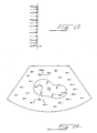
- FIG. 17-19 One example is shown schematically in Figures 17-19.
- the image data frames prior to reconstruction are shown schematically in Figure 17.
- the image data frame for the central plane is inserted at a plane aligned with the center of the volume, as shown in Figure 18.
- Working outwardly from this center plane successive image data frames are inserted into their appropriate XYZ locations, as shown in Figure 19.
- intermediate points are calculated using three-dimensional linear interpolation techniques relying on the eight closest known data points, arranged as a cuboid around the point to be interpolated.
- Such three-dimensional manipulation techniques are known, and are therefore not described in detail here.
- One approach is to use the scan conversion interpolation method described by Leavitt in Hewlett Packard Journal, October, 1983, pp. 30-34, adapted for use in three dimensions.
- the approach described by Leavitt operates with data in a two-dimensional plane. Data in three dimensions can be treated in two successive two-dimensional operations. Image plane data can be scan converted and interpolated as described by Leavitt, using pixel spacings that match the requirements of the three-dimension scan conversion. Then an orthogonal two-dimensional scan conversion can be performed at each azimuthal position to fill out the volume in the perpendicular direction.
- the Leavitt technique assumes that the axis of rotation for successive two-dimensional images is correctly aligned. If this is not the case, other volumetric reconstruction methods can be used. Suitable reconstruction methods are well-known and are used with conventional magnetic sensor-based systems.
- frames 1, 3 and 5 can be approximately assumed to be the correct frames lying at approximately 0, 2, and 4 degrees. The error from the approximation is insignificant and may result in simplicity in the reconstruction.
- a component of motion within the image data frame can also be detected using the techniques discussed above. This component of motion will be parallel to the azimuthal axis, and can be added to the motion detected with the tracking arrays, which is perpendicular to the azimuthal axis. Since the image data from the image data array 18 will move significantly due to motion of the elevation plane, it is preferred that motion detection be over-sampled in this plane. Preferably, only a measured net motion is applied during the reconstruction, as discussed above in conjunction with Figure 14.
- motion can be detected in the plane of the image data frame when the transducer 18 is moved in translation along the azimuthal axis, as opposed to the rotational sweeps discussed above.
- an extended field of view can be provided by axially shifting the transducer 16 along the azimuthal axis, without rotating the transducer 16. If the only interest is in tracking such linear translation, the tracking arrays 20, 22 are not required.
- extended field of view denotes a system which stores image data from a transducer array as the transducer array is shifted axially along its azimuthal axis. Data from the array at various positions along the azimuthal axis are then registered for reconstruction to form an extended field of view image.
- the extended field of view discussed above can be reconstructed with data from either one of the tracking arrays 20, 22 or the image data array 18. More logically, the image data array 18 is used, because the image data array 18 is optimized for image quality. The image data array is then translated with respect to the target tissue, with its azimuthal axis oriented parallel to the line of motion. Image motion detection using the techniques described above is performed on image data from the image data array 18. Successive frames of image data from the array 18 are stored, along with displacement information defining the motion between frames of image data.
- the displacement information is used, starting with the most recently acquired image data frame, to register successive ones of the image data frames with respect to one another in proper alignment, in the tissue sense.
- the older image data is then superimposed on the newer image data.
- most of the older data will almost exactly match the newer data, but a small non-overlapping region will be present which represents data acquired at the older image position which could not be acquired at the newer image position.
- Scaling may be achieved by remapping the pixels to a new memory using geometric transformation and interpolation, as is well known in the computer graphics field.
- the image data frames that are optimized for motion detection need not be displayed on the screen. Instead, only the image data frames that are optimized for imaging can be used.
- frames 1 and 11 can be image data collected using user- determined center frequency and bandwidths.
- Frames 3 and 13 can be motion detection frames with first alternative center frequency and bandwidth.
- Frames 5 and 15 can be motion detection frames with second alternative center frequency and bandwidth, and frames 7 and 17 can be motion detection frames with the first alternative center frequency and the second alternative bandwidth.
- Frames 9 and 19 can be motion detection frames using a changed focusing scheme.
- Frames 2, 4, 6, 8, 10, 12, 14, 16, 18 and 20 are captured as if they were image frames and are displayed, but are not stored or used for tracking.
- the detected motion from frames 1, 3, 5, 7 and 9 with respect to frames 11, 13, 15, 17 and 19, respectively, may then be averaged or sorted so as to eliminate motion estimates which are significantly different from other estimates.
- the actual motion may be calculated approximately from the sum of the tracking array motions and the image data array motions, separately measured. If after the sum of such motions is obtained it is found that the second motion to be applied has caused the first motion to have been modified, a recursive operation can be employed until a three-dimensional motion is found which correctly satisfies the detected motions in all arrays.
- a Monte-Carlo method for finding the components satisfying a complex motion may be used. Additionally, new motions may be estimated from the last frame-to-frame motion which was calculated.
- the system can find that it is unable to determine a set of motion component vectors which satisfy the detected motions and can signal the operator to repeat the last sweep.
- a simpler device for implementing the bi-plane imaging techniques discussed above can be constructed as follows.
- This device also uses a linear array for the image data acquisition and two small linear arrays of equal pitch that are mounted to move with the larger linear array.
- the two small linear tracking arrays are coupled to a connector similar to that used by the image data array, but the transducer elements are divided so that the transducer elements for each tracking array are coupled to the transducer connector near the opposite ends of the connector. For example, for a 128 conductor connector and a 10 element tracking array, the conductors 10-19 and 100-109 can be used for the two tracking arrays.
- Both the image data array and the combined tracking array are provided with a connector of the same type and are designed to operate with the same beamformer.
- the two connectors are inserted into the left and right ports of a suitable ultrasonic imaging machine, such as the Acuson Model XP, and an image storage device such as a VCR is provided.
- a suitable ultrasonic imaging machine such as the Acuson Model XP
- an image storage device such as a VCR is provided.
- the array is rotated slowly the operator presses the array select switch (left versus right) repeatedly at a high rate and the resulting images are stored for off-line analysis.
- the VCR tape is played back on a frame-by-frame basis.
- Successive sets of frames, each set consisting of a frame from the image data plane and each tracking image plane are transferred via standard video transfer techniques to a computer memory.
- the computer is programmed to analyze the tracking image plane data for motion detection using the methods discussed above.
- the tracking image will in fact appear as two images, one on each side corresponding to the two spatially separated tracking arrays.
- the two images are analyzed separately.
- the ultrasonic imaging machine is preferably programmed to perform the array switching operation and to transfer one set of frames from each sequential sweep to computer memory or to a suitable storage device.
- crossed arrays of the type described in Hashimoto U.S. Patent 5,327,895 and Schaulov, et al., Ultrasonics Symposium, pp. 635-638 (IEEE, 1988) can be adapted for use with this invention.
- Such crossed arrays typically include a PZT plate which is diced in perpendicular directions.
- the kerfs are filled with a low-durometer polymer such as a low-durometer epoxy.
- Linear electrodes (defining the array elements) are applied to the top and bottom surfaces, and the electrodes on the top surface are oriented perpendicularly to the electrodes on the bottom surface.
- all electrodes on the top surface are grounded and the electrodes on the bottom surface are excited with the phased excitation pulses.
- the electrodes on the bottom surface are then monitored for detected echoes.
- the bottom surface electrodes are grounded and the top surface electrodes are operated in a phased manner.
- Figures 23-26 show schematic views of four crossed arrays that can be used to collect both image data and tracking information.
- the elements 102 form a conventional one-dimensional array that can be used to collect image data.
- Crossed elements 104 at both ends of the transducer 100 can be operated as tracking arrays as described above.
- the transducer 100' is similar to the transducer 100 except that the crossed elements 104' are provided only at one end.
- the crossed array 100" of Figure 25 is also similar to the array 100 of Figure 23, except that the crossed elements 104" are provided only at the center of the transducer.
- Figure 26 shows a transducer 100''' which is similar to the transducer 100" of Figure 25, except that the crossed elements 104''' extend over the entire length of the array.
- one or more tracking arrays can be integrated with an image data array using the crossed array technique.
- the crossed array is operated in the normal manner along the long, azimuthal axis to obtain 2-D image data.
- the crossed arrays are operated to obtain data along the elevation direction to obtain the perpendicular tracking data. In this way the footprint of the transducer is minimized.
- the tracking data may be acquired from the same volume of tissue as that being interrogated to obtain the image data.
- FIG 27 provides a schematic view of another transducer 110 which includes an image data array 112 and a single tracking array 114.
- the tracking array 114 is oriented perpendicularly to the image data array 112.
- the tracking array 114 is laterally offset from and centered with respect to the image data array 112.
- FIGs 27a through 27e show five alternative transducers, each including a single image data array 112 and at least one tracking array 114.
- the transducer of Figure 27a there are two tracking arrays 114, both laterally offset from and centered with respect to the image data array 112.
- the transducer of Figure 27b there is a single tracking array 114 that is co-linear with and axially spaced from the image data array 112.
- the transducer of Figure 27c includes two tracking arrays 114, both positioned to the same side of the image data array 112 near opposite ends of the image data array 112.
- the transducer of Figure 27d is similar to that of Figure 27c, except that the two tracking arrays 114 are positioned on opposite sides of the image data array 112.
- the transducer of Figure 27e includes four tracking arrays 114, two on each side of the image data array 112, near respective ends of the image data array 112.
- Transducer geometries that place the tracking arrays alongside the image data array may reduce the overall length of the transducer, which may provide advantages in some applications.
- a transducer 120, 120' suitable for use in forming an extended field of view as described above can utilize an image data array 122 and a tracking array 124, wherein the transducer elements of the two arrays 122, 124 are parallel to one another.
- the tracking array 124 is laterally offset from and centered with respect to the image data array 122.
- the image data array 122' and the tracking array 124' are collinear and separated from one another. With either of the transducers 120, 120' frame-to-frame motion can be determined using the tracking arrays 124, 124' and the compound image can be assembled from image data from the image data array 122, 122'.
- some or all of the tracking arrays and the image data arrays may be formed as non-planar linear arrays such as curved linear arrays for example. Separate, oriented linear arrays may be used for each acoustic line if desired.
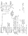
- FIG 30 is a block diagram of an alternative ultrasonic imaging system 10' that is in many ways similar to the system 10 of Figure 1.
- the same reference numerals have been used for comparable elements in the two drawings, and the following discussion will focus on the differences.
- the system 10' stores image data from the image data array 18 or one of the tracking arrays 20, 22 in a raw image data buffer 15.
- the data stored in the buffer 15 can be I, Q data or IF data, for example.
- image information is intended to refer broadly to information that varies with spatial variations in the target, and in many cases image information is never displayed as an image.
- the raw image .data stored in the buffer 15 includes tracking data stored with wide band ultrasound pulse operation.
- Image data from the buffer 15 is passed to a detector 21 through one of four alternative blocks.
- Block 17 is an all-pass block which performs no filtering, and which is typically used for image data from the image data array 18.
- Tracking data from one of the tracking arrays 20, 22 can be passed through one of three filters 19, 19', 19", which can have varying filter characteristics.
- filter 19 may be a low-pass filter and filter 19' may be a high-pass filter.
- Filter 19" may be a band-pass filter centered in any desired portion of the frequency spectrum.
- the detector 21 can be any conventional detector, and it supplies a detected output signal to the scan converter 24. If desired, tracking data from the tracking arrays 20, 22 can be processed multiple times, using different ones of the filters 19, 19', 19". Of course, more or fewer filters can be used in alternative embodiments.
- the scan converter 24 preferably uses the well-known histogram equalization method to maximize contrast in the tracking image data. Histogram equalization is discussed for example in Gonzales and Woods, Digital Image Processing , Addison-Wesley, 1993, pp. 173-178, as well as in Kim U.S. Patent 5,492,125.
- the scan converter 24 may use a 2D low-pass filter and/or a 2D high-pass filter to smooth or otherwise process the tracking image data.
- Image frames from the scan converter 24 are stored in the frame buffers 30, 32, 34, and tracking sets of image data from the buffers 32, 34 are selectively applied to the motion estimator 38.
- the motion estimator 38 estimates the relative motion between selected tracking image sets and applies these estimates of motion to a motion smoothing/summing block 40'.
- the motion smoothing/summing block 40' processes motion estimates from multiple motion detection operations.
- each motion detection estimate is associated with a quality factor indicative of the confidence level associated with the motion estimate.
- a suitable quality factor may be value of the minimum sum of absolute differences associated with a particular motion estimate.
- a high value of Q is associated with a high confidence level.
- the previous motion store 41 Figure 3 is used to store previous motion estimates until they are needed in forming the weighted sum described above. Other methods for using multiple motion estimates are described below.
- the acquisition of image data via the array 18 can be time multiplexed with the acquisition of tracking data via the tracking arrays 20, 22.
- the time separation between consecutive tracking data frames is controlled adaptively to provide motion estimates that fall within a desired range.
- the motion estimate i.e. displacement
- the motion estimate between consecutive tracking frames is too low, excessive computational time may be used in creating motion estimates.
- the motion estimates are small, the relative errors will be large, and compound errors may reach undesirable proportions.
- a controller can be provided as described above to determine the number of image data frames that are collected between consecutive tracking frames, and this can be accomplished in an adaptive manner as shown in Figure 31.
- N is used to specify the number of image data frames that are collected between consecutive tracking frames.
- N is initially set to a constant K1, and the controller then waits for a new motion estimate from the motion estimator 38 of Figure 3. If this motion estimate is above a desired range, than N is reduced by the amount ⁇ . Conversely, if the motion estimate is below the desired range than N is increased by ⁇ . Once N has been revised if necessary, the controller then waits for a new motion estimate from the motion estimator 38. In this way the motion estimate is maintained within a desired range automatically, and problems associated with excessively large motion estimates or excessively small motion estimates are avoided.
- the system 10' of Figure 30 is well-suited for use in situations where a remote computer is used to perform motion estimation, either in real time or after a delay.
- remote may mean that the motion estimating computer is connected via a cable or other data link.
- image data frames from the buffer 30 can be compressed using any suitable compression technique such as JPEG prior to transfer to the potentially remote site. After the image data has been received at the potentially remote site, it is decompressed as shown in block 35. Similar compression and decompression blocks can be interposed between the buffers 32, 34 and the motion estimator 38.
- remote motion estimation and 3D volume reconstruction can be performed on a remote workstation such as the AEGIS workstation of Acuson Corporation, the assignee of the present invention.
- the motion estimator 32 of Figure 30 preferably is controlled using the algorithm of Figure 32.
- N defines the frame number of the image region used as a reference in estimating motion
- the symbol N+i is used to designate the frame number of the image region that is to be compared with the reference image region.
- the older frame portion is preferably kept as the reference for motion detection at the top of the frame, while the bottom of the frame is updated once motion is detected in that region.
- the tracking arrays 20, 22 are principally swept along the surface, the majority of motion will be in the elevation direction rather than the depth direction.
- the search region rectangular rather than square. For example, instead of searching an area 64 x 64 pixels, a 128 x 32 pixel area can be searched in the same time (128 lateral search pixels and 32 depth search pixels). Similarly, if the maximum motion is 64 pixels, then by limiting the area of the search to 32 x 64 pixels, the search time is greatly reduced.
- frame motion can be interpolated to further reduce processing time. For example, if tracking frames 1, 3 and 5 are used for motion detection (rather than 1, 2, 3, 4 and 5), then detected motion between frames 1 and 3 can be interpolated to determine the motion for frame 2. In this case the interpolated motion for frame 2 would be one-half of the detected motion between frames 1 and 3.
- This method allows reduced processing time to be spent for motion detection, but allows all acquired image data to be employed in the highest quality 3D image. Interpolation of this type may be performed in the 3D volume translation/interpolation block 36 of Figure 30.
- Various alternative approaches can be used in the motion estimator 38 to further reduce processing time. For example, if a small set of acoustic lines are transmitted, received and stored as one-dimensional RF or baseband signals, then vector components of motion along each of these lines can be estimated by correlating successive sample sequences along the lines. In this way the vector component of motion in each of the line directions can be determined, and these vector components of motion can be summed to create the final two-dimensional motion estimate. If desired more than two acoustic lines may be used in the set, but the following example uses two perpendicular acoustic lines.
- the tracking array 20 can be used to store two acoustic receive lines 140, 142 which are perpendicular to each other. These lines can be considered to make up a single frame of tracking data.
- the line 140 can be cross-correlated between two separate frames of tracking data to find the vector component of motion along the direction of the arrow 144, and similarly the lines 142 in these two frames of tracking data can be used to determine the vector component of motion in the direction of the arrow 146. These two components of motion can then be summed as vectors to estimate the two dimensional motion between the two frames of tracking data.
- Cross-correlation techniques suitable for adaptation to the current task are described in Engeler U.S. Patent 4,937,775, O'Donnell U.S. Patent 4,989,143 and Wright, et al . U.S. Patent 6,570,691. The Wright, et al . patent is assigned to the assignee of the present invention.
- a register is used to store the complex sampled beam data from one firing in one of the two directions.
- the resulting sampled beam data is cross-correlated with the data in the register. From the position of the cross-correlation peak, the relative time delay between the two signals is determined.
- the cross-correlation process may operate on one or more portions of the available line data. By detecting motion via cross-correlation at a number of points along each line, separate motions can be determined at the top and bottom of the image, and hence rotations as well as translations can be estimated.
- the component of transducer motion (parallel to the beam axis) required to cause the measured time delay is inferred from the known speed of sound in tissue and taking account of the fact that the delay is related to two-way path length. This process is repeated for the other line (preferably oriented perpendicularly to the first line) to find the other vector component of motion. These two vector components are then summed to find the estimated actual transducer motion at that point along the array. Similarly, the process is typically repeated at the second side of the array for the second tracking array.
- the two lines are oriented at ⁇ 45 degrees, and there is therefore a strict requirement on element spacing if grating lobes are to be avoided.
- the two lines are oriented at ⁇ 60 degrees to enhance the accuracy of motion detection along the skin of a patient.
- the transducer elements should be spaced at one-half wavelength or less. This requirement may encourage the use of a lower frequency for the tracking arrays than for the image data array.
- the cross-correlation technique will be able to track delay to a small fraction of a wavelength.
- the comparison between one set of tracking data and the next may not be made on every acquired set of tracking data, but rather on a time-spaced subset. For example, if motion is fast, motion estimates can be made between every consecutive pair of sets of tracking data, but if motion is slow a longer time between motion estimates is allowed.
- the finest level of motion detection may be enhanced by interpolating additional pixels between the available pixels.
- the final estimate of transducer motion is preferably based on a composite of multiple inputs.
- these inputs are weighted so that those that appear to possess the greatest quality (or certainty) are given the most weight.
- Inputs which are contradictory with the majority of inputs are either eliminated from the composite calculation or are given very small weightings.
- min_SAD minimum sum of absolute differences
- mean_SAD mean sum of absolute differences
- Weighting_MSAD ( 1 - ( min_SAD / mean_SAD ) ) / ( 1 - min_observable_SAD ) .
- a second quality factor is based on the similarity of the present motion estimate to the previous estimate. This approach is based on the observation that during a smooth scan typical of that which would be used in practice, the actual relative motion between one set of tracking data and a subsequent set of tracking data is similar. If a motion estimate predicts a reversal in motion, then it is probable that it is a bad estimate. Causes for bad estimates may include a noisy image, poor pixel contrast, or the presence of large amounts of flowing blood. Notice that the previous motion estimate that is used as a reference may be either the raw estimate of motion from the MSAD operation or the previous smoothed and weighted estimate. Preferably, the smoothed previous motion estimate is used as the reference to which the most recent raw motion estimate is compared.
- the initial motion-related weighting must be given an arbitrary value such as 0.5.
- the motions are fitted using a weighted least squares method wherein the weightings are those described above for each of the range points for which a motion estimate is available. This process is repeated for both Y direction motion and Z direction motion.
- Z_motion m Z + c ( different m and c ) .
- m_ mod fact ⁇ ( mean ( Weighting_comp ) ) ⁇ m + ( 1 ⁇ fact ⁇ ( mean ( Weighting_comp ) ) ⁇ m_last )
- c_ mod fact ⁇ ( mean ( Weighting_comp ) ) ⁇ c + ( 1 ⁇ fact ⁇ ( mean ( Weighting_comp ) ) ⁇ c_last )
- the final Weighting_comp may be determined using fuzzy logic.
- a fuzzy logic control block takes as inputs Weighting_MSAD and Weighting_seq and combines them to form an output which is Weighting_comp.
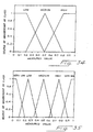
- Inputs Weighting_MSAD and Weighting_seq are first assigned to classes (separate classes for Weighting_MSAD and Weighting_seq). These classes are 'low', 'medium' and 'high'. Membership is based on whether the input comes within each of three triangular-like regions as shown in Figure 34. The derivation of positions of the lines defining in which classes particular measured values will reside is based on experimentation.
- the illustrated regions of the drawings are shown as triangular in shape, it should be noted that the regions may be shaped to follow any continuous function that is determined experimentally to give good results.
- the horizontal axis of the class function corresponds to the input value (Weighting_MSAD or Weighting_seq) and the vertical axis defines the degree of membership of the class.
- Weighting_MSAD Weighting_MSAD
- Weighting_seq Weighting_seq
- a similar class of membership diagram is derived for the fuzzy output Weighting_comp, as shown in Figure 35. In this case the diagram has five regions - very low, low, medium, high and very high.
- Weighting_comp The following fuzzy rules can be applied to determine Weighting_comp; in these rules a logical AND is assumed between Weighting_MSAD and Weighting_seq: Rule No. Weighting_MSAD Weighting_seq Weighting_comp 1 low low very low 2 low medium low 3 low high medium 4 medium low very low 5 medium medium medium 6 medium high high 7 high low low 8 high medium high 9 high high very high
- Fuzzy rules are applied to determine the truth of the rules. For example, assume that Weighting_MSAD and Weighting_seq are 0.35 and 0.9 respectively.
- the 0.35 input results in 0.5 degree of class membership in 'Low' and 0.5 degree of class membership in 'Medium'.
- the 0.9 input results in 1.0 degree of class membership in 'High'.
- the low value of Weighting_MSAD is combined with a logical AND with the high value of Weighting_seq and the minimum value of the two expressions is taken as the truth level of Rule 3.
- the 0.5 degree of membership of 'low' for Weighting_MSAD is less than the 1.0 degree of membership of class 'high' for Weighting_seq.
- the truth level of the Rule 3 is 0.5.
- the medium value of Weighting_MSAD is combined with a logical AND with the high value of Weighting_seq and the minimum value of the two expressions is taken as the truth level of Rule 6.
- the 0.5 degree of membership of 'medium' for Weighting_MSAD is less than the 1.0 degree of membership of class 'high' for Weighting_seq.
- the truth level of the Rule 6 is 0.5.
- a numerical output for Weighting_comp is derived using a centroid defuzzification technique. An estimate of the center of gravity of the entire shaded region in Figure 37 is made. In this case, the center of gravity is at 0.625, and hence the output Weighting_comp is assigned this value.
- Weighting_comp one can use the method shown above to determine the weighted least squares fit and to determine to what extent the current motion should be based on the current motion estimate or on the previous motion estimate.
- the detected motions in the X, Y and/or Z directions are local motions, i.e. motions with respect to the current position and orientation of the transducer and its arrays.
- local motions i.e. motions with respect to the current position and orientation of the transducer and its arrays.
- the local X, Y and Z directions correspond to an assumed global axis system which remains constant throughout the motion of the transducer. If the transducer is rotated about the azimuthal axis of the image plane, as it might during a fan-like sweep, then the local Z motion (depth direction of the transducer) will rotate until it contains a significant component in the global Y or elevation direction.
- the new position and orientation of the transducer in the global axis system are calculated.
- the orientations of the local X, Y and Z directions (i.e. azimuth, elevation, and range or depth of the transducer) with respect to the global axis system are updated. Therefore, subsequent analysis of motion in the local Z direction of the transducer is decomposed into components in the global Z and Y directions, for example.
- the depth or Z direction of the transducer has been rotated from initially pointing down in alignment with the global Z direction to being angled at 45° with respect to the global Z direction.
- a motion in the local Z direction of the transducer of ten pixels is now decomposed into 10cos (45°) in the global Z direction plus 10cos (45°) in the global Y direction.
- the local Z direction is still orientated perpendicularly with respect to the global X direction, and hence a local Z motion has no component in the global X direction.
- the relation of the local axis directions with respect to the global axis directions can be calculated using cosines, which are continuously updated as the transducer is swept through the volume.
- these direction cosines are maintained continuously for all three axes.
- component of motion is intended broadly to encompass translational components, rotational components, and combinations thereof.
- a smooth interpolation scheme is preferably used at the boundaries of the data from different image data frames.
- variable weighting factors can be used to provide such smooth interpolation schemes.
- the right-hand edge of the previous frame ends with pixel number 3 and the new portion of the frame begins with pixel number 4.
- the weighting factor used for the previous frame 1 varies from one within the old frame at pixels 0 and 1, smoothly down to 0 within the new portion of the frame at pixels 5, 6 and 7.
- the weighting factor for the subsequent frame 2 varies from 0 within the old frame at pixels 0 and 1 gradually up to 1 for pixels 5, 6 and 7 of the new portion of the frame.
- compounding can be used for accumulated image data in any of the embodiments described above to reduce noise in the image.
- compounded data may be used with tracking data to reduce noise.
- Y a + bX +cZ for three points to find a, b, c using for example matrix inversion techniques. This step is repeated for a different set of three of the four key points. If the ratios a1/a2 (where a1 and a2 are the 'a' values derived from different sets of three points), b1/b2, or c1/c2 exceed a threshold (either too large or too small), the system can be programmed to warn the user via a video output that the plane is skewed, and that a rescan is appropriate.
- the sum of squared errors in either or both the line and plane case, may be used as a measure of low quality motion estimates and used either internally to adapt the motion estimate (i.e. use larger block sizes or make more motion estimates) or supplied to the user as a video or audible warning, as for example prompting a re-scan.
- the cumulative motion error (which may be derived from the sum of squared errors but is not necessarily exactly equal to the sum of squared errors) may be displayed for the user.
- multiple 2D slices can be reconstructed into a solid 3D volume set.
- a simpler display may comprise a displayed reference bounding box which is 3D in form although displayed as a 2D projection.
- the position and angular orientation of all of the planes of image data are calculated as before.
- a selected 2D slice is displayed oriented within the 3D bounding box displayed on the screen. This can be done using the process described in Keller, U.S. Patent No. 5,353,354.
- the embodiments described above use image data frames to collect data for display and tracking frames to collect data to determine relative motion of the transducers. Since the apertures for the image data frames and the tracking frames are physically separated, the collection of these frames of image data really form two independent beamformer tasks. If desired, multiple simultaneous transmit and/or receive beams can be used to reduce the time required to accumulate tracking data.
- a multiple transmit-beam system which could readily be adapted for simultaneously transmitting ultrasonic beams for the image data frames and the tracking frames is disclosed in US-A-5,675,554.
- a multiple receive-beam beamformer can be used to provide a separate receive beam for each transmit beam, thereby speeding data acquisition.
- the multiple receive-beam beamformer disclosed in US-A-5,685,308 can be adapted for this purpose. See also the multiple receive-beam beamformer disclosed in O'Donnell U.S. Patent 4,886,069.
- the coherent image formation techniques disclosed in US-A-5,623,928 and US-A-5,667,373 can be used advantageously with selected embodiments of this invention.
- the system of the Wright patent applications provides phase alignment between adjacent scan lines in the near field, and, therefore, provides a shift-invariant speckle pattern.
- Such a shift-invariant speckle pattern should provide superior image motion detection based on the speckle tracking than that attainable with a conventional system in which the speckle pattern is shift variant due to a lack of phase alignment between scan lines.
- the system controller includes programmed logic that responds to this condition by alerting the system operator with a warning message, such as an audible tone or a visual message on a display screen.
- a warning message such as an audible tone or a visual message on a display screen.
- the systems and methods described above provide a number of important advantages. They are insensitive to the electromagnetic environment and to patient motion, in contrast to magnetic orientation methods.
- the present invention is potentially implemented at lower cost than magnetic methods, and lower specification transducer arrays can be used. Potentially, the techniques described above can provide excellent accuracy of registration, since accuracy is determined by imaging resolution which scales with frequency.
- the improved transducers described above may require more or larger cables, and the footprint of the transducer may be slightly extended. However, these potential problems may be minimized by using the techniques described above.
Description
- This invention relates to an improved system, method and transducer for acquiring two-dimensional image information and relative positional information regarding the image information to allow subsequent three-dimensional or extended field of view reconstruction.
- There is growing interest in three-dimensional ultrasonic images. One approach is to use a two-dimensional transducer array to obtain three-dimensional image information directly. A two-dimensional array can be used to scan electronically in any desired orientation, and thereby to acquire the desired information. This approach brings with it considerable problems related to fabrication difficulties, signal to noise difficulties and processing difficulties.
- Another approach is to collect multiple two-dimensional image data frames using a one-dimensional transducer array along with relative positional information among the image data frames so that these frames may be subsequently assembled in a three-dimensional volume to form the desired three-dimensional reconstruction. One approach is to use a motorized array to collect the desired set of image data frames by precisely controlling the movement of the transducer array. One example is the transducer shown in U.S . 5, 562,096. See also Pini U.S.
- Patent No. 5,159,931). A related approach is to use a large rotating transducer as described in McCann et al., "Multidimensional Ultrasonic Imaging for Cardiology" (Proceedings of IEEE, 76, 9, pp. 1063-1072, Sept. 1988). Another approach is to use manual motion detection techniques based on analysis of ultrasonic images. See Sapoznikov et al., "Left Ventricular Shape, Wall Thickness and Function Based on Three-Dimensional Reconstruction Echocardiography" ("Computers in Cardiology," IEEE Computer Society Press, Cat CH 2476-0, pp. 495-498, 1987): and Taruma et al., "Three-Dirnensional Reconstruction of Echocardiograms Based on Orthogonal Sections" (Pattern Recognition, 18, 2, pp. 115-124, 1985). Manual techniques are slow and cumbersome and, therefore have many drawbacks.
- Schwartz U.S. Patent 5,474,073 describes a qualitative three-dimensional method using a hand-held transducer array and an assumed scan motion. Qualitative methods have drawbacks, and the present invention is directed to a quantitative method.
- Keller U.S. Patent 5,353,354 discloses a transducer array equipped with accelerometers or magnetic sensors designed to measure the orientation of the transducer, and therefore relative motion between respective image planes. Once the image plane positional information is provided, standard methods are employed for assembling the image plane information into a three-dimensional volume and providing an appropriate display such as a cross section, a surface rendering, a segmentation, or the like. One drawback of the Keller approach is that it relies on assessing the position of the transducer array with respect to a fixed surface exterior to the patient, not with respect to the patient or other target. If the patient moves, the absolute position of all target regions is moved, and the accuracy of the three-dimensional reconstruction is degraded or eliminated entirely. Magnetic sensor systems have additional disadvantages, such as potential vulnerabirity to local magnetic interference from metal objects and electromagnetic fields generated by electronic devices such as cathode ray tubes. Accelerometer systems can be bulky and susceptible to cumulative error, since they rely on two stages of integration to convert acceleration information to displacement information.
- The present invention is directed to a new system and transducer which to a large extent overcome the problems discussed above.
- According to the present invention, there is provided an ultrasonic transducer as defined in
claim 1. - This arrangement for an ultrasonic transducer allows both tracking information and image information to be collected concurrently. The tracking information is used to determine estimates of the movement of the transducer and/or the target between respective image data frames. This information can then be used in registering the respective image data frames appropriately in three-dimensions to form the desired three-dimensional representation.
- Further aspects and advantages of the invention are discussed below in conjunction with the preferred embodiments.
-
- Figure 1 is a block diagram of an ultrasonic imaging system that incorporates a presently preferred embodiment of this invention.
- Figure 2 is a schematic perspective view of the transducer of Figure 1.
- Figure 3 is a schematic side view of the transducer of Figure 2.
- Figure 4 is a schematic plan view of the transducer of Figure 2.
- Figure 5 is a schematic view of a portion of the system of Figure 1.
- Figure 6 is a schematic perspective view showing the movement of image regions as the transducer of Figure 2 is rotated about the azimuthal axis.
- Figures 7, 8, 9 and 10 are schematic views showing images acquired with the transducer of Figure 6 at four rotational positions of the transducer.
- Figure 11 is a schematic perspective view showing the operation of the transducer of Figure 2.
- Figure 12 is a schematic plan view of a tracking image region generated with the system of Figure 1.
- Figure 13 is a schematic view showing the averaging of estimates of motion in the system of Figure 1.
- Figure 14 is a schematic view showing how the bulk motion of an imaged organ can be recognized and disregarded in the system of Figure 1.
- Figure 15 is a schematic view showing the movement of the target among acoustic lines as the transducer of Figure 2 is rotated about the azimuthal axis.
- Figure 16 is another view of the raw acoustic line data of Figure 15.
- Figures 17, 18 and 19 are three schematic perspective views showing the manner in which multiple image data frames can be registered with respect to one another in three-dimensions to form a three-dimensional representation.
- Figure 20 is a view of a display generated by the system of Figure 1.
- Figure 21 is a schematic view of a modified version of the transducer of Figure 1.
- Figure 22 is a schematic view of an alternative ultrasonic imaging system.
- Figures 23 through 26 are plan views of transducers using crossed arrays suitable for use in selected embodiments of this invention.
- Figures 27 and 27a through 27e are plan views of alternative transducers suitable for use in selected embodiments of this invention.
- Figures 28 and 29 are plan views of other transducers suitable for use in selected embodiments of this invention.
- Figure 30 is a block diagram of an ultrasonic imaging system which incorporates a preferred embodiment of this invention.
- Figures 31 and 32 are flowcharts of routines performed by the imaging system of Figure 30.
- Figure 33 is a schematic diagram illustrating operation of an alternative embodiment.
- Figures 34 through 37 are graphs illustrating operation of a fuzzy logic system included in an alternative form of this invention.
- Figure 38 is a diagram showing the manner in which two frames can be weighted to form an extended field of view.
- Figures 39 and 40 are schematic views that relate to a single block motion estimation system.
- Turning now to the drawings, Figure 1 is a block diagram of an
ultrasonic imaging system 10 which incorporates a presently preferred embodiment of this invention. The following discussion will first present a system overview, and then a detailed description of selected components of the system. - The
system 10 includes a beamformer system/signal detector 12 which includes both transmit and receive beamformers and is connected via a multiplexer/demultiplexer 14 to anultrasonic transducer 16. Any suitable devices, including conventional devices, can readily be adapted for use as theelements - The
ultrasonic transducer 16 will be described in greater detail below in conjunction with Figures 2-4. Here, it is important to note that thetransducer 16 preferably includes threeseparate transducer arrays array 18 is used for collecting image data that will be used to construct displayed representations of the target. Thearrays image data array 18 to operate as tracking arrays. The trackingarrays - The beamformer system/
signal detector 12 sends excitation signal pulses to thearrays scan converter 24. The beamformer system/signal detector 12 operates thearrays arrays scan converter 24 controls anoutput display 26 to display preferably the three images generated by the threearrays - In addition, scan-converted image information from the
scan converter 24 is stored in adata storage system 28. In this embodiment thedata storage system 28 includes three separate storage arrays, each storing data for image frames from a respective one of thearrays data transducer array 18 is stored as frames of image data in thestorage array 30, and image information from the trackingtransducer arrays storage arrays storage arrays - The frames of image data in the
storage array 30 are applied to acomputer 36. It is these frames that are used to form the displayed representation of the target. The tracking image frames stored instorage arrays data storage array 30. - In order to estimate movement of the target between successive frames of the image data, the image information from the tracking array
data storage arrays motion estimator 38. Themotion estimator 38 compares sequences of images from the trackingtransducer array 20 and the trackingtransducer array 22 to estimate a component of motion of thetransducer 16 between the respective frames. This estimate of the component of motion is smoothed inlogic 40, and then applied to acalculator 42 that calculates a vector value defining the best estimate of the movement between selected frames of the image data stored in the imagedata storage array 30. This vector is then applied as another input to thecomputer 36. - In the
system 10, theelements 28 through 42 can be designed to operate in real time, and the motion vectors can be displayed on theoutput display 26 as discussed in conjunction with Figure 20. Once a full set of data has been acquired, the image data frames and the frame-to-frame translation vectors can then be transmitted to thespecialized computer 36 which can either be combined with or external to the ultrasonic imaging system. - The
computer 36 registers selected frames of image data from the imagedata storage array 30 with respect to one another by appropriate use of the vectors supplied by thecalculator 42. Also any necessary interpolation is done, and the respective frames of image data are stored in proper registration with respect to one another in a three-dimensionaldata storage device 44. Thecomputer 36, when operating in a display mode, can select appropriate information from the three-dimensionaldata storage device 44 to provide a desired image on thedisplay 46. For example, cross sections can be taken in various planes, including a wide variety of planes that do not correspond to the planes of the image data. Also, surface renderings and segmentation displays can be created if desired. - In one mode of operation, the
transducer 16 is rotated through a sweep under the direct manual control of an operator, smoothly from side-to-side about a single axis of rotation lying along the azimuthal axis on the face of theimage data array 18. The method described below can account for imperfections in the sweep. During three-dimensional reconstruction, the quality of the reconstruction degrades gracefully as a result of positional error. Distortion rather than blurriness is the result of imperfect motion detection. - Figures 2-4 provide three views of the
ultrasonic transducer 16. As shown in Figure 4, the threearrays transducer elements common support element 53. Thetransducer elements 48 are arranged along an azimuthal axis A, and the imagedata transducer array 18 defines first and second ends 54, 56. The trackingarrays ends transducer elements arrays image data array 18, and each hasfewer transducer elements transducer elements 48 can be spaced at 1/N times the pitch of thetransducer elements arrays image data array 18. Alternately, the trackingarrays array 18, to provide a preferred profile for thetransducer 16. - The
image data array 18 can be of conventional form, such as a flat linear array with a cylindrical elevation focusing lens. Alternately, the array can be generally flat, but the transducer elements can be curved in elevation to focus. In this case a non-refractive filler such as a polyurethane can be used since a focusing lens is no longer required. Whether or not a lens is used, the image data array may be curved in azimuth to yield a larger field of view. The trackingarrays transducer 16 to yield the preferred smooth shape. Alternately, the trackingarrays image data array 18 and thetracking arrays - The transducer geometry shown in Figures 3 and 4 can be used to obtain image planes as shown in Figure 2. The
image plane 58 of theimage data array 18 in this embodiment passes through the azimuthal axis A. Image data collected with theimage data array 18 is positioned alongscan lines 64 in theimage plane 58. The image planes 60, 62 of thetransducer arrays image plane 58. The image planes 58, 60, 62 are the central image planes of the respective arrays, that is the only image plane for a 1 D array and the central plane (i.e. the plane not steered in elevation) for a 1.5D array. - For the sake of simplicity, the tracking
arrays image data array 18. This approach allows the same beamformer delays to be used for all threearrays arrays tracking arrays image data array 18. - By making the tracking array pitch an integer multiple of the image data array pitch, the same beamforming delays can be used, but with the appropriate channels disconnected, as shown in Figure 5. In Figure 5 the element-to-element pitch of the
tracking array 20 is twice that of theimage data array 18, andconsecutive transducer elements 50 of thetracking array 20 are connected to only the even or odd signal lines for thetransducer elements 48 of theimage data array 18. In the limit, each trackingarray - Common signal conductors can be used between the beamformer/
signal detector 12 and the housing for thetransducer 16. In the housing, individual signals are routed between the signal conductors and thetransducer elements - Figures 6-11 are schematic views that illustrate the manner in which images generated by the tracking
arrays image data array 18. Figure 6 shows a perspective view for three separate positions of thetransducer 16. These three separate positions of thetransducer 16 are obtained by rotating thetransducer 16 about the azimuthal axis. As theimage data array 18 rotates about the azimuthal axis A, the image planes 58A, 58B, 58C rotate in a fan-like manner. Thus, each of the image planes 58A, 588, 58C of Figure 6 is disposed in a separate, respective plane of three-dimensional space. - In contrast, the image planes 60A, 60B, 60C; 62A, 62B, 62C for each tracking
array transducer 16 is rotated about the azimuthal axis A. The actually imaged regions within the image planes 60A, 60B, 60C; 62A, 62B, 62C rotate about the azimuthal axis A as thetransducer 16 rotates. In many applications, the imaged regions within the image planes 58A, 58B, 58C will not overlap or intersect the imaged regions within the image planes 60A, 60B, 60C or the imaged regions within the image planes 62A, 62B, 62C. This arrangement can reduce cross talk and other interference problems, as discussed below. - Figures 7-10 show four sets of images. Each set includes an
image 66A, B, C, D from theimage data array 18 and a corresponding image 68A, B, C, D from one of the trackingarrays images 66A, B, C, and D, various cross sections of the sphere are displayed as thetransducer 16 rotates about the azimuthal axis. The cross sections shown inimages 66A and 66D show smaller diameter disks taken near an edge of the sphere, and theimages 66B and 66C show larger diameter disks taken near the center of the sphere. Thus, the disks shown on theimages 66A, B, C and D differ in diameter, in accordance with the moving plane of the image (see Figure 6). In contrast, the images 68A, B, C, and D all show disks of the same size. Because the plane of theimages 66A, B, C, and D remains the same, as discussed above in conjunction with Figure 6, the disk that is displayed in these images remains constant in size but moves across the image plane. The location of the disk as it moves from one image to the next provides a measure of a component of motion of thetransducer 16 in the image plane of the images 68A, B, C, D. - If the image plane of the
transducer arrays tracking arrays image data array 18. - An important advantage of the
transducer 16 is that it includes two trackingarrays adjacent end image data array 18. This arrangement allows compound rotations to be assessed. In Figure 11 thetransducer 16 is rotated about a rotational axis RA oriented as shown. In Figure 11 the solid-line circles denote the image of the target at a first point in time, and the dotted-line circles denote the image of the target at a subsequent point in time, after rotation about the rotational axis RA. Note that the images move in opposite directions in the image planes 60, 62 in this situation. By comparing the component of motion determined separately from the twotracking arrays transducer 16 can be determined. - If desired, the
transducer 18 can include an absolute sensor for position, orientation, or both, such as amagnetic sensor 19 as shown in Figure 21 or an accelerometer. Thesensor 19 may be used to supplement or back up the motion detection approach described in detail below, and may be of the types described in Keller U.S. Patent 5,353,354. - As the
transducer 16 is rotated substantially about the azimuthal axis A, theimage data array 18 and thetracking arrays arrays element 12 sends appropriately timed and phased excitation signals to therespective transducer elements image data array 18 is collected, and then frames of data from the trackingarrays 20. 22 are collected. Alternately, the transmit beamformer may alternate between theimage data array 18 and thetracking arrays arrays image data array 18 is excited at a different frequency than the tracking arrays, then the risk of cross-array interference is small. For this reason the pulse repetition rate (which is normally limited by the time required for ultrasonic signals to attenuate in the body between successive scan lines) may be increased. - In some applications the
arrays image data array 18 will differ substantially from those for thetracking arrays array 18 and thearrays image data array 18 are most suitable for sharing, since they are less important than center elements. - In order to reduce interference between the
arrays elements 48 of theimage data array 18 to theelements arrays element 12 uses the jumbling scheme to sort the beamformer delays such that one set of arrays (either theimage data array 18 or thetracking arrays 20, 22) is operated coherently at any given scan line. The other set is operated incoherently because of the cable jumbling. The optimum jumbling scheme may be determined by routine experimentation. - Cross talk may be further reduced with frequency coding and voltage level techniques. The tracking
arrays image data array 18 may operate at a longer range, lower frequency such as 5 MHz, thereby reducing cross talk. Thetransducer elements element 12 to select the desired frequency bands for detection. - Voltage levels may vary between the two sets of
arrays arrays arrays arrays image data array 18 is selected and the voltage level is reduced. - Figure 22 shows an alternative system 10' which uses many of the same components as the
system 10. The system 10' differs in that thearrays signal detectors 12', 12". In each case arespective bandpass filter 13', 13" is provided to isolate the bandpass of interest. As described above, the trackingarrays image data array 18 may operate at 5 MHz. The jumbled cable routing discussed above may be used to reduce interference. The bandpass filters 13', 13" can operate on beamformed signals, but the arrangement of Figure 22 is preferred in practice. - When the
transducer 16 is swept by rotating it about the azimuthal axis A, the preferred format for theimage data array 18 is the sector format. Acoustic line data acquired by in the sector format can be conveniently used in the correlation process without scan conversion, since, for example, a pure rotation in rectangular coordinates can be represented as a change in an angular coordinate in a suitably chosen cylindrical coordinate system, given knowledge of the line to line angular increment, the angles of the lines with respect to the normal line (see Figure 15), and the sample to sample range increment. - Motion detection may be performed manually, for example by placing a line on the display data at a particular recognizable feature in the image planes 60, 62 and then repeating this activity on subsequent frames. The system can keep track of the line position for successive frames to generate a vector indicative of frame-to-frame motion.
- A better method is to use computer analysis of frame-to-frame motion using a cross correlation or similar method on the image data acquired with the tracking
arrays - Any suitable correlation technique can be used, including cross correlation and the sum of absolute differences method as discussed in Bohs and Trahey "A Novel Method For Angle Independent Ultrasonic Imaging Of Blood Flow And Tissue Motion" (IEEE Trans. on Biomed. Eng., 38, 3, pp. 280-286, March, 1991). Cross correlation is the well-known mathematical operation which uses sequentially obtained sums of multiplication operations for various translations of data in a search for the translation for which the two sets of data are best matched. The sum of absolute differences method is a computationally simpler correlation technique, but it achieves a similar net effect. The sets of data are translated by varying amounts. For each translation respective data values in each of the sets are subtracted and the sum of the absolute differences is calculated. If a particular translation gives a sum of absolute differences that is close to zero, then it is probable that the sets of data have been aligned by the associated translation. This translation required to achieve an alignment is an indication of the motion between the two respective frames at the sides of the image closest to the respective tracking array. As explained below, the motion at other parts of the image can be evaluated using the detected motion at both tracking arrays and linear interpolation techniques along the azimuth of the
image data array 18. - The size of the data block used in either type of correlation is a matter for optimization. Bigger blocks will have a reduced likelihood of a false match but will require longer calculation times. The maximum frame-to-frame displacement that can be detected is limited by the block size. Typically, searches are made to plus or minus one-half of a block size. By way of example, a 16 x 16 pixel block may be used to detect a maximum translation of plus or minus 8 pixels.
- The
motion estimator 38 can use any effective technique to determine motion based on the frames of data stored in thearrays - The tracking image data used for the motion estimation may take any one of a number of forms, including at least the following:
- 1. Adjacent pixels in the output display (which is interpolated from the actual acoustic line data);
- 2. Selected pixels from a larger grid, such as every Nth pixel;
- 3. Averages of groups of pixels, such as the average of a group of four adjacent pixels;
- 4. Samples from pre-scan conversion beamformer acoustic line data.
- The beamformer outputs lines of acoustic data may be in polar or cartesian format. Since the relation between these lines of data and the physical lines of propagation are known, samples derived from these acoustic lines may be used in the motion detection.
- Figure 15 is a schematic view showing the position of a target at frames N and N+1 with respect to acoustic scan line data. In Figure 15
reference symbol 70 is used for individual points at which the measurements were taken. These points are arranged at discrete intervals along the scan lines. Figure 16 shows the raw acoustic line data (prior to scan conversion), in which each row represents a respective scan line, and the points of measurement at respective ranges are as illustrated. In Figures 15 and 16 the + symbol is used for the position of the target for both frames N and N+1. Themotion estimator 38, when operating on frames N and N+1, detects that the target has moved fromscan line 1 to scanline 3 and the range has remained constant at four sample intervals from the origin. Since the scan lines are spaced at an angular separation of X degrees and the distance betweenadjacent points 70 at the center of the motion block is equal to P millimeters, basic geometrical relationships can be used to prove that the lateral offset equals +8PsinXsinΘ and the depth offset equals -8PsinXcosΘ, where Θ is the angle in degrees between the center of the motion detection block and the normal line emanating from the scan line origin, and where the tracking array is operating in sector format. These calculations are approximate, but they demonstrate the manner in which raw acoustic line data can be used in themotion estimator 38. - When acoustic line data is used in the motion estimator, it can correspond to digitized RF, digitized IF, digitized baseband, or rectified low-pass-filtered, envelope-detected signals. As an example of envelope-detected signals, B-mode data can be used. The acoustic line data signals may be real digital samples or complex (I, Q) data samples.
- In the presently preferred embodiment the approach used in the
motion estimator 38 relies on the sum of absolute differences in a pixel block equal to 16 x 16 pixels. For reasons of efficiency it is convenient to use a specialized integrated circuit. The LSI Logic 64720 integrated circuit is designed to perform 16 x 16 motion detection at rates of up to 396 blocks in 1/30th of a second. These circuits may be combined to yield higher throughput or larger block sizes. If the block size is reduced to 8 x 8 pixels, still higher rates are possible (4500 blocks in 1/30th of a second). This integrated circuit has the cost benefits of volume manufacture. Similar alternative integrated circuits may also be used. Alternatively, the entire operation can be performed using a suitably programmed general purpose processor such as the Texas Instruments TMS 320C80. - Preferably, the
arrays array 16 such that theimage plane 58 is aligned with the vertical axis of the image planes 60, 62. For this reason, motion with respect to the centerline of the image planes 60, 62 can be used to determine the relative motion of theimage plane 58. Data blocks are defined lying along the center line. - Strictly only two motion detection operations per tracking array are required. However, by performing multiple tracking operations over various parts of the image (not necessarily on the center line), greater confidence in the accuracy of the method can be obtained. For example, as shown in Figure 13 a smooth, straight line fit can be used to obtain an average of multiple estimates of the component of motion being detected. In Figure 13 the dashed arrows represent the fitted component of motion and the continuous arrows represent the actual measures of the component of motion. By taking an average of multiple measurements a more reliable estimate is obtained. This average can be used both with respect to the amplitude and to the angle of the motion component vectors.
- Also, motion estimates which are radically different from neighboring estimates may be discarded as inaccurate. As shown in Figure 14 an image of one of the tracking arrays can include an
organ 72 having a bulk motion indicated by thearrows 74 which is different from the motion indicated by the speckle of the larger part of the area of the image. In this case the bulk motion of the organ can be disregarded, and the average of the remaining estimates of motion indicated by theshorter arrows 76 can be used as an estimate of the motion of the frame. One suitable approach is to quantize the motion vectors (length and direction), and then to find the most commonly occurring quantized length and direction. Next the actual (unquantized) vectors within a tolerance band (e.g. ± 30%) of the most commonly occurring values are selected and averaged to generate the desired estimate. - Additionally, in a sum of absolute differences calculation, the ratio of the minimum sum to the average sum (after removing the minimum sum value) can be used as an indicator of the quality of the image motion detection. If the minimum sum is close to the average, then the calculation is susceptible to error, i.e. falsely detected motion. When the LSI 64720 integrated circuit is used, the sum of the error values output is an indicator of a low quality result (a high error value sum corresponds to a low quality result).
- Low quality tracking may also be detected by comparing estimates of motion. Adjacent or successive estimates of motion which are not similar to one another may be an indication of low quality motion estimation. Of course, two or more of the approaches described above may be used in combination.
- Speckle patterns change rapidly as motion occurs. In particular, a speckle pattern will change if the elevation slice position moves. This is because speckle scatterers move in and out of the image plane rather than remaining within the plane and moving parallel to it. For this reason it is preferable in many cases to make frequent motion estimates as the
transducer 16 is moved. The exact frequency of the estimates will depend upon the scale of the motion detection problem, which is related to the speed of motion imposed by the operator, the operator's ability to maintain slice position, and the nature of the speckle target (which is a function of tissue type and ultrasound frequency). - By way of example, it may be determined that thirty image data frames from the
image data array 18 provide sufficient imaging data for a desired 3-D reconstruction. However, it may be preferable to perform five motion estimates between each selected image data frame and to sum these estimates to calculate the net motion between the image data frames. Since cumulative errors are to be minimized, one way to achieve this result is to over-sample the motion detection operation and to average the results to reduce quantitation effects due to pixel size. With this approach there might be for example five frames from each of the trackingarrays image data array 18. - While motion detection often works best when performed from a sum of small motion detections, there are situations when it is of value to use motion detection between frame N and frame N-M, where M is a integer greater than 1, such as 10. In principle, this approach can be used to correct cumulative errors. However, the probability of such a large motion being correctly estimated is less. Therefore, the value of M is a matter for optimization.
- Since elevation slice affects speckle quality and stability, it may be preferable to track motion at the elevation focus of the lens. Alternately, if the speckle dependence is too sensitive at the elevation focus, it may be preferable to avoid that area. It may be preferable to apply varying weightings to the detected motions during the smoothing operation to maximize the net accuracy by taking more account of more accurate data. It may be preferable to use an elevation focused array (1.5D array) or perhaps an unfocused array if that appears during experimentation to provide the best results.
- The data used for motion detection can taken many forms. Envelope-detected, scan converted data is a simple design choice, and is presently preferred. Alternatives include envelope-detected data prior to scan conversion and RF or baseband beamformer output signals prior to envelope detection.
- It is also possible for the user to select regions of interest if for some reason the user has specific preferences about which regions in the tracking data image would provide the best motion detection. For example, a user may choose not to use volumes of moving blood as regions for motion detection.
- During the collection of image data the preferred display is as shown in Figure 20. In Figure 20 an image from the
image data array 18 is shown centrally on the screen and tracking images from the trackingarrays - If desired, the
system 10 can be programmed to assist the user in achieving an optimum sweep rate. In many cases, optimum use of the motion estimators calls for an optimized sweep rate, i.e., a sweep rate that is large enough to avoid unacceptable error accumulation and small enough to remain within the range of movement of the motion estimator. Either an audio or a video prompt may be used. - For example, when the motion estimator is adapted to detect ± 8 pixel motions, the system may emit an intermittent tone when the sweep rate is approximately correct (e.g., 4 pixels of movement per estimate). If the estimated movements are too small (e.g., less than 2 pixels), the intermittent tone is replaced with a low continuous tone, which becomes even lower if the sweep rate slows further. Conversely, if the estimated movements are too large (e.g., greater than 6 pixels), the intermittent tone is replaced with a high continuous tone, which becomes even higher if the sweep rate speeds up.
- A suitable visual prompt includes a variable-length arrow, which can have a longer length to prompt a faster sweep rate and a shorter length to prompt a slower sweep rate, and which can flash to indicate an optimum sweep rate.
- Another approach is to program the motion estimator to select the spacing in time of the frames that are correlated to estimate the component of motion. By properly selecting this spacing in an adaptive manner, the measured component of motion can be kept within the optimum range for a wide range of sweep velocities. For example, if there are many non-used tracking frames between each pair of correlated tracking frames, and if 8 pixels is the maximum detectable motion, the number of non-used tracking frames between each pair of correlated tracking frames can be increased or decreased as necessary in real time to maintain the detected motion in the range of 4 to 6 pixels.
- Low quality motion estimates can be weighted at a low level or entirely removed. One approach for selecting low quality motion estimates is first to fit a curve to all of the motion estimates (both in length and angle). Then the individual motion estimates are compared to the fitted curve, and motion estimates that deviate from the curve by more than a threshold amount such as 30% are considered low quality motion estimates and are deleted from the collection of motion estimates. Then the curve fitting operation is repeated using only the remaining motion estimates. If more than a certain fraction such as 20% of the motion estimates are classified as low quality estimates, the operation can be abandoned and the user prompted to repeat the sweep.
- In general, it is often necessary only to determine the component of motion relating the relative positions of successive images. If required, it is also possible to determine the axis of rotation by drawing lines perpendicular to the determined motion vectors, as shown in Figure 12. When this is done the length of the motion vector is an indication of the distance of the motion vector from the axis of rotation.
- Strictly speaking, it is not necessary to have two
tracking arrays image data array 18 is rotated more than the other) is substantially increased. Furthermore, when multiple tracking arrays are used and motions for various ranges on each tracking array have been determined, interpolation may be applied to find the center of rotation that applies for all intermediate points in the range direction on each tracking array. - Since the tracking arrays are on either side of the image data plane, and the exact geometry of the image data plane with respect to the tracking arrays is known, it is possible to interpolate linearly along the image data array azimuth axis to calculate the exact pixel translations for all points on the image data plane.
- Typically, motion estimates are collected along a straight line or across a rectangular grid. Due to the constraints of the array geometry and the propagation of the straight acoustic lines from the array, the theoretical behavior of the motion vectors as a function of depth must satisfy certain constraints. In particular, the lengths of the motion vectors should vary linearly with depth. These constraints can be used to reduce the error in the estimated motion. For example, a sequence of motion estimates can be acquired as a function of depth and then converted to motion estimate vectors (length and angle). A straight line is then fitted using well known methods to determine the best fitting line to the actual data for the length component. A second straight line is then fitted to the actual data for the angle or direction component. These fitted lines (comprising length and direction) can be linearly interpolated along the azimuthal direction during three-dimensional reconstruction at intermediate locations other than those used to derive the motion vectors.
- Note that if the patient and the
transducer 16 move slowly together, loss of performance is not necessarily the result, as long as the relative position of thetransducer 16 with respect to the patient is largely maintained. - In order further to improve motion estimation it may be desirable to utilize only images corresponding to selected portions of the ECG cycle or the breathing cycle. Both ECG gating and breathing gating are well known in three-dimensional reconstruction of images. See, for example, McCann et al. "Multidimensional Ultrasonic Imaging for Cardiology" at p. 1065. With ECG gating a window is selected a fixed time duration after the ECG pulse maximum. With breathing gating it is often simplest to ask the patient to hold his or her breath for the short duration of the ultrasonic scan. Alternatively, chest motion can be recorded using a displacement sensor, and data can be selected for a portion of the breathing cycle.
- Various other techniques can be used to optimize motion estimation. For example, accuracy can be improved by interpolating to finer and finer pixels. Noise in the data can be removed using a low pass filter or a median filter, and the mapping of voltage level to brightness can be optimized for motion estimation purposes. Typically, logarithmic compression is used on the
tracking arrays image data array 18. The particular mapping that is used can vary widely according to the operator's wishes. It is likely that in many cases motion detection will function most efficiently using a different mapping than that used by the operator for the image data. If desired, thesystem 10 can vary the mapping used intemally for the data from the trackingarrays - Many approaches can be taken in aligning the image data frames to provide the desired three-dimensional reconstruction. One example is shown schematically in Figures 17-19. In this example, the image data frames prior to reconstruction are shown schematically in Figure 17. The image data frame for the central plane is inserted at a plane aligned with the center of the volume, as shown in Figure 18. Working outwardly from this center plane, successive image data frames are inserted into their appropriate XYZ locations, as shown in Figure 19. Once all frames have been inserted, intermediate points are calculated using three-dimensional linear interpolation techniques relying on the eight closest known data points, arranged as a cuboid around the point to be interpolated. Such three-dimensional manipulation techniques are known, and are therefore not described in detail here.
- One approach is to use the scan conversion interpolation method described by Leavitt in Hewlett Packard Journal, October, 1983, pp. 30-34, adapted for use in three dimensions. The approach described by Leavitt operates with data in a two-dimensional plane. Data in three dimensions can be treated in two successive two-dimensional operations. Image plane data can be scan converted and interpolated as described by Leavitt, using pixel spacings that match the requirements of the three-dimension scan conversion. Then an orthogonal two-dimensional scan conversion can be performed at each azimuthal position to fill out the volume in the perpendicular direction. The Leavitt technique assumes that the axis of rotation for successive two-dimensional images is correctly aligned. If this is not the case, other volumetric reconstruction methods can be used. Suitable reconstruction methods are well-known and are used with conventional magnetic sensor-based systems.
- If successive frames are detected to be too close together, some of the frame data may be discarded. If there are a large number of frames, it is possible to keep only those which happen to be spaced close to some desired uniform spacing. For example, if the desired spacing for reconstruction is 2° and data is acquired at 0, 1.2, 2.1, 2.8, 3.9 degrees, then frames 1, 3 and 5 can be approximately assumed to be the correct frames lying at approximately 0, 2, and 4 degrees. The error from the approximation is insignificant and may result in simplicity in the reconstruction.
- It should be noted that a component of motion within the image data frame can also be detected using the techniques discussed above. This component of motion will be parallel to the azimuthal axis, and can be added to the motion detected with the tracking arrays, which is perpendicular to the azimuthal axis. Since the image data from the
image data array 18 will move significantly due to motion of the elevation plane, it is preferred that motion detection be over-sampled in this plane. Preferably, only a measured net motion is applied during the reconstruction, as discussed above in conjunction with Figure 14. - Also, motion can be detected in the plane of the image data frame when the
transducer 18 is moved in translation along the azimuthal axis, as opposed to the rotational sweeps discussed above. With this approach, an extended field of view can be provided by axially shifting thetransducer 16 along the azimuthal axis, without rotating thetransducer 16. If the only interest is in tracking such linear translation, the trackingarrays - As used herein, extended field of view denotes a system which stores image data from a transducer array as the transducer array is shifted axially along its azimuthal axis. Data from the array at various positions along the azimuthal axis are then registered for reconstruction to form an extended field of view image.
- The extended field of view discussed above can be reconstructed with data from either one of the tracking
arrays image data array 18. More logically, theimage data array 18 is used, because theimage data array 18 is optimized for image quality. The image data array is then translated with respect to the target tissue, with its azimuthal axis oriented parallel to the line of motion. Image motion detection using the techniques described above is performed on image data from theimage data array 18. Successive frames of image data from thearray 18 are stored, along with displacement information defining the motion between frames of image data. - Once the sweep of image frames has been completed, the displacement information is used, starting with the most recently acquired image data frame, to register successive ones of the image data frames with respect to one another in proper alignment, in the tissue sense. The older image data is then superimposed on the newer image data. Typically, most of the older data will almost exactly match the newer data, but a small non-overlapping region will be present which represents data acquired at the older image position which could not be acquired at the newer image position. Preferably, during the writing of the older data over the newer data, only the non-overlapping region is written. This approach eliminates redundant image writing operations. This procedure is then continued for progressively earlier frames of image data until all of the frames in the sweep have been reassembled for display.
- There is a potential that attempts may be made to write beyond the limits of memory. If this situation is detected the image data can be scaled to make it smaller to fit into the available screen memory. Scaling may be achieved by remapping the pixels to a new memory using geometric transformation and interpolation, as is well known in the computer graphics field.
- The following methods can be used either alone or in various subcombinations to enhance motion detection.
- 1. Frequency selection. In one example, every Nth frame is used for motion detection. On every Nth frame a different frequency is used to excite the transducer elements of the
image data array 18 in order to modify the speckle pattern in such a way as to enhance the capability to detect motion. Since only relative motion is required, it may be preferable to use a higher frequency to obtain higher resolution speckle data at every Nth frame. Higher frequencies are associated with reduced penetration depths, but as discussed above this may not be a drawback since only shallow target data may be required for motion detection. Alternately, higher frequencies may make speckle highly position sensitive. This may be undesirable if it causes the motion detection operation to fail due to an inability to track features that move in and out of the elevation plane of the image. In this case, it may be preferable to use a lower frequency for the motion detection frames. - 2. Bandwidth adjustment. As above, selected ones of the image data frames may be optimized for motion detection, in this case by optimizing the bandwidth as well as or instead of the center frequency for motion detection.
- 3. Elevation focusing. When a 1.5 dimension array is used, elevation focusing can be adjusted during the sweep to optimize some frames for image data collection and other frames for motion detection. For example, to reduce the impact of elevational motion, it may be preferable to defocus the beam slightly in those image data frames used for motion detection.
- 4. Azimuthal focusing. Similarly, it may be preferable to defocus the acoustic beam slightly in azimuth for selected frames to stabilize motion detection without degrading motion detection excessively.
- When any of the four approaches discussed above are used, the image data frames that are optimized for motion detection need not be displayed on the screen. Instead, only the image data frames that are optimized for imaging can be used.
- Since during a slow sweep there is redundant data (multiple data points for individual positions within the tissue), it may be preferable to mix the use of different frequencies, bandwidths and focusing methods to collect redundant motion detection data. After multiple redundant data is collected, it can be averaged to arrive at a motion estimate which is more reliable and less vulnerable to error.
- By way of example, if the array is moved at two millimeters per second, the required minimum motion which can be usefully resolved is 0.5 millimeters, and the frame rate is forty frames per second, there will be ten frames between times when useful motion detection can be obtained. Also, we need only one image data frame for each of these ten motion detection frames. If we consider the first twenty frames, frames 1 and 11 can be image data collected using user- determined center frequency and bandwidths.
Frames Frames Frames Frames frames frames - All of the techniques described above in connection with extended fields of view can be adapted for use with motion detection in angular sweeps as described above.
- In the case of a complex motion involving motion in both the planes of the tracking arrays and motion in the plane of the image data array, the actual motion may be calculated approximately from the sum of the tracking array motions and the image data array motions, separately measured. If after the sum of such motions is obtained it is found that the second motion to be applied has caused the first motion to have been modified, a recursive operation can be employed until a three-dimensional motion is found which correctly satisfies the detected motions in all arrays. A Monte-Carlo method for finding the components satisfying a complex motion may be used. Additionally, new motions may be estimated from the last frame-to-frame motion which was calculated. As a last resort, the system can find that it is unable to determine a set of motion component vectors which satisfy the detected motions and can signal the operator to repeat the last sweep. The simpler, smoother, and purer that image movement is in any given image plane, the easier it is to implement motion detection.
- A simpler device for implementing the bi-plane imaging techniques discussed above can be constructed as follows. This device also uses a linear array for the image data acquisition and two small linear arrays of equal pitch that are mounted to move with the larger linear array. The two small linear tracking arrays are coupled to a connector similar to that used by the image data array, but the transducer elements are divided so that the transducer elements for each tracking array are coupled to the transducer connector near the opposite ends of the connector. For example, for a 128 conductor connector and a 10 element tracking array, the conductors 10-19 and 100-109 can be used for the two tracking arrays. Both the image data array and the combined tracking array are provided with a connector of the same type and are designed to operate with the same beamformer. The two connectors are inserted into the left and right ports of a suitable ultrasonic imaging machine, such as the Acuson Model XP, and an image storage device such as a VCR is provided. As the array is rotated slowly the operator presses the array select switch (left versus right) repeatedly at a high rate and the resulting images are stored for off-line analysis. At the end of the sweep, the VCR tape is played back on a frame-by-frame basis. Successive sets of frames, each set consisting of a frame from the image data plane and each tracking image plane, are transferred via standard video transfer techniques to a computer memory. The computer is programmed to analyze the tracking image plane data for motion detection using the methods discussed above. The tracking image will in fact appear as two images, one on each side corresponding to the two spatially separated tracking arrays. The two images are analyzed separately.
- As a preferred modification to the simplified system described immediately above, the ultrasonic imaging machine is preferably programmed to perform the array switching operation and to transfer one set of frames from each sequential sweep to computer memory or to a suitable storage device.
- Many variations are possible on the preferred transducers described above. For example, crossed arrays of the type described in Hashimoto U.S. Patent 5,327,895 and Schaulov, et al., Ultrasonics Symposium, pp. 635-638 (IEEE, 1988) can be adapted for use with this invention. Such crossed arrays typically include a PZT plate which is diced in perpendicular directions. The kerfs are filled with a low-durometer polymer such as a low-durometer epoxy. Linear electrodes (defining the array elements) are applied to the top and bottom surfaces, and the electrodes on the top surface are oriented perpendicularly to the electrodes on the bottom surface. When using the array in one direction, all electrodes on the top surface are grounded and the electrodes on the bottom surface are excited with the phased excitation pulses. The electrodes on the bottom surface are then monitored for detected echoes. When using the array for the other direction, the bottom surface electrodes are grounded and the top surface electrodes are operated in a phased manner.
- Figures 23-26 show schematic views of four crossed arrays that can be used to collect both image data and tracking information. In the
transducer 100 of Figure 23 theelements 102 form a conventional one-dimensional array that can be used to collect image data. Crossedelements 104 at both ends of thetransducer 100 can be operated as tracking arrays as described above. The transducer 100' is similar to thetransducer 100 except that the crossed elements 104' are provided only at one end. - The crossed
array 100" of Figure 25 is also similar to thearray 100 of Figure 23, except that the crossedelements 104" are provided only at the center of the transducer. Figure 26 shows a transducer 100''' which is similar to thetransducer 100" of Figure 25, except that the crossed elements 104''' extend over the entire length of the array. - As shown in Figures 23-26, one or more tracking arrays can be integrated with an image data array using the crossed array technique. The crossed array is operated in the normal manner along the long, azimuthal axis to obtain 2-D image data. The crossed arrays are operated to obtain data along the elevation direction to obtain the perpendicular tracking data. In this way the footprint of the transducer is minimized. If desired, the tracking data may be acquired from the same volume of tissue as that being interrogated to obtain the image data.
- Figure 27 provides a schematic view of another
transducer 110 which includes animage data array 112 and asingle tracking array 114. In this case thetracking array 114 is oriented perpendicularly to theimage data array 112. As shown in Figure 27 thetracking array 114 is laterally offset from and centered with respect to theimage data array 112. - Figures 27a through 27e show five alternative transducers, each including a single
image data array 112 and at least onetracking array 114. In the transducer of Figure 27a there are two trackingarrays 114, both laterally offset from and centered with respect to theimage data array 112. In the transducer of Figure 27b there is asingle tracking array 114 that is co-linear with and axially spaced from theimage data array 112. - The transducer of Figure 27c includes two tracking
arrays 114, both positioned to the same side of theimage data array 112 near opposite ends of theimage data array 112. The transducer of Figure 27d is similar to that of Figure 27c, except that the two trackingarrays 114 are positioned on opposite sides of theimage data array 112. The transducer of Figure 27e includes four trackingarrays 114, two on each side of theimage data array 112, near respective ends of theimage data array 112. - Transducer geometries that place the tracking arrays alongside the image data array may reduce the overall length of the transducer, which may provide advantages in some applications.
- As shown in Figures 28 and 29, a
transducer 120, 120' suitable for use in forming an extended field of view as described above can utilize animage data array 122 and atracking array 124, wherein the transducer elements of the twoarrays transducer 120 thetracking array 124 is laterally offset from and centered with respect to theimage data array 122. As shown in Figure 29, in the transducer 120' the image data array 122' and the tracking array 124' are collinear and separated from one another. With either of thetransducers 120, 120' frame-to-frame motion can be determined using thetracking arrays 124, 124' and the compound image can be assembled from image data from theimage data array 122, 122'. - In any of the foregoing embodiments, some or all of the tracking arrays and the image data arrays may be formed as non-planar linear arrays such as curved linear arrays for example. Separate, oriented linear arrays may be used for each acoustic line if desired.
- Figure 30 is a block diagram of an alternative ultrasonic imaging system 10' that is in many ways similar to the
system 10 of Figure 1. The same reference numerals have been used for comparable elements in the two drawings, and the following discussion will focus on the differences. The system 10' stores image data from theimage data array 18 or one of the trackingarrays image data buffer 15. The data stored in thebuffer 15 can be I, Q data or IF data, for example. Of course, the term "image information" is intended to refer broadly to information that varies with spatial variations in the target, and in many cases image information is never displayed as an image. Preferably, the raw image .data stored in thebuffer 15 includes tracking data stored with wide band ultrasound pulse operation. Image data from thebuffer 15 is passed to adetector 21 through one of four alternative blocks.Block 17 is an all-pass block which performs no filtering, and which is typically used for image data from theimage data array 18. Tracking data from one of the trackingarrays filters Filter 19" may be a band-pass filter centered in any desired portion of the frequency spectrum. - The
detector 21 can be any conventional detector, and it supplies a detected output signal to thescan converter 24. If desired, tracking data from the trackingarrays filters - The
scan converter 24 preferably uses the well-known histogram equalization method to maximize contrast in the tracking image data. Histogram equalization is discussed for example in Gonzales and Woods, Digital Image Processing, Addison-Wesley, 1993, pp. 173-178, as well as in Kim U.S. Patent 5,492,125. Thescan converter 24 may use a 2D low-pass filter and/or a 2D high-pass filter to smooth or otherwise process the tracking image data. - Image frames from the
scan converter 24 are stored in the frame buffers 30, 32, 34, and tracking sets of image data from thebuffers motion estimator 38. Themotion estimator 38 estimates the relative motion between selected tracking image sets and applies these estimates of motion to a motion smoothing/summing block 40'. - The motion smoothing/summing block 40' processes motion estimates from multiple motion detection operations. Preferably, each motion detection estimate is associated with a quality factor indicative of the confidence level associated with the motion estimate. For example, a suitable quality factor may be value of the minimum sum of absolute differences associated with a particular motion estimate. The block 40' compounds multiple motion estimates using a weighted sum. For example, consider the situation where three motion estimates are available with the following values and associated quality factors Q:
Estimate 1 - 5 Pixels to the right Q=0.9 Estimate 2 - 3 Pixels to the right Q=0.8 Estimate 3 - 2 Pixels to the left Q=0.2 - In this example, a high value of Q is associated with a high confidence level. The block 40' can form a weighted sum of these three motion estimates as follows:

- The previous motion store 41 Figure 3 is used to store previous motion estimates until they are needed in forming the weighted sum described above. Other methods for using multiple motion estimates are described below.
- Other techniques that can be used to improve the quality of the motion estimate include the use of multiple transmit zones to acquire the best quality tracking image data and the use of a frequency-dependent focus as described in Hossack U.S. Patent 5,608,690, assigned to the assignee of the present invention, to acquire the best quality tracking image data.
- As pointed out above, the acquisition of image data via the
array 18 can be time multiplexed with the acquisition of tracking data via thetracking arrays motion estimator 38. Conversely, if the motion estimate between consecutive tracking frames is too low, excessive computational time may be used in creating motion estimates. Additionally, if the motion estimates are small, the relative errors will be large, and compound errors may reach undesirable proportions. In order the avoid these problems, a controller can be provided as described above to determine the number of image data frames that are collected between consecutive tracking frames, and this can be accomplished in an adaptive manner as shown in Figure 31. - In Figure 31 the variable N is used to specify the number of image data frames that are collected between consecutive tracking frames. As shown Figure 31, N is initially set to a constant K1, and the controller then waits for a new motion estimate from the
motion estimator 38 of Figure 3. If this motion estimate is above a desired range, than N is reduced by the amount Δ. Conversely, if the motion estimate is below the desired range than N is increased by Δ. Once N has been revised if necessary, the controller then waits for a new motion estimate from themotion estimator 38. In this way the motion estimate is maintained within a desired range automatically, and problems associated with excessively large motion estimates or excessively small motion estimates are avoided. - The system 10' of Figure 30 is well-suited for use in situations where a remote computer is used to perform motion estimation, either in real time or after a delay. In this context remote may mean that the motion estimating computer is connected via a cable or other data link. As shown in Figure 30 image data frames from the
buffer 30 can be compressed using any suitable compression technique such as JPEG prior to transfer to the potentially remote site. After the image data has been received at the potentially remote site, it is decompressed as shown inblock 35. Similar compression and decompression blocks can be interposed between thebuffers motion estimator 38. For example, remote motion estimation and 3D volume reconstruction can be performed on a remote workstation such as the AEGIS workstation of Acuson Corporation, the assignee of the present invention. - In the event that motion between consecutive tracking frames is small (less than one pixel) there is a danger that motion may be mis-estimated if each tracking frame is compared with the immediately preceding tracking frame. For example, if the separation between adjacent tracking frames were 1/3 of a pixel, the comparison of each tracking frame with the immediately preceding tracking frame would detect no motion. In order to overcome this problem, the
motion estimator 32 of Figure 30 preferably is controlled using the algorithm of Figure 32. In this algorithm, N defines the frame number of the image region used as a reference in estimating motion, and the symbol N+i is used to designate the frame number of the image region that is to be compared with the reference image region. As shown in Figure 32 the first step is to set i=1 and then to determine whether motion was detected between image region N and image region N+i. If not, i is incremented and control is returned to block 130. Once motion is detected inblock 130, the reference image frame is updated to equal N+i, i is reset to 1, and control is returned to block 130. - For example, consider a sequence of tracking
frames frames frame 1. Assuming no motion is detected betweenframe 3 andframe 1, then frame 4 will also be compared withframe 1. This process is repeated until motion is detected, and it is only then that the reference frame is updated to the new frame at which motion was detected. In this way, multiple subpixel motions do not go undetected, because subpixel motions eventually sum to the point where they become detectable. The selection of the reference image region does not necessarily correspond to an entire frame. If frame motion is zero at the top and non-zero at the bottom of the frame (as might be the case with a fan-like sweep), then the older frame portion is preferably kept as the reference for motion detection at the top of the frame, while the bottom of the frame is updated once motion is detected in that region. - Since the tracking
arrays - Additionally, frame motion can be interpolated to further reduce processing time. For example, if tracking frames 1, 3 and 5 are used for motion detection (rather than 1, 2, 3, 4 and 5), then detected motion between
frames frame 2. In this case the interpolated motion forframe 2 would be one-half of the detected motion betweenframes highest quality 3D image. Interpolation of this type may be performed in the 3D volume translation/interpolation block 36 of Figure 30. - Various alternative approaches can be used in the
motion estimator 38 to further reduce processing time. For example, if a small set of acoustic lines are transmitted, received and stored as one-dimensional RF or baseband signals, then vector components of motion along each of these lines can be estimated by correlating successive sample sequences along the lines. In this way the vector component of motion in each of the line directions can be determined, and these vector components of motion can be summed to create the final two-dimensional motion estimate. If desired more than two acoustic lines may be used in the set, but the following example uses two perpendicular acoustic lines. - For example, as shown in Figure 33, the tracking
array 20 can be used to store two acoustic receivelines line 140 can be cross-correlated between two separate frames of tracking data to find the vector component of motion along the direction of thearrow 144, and similarly thelines 142 in these two frames of tracking data can be used to determine the vector component of motion in the direction of thearrow 146. These two components of motion can then be summed as vectors to estimate the two dimensional motion between the two frames of tracking data. Cross-correlation techniques suitable for adaptation to the current task are described in Engeler U.S. Patent 4,937,775, O'Donnell U.S. Patent 4,989,143 and Wright, et al. U.S. Patent 6,570,691. The Wright, et al. patent is assigned to the assignee of the present invention. - Preferably, a register is used to store the complex sampled beam data from one firing in one of the two directions. When, an instant of time later, the same beam is formed again, the resulting sampled beam data is cross-correlated with the data in the register. From the position of the cross-correlation peak, the relative time delay between the two signals is determined. The cross-correlation process may operate on one or more portions of the available line data. By detecting motion via cross-correlation at a number of points along each line, separate motions can be determined at the top and bottom of the image, and hence rotations as well as translations can be estimated. From the time delay determined by the cross-correlation peak, the component of transducer motion (parallel to the beam axis) required to cause the measured time delay is inferred from the known speed of sound in tissue and taking account of the fact that the delay is related to two-way path length. This process is repeated for the other line (preferably oriented perpendicularly to the first line) to find the other vector component of motion. These two vector components are then summed to find the estimated actual transducer motion at that point along the array. Similarly, the process is typically repeated at the second side of the array for the second tracking array.
- In one embodiment, the two lines (and therefore the two beams) are oriented at ±45 degrees, and there is therefore a strict requirement on element spacing if grating lobes are to be avoided. In another embodiment, the two lines are oriented at ±60 degrees to enhance the accuracy of motion detection along the skin of a patient. Preferably, the transducer elements should be spaced at one-half wavelength or less. This requirement may encourage the use of a lower frequency for the tracking arrays than for the image data array. However, it is possible that the cross-correlation technique will be able to track delay to a small fraction of a wavelength. As before, the comparison between one set of tracking data and the next may not be made on every acquired set of tracking data, but rather on a time-spaced subset. For example, if motion is fast, motion estimates can be made between every consecutive pair of sets of tracking data, but if motion is slow a longer time between motion estimates is allowed.
- A variety of methods are available for speeding up the search for the estimated motions. These methods can be used with any of the embodiments described above.
- 1. Either the system controller or a user input may vary the block size to be searched. Large block sizes require more computation, but for certain image types (e.g. noisy data) large blocks will give a higher quality result (i.e. lower minimum SAD versus mean SAD)
- 2. The system adaptively changes the search area based on the previous motion estimate. If the last motion was 10 pixels to the right then the search may be over an area from 0 pixels to the right to 20 pixels to the right. i.e. the search area is centered on the expected motion as indicated by the previous motion measurement).
- 3. If the detected motions exhibit little variation (e.g. 7, 8, 10, 9 pixels to the right in successive motion measurements, as opposed to 5, 15, 8, 12 pixels) then the system may use a smaller search area since there is a relatively high degree of confidence that the motion will be between 7 and 10. Conversely, if successive motion estimates are widely varying, then the system preferably uses a larger search area in order to maximize assurance of a successful search (i.e. the motion is not beyond the limits of the search area). In the above example, if pixel motions are 7, 8, 10, 9 then we use a 15 x 15 search area but if pixel motions are 5, 15, 8, 12 then we use a 30 x 30 search area.
- 4. Since most motion is expected in the lateral direction rather than in the range direction (because the transducer is drawn across the skin surface) the search area may be asymmetric. e.g. +/- 5 pixels in range direction and +/- 20 pixels in the lateral direction.
- 5. The search may be performed at multiple levels of spatial resolution. Initially, the search is made coarsely along the lateral direction only, e.g. test every second pixel location. Once the approximate lateral offset has been thus detected, a fine search (every pixel location) is made in both the lateral and range direction.
- 6. Hierarchical motion detection can be used based on multiple levels of signal level resolution. Initially, only the most significant 2 or 4 bits associated with each pixel intensity level are used to find the position with the minimum SAD. Once the location has been approximately found, a second level of search is performed in that region using all the bits, typically 8. More than two levels of hierarchy can be used.
- The finest level of motion detection may be enhanced by interpolating additional pixels between the available pixels. An alternative method described by Li and Gonzales, IEEE Trans on Circuits and Systems for Video Techn., 6, 1, pg. 118 (Feb., 1996), calculates the motion estimate to sub-pixel resolution based on the values of the neighboring SAD values to the one with the minimum SAD.
- The final estimate of transducer motion is preferably based on a composite of multiple inputs. Preferably these inputs are weighted so that those that appear to possess the greatest quality (or certainty) are given the most weight. Inputs which are contradictory with the majority of inputs are either eliminated from the composite calculation or are given very small weightings.
- Firstly the ratio of minimum sum of absolute differences ("min_SAD") to mean sum of absolute differences ("mean_SAD") is used as a quality factor. A low ratio indicates a high quality result and a result close to 1.0 indicates an unreliable estimate. In practice a good ratio is rarely less than 0.3. Assuming that ratios lie in the range 0.3 to 1.0, we can convert this into a weighting function in the range 0.0 to 1.0, where 1.0 means an ideal (high certainty) result and 0.0 means an unusable result:

- If the minimum observable SAD is < 0.3, then this equation can be modified:

- A second quality factor is based on the similarity of the present motion estimate to the previous estimate. This approach is based on the observation that during a smooth scan typical of that which would be used in practice, the actual relative motion between one set of tracking data and a subsequent set of tracking data is similar. If a motion estimate predicts a reversal in motion, then it is probable that it is a bad estimate. Causes for bad estimates may include a noisy image, poor pixel contrast, or the presence of large amounts of flowing blood. Notice that the previous motion estimate that is used as a reference may be either the raw estimate of motion from the MSAD operation or the previous smoothed and weighted estimate. Preferably, the smoothed previous motion estimate is used as the reference to which the most recent raw motion estimate is compared.
- In the current example the degree of similarity between two estimates of motion is calculated as follows. This example is for Y (elevation) direction motion, but it can be applied to Z (depth) direction motion. Weighting_seq is the weighting factor that is generated based on a comparison of sequential estimates.

where - Ycurr = the current estimate of Y motion, and
- Ylast = the last estimate of Y motion, smoothed.
- For the initial motion calculation, no measure of similarity to a previous estimate is possible, so the initial motion-related weighting must be given an arbitrary value such as 0.5.
- A composite weighting factor ("Weighting_comp") is then formed. Depending on experience with real tissue scanning, one may select to bias the weighting more to either the MSAD quality or to the sequential quality. Currentty 0.75 of the total weighting is related to the MSAD quality and 0.25 to the sequential quality.

- These weightings are calculated for all the points for which motion estimates were made. In an example 6 motion estimates were made in the range direction. Each used a 48 x 48 pixel block.
- Since for a real motion the equation describing the motion as a function of depth must follow a straight line, we can fit the obtained motion estimates to a straight line. Preferably, the motions are fitted using a weighted least squares method wherein the weightings are those described above for each of the range points for which a motion estimate is available. This process is repeated for both Y direction motion and Z direction motion.
- Finally, having determined the fitted motions, we have the line defined in terms of an intercept (c) and slope (m): Y_motion = mZ + c.
- Similarly, the Z motions as a function of the Z observation points are calculated:

- Although one would typically expect Z_motion to be a constant as a function of Z, it is not in the case of transducer rotation about the azimuthal axis.
- This fitted value may be further smoothed based on the average of the parameter Weighting_comp. Hence, in the presence of a very poor quality estimate, the current estimate is based principally on the previous (rather than the current) estimate:


- c
- the current estimate of intercept
- c_last
- the intercept from the previous pair-of-frames motion estimate
- c_mod
- the modified intercept
- m
- the current estimate of slope
- m_last
- the slope from the previous pair-of-frames motion estimate
- m_mod
- the modified slope
- fact
- a factor to determine how much significance to attach to the weighting (fact = 1.0 presently)
- Alternatively, the final Weighting_comp may be determined using fuzzy logic. A fuzzy logic control block takes as inputs Weighting_MSAD and Weighting_seq and combines them to form an output which is Weighting_comp. Inputs Weighting_MSAD and Weighting_seq are first assigned to classes (separate classes for Weighting_MSAD and Weighting_seq). These classes are 'low', 'medium' and 'high'. Membership is based on whether the input comes within each of three triangular-like regions as shown in Figure 34. The derivation of positions of the lines defining in which classes particular measured values will reside is based on experimentation. Although the illustrated regions of the drawings are shown as triangular in shape, it should be noted that the regions may be shaped to follow any continuous function that is determined experimentally to give good results. The horizontal axis of the class function corresponds to the input value (Weighting_MSAD or Weighting_seq) and the vertical axis defines the degree of membership of the class. In this case, the same class membership diagram is used for both Weighting_MSAD and Weighting_seq. A similar class of membership diagram is derived for the fuzzy output Weighting_comp, as shown in Figure 35. In this case the diagram has five regions - very low, low, medium, high and very high.
- The following fuzzy rules can be applied to determine Weighting_comp; in these rules a logical AND is assumed between Weighting_MSAD and Weighting_seq:
Rule No. Weighting_MSAD Weighting_seq Weighting_comp 1 low low very low 2 low medium low 3 low high medium 4 medium low very low 5 medium medium medium 6 medium high high 7 high low low 8 high medium high 9 high high very high - Fuzzy rules are applied to determine the truth of the rules. For example, assume that Weighting_MSAD and Weighting_seq are 0.35 and 0.9 respectively.
- The 0.35 input results in 0.5 degree of class membership in 'Low' and 0.5 degree of class membership in 'Medium'. The 0.9 input results in 1.0 degree of class membership in 'High'.
- Therefore Rules 3 and 6 are true but provide different values for the output Weighting_comp ('medium' and 'high' respectively). The outputs that are possible for these rules are shown in Figure 36.
- Referring firstly to
Rule 3, the low value of Weighting_MSAD is combined with a logical AND with the high value of Weighting_seq and the minimum value of the two expressions is taken as the truth level ofRule 3. The 0.5 degree of membership of 'low' for Weighting_MSAD is less than the 1.0 degree of membership of class 'high' for Weighting_seq. Hence the truth level of theRule 3 is 0.5. - Referring to
Rule 6, the medium value of Weighting_MSAD is combined with a logical AND with the high value of Weighting_seq and the minimum value of the two expressions is taken as the truth level ofRule 6. The 0.5 degree of membership of 'medium' for Weighting_MSAD is less than the 1.0 degree of membership of class 'high' for Weighting_seq. Hence the truth level of theRule 6 is 0.5. - The 'medium' and 'high' labels for the Weighting_comp function membership in Figure 36 are truncated at the truth levels defined by the fuzzy rules above. This is shown in Figure 37.
- A numerical output for Weighting_comp is derived using a centroid defuzzification technique. An estimate of the center of gravity of the entire shaded region in Figure 37 is made. In this case, the center of gravity is at 0.625, and hence the output Weighting_comp is assigned this value.
- Having determined Weighting_comp, one can use the method shown above to determine the weighted least squares fit and to determine to what extent the current motion should be based on the current motion estimate or on the previous motion estimate.
- Of course, it will be apparent from the foregoing discussion that the detected motions in the X, Y and/or Z directions are local motions, i.e. motions with respect to the current position and orientation of the transducer and its arrays. Initially, at the start of the scan, it is typically assumed at the local X, Y and Z directions correspond to an assumed global axis system which remains constant throughout the motion of the transducer. If the transducer is rotated about the azimuthal axis of the image plane, as it might during a fan-like sweep, then the local Z motion (depth direction of the transducer) will rotate until it contains a significant component in the global Y or elevation direction. With every detected motion of the transducer, the new position and orientation of the transducer in the global axis system are calculated. The orientations of the local X, Y and Z directions (i.e. azimuth, elevation, and range or depth of the transducer) with respect to the global axis system are updated. Therefore, subsequent analysis of motion in the local Z direction of the transducer is decomposed into components in the global Z and Y directions, for example. By way of example, consider the situation where the depth or Z direction of the transducer has been rotated from initially pointing down in alignment with the global Z direction to being angled at 45° with respect to the global Z direction. A motion in the local Z direction of the transducer of ten pixels is now decomposed into 10cos (45°) in the global Z direction plus 10cos (45°) in the global Y direction. In this example, the local Z direction is still orientated perpendicularly with respect to the global X direction, and hence a local Z motion has no component in the global X direction.
- In general, the relation of the local axis directions with respect to the global axis directions can be calculated using cosines, which are continuously updated as the transducer is swept through the volume. Preferably, these direction cosines are maintained continuously for all three axes.
- As used herein, the term "component of motion" is intended broadly to encompass translational components, rotational components, and combinations thereof.
- When two regions of image data are combined to obtain an extended field of view as described above, a smooth interpolation scheme is preferably used at the boundaries of the data from different image data frames. As shown in Figure 38, variable weighting factors can be used to provide such smooth interpolation schemes. In Figure 38, the right-hand edge of the previous frame ends with
pixel number 3 and the new portion of the frame begins withpixel number 4. The weighting factor used for theprevious frame 1 varies from one within the old frame atpixels pixels subsequent frame 2 varies from 0 within the old frame atpixels pixels - There are a variety of ways of using the motion estimates along the beam lines emanating from the tracking arrays to create a definition of the plane of the image array and the 3-D pixel locations for pixels on the image array plane.
- One approach is to fit straight lines using a least squares or weighted least squares technique in which motion quality is used as a weighting factor. Based on these lines a number of points can be identified along with their associated 3-D motions. For example, four points can be selected at the top left, bottom left, bottom right and top right portions of the region, and bi-linear interpolation can be used to find pixel locations. From the motion estimates along the lines the equation for a plane (Y = a + bX + cZ) can be fitted. The quality of the fit may be measured by a least squares or weighted least squares technique. Then using the four key points identified previously, find the equation for a plane, i.e. fit three equations Y= a + bX +cZ for three points to find a, b, c using for example matrix inversion techniques. This step is repeated for a different set of three of the four key points. If the ratios a1/a2 (where a1 and a2 are the 'a' values derived from different sets of three points), b1/b2, or c1/c2 exceed a threshold (either too large or too small), the system can be programmed to warn the user via a video output that the plane is skewed, and that a rescan is appropriate.
- The sum of squared errors, in either or both the line and plane case, may be used as a measure of low quality motion estimates and used either internally to adapt the motion estimate (i.e. use larger block sizes or make more motion estimates) or supplied to the user as a video or audible warning, as for example prompting a re-scan. Similarly, it is possible to accumulate the detected motion errors between successive motion estimates and to compare the cumulative motion error against a preset threshold. When the cumulative motion error crosses this threshold, the system is preferably programmed to warn the user that cumulative position error is unsatisfactory, and that a rescan is preferred. Optionally, the cumulative motion error (which may be derived from the sum of squared errors but is not necessarily exactly equal to the sum of squared errors) may be displayed for the user.
- As described above, multiple 2D slices can be reconstructed into a solid 3D volume set. This is, of course, not the only approach that can be used to form the
output display 46. For example, a simpler display may comprise a displayed reference bounding box which is 3D in form although displayed as a 2D projection. Using the motion detection information described above, the position and angular orientation of all of the planes of image data are calculated as before. However, in this alternative a selected 2D slice is displayed oriented within the 3D bounding box displayed on the screen. This can be done using the process described in Keller, U.S. Patent No. 5,353,354. Techniques for projecting image data defined in 3 dimensions onto a 2-day screen are well known, as described for example inchapters - The embodiments described above use image data frames to collect data for display and tracking frames to collect data to determine relative motion of the transducers. Since the apertures for the image data frames and the tracking frames are physically separated, the collection of these frames of image data really form two independent beamformer tasks. If desired, multiple simultaneous transmit and/or receive beams can be used to reduce the time required to accumulate tracking data. One example of a multiple transmit-beam system, which could readily be adapted for simultaneously transmitting ultrasonic beams for the image data frames and the tracking frames is disclosed in US-A-5,675,554. Similarly, a multiple receive-beam beamformer can be used to provide a separate receive beam for each transmit beam, thereby speeding data acquisition. The multiple receive-beam beamformer disclosed in US-A-5,685,308 can be adapted for this purpose. See also the multiple receive-beam beamformer disclosed in O'Donnell U.S. Patent 4,886,069.
- The coherent image formation techniques disclosed in US-A-5,623,928 and US-A-5,667,373 can be used advantageously with selected embodiments of this invention. The system of the Wright patent applications provides phase alignment between adjacent scan lines in the near field, and, therefore, provides a shift-invariant speckle pattern. Such a shift-invariant speckle pattern should provide superior image motion detection based on the speckle tracking than that attainable with a conventional system in which the speckle pattern is shift variant due to a lack of phase alignment between scan lines.
- If one of the tracking arrays detects motion but the other does not, this condition may be taken as an indication that the tracking array showing no motion is not in tissue contact. Preferably, the system controller includes programmed logic that responds to this condition by alerting the system operator with a warning message, such as an audible tone or a visual message on a display screen.
- The systems and methods described above provide a number of important advantages. They are insensitive to the electromagnetic environment and to patient motion, in contrast to magnetic orientation methods. The present invention is potentially implemented at lower cost than magnetic methods, and lower specification transducer arrays can be used. Potentially, the techniques described above can provide excellent accuracy of registration, since accuracy is determined by imaging resolution which scales with frequency.
- Depending upon the application, the improved transducers described above may require more or larger cables, and the footprint of the transducer may be slightly extended. However, these potential problems may be minimized by using the techniques described above.
- Of course, it is intended that the foregoing detailed description be regarded as an illustration of presently preferred forms of the invention, rather than as a limitation.
Claims (10)
- An ultrasonic transducer (16) comprising:a support element (53);a first transducer array (18) coupled to move with the support element (53) and comprising a plurality of first transducer elements (48) arranged along an azimuthal axis (A), said first transducer array (18) comprising first and second ends (54, 56) spaced along the azimuthal axis (A) and a first central image plane;a second transducer array (20) coupled to move with the support element (53) and comprising a plurality of second transducer elements (50), said second transducer array (20) positioned near the first end (54) of the first transducer array (18) and comprising a second central image plane; anda third transducer array (22) coupled to move with the support element (53) and comprising a plurality of third transducer elements (52), said third transducer array (22) positioned near the second end (56) of the first transducer array (18) and comprising a third central image plane;said first and second central image planes being non-parallel, and said first and third central image planes being non-parallel.
- The transducer of Claim 1 wherein the first and second central image planes are substantially orthogonal, and wherein the first and third central image planes are substantially orthogonal.
- The transducer of Claim 1 wherein the second (20) and third (22) transducer arrays are substantially shorter in length along the respective axes than is the first transducer array (18).
- The transducer of Claim 1 wherein the second and third transducer arrays (20, 22) each include substantially fewer of the respective transducer elements (48, 50) than does the first transducer array (18).
- The transducer of Claim 1 wherein the first, second and third transducer elements (48, 50, 52) are each spaced with a respective pitch, and wherein the pitch of the second transducer elements (50) is a first integer multiple of the pitch of the first transducer elements (48).
- The transducer of Claim 1 further comprising
a transmit beamformer and a receive beamformer coupled to the first (18), second (20) and third (22) transducer arrays. - The transducer of Claim 6 wherein the transmit beamformer operates the first (18) and second (20) transducer arrays at different ultrasonic frequencies.
- The transducer of Claim 6 wherein the transmit beamformer operates the first (18), second (20), and third (22) transducer arrays at a common ultrasonic frequency.
- The transducer of Claim 6 wherein the transmit beamformer operates the second (20) and third (22) transducer arrays with fewer scan lines than the first transducer array (18).
- The transducer of Claim 6 wherein the transmit and receive beamformers acquire concurrent images from the first (18), second (20) and third (22) transducer arrays for display.
Applications Claiming Priority (5)
| Application Number | Priority Date | Filing Date | Title |
|---|---|---|---|
| US1257896P | 1996-02-29 | 1996-02-29 | |
| US12578P | 1996-02-29 | ||
| US62156196A | 1996-03-25 | 1996-03-25 | |
| US621561 | 1996-03-25 | ||
| PCT/US1997/003241 WO1997032277A1 (en) | 1996-02-29 | 1997-02-27 | Multiple ultrasound image registration system, method and transducer |
Publications (3)
| Publication Number | Publication Date |
|---|---|
| EP0883860A1 EP0883860A1 (en) | 1998-12-16 |
| EP0883860A4 EP0883860A4 (en) | 2002-03-06 |
| EP0883860B1 true EP0883860B1 (en) | 2006-08-23 |
Family
ID=26683738
Family Applications (1)
| Application Number | Title | Priority Date | Filing Date |
|---|---|---|---|
| EP97907971A Expired - Lifetime EP0883860B1 (en) | 1996-02-29 | 1997-02-27 | Multiple ultrasound image registration system, method and transducer |
Country Status (6)
| Country | Link |
|---|---|
| US (6) | US6014473A (en) |
| EP (1) | EP0883860B1 (en) |
| JP (1) | JP4237256B2 (en) |
| AU (1) | AU1983397A (en) |
| DE (1) | DE69736549T2 (en) |
| WO (1) | WO1997032277A1 (en) |
Families Citing this family (487)
| Publication number | Priority date | Publication date | Assignee | Title |
|---|---|---|---|---|
| US7907793B1 (en) | 2001-05-04 | 2011-03-15 | Legend Films Inc. | Image sequence depth enhancement system and method |
| US8396328B2 (en) | 2001-05-04 | 2013-03-12 | Legend3D, Inc. | Minimal artifact image sequence depth enhancement system and method |
| AU1983397A (en) | 1996-02-29 | 1997-09-16 | Acuson Corporation | Multiple ultrasound image registration system, method and transducer |
| DE19648338C2 (en) * | 1996-11-22 | 2001-02-01 | Wolf Gmbh Richard | Device for tracking a target for a therapy device |
| US7108663B2 (en) * | 1997-02-06 | 2006-09-19 | Exogen, Inc. | Method and apparatus for cartilage growth stimulation |
| US7789841B2 (en) | 1997-02-06 | 2010-09-07 | Exogen, Inc. | Method and apparatus for connective tissue treatment |
| JPH11164833A (en) * | 1997-09-30 | 1999-06-22 | Toshiba Corp | Medical image diagnostic apparatus |
| ES2274626T3 (en) * | 1998-05-06 | 2007-05-16 | Exogen, Inc. | Bandages with ultrasound. |
| US6511426B1 (en) | 1998-06-02 | 2003-01-28 | Acuson Corporation | Medical diagnostic ultrasound system and method for versatile processing |
| US6295377B1 (en) * | 1998-07-13 | 2001-09-25 | Compaq Computer Corporation | Combined spline and block based motion estimation for coding a sequence of video images |
| US6585647B1 (en) * | 1998-07-21 | 2003-07-01 | Alan A. Winder | Method and means for synthetic structural imaging and volume estimation of biological tissue organs |
| DE19838140C1 (en) * | 1998-08-21 | 2000-04-20 | Tomtec Imaging Syst Gmbh | Method and device for taking ultrasound images |
| US6117081A (en) * | 1998-10-01 | 2000-09-12 | Atl Ultrasound, Inc. | Method for correcting blurring of spatially compounded ultrasonic diagnostic images |
| US6135956A (en) * | 1998-10-01 | 2000-10-24 | Atl Ultrasound, Inc. | Ultrasonic diagnostic imaging system with spatial compounding of resampled image data |
| US6544177B1 (en) * | 1998-10-01 | 2003-04-08 | Atl Ultrasound, Inc. | Ultrasonic diagnostic imaging system and method with harmonic spatial compounding |
| US6159152A (en) * | 1998-10-26 | 2000-12-12 | Acuson Corporation | Medical diagnostic ultrasound system and method for multiple image registration |
| US7837624B1 (en) * | 1998-11-20 | 2010-11-23 | Siemens Medical Solutions Usa, Inc. | Medical diagnostic ultrasound imaging methods for extended field of view |
| JP2000126182A (en) * | 1998-10-27 | 2000-05-09 | Mitani Sangyo Co Ltd | Tumor diagnosing method |
| US6364835B1 (en) | 1998-11-20 | 2002-04-02 | Acuson Corporation | Medical diagnostic ultrasound imaging methods for extended field of view |
| US6554770B1 (en) * | 1998-11-20 | 2003-04-29 | Acuson Corporation | Medical diagnostic ultrasound imaging methods for extended field of view |
| US6358208B1 (en) * | 1998-11-21 | 2002-03-19 | Philipp Lang | Assessment of cardiovascular performance using ultrasound methods and devices that interrogate interstitial fluid |
| US6645147B1 (en) * | 1998-11-25 | 2003-11-11 | Acuson Corporation | Diagnostic medical ultrasound image and system for contrast agent imaging |
| US6102859A (en) * | 1998-12-01 | 2000-08-15 | General Electric Company | Method and apparatus for automatic time and/or lateral gain compensation in B-mode ultrasound imaging |
| US7756304B2 (en) | 1998-12-30 | 2010-07-13 | Siemens Medical Solutions Usa, Inc. | Medical diagnostic ultrasonic imaging method and system for displaying multi-phase, multi-frame images |
| US6193657B1 (en) * | 1998-12-31 | 2001-02-27 | Ge Medical Systems Global Technology Company, Llc | Image based probe position and orientation detection |
| US6193665B1 (en) * | 1998-12-31 | 2001-02-27 | General Electric Company | Doppler angle unfolding in ultrasound color flow and Doppler |
| DE19903332C2 (en) * | 1999-01-28 | 2001-06-07 | Tomtec Imaging Syst Gmbh | Method for motion compensation in ultrasound images of an object |
| US6238345B1 (en) | 1999-06-30 | 2001-05-29 | Atl Ultrasound | Image memory for extended field of view ultrasonic diagnostic imaging |
| US6442289B1 (en) | 1999-06-30 | 2002-08-27 | Koninklijke Philips Electronics N.V. | Extended field of view ultrasonic diagnostic imaging |
| US6299579B1 (en) * | 1999-06-30 | 2001-10-09 | Atl Ultrasound | Extended field of view ultrasonic diagnostic imaging with image reacquisition |
| US6458082B1 (en) * | 1999-09-29 | 2002-10-01 | Acuson Corporation | System and method for the display of ultrasound data |
| US6418334B1 (en) * | 1999-10-19 | 2002-07-09 | General Electric Company | Method and apparatus for logging and dynamically configuring performance analysis of a medical diagnostic imaging system |
| JP2003513691A (en) * | 1999-10-25 | 2003-04-15 | シーラス、コーポレイション | Use of focused ultrasound to seal blood vessels |
| US6775400B1 (en) * | 1999-10-29 | 2004-08-10 | Acuson Corporation | Medical diagnostic ultrasonic imaging method and apparatus for suppressing electronic noise |
| US6277075B1 (en) * | 1999-11-26 | 2001-08-21 | Ge Medical Systems Global Technology Company, Llc | Method and apparatus for visualization of motion in ultrasound flow imaging using continuous data acquisition |
| US6626855B1 (en) * | 1999-11-26 | 2003-09-30 | Therus Corpoation | Controlled high efficiency lesion formation using high intensity ultrasound |
| US6618493B1 (en) | 1999-11-26 | 2003-09-09 | Ge Medical Systems Global Technology Company, Llc | Method and apparatus for visualization of motion in ultrasound flow imaging using packet data acquisition |
| US6499348B1 (en) * | 1999-12-03 | 2002-12-31 | Scimed Life Systems, Inc. | Dynamically configurable ultrasound transducer with integral bias regulation and command and control circuitry |
| US6361500B1 (en) * | 2000-02-07 | 2002-03-26 | Scimed Life Systems, Inc. | Three transducer catheter |
| EP1123687A3 (en) * | 2000-02-10 | 2004-02-04 | Aloka Co., Ltd. | Ultrasonic diagnostic apparatus |
| US6728394B1 (en) * | 2000-02-14 | 2004-04-27 | Siemens Medical Solutions Usa, Inc. | Dynamic measurement of object parameters |
| US6612992B1 (en) | 2000-03-02 | 2003-09-02 | Acuson Corp | Medical diagnostic ultrasound catheter and method for position determination |
| US6607488B1 (en) | 2000-03-02 | 2003-08-19 | Acuson Corporation | Medical diagnostic ultrasound system and method for scanning plane orientation |
| US6527717B1 (en) | 2000-03-10 | 2003-03-04 | Acuson Corporation | Tissue motion analysis medical diagnostic ultrasound system and method |
| US6511427B1 (en) | 2000-03-10 | 2003-01-28 | Acuson Corporation | System and method for assessing body-tissue properties using a medical ultrasound transducer probe with a body-tissue parameter measurement mechanism |
| US7369973B2 (en) | 2000-06-29 | 2008-05-06 | Object Reservoir, Inc. | Method and system for representing reservoir systems |
| US6482161B1 (en) | 2000-06-29 | 2002-11-19 | Acuson Corporation | Medical diagnostic ultrasound system and method for vessel structure analysis |
| US6517488B1 (en) | 2000-06-29 | 2003-02-11 | Acuson Corporation | Medical diagnostic ultrasound system and method for identifying constrictions |
| US7006951B2 (en) * | 2000-06-29 | 2006-02-28 | Object Reservoir, Inc. | Method for solving finite element models using time slabbing |
| US6503202B1 (en) | 2000-06-29 | 2003-01-07 | Acuson Corp. | Medical diagnostic ultrasound system and method for flow analysis |
| US6569097B1 (en) * | 2000-07-21 | 2003-05-27 | Diagnostics Ultrasound Corporation | System for remote evaluation of ultrasound information obtained by a programmed application-specific data collection device |
| US6468216B1 (en) * | 2000-08-24 | 2002-10-22 | Kininklijke Philips Electronics N.V. | Ultrasonic diagnostic imaging of the coronary arteries |
| US6682482B1 (en) * | 2000-08-30 | 2004-01-27 | Acuson Corporation | Medical ultrasonic imaging pulse transmission method |
| US6582367B1 (en) | 2000-09-15 | 2003-06-24 | Koninklijke Philips Electronics N.V. | 2D ultrasonic transducer array for two dimensional and three dimensional imaging |
| FR2815724B1 (en) * | 2000-10-24 | 2004-04-30 | Thomson Csf | ECHOGRAPHY SYSTEM AND SOUND PROBE FOR SUCH A SYSTEM |
| JP4126228B2 (en) * | 2000-10-25 | 2008-07-30 | エクソジェン インコーポレイテッド | Transmitter mounting assembly |
| GB0028491D0 (en) * | 2000-11-22 | 2001-01-10 | Isis Innovation | Detection of features in images |
| US6540681B1 (en) | 2000-11-24 | 2003-04-01 | U-Systems, Inc. | Extended view ultrasound imaging system |
| US6765964B1 (en) | 2000-12-06 | 2004-07-20 | Realnetworks, Inc. | System and method for intracoding video data |
| JP3871267B2 (en) * | 2000-12-22 | 2007-01-24 | コーニンクレッカ フィリップス エレクトロニクス エヌ ヴィ | Method for analyzing a data set having a volume representation of an object to be inspected |
| US7914453B2 (en) * | 2000-12-28 | 2011-03-29 | Ardent Sound, Inc. | Visual imaging system for ultrasonic probe |
| EP1360649A2 (en) * | 2001-02-02 | 2003-11-12 | Koninklijke Philips Electronics N.V. | Registration reliability measure |
| WO2002061660A2 (en) * | 2001-02-02 | 2002-08-08 | Koninklijke Philips Electronics N.V. | Method of and system for the automatic registration of anatomically corresponding positions for perfusion measurements |
| US7697744B2 (en) * | 2001-03-06 | 2010-04-13 | Kabushiki Kaisha Toshiba | X-ray diagnostic apparatus and image processor |
| US6872181B2 (en) * | 2001-04-25 | 2005-03-29 | Siemens Medical Solutions Usa, Inc. | Compound image display system and method |
| MXPA03010039A (en) | 2001-05-04 | 2004-12-06 | Legend Films Llc | Image sequence enhancement system and method. |
| US9031383B2 (en) | 2001-05-04 | 2015-05-12 | Legend3D, Inc. | Motion picture project management system |
| US8897596B1 (en) | 2001-05-04 | 2014-11-25 | Legend3D, Inc. | System and method for rapid image sequence depth enhancement with translucent elements |
| US9286941B2 (en) | 2001-05-04 | 2016-03-15 | Legend3D, Inc. | Image sequence enhancement and motion picture project management system |
| US8401336B2 (en) * | 2001-05-04 | 2013-03-19 | Legend3D, Inc. | System and method for rapid image sequence depth enhancement with augmented computer-generated elements |
| EP1260834B1 (en) * | 2001-05-21 | 2005-11-30 | Shigeo Ohtsuki | Echo image forming apparatus and method |
| US6690386B2 (en) | 2001-05-31 | 2004-02-10 | Dynapel Systems, Inc. | Medical image display system |
| US6524254B2 (en) | 2001-06-20 | 2003-02-25 | Bae Systems Information And Electronic Systems Integration, Inc. | Orthogonally reconfigurable integrated matrix acoustical array |
| DE60226325T2 (en) * | 2001-08-09 | 2009-07-09 | Koninklijke Philips Electronics N.V. | PROCESS FOR CORRECTING INHOMOGENITIES BZW. DISCONTINUOUS SPRING SITES IN MR PERFUSION PICTURES |
| US6605042B2 (en) * | 2001-08-10 | 2003-08-12 | Ge Medical Systems Global Technology Company, Llc | Method and apparatus for rotation registration of extended field of view ultrasound images |
| KR100470207B1 (en) * | 2001-08-13 | 2005-02-04 | 엘지전자 주식회사 | Apparatus and Method for Driving of Metal Insulator Metal Field Emission Display |
| US6517486B1 (en) * | 2001-08-16 | 2003-02-11 | Computed Ultrasound Global, Inc. | Compounding method for reducing speckle noise |
| JP4958348B2 (en) * | 2001-09-06 | 2012-06-20 | 株式会社日立メディコ | Ultrasonic imaging device |
| US6450962B1 (en) * | 2001-09-18 | 2002-09-17 | Kretztechnik Ag | Ultrasonic diagnostic methods and apparatus for generating images from multiple 2D slices |
| US6503201B1 (en) * | 2001-10-03 | 2003-01-07 | Koninklijke Philips Electronics N.V. | Correction of extended field of view images for distortion due to scanhead motion |
| FI20012115A (en) * | 2001-11-01 | 2003-05-02 | Oplayo Oy | Image Interpolation |
| US6690458B2 (en) * | 2001-11-30 | 2004-02-10 | Bae Systems Information And Electronics Systems Integration Inc. | Methods and apparatuses for reconstructing angle information |
| US6572549B1 (en) | 2001-12-18 | 2003-06-03 | Koninklijke Philips Electronics Nv | High frame rate extended field of view ultrasound imaging system and method |
| US6656123B2 (en) * | 2001-12-19 | 2003-12-02 | Koninklijke Philips Electronics N.V. | Combined fundamental and harmonic ultrasonic imaging at low MI or deeper depths |
| US20080146943A1 (en) * | 2006-12-14 | 2008-06-19 | Ep Medsystems, Inc. | Integrated Beam Former And Isolation For An Ultrasound Probe |
| US20050124898A1 (en) * | 2002-01-16 | 2005-06-09 | Ep Medsystems, Inc. | Method and apparatus for isolating a catheter interface |
| US7648462B2 (en) | 2002-01-16 | 2010-01-19 | St. Jude Medical, Atrial Fibrillation Division, Inc. | Safety systems and methods for ensuring safe use of intra-cardiac ultrasound catheters |
| US6755789B2 (en) * | 2002-02-05 | 2004-06-29 | Inceptio Medical Technologies, Llc | Ultrasonic vascular imaging system and method of blood vessel cannulation |
| US7806828B2 (en) * | 2002-02-05 | 2010-10-05 | Inceptio Medical Technologies, Lc | Multiplanar ultrasonic vascular sensor assembly and apparatus for movably affixing a sensor assembly to a body |
| US6890301B2 (en) | 2002-03-05 | 2005-05-10 | Koninklijke Philips Electronics Nv | Diagnostic ultrasonic imaging system having combined scanhead connections |
| EP1489972B2 (en) * | 2002-03-15 | 2013-04-10 | Bjorn A. J. Angelsen | Multiple scan-plane ultrasound imaging of objects |
| US7182083B2 (en) * | 2002-04-03 | 2007-02-27 | Koninklijke Philips Electronics N.V. | CT integrated respiratory monitor |
| US6730033B2 (en) | 2002-05-16 | 2004-05-04 | Siemens Medical Systems, Inc. | Two dimensional array and methods for imaging in three dimensions |
| JP4018450B2 (en) * | 2002-05-27 | 2007-12-05 | キヤノン株式会社 | Document management system, document management apparatus, authentication method, computer readable program, and storage medium |
| US7520857B2 (en) * | 2002-06-07 | 2009-04-21 | Verathon Inc. | 3D ultrasound-based instrument for non-invasive measurement of amniotic fluid volume |
| US20060025689A1 (en) * | 2002-06-07 | 2006-02-02 | Vikram Chalana | System and method to measure cardiac ejection fraction |
| US7819806B2 (en) * | 2002-06-07 | 2010-10-26 | Verathon Inc. | System and method to identify and measure organ wall boundaries |
| US20070276247A1 (en) * | 2002-06-07 | 2007-11-29 | Vikram Chalana | Systems and methods for ultrasound imaging using an inertial reference unit |
| GB2391625A (en) * | 2002-08-09 | 2004-02-11 | Diagnostic Ultrasound Europ B | Instantaneous ultrasonic echo measurement of bladder urine volume with a limited number of ultrasound beams |
| US8221322B2 (en) * | 2002-06-07 | 2012-07-17 | Verathon Inc. | Systems and methods to improve clarity in ultrasound images |
| US20080262356A1 (en) * | 2002-06-07 | 2008-10-23 | Vikram Chalana | Systems and methods for ultrasound imaging using an inertial reference unit |
| US8221321B2 (en) * | 2002-06-07 | 2012-07-17 | Verathon Inc. | Systems and methods for quantification and classification of fluids in human cavities in ultrasound images |
| US20090062644A1 (en) * | 2002-06-07 | 2009-03-05 | Mcmorrow Gerald | System and method for ultrasound harmonic imaging |
| US20040127797A1 (en) * | 2002-06-07 | 2004-07-01 | Bill Barnard | System and method for measuring bladder wall thickness and presenting a bladder virtual image |
| US20090112089A1 (en) * | 2007-10-27 | 2009-04-30 | Bill Barnard | System and method for measuring bladder wall thickness and presenting a bladder virtual image |
| US20100036252A1 (en) * | 2002-06-07 | 2010-02-11 | Vikram Chalana | Ultrasound system and method for measuring bladder wall thickness and mass |
| JP4515721B2 (en) * | 2002-06-21 | 2010-08-04 | コーニンクレッカ フィリップス エレクトロニクス エヌ ヴィ | Method, apparatus and software for analyzing perfusion images |
| US6843770B2 (en) * | 2002-06-26 | 2005-01-18 | Acuson Corporation | Compound tuning method and system |
| US6780152B2 (en) | 2002-06-26 | 2004-08-24 | Acuson Corporation | Method and apparatus for ultrasound imaging of the heart |
| US6994674B2 (en) * | 2002-06-27 | 2006-02-07 | Siemens Medical Solutions Usa, Inc. | Multi-dimensional transducer arrays and method of manufacture |
| US6891311B2 (en) * | 2002-06-27 | 2005-05-10 | Siemens Medical Solutions Usa, Inc | Ultrasound transmit pulser with receive interconnection and method of use |
| US6806623B2 (en) * | 2002-06-27 | 2004-10-19 | Siemens Medical Solutions Usa, Inc. | Transmit and receive isolation for ultrasound scanning and methods of use |
| US6875178B2 (en) | 2002-06-27 | 2005-04-05 | Siemens Medical Solutions Usa, Inc. | Receive circuit for ultrasound imaging |
| US20070083118A1 (en) * | 2002-07-22 | 2007-04-12 | Ep Medsystems, Inc. | Method and System For Estimating Cardiac Ejection Volume Using Ultrasound Spectral Doppler Image Data |
| US20050245822A1 (en) * | 2002-07-22 | 2005-11-03 | Ep Medsystems, Inc. | Method and apparatus for imaging distant anatomical structures in intra-cardiac ultrasound imaging |
| US20070167809A1 (en) * | 2002-07-22 | 2007-07-19 | Ep Medsystems, Inc. | Method and System For Estimating Cardiac Ejection Volume And Placing Pacemaker Electrodes Using Speckle Tracking |
| US7314446B2 (en) * | 2002-07-22 | 2008-01-01 | Ep Medsystems, Inc. | Method and apparatus for time gating of medical images |
| US7927275B2 (en) * | 2002-08-26 | 2011-04-19 | The Cleveland Clinic Foundation | System and method of aquiring blood-vessel data |
| WO2004032747A1 (en) * | 2002-10-09 | 2004-04-22 | Matsushita Electric Industrial Co., Ltd. | Ultrasonic diagnosing device |
| DE10247150B4 (en) * | 2002-10-09 | 2007-08-02 | Siemens Ag | Method for processing magnetic resonance raw data |
| US7255678B2 (en) * | 2002-10-10 | 2007-08-14 | Visualsonics Inc. | High frequency, high frame-rate ultrasound imaging system |
| US7474792B2 (en) * | 2002-12-02 | 2009-01-06 | Ricoh Company, Ltd. | Image processing apparatus for using distortion amount information |
| US8388540B2 (en) * | 2002-12-13 | 2013-03-05 | Boston Scientific Scimed, Inc. | Method and apparatus for orienting a medical image |
| US7778490B2 (en) * | 2003-01-13 | 2010-08-17 | Koninklijke Philips Electronics N.V. | Method of image registration and medical image data processing apparatus |
| GB0300921D0 (en) * | 2003-01-15 | 2003-02-12 | Mirada Solutions Ltd | Improvements in or relating to dynamic medical imaging |
| US7090643B2 (en) * | 2003-01-23 | 2006-08-15 | 3G Ultrasound, Inc. | Ultrasonic imaging device, system and method of use |
| DE10305603B4 (en) * | 2003-02-11 | 2009-12-03 | Siemens Ag | Device for generating a three-dimensional ultrasound image |
| US20040186381A1 (en) * | 2003-03-20 | 2004-09-23 | Siemens Medical Solutions Usa, Inc. | Volume flow rate with medical ultrasound imaging |
| US6858010B2 (en) * | 2003-05-06 | 2005-02-22 | Siemens Medical Solutions Usa, Inc. | Identifying clinical markers in spatial compounding ultrasound imaging |
| US7909766B2 (en) * | 2003-05-21 | 2011-03-22 | Scimed Life Systems, Inc. | Systems and methods for improving the imaging resolution of an imaging transducer |
| US7303530B2 (en) * | 2003-05-22 | 2007-12-04 | Siemens Medical Solutions Usa, Inc. | Transducer arrays with an integrated sensor and methods of use |
| US8064979B2 (en) * | 2003-06-09 | 2011-11-22 | General Electric Company | Tempero-spatial physiological signal detection method and apparatus |
| JP2005027752A (en) * | 2003-07-08 | 2005-02-03 | Toshiba Corp | Piezoelectric vibrator, manufacturing method of piezoelectric vibrator, ultrasonic probe, and ultrasonic diagnostic apparatus |
| US7731660B2 (en) * | 2003-07-25 | 2010-06-08 | Siemens Medical Solutions Usa, Inc. | Phase selection for cardiac contrast assessment |
| US20050033123A1 (en) * | 2003-07-25 | 2005-02-10 | Siemens Medical Solutions Usa, Inc. | Region of interest methods and systems for ultrasound imaging |
| US7033320B2 (en) * | 2003-08-05 | 2006-04-25 | Siemens Medical Solutions Usa, Inc. | Extended volume ultrasound data acquisition |
| US7108658B2 (en) * | 2003-08-29 | 2006-09-19 | General Electric Company | Method and apparatus for C-plane volume compound imaging |
| US20050049495A1 (en) * | 2003-09-03 | 2005-03-03 | Siemens Medical Solutions Usa, Inc. | Remote assistance for medical diagnostic ultrasound |
| WO2005027491A2 (en) * | 2003-09-05 | 2005-03-24 | The Regents Of The University Of California | Global motion estimation image coding and processing |
| JP4729491B2 (en) * | 2003-09-09 | 2011-07-20 | ゼネラル・エレクトリック・カンパニイ | Motion adaptive frame averaging for ultrasound Doppler color flow imaging |
| DE602004017028D1 (en) * | 2003-09-10 | 2008-11-20 | Koninkl Philips Electronics Nv | ULTRASONIC COMPOUNDING WITH OUTLETS OF MULTIPLE SIMULTANEOUS RAYS |
| US20050075572A1 (en) * | 2003-10-01 | 2005-04-07 | Mills David M. | Focusing micromachined ultrasonic transducer arrays and related methods of manufacture |
| US7066887B2 (en) * | 2003-10-21 | 2006-06-27 | Vermon | Bi-plane ultrasonic probe |
| US20050101867A1 (en) * | 2003-10-28 | 2005-05-12 | Johnson Jeremy A. | Apparatus and method for phased subarray imaging |
| US7972271B2 (en) * | 2003-10-28 | 2011-07-05 | The Board Of Trustees Of The Leland Stanford Junior University | Apparatus and method for phased subarray imaging |
| US20050096538A1 (en) | 2003-10-29 | 2005-05-05 | Siemens Medical Solutions Usa, Inc. | Image plane stabilization for medical imaging |
| US7658714B2 (en) * | 2003-10-31 | 2010-02-09 | Siemens Medical Solutions Usa, Inc. | Intelligent ultrasound examination storage system |
| US20050096543A1 (en) * | 2003-11-03 | 2005-05-05 | Jackson John I. | Motion tracking for medical imaging |
| WO2005046443A2 (en) * | 2003-11-07 | 2005-05-26 | Georgia Tech Research Corporation | Combination catheter devices, methods, and systems |
| US7367953B2 (en) * | 2003-11-26 | 2008-05-06 | Ge Medical Systems Global Technology Company | Method and system for determining a period of interest using multiple inputs |
| US7844317B2 (en) * | 2003-11-26 | 2010-11-30 | General Electric Company | Method and system for estimating three-dimensional respiratory motion |
| US20050113673A1 (en) * | 2003-11-26 | 2005-05-26 | Avinash Gobal B. | Method and system to reduce motion-related image artifacts during breath holding |
| US8064983B2 (en) * | 2003-11-26 | 2011-11-22 | General Electric Company | Method and system for prospective gating using multiple inputs |
| US7833163B2 (en) * | 2003-12-10 | 2010-11-16 | Siemens Medical Solutions Usa, Inc. | Steering angle varied pattern for ultrasound imaging with a two-dimensional array |
| US7105981B2 (en) * | 2003-12-10 | 2006-09-12 | Siemens Medical Solutions Usa, Inc. | Medical imaging transmit spectral control using aperture functions |
| JP3867080B2 (en) * | 2003-12-11 | 2007-01-10 | ジーイー・メディカル・システムズ・グローバル・テクノロジー・カンパニー・エルエルシー | Ultrasonic diagnostic equipment |
| US8562531B2 (en) * | 2003-12-16 | 2013-10-22 | Hitachi Medical Corporation | Ultrasonic motion detecting device, and image producing device and ultrasonic therapeutic using the detecting device |
| US7431698B2 (en) * | 2004-01-13 | 2008-10-07 | Ge Medical Systems Global Technology Company, Llc | Apparatus and method for controlling an ultrasound probe |
| US8126224B2 (en) * | 2004-02-03 | 2012-02-28 | Ge Medical Systems Global Technology Company, Llc | Method and apparatus for instrument tracking on a scrolling series of 2D fluoroscopic images |
| EP1713399A4 (en) * | 2004-02-06 | 2010-08-11 | Georgia Tech Res Inst | Cmut devices and fabrication methods |
| US8008835B2 (en) * | 2004-02-27 | 2011-08-30 | Georgia Tech Research Corporation | Multiple element electrode cMUT devices and fabrication methods |
| JP2007531357A (en) * | 2004-02-27 | 2007-11-01 | ジョージア テック リサーチ コーポレイション | Harmonic CMUT element and manufacturing method |
| US20050203410A1 (en) * | 2004-02-27 | 2005-09-15 | Ep Medsystems, Inc. | Methods and systems for ultrasound imaging of the heart from the pericardium |
| US7646133B2 (en) * | 2004-02-27 | 2010-01-12 | Georgia Tech Research Corporation | Asymmetric membrane cMUT devices and fabrication methods |
| EP1728098A2 (en) * | 2004-03-01 | 2006-12-06 | Sunnybrook and Women's College Health Sciences Centre | System and method for ecg-triggered retrospective color flow ultrasound imaging |
| US7261695B2 (en) * | 2004-03-09 | 2007-08-28 | General Electric Company | Trigger extraction from ultrasound doppler signals |
| US7983835B2 (en) | 2004-11-03 | 2011-07-19 | Lagassey Paul J | Modular intelligent transportation system |
| US7507205B2 (en) * | 2004-04-07 | 2009-03-24 | St. Jude Medical, Atrial Fibrillation Division, Inc. | Steerable ultrasound catheter |
| US7654958B2 (en) * | 2004-04-20 | 2010-02-02 | St. Jude Medical, Atrial Fibrillation Division, Inc. | Method and apparatus for ultrasound imaging with autofrequency selection |
| US20050273009A1 (en) * | 2004-06-02 | 2005-12-08 | Harald Deischinger | Method and apparatus for co-display of inverse mode ultrasound images and histogram information |
| US20050273010A1 (en) * | 2004-06-02 | 2005-12-08 | Shi William T | Method and system for ultrasound contrast-imaging |
| US20060058651A1 (en) * | 2004-08-13 | 2006-03-16 | Chiao Richard Y | Method and apparatus for extending an ultrasound image field of view |
| US8083679B1 (en) | 2004-09-03 | 2011-12-27 | Hitachi Medical Corporation | Ultrasonic imaging apparatus |
| AU2005205820B2 (en) * | 2004-09-04 | 2011-04-14 | Smith & Nephew Plc | Ultrasound device and method of use |
| US8535228B2 (en) | 2004-10-06 | 2013-09-17 | Guided Therapy Systems, Llc | Method and system for noninvasive face lifts and deep tissue tightening |
| US10864385B2 (en) | 2004-09-24 | 2020-12-15 | Guided Therapy Systems, Llc | Rejuvenating skin by heating tissue for cosmetic treatment of the face and body |
| US8444562B2 (en) | 2004-10-06 | 2013-05-21 | Guided Therapy Systems, Llc | System and method for treating muscle, tendon, ligament and cartilage tissue |
| US7806823B2 (en) * | 2004-09-27 | 2010-10-05 | Aloka Co., Ltd. | Ultrasonic diagnostic apparatus |
| US7293400B2 (en) * | 2004-09-30 | 2007-11-13 | General Electric Company | System and method for sensor validation and fusion |
| US9694212B2 (en) | 2004-10-06 | 2017-07-04 | Guided Therapy Systems, Llc | Method and system for ultrasound treatment of skin |
| US8690778B2 (en) | 2004-10-06 | 2014-04-08 | Guided Therapy Systems, Llc | Energy-based tissue tightening |
| US11235179B2 (en) | 2004-10-06 | 2022-02-01 | Guided Therapy Systems, Llc | Energy based skin gland treatment |
| US11883688B2 (en) | 2004-10-06 | 2024-01-30 | Guided Therapy Systems, Llc | Energy based fat reduction |
| DK1855759T3 (en) | 2004-10-06 | 2017-06-06 | Guided Therapy Systems Llc | Tissue Ultrasound Treatment System |
| US8133180B2 (en) | 2004-10-06 | 2012-03-13 | Guided Therapy Systems, L.L.C. | Method and system for treating cellulite |
| US20060111744A1 (en) | 2004-10-13 | 2006-05-25 | Guided Therapy Systems, L.L.C. | Method and system for treatment of sweat glands |
| US9827449B2 (en) | 2004-10-06 | 2017-11-28 | Guided Therapy Systems, L.L.C. | Systems for treating skin laxity |
| US11724133B2 (en) | 2004-10-07 | 2023-08-15 | Guided Therapy Systems, Llc | Ultrasound probe for treatment of skin |
| US11207548B2 (en) | 2004-10-07 | 2021-12-28 | Guided Therapy Systems, L.L.C. | Ultrasound probe for treating skin laxity |
| WO2006044996A2 (en) * | 2004-10-15 | 2006-04-27 | The Trustees Of Columbia University In The City Of New York | System and method for automated boundary detection of body structures |
| WO2006044997A2 (en) * | 2004-10-15 | 2006-04-27 | The Trustees Of Columbia University In The City Of New York | System and method for localized measurement and imaging of viscosity of tissues |
| US20090030324A1 (en) * | 2004-10-19 | 2009-01-29 | Makoto Kato | Ultrasonic diagnostic apparatus and method for controlling the same |
| US20060100527A1 (en) * | 2004-10-26 | 2006-05-11 | Giovanni Gregori | Speckle noise removal in optical coherence tomography |
| US20060098897A1 (en) * | 2004-11-10 | 2006-05-11 | Agfa-Gevaert | Method of superimposing images |
| US7713210B2 (en) | 2004-11-23 | 2010-05-11 | St. Jude Medical, Atrial Fibrillation Division, Inc. | Method and apparatus for localizing an ultrasound catheter |
| EP2712553A3 (en) | 2005-01-11 | 2014-09-17 | Volcano Corporation | Vascular image co-registration |
| US9814439B2 (en) * | 2005-01-19 | 2017-11-14 | Siemens Medical Solutions Usa, Inc. | Tissue motion comparison display |
| US20060184034A1 (en) * | 2005-01-27 | 2006-08-17 | Ronen Haim | Ultrasonic probe with an integrated display, tracking and pointing devices |
| JP5038289B2 (en) * | 2005-03-11 | 2012-10-03 | コーニンクレッカ フィリップス エレクトロニクス エヌ ヴィ | Microbubble generation technology for phase aberration correction |
| US8834371B2 (en) * | 2005-03-31 | 2014-09-16 | Kabushiki Kaisha Toshiba | Ultrasound diagnostic apparatus and ultrasound image processing program |
| US20060241454A1 (en) * | 2005-04-05 | 2006-10-26 | Siemens Medical Solutions Usa, Inc. | Transmit multibeam for compounding ultrasound data |
| US20060253028A1 (en) * | 2005-04-20 | 2006-11-09 | Scimed Life Systems, Inc. | Multiple transducer configurations for medical ultrasound imaging |
| JP4618676B2 (en) * | 2005-04-28 | 2011-01-26 | 株式会社リコー | Structured document code transfer method, image processing system, server device, program, and information recording medium |
| US7922674B2 (en) * | 2005-05-06 | 2011-04-12 | Artann Laboratories Inc | Method and device for real time mechanical imaging of prostate |
| WO2006120608A2 (en) * | 2005-05-10 | 2006-11-16 | Koninklijke Philips Electronics, N.V. | Optimization of user settings for an ultrasonic imaging system |
| WO2006124603A2 (en) * | 2005-05-12 | 2006-11-23 | The Trustees Of Columbia University In The City Of New York | System and method for electromechanical wave imaging of body structures |
| US10687785B2 (en) | 2005-05-12 | 2020-06-23 | The Trustees Of Columbia Univeristy In The City Of New York | System and method for electromechanical activation of arrhythmias |
| US8068647B2 (en) | 2005-06-14 | 2011-11-29 | General Electric Company | Method and apparatus for real-time motion correction for ultrasound spatial compound imaging |
| EP1903944B1 (en) | 2005-06-24 | 2017-04-19 | Volcano Corporation | Co-registration of graphical image data representing three-dimensional vascular features |
| US8303510B2 (en) | 2005-07-01 | 2012-11-06 | Scimed Life Systems, Inc. | Medical imaging device having a forward looking flow detector |
| US20070194658A1 (en) * | 2005-07-13 | 2007-08-23 | Jimin Zhang | Systems and methods for performing acoustic hemostasis of deep bleeding trauma in limbs |
| US20070016058A1 (en) * | 2005-07-15 | 2007-01-18 | Scott Kerwin | System and method for controlling ultrasound probe having multiple transducer arrays |
| US20070034011A1 (en) * | 2005-07-25 | 2007-02-15 | Pai-Chi Li | Method and apparatus for dynamic focusing in ultrasonic imaging |
| US8784336B2 (en) | 2005-08-24 | 2014-07-22 | C. R. Bard, Inc. | Stylet apparatuses and methods of manufacture |
| EP1937151A4 (en) * | 2005-09-19 | 2011-07-06 | Univ Columbia | Systems and methods for opening of the blood-brain barrier of a subject using ultrasound |
| WO2007046047A1 (en) * | 2005-10-17 | 2007-04-26 | Koninklijke Philips Electronics N.V. | Motion estimation and compensation of image sequences |
| US20070233185A1 (en) | 2005-10-20 | 2007-10-04 | Thomas Anderson | Systems and methods for sealing a vascular opening |
| US8303505B2 (en) * | 2005-12-02 | 2012-11-06 | Abbott Cardiovascular Systems Inc. | Methods and apparatuses for image guided medical procedures |
| US20090221916A1 (en) * | 2005-12-09 | 2009-09-03 | The Trustees Of Columbia University In The City Of New York | Systems and Methods for Elastography Imaging |
| US8070684B2 (en) * | 2005-12-14 | 2011-12-06 | St. Jude Medical, Atrial Fibrillation Division, Inc. | Method and system for evaluating valvular function |
| US20070167793A1 (en) * | 2005-12-14 | 2007-07-19 | Ep Medsystems, Inc. | Method and system for enhancing spectral doppler presentation |
| US8035637B2 (en) * | 2006-01-20 | 2011-10-11 | 3M Innovative Properties Company | Three-dimensional scan recovery |
| US7511286B2 (en) * | 2006-01-26 | 2009-03-31 | Siemens Medical Solutions Usa, Inc. | Image-based flat panel alignment |
| WO2007092054A2 (en) | 2006-02-06 | 2007-08-16 | Specht Donald F | Method and apparatus to visualize the coronary arteries using ultrasound |
| US20070232949A1 (en) * | 2006-03-31 | 2007-10-04 | Ep Medsystems, Inc. | Method For Simultaneous Bi-Atrial Mapping Of Atrial Fibrillation |
| US20090112094A1 (en) * | 2006-04-13 | 2009-04-30 | The Research Foundation Of State University Of New York | Phased Apply Ultrasound With Electronically Controlled Focal Point For Assessing Bone Quality Via Acoustic Topology And Wave Transmit Functions |
| US20070255137A1 (en) * | 2006-05-01 | 2007-11-01 | Siemens Medical Solutions Usa, Inc. | Extended volume ultrasound data display and measurement |
| US8425418B2 (en) * | 2006-05-18 | 2013-04-23 | Eigen, Llc | Method of ultrasonic imaging and biopsy of the prostate |
| US20070299479A1 (en) * | 2006-06-27 | 2007-12-27 | Ep Medsystems, Inc. | Method for Reversing Ventricular Dyssynchrony |
| US20080009733A1 (en) * | 2006-06-27 | 2008-01-10 | Ep Medsystems, Inc. | Method for Evaluating Regional Ventricular Function and Incoordinate Ventricular Contraction |
| WO2008010500A1 (en) * | 2006-07-18 | 2008-01-24 | Hitachi Medical Corporation | Untrasonic diagnosis device |
| US8107694B2 (en) * | 2006-07-20 | 2012-01-31 | Ultrasound Medical Devices, Inc. | Method of tracking speckle displacement between two images |
| US20080021319A1 (en) * | 2006-07-20 | 2008-01-24 | James Hamilton | Method of modifying data acquisition parameters of an ultrasound device |
| US20100138191A1 (en) * | 2006-07-20 | 2010-06-03 | James Hamilton | Method and system for acquiring and transforming ultrasound data |
| US20080021945A1 (en) * | 2006-07-20 | 2008-01-24 | James Hamilton | Method of processing spatial-temporal data processing |
| US20080021317A1 (en) * | 2006-07-24 | 2008-01-24 | Siemens Medical Solutions Usa, Inc. | Ultrasound medical imaging with robotic assistance for volume imaging |
| US8233712B2 (en) * | 2006-07-28 | 2012-07-31 | University Of New Brunswick | Methods of segmenting a digital image |
| US8150128B2 (en) * | 2006-08-30 | 2012-04-03 | The Trustees Of Columbia University In The City Of New York | Systems and method for composite elastography and wave imaging |
| JP4881112B2 (en) * | 2006-09-19 | 2012-02-22 | 株式会社東芝 | Ultrasonic diagnostic apparatus and image data generation method |
| US8064664B2 (en) * | 2006-10-18 | 2011-11-22 | Eigen, Inc. | Alignment method for registering medical images |
| US7794407B2 (en) | 2006-10-23 | 2010-09-14 | Bard Access Systems, Inc. | Method of locating the tip of a central venous catheter |
| US8388546B2 (en) | 2006-10-23 | 2013-03-05 | Bard Access Systems, Inc. | Method of locating the tip of a central venous catheter |
| EP2088932B1 (en) | 2006-10-25 | 2020-04-08 | Maui Imaging, Inc. | Method and apparatus to produce ultrasonic images using multiple apertures |
| US7804989B2 (en) * | 2006-10-30 | 2010-09-28 | Eigen, Inc. | Object recognition system for medical imaging |
| US8206305B2 (en) * | 2006-11-28 | 2012-06-26 | Siemens Medical Solutions Usa, Inc. | Multi-twisted acoustic array for medical ultrasound |
| US20080146942A1 (en) * | 2006-12-13 | 2008-06-19 | Ep Medsystems, Inc. | Catheter Position Tracking Methods Using Fluoroscopy and Rotational Sensors |
| US20080146940A1 (en) * | 2006-12-14 | 2008-06-19 | Ep Medsystems, Inc. | External and Internal Ultrasound Imaging System |
| US8187190B2 (en) * | 2006-12-14 | 2012-05-29 | St. Jude Medical, Atrial Fibrillation Division, Inc. | Method and system for configuration of a pacemaker and for placement of pacemaker electrodes |
| US20080161692A1 (en) * | 2006-12-29 | 2008-07-03 | Podmore Jonathan L | Devices and methods for ablation |
| US20080161687A1 (en) * | 2006-12-29 | 2008-07-03 | Suri Jasjit S | Repeat biopsy system |
| US8175350B2 (en) * | 2007-01-15 | 2012-05-08 | Eigen, Inc. | Method for tissue culture extraction |
| US20080186378A1 (en) * | 2007-02-06 | 2008-08-07 | Feimo Shen | Method and apparatus for guiding towards targets during motion |
| JP4909115B2 (en) * | 2007-02-21 | 2012-04-04 | 富士フイルム株式会社 | Ultrasound probe |
| US7856130B2 (en) * | 2007-03-28 | 2010-12-21 | Eigen, Inc. | Object recognition system for medical imaging |
| US7832114B2 (en) * | 2007-04-04 | 2010-11-16 | Eigen, Llc | Tracker holder assembly |
| US10201324B2 (en) | 2007-05-04 | 2019-02-12 | Delphinus Medical Technologies, Inc. | Patient interface system |
| US8167803B2 (en) * | 2007-05-16 | 2012-05-01 | Verathon Inc. | System and method for bladder detection using harmonic imaging |
| US8241220B2 (en) * | 2007-05-21 | 2012-08-14 | Siemens Medical Solutions Usa, Inc. | Biplane ultrasound imaging and corresponding transducer |
| US7780601B2 (en) | 2007-06-05 | 2010-08-24 | Siemens Medical Solutions Usa, Inc. | Adaptive clinical marker preservation in spatial compound ultrasound imaging |
| US8317711B2 (en) * | 2007-06-16 | 2012-11-27 | St. Jude Medical, Atrial Fibrillation Division, Inc. | Oscillating phased-array ultrasound imaging catheter system |
| JP5099681B2 (en) * | 2007-06-29 | 2012-12-19 | ジーイー・メディカル・システムズ・グローバル・テクノロジー・カンパニー・エルエルシー | Ultrasonic probe, ultrasonic diagnostic apparatus, and method for estimating surface temperature of ultrasonic probe |
| US8057394B2 (en) | 2007-06-30 | 2011-11-15 | St. Jude Medical, Atrial Fibrillation Division, Inc. | Ultrasound image processing to render three-dimensional images from two-dimensional images |
| US20100185093A1 (en) * | 2009-01-19 | 2010-07-22 | James Hamilton | System and method for processing a real-time ultrasound signal within a time window |
| US20100185085A1 (en) * | 2009-01-19 | 2010-07-22 | James Hamilton | Dynamic ultrasound processing using object motion calculation |
| US9275471B2 (en) | 2007-07-20 | 2016-03-01 | Ultrasound Medical Devices, Inc. | Method for ultrasound motion tracking via synthetic speckle patterns |
| US20090048515A1 (en) * | 2007-08-14 | 2009-02-19 | Suri Jasjit S | Biopsy planning system |
| JP2009066074A (en) * | 2007-09-11 | 2009-04-02 | Olympus Medical Systems Corp | Ultrasonic diagnostic apparatus |
| US9282945B2 (en) | 2009-04-14 | 2016-03-15 | Maui Imaging, Inc. | Calibration of ultrasound probes |
| US8571277B2 (en) * | 2007-10-18 | 2013-10-29 | Eigen, Llc | Image interpolation for medical imaging |
| US7942829B2 (en) * | 2007-11-06 | 2011-05-17 | Eigen, Inc. | Biopsy planning and display apparatus |
| US20090227874A1 (en) * | 2007-11-09 | 2009-09-10 | Eigen, Inc. | Holder assembly for a medical imaging instrument |
| JP2011502687A (en) * | 2007-11-16 | 2011-01-27 | コーニンクレッカ フィリップス エレクトロニクス エヌ ヴィ | Interventional navigation using 3D contrast ultrasound |
| CN101438967B (en) * | 2007-11-22 | 2012-09-05 | Ge医疗系统环球技术有限公司 | Ultrasonic imaging apparatus |
| US9521961B2 (en) | 2007-11-26 | 2016-12-20 | C. R. Bard, Inc. | Systems and methods for guiding a medical instrument |
| US10751509B2 (en) | 2007-11-26 | 2020-08-25 | C. R. Bard, Inc. | Iconic representations for guidance of an indwelling medical device |
| US8781555B2 (en) | 2007-11-26 | 2014-07-15 | C. R. Bard, Inc. | System for placement of a catheter including a signal-generating stylet |
| US10449330B2 (en) | 2007-11-26 | 2019-10-22 | C. R. Bard, Inc. | Magnetic element-equipped needle assemblies |
| ES2832713T3 (en) | 2007-11-26 | 2021-06-11 | Bard Inc C R | Integrated system for intravascular catheter placement |
| US10524691B2 (en) | 2007-11-26 | 2020-01-07 | C. R. Bard, Inc. | Needle assembly including an aligned magnetic element |
| US8849382B2 (en) | 2007-11-26 | 2014-09-30 | C. R. Bard, Inc. | Apparatus and display methods relating to intravascular placement of a catheter |
| US9649048B2 (en) * | 2007-11-26 | 2017-05-16 | C. R. Bard, Inc. | Systems and methods for breaching a sterile field for intravascular placement of a catheter |
| US7938778B2 (en) * | 2007-12-26 | 2011-05-10 | Aloka Co., Ltd. | Ultrasound diagnosis apparatus |
| US20090324041A1 (en) * | 2008-01-23 | 2009-12-31 | Eigen, Llc | Apparatus for real-time 3d biopsy |
| US20090204003A1 (en) * | 2008-02-07 | 2009-08-13 | Guracar Ismayil M | Tracking selection for medical diagnostic ultrasound imaging |
| US8478382B2 (en) | 2008-02-11 | 2013-07-02 | C. R. Bard, Inc. | Systems and methods for positioning a catheter |
| US8641620B2 (en) * | 2008-02-21 | 2014-02-04 | Imperium, Inc. | Hand-held ultrasound imaging device and techniques |
| US20100001996A1 (en) * | 2008-02-28 | 2010-01-07 | Eigen, Llc | Apparatus for guiding towards targets during motion using gpu processing |
| US20090292208A1 (en) * | 2008-03-03 | 2009-11-26 | Jeffrey Jr R Brooke | Automated detection of asymptomatic carotid stenosis |
| US20090264760A1 (en) * | 2008-04-21 | 2009-10-22 | Siemens Medical Solutions Usa, Inc. | Compounding in medical diagnostic ultrasound for infant or adaptive imaging |
| US8052607B2 (en) | 2008-04-22 | 2011-11-08 | St. Jude Medical, Atrial Fibrillation Division, Inc. | Ultrasound imaging catheter with pivoting head |
| JP5508401B2 (en) * | 2008-06-05 | 2014-05-28 | コーニンクレッカ フィリップス エヌ ヴェ | Ultrasound imaging of extended field of view by guided EFOV scanning |
| EP2288934A2 (en) * | 2008-06-05 | 2011-03-02 | Koninklijke Philips Electronics N.V. | Extended field of view ultrasonic imaging with a two dimensional array probe |
| CN104545998B (en) | 2008-06-06 | 2020-07-14 | 奥赛拉公司 | System and method for cosmetic treatment and imaging |
| US8023359B2 (en) * | 2008-06-30 | 2011-09-20 | Texas Instruments Incorporated | System and method for converting scan data |
| US8225998B2 (en) * | 2008-07-11 | 2012-07-24 | Es&S Innovations Llc | Secure ballot box |
| DE102008034258B4 (en) * | 2008-07-17 | 2012-01-19 | Fraunhofer-Gesellschaft zur Förderung der angewandten Forschung e.V. | Sintered material and process for its production |
| WO2010014977A1 (en) | 2008-08-01 | 2010-02-04 | The Trustees Of Columbia University In The City Of New York | Systems and methods for matching and imaging tissue characteristics |
| JP5658151B2 (en) * | 2008-08-07 | 2015-01-21 | ベラソン インコーポレイテッドVerathon Inc. | Apparatus, system and method for measuring the diameter of an abdominal aortic aneurysm |
| JP5666446B2 (en) * | 2008-08-08 | 2015-02-12 | マウイ イマギング,インコーポレーテッド | Image forming method using multi-aperture medical ultrasonic technology and synchronization method of add-on system |
| CN102123666B (en) * | 2008-08-15 | 2013-09-25 | 皇家飞利浦电子股份有限公司 | Transducer arrangement and method for acquiring sono-elastographical data and ultrasonic data of a material |
| US9901714B2 (en) | 2008-08-22 | 2018-02-27 | C. R. Bard, Inc. | Catheter assembly including ECG sensor and magnetic assemblies |
| JP2010051729A (en) * | 2008-08-29 | 2010-03-11 | Toshiba Corp | Ultrasonic diagnostic device, ultrasonic image processing device and ultrasonic image processing program |
| WO2010030819A1 (en) | 2008-09-10 | 2010-03-18 | The Trustees Of Columbia University In The City Of New York | Systems and methods for opening a tissue |
| WO2010039555A1 (en) * | 2008-09-23 | 2010-04-08 | Ultrasound Medical Devices, Inc. | System and method for flexible rate processing of ultrasound data |
| US20100081937A1 (en) * | 2008-09-23 | 2010-04-01 | James Hamilton | System and method for processing a real-time ultrasound signal within a time window |
| JP2012503501A (en) | 2008-09-25 | 2012-02-09 | シーエーイー ヘルスケア インク | Simulation of medical image diagnosis |
| US8437833B2 (en) | 2008-10-07 | 2013-05-07 | Bard Access Systems, Inc. | Percutaneous magnetic gastrostomy |
| JP5271029B2 (en) * | 2008-10-16 | 2013-08-21 | 株式会社東芝 | Ultrasonic diagnostic equipment |
| KR20110101204A (en) | 2008-12-24 | 2011-09-15 | 가이디드 테라피 시스템스, 엘.엘.씨. | Methods and systems for fat reduction and/or cellulite treatment |
| US7961134B2 (en) * | 2009-03-18 | 2011-06-14 | The United States Of America As Represented By The Secretary Of The Army | Metric and self-calibration for an automatic, surveillance-based change detection system operating on noisy imagery |
| US8469890B2 (en) * | 2009-03-24 | 2013-06-25 | General Electric Company | System and method for compensating for motion when displaying ultrasound motion tracking information |
| US9560350B2 (en) * | 2009-03-31 | 2017-01-31 | Texas Instruments Incorporated | Intra/inter mode decision for predictive frame encoding |
| JP2012523920A (en) * | 2009-04-14 | 2012-10-11 | マウイ イマギング,インコーポレーテッド | Universal multi-aperture medical ultrasound probe |
| JP5485373B2 (en) * | 2009-04-14 | 2014-05-07 | マウイ イマギング,インコーポレーテッド | Multiple aperture ultrasonic array alignment system |
| US9286691B2 (en) * | 2009-04-17 | 2016-03-15 | The Hong Kong University Of Science And Technology | Motion estimation and compensation of feature-motion decorrelation |
| JP5141633B2 (en) * | 2009-04-24 | 2013-02-13 | ソニー株式会社 | Image processing method and image information encoding apparatus using the same |
| US20100286527A1 (en) * | 2009-05-08 | 2010-11-11 | Penrith Corporation | Ultrasound system with multi-head wireless probe |
| JP5459832B2 (en) * | 2009-06-02 | 2014-04-02 | 東芝メディカルシステムズ株式会社 | Ultrasonic diagnostic equipment |
| US9532724B2 (en) | 2009-06-12 | 2017-01-03 | Bard Access Systems, Inc. | Apparatus and method for catheter navigation using endovascular energy mapping |
| CN102802514B (en) | 2009-06-12 | 2015-12-02 | 巴德阿克塞斯系统股份有限公司 | Catheter tip positioning equipment |
| US9445734B2 (en) | 2009-06-12 | 2016-09-20 | Bard Access Systems, Inc. | Devices and methods for endovascular electrography |
| US9654792B2 (en) | 2009-07-03 | 2017-05-16 | Intel Corporation | Methods and systems for motion vector derivation at a video decoder |
| US8917769B2 (en) | 2009-07-03 | 2014-12-23 | Intel Corporation | Methods and systems to estimate motion based on reconstructed reference frames at a video decoder |
| US20110002387A1 (en) * | 2009-07-03 | 2011-01-06 | Yi-Jen Chiu | Techniques for motion estimation |
| US8462852B2 (en) | 2009-10-20 | 2013-06-11 | Intel Corporation | Methods and apparatus for adaptively choosing a search range for motion estimation |
| US10058837B2 (en) | 2009-08-28 | 2018-08-28 | The Trustees Of Columbia University In The City Of New York | Systems, methods, and devices for production of gas-filled microbubbles |
| US8617892B2 (en) | 2009-09-01 | 2013-12-31 | The Trustees Of Columbia University In The City Of New York | Microbubble devices, methods and systems |
| US8428340B2 (en) * | 2009-09-21 | 2013-04-23 | Microsoft Corporation | Screen space plane identification |
| EP2480144B1 (en) | 2009-09-21 | 2024-03-06 | The Trustees of Columbia University in the City of New York | Systems for opening of a tissue barrier |
| US20110075896A1 (en) * | 2009-09-25 | 2011-03-31 | Kazuhiko Matsumoto | Computer readable medium, systems and methods for medical image analysis using motion information |
| AU2010300677B2 (en) | 2009-09-29 | 2014-09-04 | C.R. Bard, Inc. | Stylets for use with apparatus for intravascular placement of a catheter |
| US11103213B2 (en) * | 2009-10-08 | 2021-08-31 | C. R. Bard, Inc. | Spacers for use with an ultrasound probe |
| US10639008B2 (en) | 2009-10-08 | 2020-05-05 | C. R. Bard, Inc. | Support and cover structures for an ultrasound probe head |
| US9174065B2 (en) | 2009-10-12 | 2015-11-03 | Kona Medical, Inc. | Energetic modulation of nerves |
| US8517962B2 (en) | 2009-10-12 | 2013-08-27 | Kona Medical, Inc. | Energetic modulation of nerves |
| US8295912B2 (en) | 2009-10-12 | 2012-10-23 | Kona Medical, Inc. | Method and system to inhibit a function of a nerve traveling with an artery |
| US20110092880A1 (en) | 2009-10-12 | 2011-04-21 | Michael Gertner | Energetic modulation of nerves |
| US8986211B2 (en) | 2009-10-12 | 2015-03-24 | Kona Medical, Inc. | Energetic modulation of nerves |
| US8469904B2 (en) | 2009-10-12 | 2013-06-25 | Kona Medical, Inc. | Energetic modulation of nerves |
| US8986231B2 (en) | 2009-10-12 | 2015-03-24 | Kona Medical, Inc. | Energetic modulation of nerves |
| US20110118600A1 (en) | 2009-11-16 | 2011-05-19 | Michael Gertner | External Autonomic Modulation |
| US9119951B2 (en) | 2009-10-12 | 2015-09-01 | Kona Medical, Inc. | Energetic modulation of nerves |
| US20160059044A1 (en) | 2009-10-12 | 2016-03-03 | Kona Medical, Inc. | Energy delivery to intraparenchymal regions of the kidney to treat hypertension |
| JP6148010B2 (en) | 2009-11-25 | 2017-06-14 | コーニンクレッカ フィリップス エヌ ヴェKoninklijke Philips N.V. | Ultrasonic shear wave imaging with focused scanline beamforming |
| US9445780B2 (en) | 2009-12-04 | 2016-09-20 | University Of Virginia Patent Foundation | Tracked ultrasound vessel imaging |
| US10010709B2 (en) | 2009-12-16 | 2018-07-03 | The Trustees Of Columbia University In The City Of New York | Composition for on-demand ultrasound-triggered drug delivery |
| CN102573649B (en) | 2009-12-18 | 2015-07-22 | 柯尼卡美能达株式会社 | Ultrasonic diagnostic device, and region-to-be-detected image display method and measurement method using same |
| CN102821679B (en) | 2010-02-02 | 2016-04-27 | C·R·巴德股份有限公司 | For the apparatus and method that catheter navigation and end are located |
| US9144403B2 (en) | 2010-02-12 | 2015-09-29 | Delphinus Medical Technologies, Inc. | Method of characterizing the pathological response of tissue to a treatment plan |
| CN102869301B (en) | 2010-02-12 | 2016-06-29 | 戴尔菲纳斯医疗科技公司 | The method characterizing the tissue of patient |
| JP6274724B2 (en) | 2010-02-18 | 2018-02-07 | マウイ イマギング,インコーポレーテッド | Point source transmission and sound velocity correction using multi-aperture ultrasound imaging |
| EP4122385A1 (en) | 2010-05-28 | 2023-01-25 | C. R. Bard, Inc. | Insertion guidance system for needles and medical components |
| EP2912999B1 (en) | 2010-05-28 | 2022-06-29 | C. R. Bard, Inc. | Apparatus for use with needle insertion guidance system |
| WO2011153268A2 (en) | 2010-06-01 | 2011-12-08 | The Trustees Of Columbia University In The City Of New York | Devices, methods, and systems for measuring elastic properties of biological tissues |
| JP5499938B2 (en) | 2010-06-25 | 2014-05-21 | セイコーエプソン株式会社 | Ultrasonic sensor, measuring device, probe, and measuring system |
| US8768101B1 (en) | 2010-06-30 | 2014-07-01 | The United States Of America As Represented By The Secretary Of The Air Force | Target image registration and fusion |
| WO2012019172A1 (en) | 2010-08-06 | 2012-02-09 | The Trustees Of Columbia University In The City Of New York | Medical imaging contrast devices, methods, and systems |
| KR101856267B1 (en) | 2010-08-20 | 2018-05-09 | 씨. 알. 바드, 인크. | Reconfirmation of ecg-assisted catheter tip placement |
| WO2012051305A2 (en) | 2010-10-13 | 2012-04-19 | Mau Imaging, Inc. | Multiple aperture probe internal apparatus and cable assemblies |
| EP3563768A3 (en) | 2010-10-13 | 2020-02-12 | Maui Imaging, Inc. | Concave ultrasound transducers and 3d arrays |
| WO2012058461A1 (en) | 2010-10-29 | 2012-05-03 | C.R.Bard, Inc. | Bioimpedance-assisted placement of a medical device |
| TWI491244B (en) * | 2010-11-23 | 2015-07-01 | Mstar Semiconductor Inc | Method and apparatus for adjusting 3d depth of an object, and method and apparatus for detecting 3d depth of an object |
| US9224240B2 (en) * | 2010-11-23 | 2015-12-29 | Siemens Medical Solutions Usa, Inc. | Depth-based information layering in medical diagnostic ultrasound |
| EP2656610A4 (en) | 2010-12-21 | 2015-05-20 | Intel Corp | System and method for enhanced dmvd processing |
| US8730232B2 (en) | 2011-02-01 | 2014-05-20 | Legend3D, Inc. | Director-style based 2D to 3D movie conversion system and method |
| US9288476B2 (en) | 2011-02-17 | 2016-03-15 | Legend3D, Inc. | System and method for real-time depth modification of stereo images of a virtual reality environment |
| US9407904B2 (en) | 2013-05-01 | 2016-08-02 | Legend3D, Inc. | Method for creating 3D virtual reality from 2D images |
| US9113130B2 (en) | 2012-02-06 | 2015-08-18 | Legend3D, Inc. | Multi-stage production pipeline system |
| US9282321B2 (en) | 2011-02-17 | 2016-03-08 | Legend3D, Inc. | 3D model multi-reviewer system |
| US9241147B2 (en) | 2013-05-01 | 2016-01-19 | Legend3D, Inc. | External depth map transformation method for conversion of two-dimensional images to stereoscopic images |
| WO2012137431A1 (en) * | 2011-04-05 | 2012-10-11 | パナソニック株式会社 | Ultrasound diagnostic apparatus and method for outputting ultrasound diagnostic images |
| US9320491B2 (en) | 2011-04-18 | 2016-04-26 | The Trustees Of Columbia University In The City Of New York | Ultrasound devices methods and systems |
| WO2012162664A1 (en) | 2011-05-26 | 2012-11-29 | The Trustees Of Columbia University In The City Of New York | Systems and methods for opening of a tissue barrier in primates |
| US20130131510A1 (en) * | 2011-05-30 | 2013-05-23 | Tadamasa Toma | Ultrasound image generation apparatus and ultrasound image generation method |
| JP6129831B2 (en) * | 2011-07-01 | 2017-05-17 | コーニンクレッカ フィリップス エヌ ヴェKoninklijke Philips N.V. | Initialization of ultrasonic beamformer based on target posture |
| EP2729073A4 (en) | 2011-07-06 | 2015-03-11 | Bard Inc C R | Needle length determination and calibration for insertion guidance system |
| US20130018268A1 (en) * | 2011-07-12 | 2013-01-17 | Nivasonix, Llc | Scanning Speed Detection for Freehand High Frequency Ultrasound Transducers |
| JP5848539B2 (en) * | 2011-07-26 | 2016-01-27 | 日立アロカメディカル株式会社 | Ultrasonic data processor |
| DE102011080180B4 (en) * | 2011-08-01 | 2013-05-02 | Sirona Dental Systems Gmbh | Method for registering a plurality of three-dimensional recordings of a dental object |
| JP5976441B2 (en) * | 2011-08-03 | 2016-08-23 | 東芝メディカルシステムズ株式会社 | Ultrasonic probe and ultrasonic diagnostic apparatus |
| USD699359S1 (en) | 2011-08-09 | 2014-02-11 | C. R. Bard, Inc. | Ultrasound probe head |
| USD724745S1 (en) | 2011-08-09 | 2015-03-17 | C. R. Bard, Inc. | Cap for an ultrasound probe |
| TWI446897B (en) * | 2011-08-19 | 2014-08-01 | Ind Tech Res Inst | Ultrasound image registration apparatus and method thereof |
| US9202278B2 (en) | 2011-08-19 | 2015-12-01 | Adobe Systems Incorporated | Plane-based self-calibration for structure from motion |
| GB201119005D0 (en) * | 2011-11-03 | 2011-12-14 | Univ Dundee | Ultrasound probe |
| WO2014113530A1 (en) * | 2013-01-17 | 2014-07-24 | Tractus Corporation | Method, apparatus and system for complete examination of tissue with hand-held imaging devices having mounted cameras |
| CN104168837A (en) * | 2011-10-10 | 2014-11-26 | 神经束公司 | Method, apparatus and system for complete examination of tissue with hand-held imaging devices |
| US9211107B2 (en) | 2011-11-07 | 2015-12-15 | C. R. Bard, Inc. | Ruggedized ultrasound hydrogel insert |
| KR101883947B1 (en) * | 2011-11-14 | 2018-07-31 | 현대모비스 주식회사 | A receiver and method of parking assistant system |
| WO2013082455A1 (en) | 2011-12-01 | 2013-06-06 | Maui Imaging, Inc. | Motion detection using ping-based and multiple aperture doppler ultrasound |
| EP2599444B1 (en) * | 2011-12-01 | 2017-08-02 | Theraclion SA | Method and device for determining the elastic modulus of a biological tissue |
| KR101456923B1 (en) * | 2011-12-28 | 2014-11-03 | 알피니언메디칼시스템 주식회사 | Method For Providing Ultrasonic Imaging by Using Aperture Compounding, Ultrasonic Diagnostic Apparatus Therefor |
| CN104080407B (en) | 2011-12-29 | 2017-03-01 | 毛伊图像公司 | The M-mode ultra sonic imaging of free routing |
| KR20130080306A (en) * | 2012-01-04 | 2013-07-12 | 삼성전자주식회사 | Apparatus and method for generating elasticity image |
| US8891840B2 (en) | 2012-02-13 | 2014-11-18 | Siemens Medical Solutions Usa, Inc. | Dynamic steered spatial compounding in ultrasound imaging |
| JP6438769B2 (en) | 2012-02-21 | 2018-12-19 | マウイ イマギング,インコーポレーテッド | Determination of material hardness using multiple aperture ultrasound. |
| US8655040B2 (en) * | 2012-03-01 | 2014-02-18 | Empire Technology Development Llc | Integrated image registration and motion estimation for medical imaging applications |
| IN2014DN07243A (en) | 2012-03-26 | 2015-04-24 | Maui Imaging Inc | |
| US9081097B2 (en) | 2012-05-01 | 2015-07-14 | Siemens Medical Solutions Usa, Inc. | Component frame enhancement for spatial compounding in ultrasound imaging |
| RU2638967C2 (en) * | 2012-05-09 | 2017-12-19 | Конинклейке Филипс Н.В. | Matrices of ultrasonic converters with variable geometries of surface areas |
| WO2013173369A2 (en) * | 2012-05-14 | 2013-11-21 | Delphinus Medical Technologies, Inc. | System and method for performing an image-guided biopsy |
| WO2013188833A2 (en) | 2012-06-15 | 2013-12-19 | C.R. Bard, Inc. | Apparatus and methods for detection of a removable cap on an ultrasound probe |
| JP6270843B2 (en) | 2012-08-10 | 2018-01-31 | マウイ イマギング,インコーポレーテッド | Calibration of multiple aperture ultrasonic probes |
| WO2014031642A1 (en) | 2012-08-21 | 2014-02-27 | Maui Imaging, Inc. | Ultrasound imaging system memory architecture |
| US9763641B2 (en) | 2012-08-30 | 2017-09-19 | Delphinus Medical Technologies, Inc. | Method and system for imaging a volume of tissue with tissue boundary detection |
| US9510802B2 (en) | 2012-09-21 | 2016-12-06 | Guided Therapy Systems, Llc | Reflective ultrasound technology for dermatological treatments |
| WO2014059170A1 (en) | 2012-10-10 | 2014-04-17 | The Trustees Of Columbia University In The City Of New York | Systems and methods for mechanical mapping of cardiac rhythm |
| US9007365B2 (en) | 2012-11-27 | 2015-04-14 | Legend3D, Inc. | Line depth augmentation system and method for conversion of 2D images to 3D images |
| CN103845081B (en) * | 2012-11-28 | 2018-04-10 | 深圳迈瑞生物医疗电子股份有限公司 | Ultrasonic elastograph imaging system and method, real-time dynamic interframe processing method |
| US9547937B2 (en) | 2012-11-30 | 2017-01-17 | Legend3D, Inc. | Three-dimensional annotation system and method |
| US9131922B2 (en) | 2013-01-29 | 2015-09-15 | Eigen, Inc. | Calibration for 3D reconstruction of medical images from a sequence of 2D images |
| US9958420B2 (en) * | 2013-02-06 | 2018-05-01 | Bwxt Technical Services Group, Inc. | Synthetic data collection method for full matrix capture using an ultrasound array |
| US9504445B2 (en) * | 2013-02-28 | 2016-11-29 | General Electric Company | Ultrasound imaging system and method for drift compensation |
| CN204637350U (en) | 2013-03-08 | 2015-09-16 | 奥赛拉公司 | Aesthstic imaging and processing system, multifocal processing system and perform the system of aesthetic procedure |
| US9510806B2 (en) | 2013-03-13 | 2016-12-06 | Maui Imaging, Inc. | Alignment of ultrasound transducer arrays and multiple aperture probe assembly |
| US10123770B2 (en) | 2013-03-13 | 2018-11-13 | Delphinus Medical Technologies, Inc. | Patient support system |
| US20140277035A1 (en) * | 2013-03-14 | 2014-09-18 | SonaCare Medical, LLC | System and method for r-mode imaging and treatment planning |
| US9007404B2 (en) | 2013-03-15 | 2015-04-14 | Legend3D, Inc. | Tilt-based look around effect image enhancement method |
| US20140293736A1 (en) * | 2013-03-31 | 2014-10-02 | National Taiwan University | Low complexity motion compensating beamforming system and method thereof |
| WO2014179277A1 (en) * | 2013-04-30 | 2014-11-06 | Tractus Corporation | Hand-held imaging devices with position and/or orientation sensors for complete examination of tissue |
| US9438878B2 (en) | 2013-05-01 | 2016-09-06 | Legend3D, Inc. | Method of converting 2D video to 3D video using 3D object models |
| WO2014194291A2 (en) * | 2013-05-31 | 2014-12-04 | eagleyemed, Inc. | Ultrasound image enhancement and super-resolution |
| US9247921B2 (en) | 2013-06-07 | 2016-02-02 | The Trustees Of Columbia University In The City Of New York | Systems and methods of high frame rate streaming for treatment monitoring |
| WO2014208199A1 (en) * | 2013-06-26 | 2014-12-31 | オリンパスメディカルシステムズ株式会社 | Ultrasonic observation system and method for operating ultrasonic observation system |
| WO2014210430A1 (en) | 2013-06-27 | 2014-12-31 | Tractus Corporation | Systems and methods for tissue mapping |
| KR102256703B1 (en) * | 2013-07-02 | 2021-05-27 | 삼성전자주식회사 | Ultrasonic diagnostic apparatus and operating method for the same |
| US10945702B2 (en) * | 2013-07-24 | 2021-03-16 | Koninklijke Philips N.V. | Doppler ultrasound system for diagnosing carotid stenosis |
| US10034657B2 (en) | 2013-07-26 | 2018-07-31 | Siemens Medical Solutions Usa, Inc. | Motion artifact suppression for three-dimensional parametric ultrasound imaging |
| US10322178B2 (en) | 2013-08-09 | 2019-06-18 | The Trustees Of Columbia University In The City Of New York | Systems and methods for targeted drug delivery |
| US10028723B2 (en) | 2013-09-03 | 2018-07-24 | The Trustees Of Columbia University In The City Of New York | Systems and methods for real-time, transcranial monitoring of blood-brain barrier opening |
| US9883848B2 (en) | 2013-09-13 | 2018-02-06 | Maui Imaging, Inc. | Ultrasound imaging using apparent point-source transmit transducer |
| KR102185362B1 (en) * | 2013-10-08 | 2020-12-02 | 삼성전자주식회사 | Ultrasonic probe and medical apparatus including the same |
| JP2014100590A (en) * | 2014-01-14 | 2014-06-05 | Seiko Epson Corp | Ultrasonic probe, ultrasonic sensor, measuring apparatus, and measuring system |
| EP3073910B1 (en) | 2014-02-06 | 2020-07-15 | C.R. Bard, Inc. | Systems for guidance and placement of an intravascular device |
| SG11201608691YA (en) | 2014-04-18 | 2016-11-29 | Ulthera Inc | Band transducer ultrasound therapy |
| US10194889B2 (en) * | 2014-04-23 | 2019-02-05 | Duke University | Methods, systems and computer program products for multi-resolution imaging and analysis |
| US10143443B2 (en) | 2014-05-05 | 2018-12-04 | Delphinus Medical Technologies, Inc. | Method for representing tissue stiffness |
| WO2015173716A1 (en) * | 2014-05-12 | 2015-11-19 | Imagistx, Inc. | Medical-imaging system and method thereof |
| EP3155445A1 (en) * | 2014-06-13 | 2017-04-19 | B-K Medical ApS | Three-dimensional (3d) and/or four-dimensional (4d) ultrasound imaging |
| US10743837B2 (en) | 2014-08-04 | 2020-08-18 | Delphinus Medical Technologies, Inc. | Ultrasound waveform tomography method and system |
| US10285667B2 (en) | 2014-08-05 | 2019-05-14 | Delphinus Medical Technologies, Inc. | Method for generating an enhanced image of a volume of tissue |
| JP6722656B2 (en) | 2014-08-18 | 2020-07-15 | マウイ イマギング,インコーポレーテッド | Network-based ultrasound imaging system |
| KR20160032586A (en) * | 2014-09-16 | 2016-03-24 | 삼성전자주식회사 | Computer aided diagnosis apparatus and method based on size model of region of interest |
| KR20160041442A (en) * | 2014-10-07 | 2016-04-18 | 삼성전자주식회사 | Apparatus and method for supporting on medical diagnosis |
| US9844360B2 (en) * | 2014-10-27 | 2017-12-19 | Clear Guide Medical, Inc. | System and devices for image targeting |
| US10925579B2 (en) | 2014-11-05 | 2021-02-23 | Otsuka Medical Devices Co., Ltd. | Systems and methods for real-time tracking of a target tissue using imaging before and during therapy delivery |
| ES2692368T3 (en) * | 2014-11-07 | 2018-12-03 | Photrack Ag | Method and system to determine the speed and level of a fluid surface in motion |
| CN107106124B (en) | 2014-11-18 | 2021-01-08 | C·R·巴德公司 | Ultrasound imaging system with automatic image rendering |
| US10905396B2 (en) | 2014-11-18 | 2021-02-02 | C. R. Bard, Inc. | Ultrasound imaging system having automatic image presentation |
| KR20160066927A (en) * | 2014-12-03 | 2016-06-13 | 삼성전자주식회사 | Apparatus and method for supporting computer aided diagnosis |
| US10973584B2 (en) * | 2015-01-19 | 2021-04-13 | Bard Access Systems, Inc. | Device and method for vascular access |
| US10117642B2 (en) * | 2015-02-24 | 2018-11-06 | Fujifilm Sonosite, Inc. | Ultrasound transducer with sealed, active cooling |
| HU231249B1 (en) | 2015-06-26 | 2022-05-28 | Dermus Kft. | Method for producing ultrasound-image and computer data carrier |
| US10349890B2 (en) | 2015-06-26 | 2019-07-16 | C. R. Bard, Inc. | Connector interface for ECG-based catheter positioning system |
| US10849650B2 (en) | 2015-07-07 | 2020-12-01 | Eigen Health Services, Llc | Transperineal needle guidance |
| JP6078732B1 (en) * | 2015-08-04 | 2017-02-15 | 本多電子株式会社 | Ultrasonic probe |
| US9609307B1 (en) | 2015-09-17 | 2017-03-28 | Legend3D, Inc. | Method of converting 2D video to 3D video using machine learning |
| US10716544B2 (en) | 2015-10-08 | 2020-07-21 | Zmk Medical Technologies Inc. | System for 3D multi-parametric ultrasound imaging |
| AU2017208980B2 (en) | 2016-01-18 | 2022-03-31 | Ulthera, Inc. | Compact ultrasound device having annular ultrasound array peripherally electrically connected to flexible printed circuit board and method of assembly thereof |
| CN108778530B (en) | 2016-01-27 | 2021-07-27 | 毛伊图像公司 | Ultrasound imaging with sparse array probe |
| US11000207B2 (en) | 2016-01-29 | 2021-05-11 | C. R. Bard, Inc. | Multiple coil system for tracking a medical device |
| JP6675599B2 (en) * | 2016-02-24 | 2020-04-01 | 国立大学法人 名古屋工業大学 | In-vivo ultrasonic three-dimensional image generating apparatus and living-artery blood vessel shape detecting apparatus using the same |
| EP3435875B1 (en) * | 2016-03-30 | 2023-05-17 | Koninklijke Philips N.V. | Phased array intravascular devices, systems utilizing photoacoustic and ultrasound techniques |
| US10509097B2 (en) * | 2016-03-31 | 2019-12-17 | Hughes Network Systems, Llc | Correcting satellite pointing direction |
| US11744468B2 (en) * | 2016-04-27 | 2023-09-05 | The Johns Hopkins University | General B-mode surface imaging |
| WO2017200515A1 (en) * | 2016-05-16 | 2017-11-23 | Analogic Corporation | 3-d us volume from 2-d images from freehand rotation and/or translation of ultrasound probe |
| US11123045B2 (en) * | 2016-05-26 | 2021-09-21 | Canon Medical Systems Corporation | Ultrasonic diagnostic apparatus and medical image processing apparatus |
| CN107689072A (en) * | 2016-06-12 | 2018-02-13 | 中慧医学成像有限公司 | A kind of 3-D view imaging method and system |
| KR102593310B1 (en) | 2016-08-16 | 2023-10-25 | 얼테라, 인크 | Ultrasound imaging system configured to reduce imaging misalignment, ultrasound imaging module, and method for reducing imaging misalignment |
| US11147539B2 (en) * | 2017-09-18 | 2021-10-19 | General Electric Company | Methods and systems for blood speckle imaging |
| EP3727158B1 (en) * | 2017-12-19 | 2022-02-09 | Koninklijke Philips N.V. | Combining image based and inertial probe tracking |
| US11944849B2 (en) | 2018-02-20 | 2024-04-02 | Ulthera, Inc. | Systems and methods for combined cosmetic treatment of cellulite with ultrasound |
| WO2019199781A1 (en) * | 2018-04-09 | 2019-10-17 | Butterfly Network, Inc. | Methods and apparatus for configuring an ultrasound system with imaging parameter values |
| EP3852622A1 (en) | 2018-10-16 | 2021-07-28 | Bard Access Systems, Inc. | Safety-equipped connection systems and methods thereof for establishing electrical connections |
| JP6739501B2 (en) * | 2018-11-19 | 2020-08-12 | ゼネラル・エレクトリック・カンパニイ | Ultrasonic probe and ultrasonic device |
| CN109752691B (en) * | 2018-12-13 | 2022-12-23 | 中国船舶重工集团公司第七一0研究所 | Distributed array joint positioning method |
| JP2022530506A (en) | 2019-05-01 | 2022-06-29 | バード・アクセス・システムズ,インコーポレーテッド | Puncture devices, puncture systems including puncture devices, and their methods |
| EP3748397A1 (en) * | 2019-06-03 | 2020-12-09 | Fraunhofer-Gesellschaft zur Förderung der angewandten Forschung e.V. | Method and arrangement for localized detection of sound emissions, in particular ultrasonic emissions |
| US11123046B1 (en) | 2020-05-05 | 2021-09-21 | Techsomed Medical Technologies Ltd. | Monitoring thermal ablation using registration of B-mode ultrasound images |
| CN111596544B (en) * | 2020-07-22 | 2020-10-27 | 四川大学 | Frequency tracking search method based on fuzzy PD |
| US20220031281A1 (en) * | 2020-07-29 | 2022-02-03 | Liminal Sciences, Inc. | Methods and apparatus for pulsatility-mode sensing |
| JP7461246B2 (en) | 2020-08-08 | 2024-04-03 | 日本電波工業株式会社 | Ultrasonic probe and its manufacturing method |
| JP7461247B2 (en) | 2020-08-08 | 2024-04-03 | 日本電波工業株式会社 | ultrasonic probe |
| CN112014817B (en) * | 2020-08-24 | 2023-06-02 | 中国电子科技集团公司第三十八研究所 | Three-dimensional reconstruction method of spatial spin target |
| US20220117584A1 (en) * | 2020-10-20 | 2022-04-21 | GE Precision Healthcare LLC | System And Method Of Signal Processing For Ultrasound Arrays With Mechanically Adjustable Transducer Shapes |
| JPWO2022230379A1 (en) * | 2021-04-30 | 2022-11-03 | ||
| CN115795230A (en) * | 2022-10-20 | 2023-03-14 | 广东工业大学 | Full-state frequency tracking method and system of piezoelectric transducer |
Family Cites Families (179)
| Publication number | Priority date | Publication date | Assignee | Title |
|---|---|---|---|---|
| US30397A (en) * | 1860-10-16 | Window-blind fastener | ||
| US3640271A (en) * | 1969-06-30 | 1972-02-08 | Ibm | Blood flow pressure measurement technique employing injected bubbled and ultrasonic frequency scanning |
| US3888238A (en) * | 1973-09-28 | 1975-06-10 | Univ Stanford | Ultrasonic blood vessel imaging system and method |
| US4219811A (en) * | 1975-02-07 | 1980-08-26 | Hughes Aircraft Company | Synthetic array autofocus system |
| USRE30397E (en) | 1976-04-27 | 1980-09-09 | Three-dimensional ultrasonic imaging of animal soft tissue | |
| US4140022B1 (en) * | 1977-12-20 | 1995-05-16 | Hewlett Packard Co | Acoustic imaging apparatus |
| US4241608A (en) * | 1978-01-24 | 1980-12-30 | Unirad Corporation | Ultrasonic scanner |
| US4244026A (en) * | 1978-11-06 | 1981-01-06 | General Electric Company | Velocity measuring correlation sonar |
| JPS5769847A (en) * | 1980-10-17 | 1982-04-28 | Olympus Optical Co | Ultrasonic diagnostic device |
| JPS57161672A (en) * | 1981-03-31 | 1982-10-05 | Fujitsu Ltd | Measuring method utilizing ultrasonic wave |
| US4339247A (en) | 1981-04-27 | 1982-07-13 | Battelle Development Corporation | Acoustic degasification of pressurized liquids |
| US4580219A (en) * | 1983-05-02 | 1986-04-01 | General Electric Company | Method for reducing image artifacts due to projection measurement inconsistencies |
| JP2531605B2 (en) * | 1984-02-24 | 1996-09-04 | 株式会社東芝 | Image registration device |
| NL8501908A (en) * | 1985-07-03 | 1987-02-02 | Tno | PROBE SENSOR. |
| US5000185A (en) * | 1986-02-28 | 1991-03-19 | Cardiovascular Imaging Systems, Inc. | Method for intravascular two-dimensional ultrasonography and recanalization |
| DE3637926C1 (en) * | 1986-11-05 | 1987-11-26 | Schering Ag | Ultrasonic manometry in a liquid using microbubbles |
| US5111823A (en) * | 1989-04-20 | 1992-05-12 | National Fertility Institute | Apparatus and method for generating echographic images |
| US4841977A (en) * | 1987-05-26 | 1989-06-27 | Inter Therapy, Inc. | Ultra-thin acoustic transducer and balloon catheter using same in imaging array subassembly |
| US4917097A (en) * | 1987-10-27 | 1990-04-17 | Endosonics Corporation | Apparatus and method for imaging small cavities |
| GB2212267B (en) * | 1987-11-11 | 1992-07-29 | Circulation Res Ltd | Methods and apparatus for the examination and treatment of internal organs |
| US5040537A (en) * | 1987-11-24 | 1991-08-20 | Hitachi, Ltd. | Method and apparatus for the measurement and medical treatment using an ultrasonic wave |
| DE3741201A1 (en) * | 1987-12-02 | 1989-06-15 | Schering Ag | ULTRASONIC PROCESS AND METHOD FOR IMPLEMENTING IT |
| US5064290A (en) * | 1987-12-12 | 1991-11-12 | Renishaw Plc | Opto-electronic scale-reading apparatus wherein phase-separated secondary orders of diffraction are generated |
| US5425366A (en) * | 1988-02-05 | 1995-06-20 | Schering Aktiengesellschaft | Ultrasonic contrast agents for color Doppler imaging |
| US5158071A (en) * | 1988-07-01 | 1992-10-27 | Hitachi, Ltd. | Ultrasonic apparatus for therapeutical use |
| US5410516A (en) * | 1988-09-01 | 1995-04-25 | Schering Aktiengesellschaft | Ultrasonic processes and circuits for performing them |
| DE3829999A1 (en) | 1988-09-01 | 1990-03-15 | Schering Ag | ULTRASONIC METHOD AND CIRCUITS THEREOF |
| US5014710A (en) * | 1988-09-13 | 1991-05-14 | Acuson Corporation | Steered linear color doppler imaging |
| US4947852A (en) * | 1988-10-05 | 1990-08-14 | Cardiometrics, Inc. | Apparatus and method for continuously measuring volumetric blood flow using multiple transducer and catheter for use therewith |
| US4937775A (en) * | 1988-11-21 | 1990-06-26 | General Electric Company | Apparatus for the cross-correlation of a pair of complex sampled signals |
| US5159931A (en) * | 1988-11-25 | 1992-11-03 | Riccardo Pini | Apparatus for obtaining a three-dimensional reconstruction of anatomic structures through the acquisition of echographic images |
| JP2898644B2 (en) * | 1988-12-26 | 1999-06-02 | 株式会社日立メディコ | Ultrasonic tomograph |
| FR2643252B1 (en) * | 1989-02-21 | 1991-06-07 | Technomed Int Sa | APPARATUS FOR THE SELECTIVE DESTRUCTION OF CELLS INCLUDING SOFT TISSUES AND BONES WITHIN THE BODY OF A LIVING BODY BY IMPLOSION OF GAS BUBBLES |
| JP2964147B2 (en) * | 1989-03-20 | 1999-10-18 | 株式会社日立メディコ | Ultrasound diagnostic equipment |
| US4972199A (en) * | 1989-03-30 | 1990-11-20 | Hughes Aircraft Company | Low cross-polarization radiator of circularly polarized radiation |
| JP2758199B2 (en) * | 1989-03-31 | 1998-05-28 | 株式会社東芝 | Ultrasonic probe |
| US5107844A (en) * | 1989-04-06 | 1992-04-28 | Olympus Optical Co., Ltd. | Ultrasonic observing apparatus |
| GB2233094B (en) * | 1989-05-26 | 1994-02-09 | Circulation Res Ltd | Methods and apparatus for the examination and treatment of internal organs |
| US5435311A (en) * | 1989-06-27 | 1995-07-25 | Hitachi, Ltd. | Ultrasound therapeutic system |
| JP3086693B2 (en) * | 1989-07-06 | 2000-09-11 | 株式会社東芝 | Ultrasound diagnostic equipment |
| JPH0368349A (en) * | 1989-08-07 | 1991-03-25 | Hitachi Medical Corp | Ultrasonic wave biplane contactor for insertion into body |
| JPH0341410U (en) * | 1989-08-30 | 1991-04-19 | ||
| US5315512A (en) * | 1989-09-01 | 1994-05-24 | Montefiore Medical Center | Apparatus and method for generating image representations of a body utilizing an ultrasonic imaging subsystem and a three-dimensional digitizer subsystem |
| US5107837A (en) * | 1989-11-17 | 1992-04-28 | Board Of Regents, University Of Texas | Method and apparatus for measurement and imaging of tissue compressibility or compliance |
| US5070879A (en) * | 1989-11-30 | 1991-12-10 | Acoustic Imaging Technologies Corp. | Ultrasound imaging method and apparatus |
| US5580575A (en) | 1989-12-22 | 1996-12-03 | Imarx Pharmaceutical Corp. | Therapeutic drug delivery systems |
| US5916210A (en) | 1990-01-26 | 1999-06-29 | Intraluminal Therapeutics, Inc. | Catheter for laser treatment of atherosclerotic plaque and other tissue abnormalities |
| US5161537A (en) * | 1990-03-26 | 1992-11-10 | Matsushita Electric Industrial Co., Ltd. | Ultrasonic diagnostic system |
| JPH04285546A (en) * | 1991-03-15 | 1992-10-09 | Toshiba Corp | Ultrasonic diagnostic device |
| US5186176A (en) * | 1990-04-11 | 1993-02-16 | Kabushiki Kaisha Toshiba | Ultrasonic diagnosis apparatus |
| JPH03297475A (en) * | 1990-04-16 | 1991-12-27 | Ken Ishihara | Controlling method for emission of medicine by means of resonance sound wave |
| GB9009529D0 (en) | 1990-04-27 | 1990-06-20 | Ici Plc | Biocide composition and use |
| US5215680A (en) * | 1990-07-10 | 1993-06-01 | Cavitation-Control Technology, Inc. | Method for the production of medical-grade lipid-coated microbubbles, paramagnetic labeling of such microbubbles and therapeutic uses of microbubbles |
| US5123415A (en) * | 1990-07-19 | 1992-06-23 | Advanced Technology Laboratories, Inc. | Ultrasonic imaging by radial scan of trapezoidal sector |
| US5103129A (en) * | 1990-07-26 | 1992-04-07 | Acoustic Imaging Technologies Corporation | Fixed origin biplane ultrasonic transducer |
| JP3108426B2 (en) * | 1990-07-26 | 2000-11-13 | 株式会社東芝 | Ultrasonic probe |
| JP3180958B2 (en) * | 1990-08-17 | 2001-07-03 | 株式会社東芝 | Ultrasound diagnostic equipment |
| US5231483A (en) * | 1990-09-05 | 1993-07-27 | Visionary Products, Inc. | Smart tracking system |
| JP3178829B2 (en) * | 1990-09-06 | 2001-06-25 | 株式会社東芝 | Ultrasonic probe |
| JP2553787Y2 (en) * | 1990-09-10 | 1997-11-12 | 株式会社島津製作所 | Ultrasound probe for body cavity |
| JPH04126137A (en) * | 1990-09-17 | 1992-04-27 | Aloka Co Ltd | Ultrasonic doppler diagnostic device |
| IL95743A (en) * | 1990-09-19 | 1993-02-21 | Univ Ramot | Method of measuring blood flow |
| US5197477A (en) * | 1990-10-12 | 1993-03-30 | Advanced Technology Laboratories, Inc. | Ultrasonic doppler flow measurement system with tissue motion discrimination |
| JPH0467410U (en) * | 1990-10-22 | 1992-06-15 | ||
| JPH0793927B2 (en) * | 1990-11-02 | 1995-10-11 | 富士通株式会社 | Ultrasonic color Doppler diagnostic device |
| GB9025431D0 (en) * | 1990-11-22 | 1991-01-09 | Advanced Tech Lab | Three dimensional ultrasonic imaging |
| JP2715762B2 (en) * | 1990-11-30 | 1998-02-18 | 富士写真光機株式会社 | Ultrasonic inspection equipment |
| JPH04256739A (en) * | 1991-02-07 | 1992-09-11 | Hitachi Ltd | Ultrasonic diagnostic device |
| US5156154A (en) * | 1991-03-08 | 1992-10-20 | Telectronics Pacing Systems, Inc. | Monitoring the hemodynamic state of a patient from measurements of myocardial contractility using doppler ultrasound techniques |
| JP2530424Y2 (en) * | 1991-03-15 | 1997-03-26 | アロカ 株式会社 | Transesophageal ultrasound probe |
| DE4209394C2 (en) * | 1991-03-26 | 1996-07-18 | Hitachi Ltd | Ultrasound imaging device |
| US5358466A (en) * | 1991-04-15 | 1994-10-25 | Kabushiki Kaisha Toshiba | Apparatus for destroying a calculus |
| JP2592201Y2 (en) * | 1991-04-25 | 1999-03-17 | ジーイー横河メディカルシステム株式会社 | Ultrasound diagnostic equipment |
| US5127409A (en) * | 1991-04-25 | 1992-07-07 | Daigle Ronald E | Ultrasound Doppler position sensing |
| US5233994A (en) * | 1991-05-13 | 1993-08-10 | Advanced Technology Laboratories, Inc. | Detection of tissue abnormality through blood perfusion differentiation |
| US5903319A (en) * | 1991-05-13 | 1999-05-11 | Interactive Pictures Corporation | Method for eliminating temporal and spacial distortion from interlaced video signals |
| JPH04347147A (en) * | 1991-05-23 | 1992-12-02 | Fujitsu Ltd | Ultrasonic diagnostic apparatus |
| AU687723B2 (en) * | 1991-06-12 | 1998-03-05 | Florida Atlantic University Research Corp. | Detecting atherosclerosis in humans |
| US5161535A (en) * | 1991-06-24 | 1992-11-10 | Hewlett-Packard Company | Medical ultrasound imaging system having a partitioned menu |
| US5327895A (en) * | 1991-07-10 | 1994-07-12 | Kabushiki Kaisha Toshiba | Ultrasonic probe and ultrasonic diagnosing system using ultrasonic probe |
| GB2258364A (en) * | 1991-07-30 | 1993-02-03 | Intravascular Res Ltd | Ultrasonic tranducer |
| US5608849A (en) | 1991-08-27 | 1997-03-04 | King, Jr.; Donald | Method of visual guidance for positioning images or data in three-dimensional space |
| US5377682A (en) * | 1991-09-05 | 1995-01-03 | Matsushita Electric Industrial Co., Ltd. | Ultrasonic probe for transmission and reception of ultrasonic wave and ultrasonic diagnostic apparatus including ultrasonic probe |
| US5199437A (en) * | 1991-09-09 | 1993-04-06 | Sensor Electronics, Inc. | Ultrasonic imager |
| US5409688A (en) * | 1991-09-17 | 1995-04-25 | Sonus Pharmaceuticals, Inc. | Gaseous ultrasound contrast media |
| US5713363A (en) | 1991-11-08 | 1998-02-03 | Mayo Foundation For Medical Education And Research | Ultrasound catheter and method for imaging and hemodynamic monitoring |
| US5704361A (en) | 1991-11-08 | 1998-01-06 | Mayo Foundation For Medical Education And Research | Volumetric image ultrasound transducer underfluid catheter system |
| US5325860A (en) * | 1991-11-08 | 1994-07-05 | Mayo Foundation For Medical Education And Research | Ultrasonic and interventional catheter and method |
| US5313948A (en) * | 1991-11-28 | 1994-05-24 | Aloka Co., Ltd. | Ultrasonic diagnostic apparatus |
| US5186177A (en) * | 1991-12-05 | 1993-02-16 | General Electric Company | Method and apparatus for applying synthetic aperture focusing techniques to a catheter based system for high frequency ultrasound imaging of small vessels |
| EP0546623B1 (en) * | 1991-12-11 | 1997-09-24 | Laboratoires D'electronique Philips S.A.S. | Ultrasonic echograph for measuring high velocities of blood flows |
| JPH0680964A (en) * | 1991-12-27 | 1994-03-22 | Sogo Yatsukou Kk | Active-oxygen scavenger |
| US5255683A (en) * | 1991-12-30 | 1993-10-26 | Sound Science Limited Partnership | Methods of and systems for examining tissue perfusion using ultrasonic contrast agents |
| US5287753A (en) * | 1992-05-02 | 1994-02-22 | Advanced Technology Laboratories, Inc. | Continuous display of peak and mean blood flow velocities |
| JPH05317309A (en) * | 1992-05-21 | 1993-12-03 | Hitachi Medical Corp | Ultrasonic probe for drill-piercing |
| US5305104A (en) * | 1992-07-27 | 1994-04-19 | The Trustees Of Columbia University In The City Of New York | Digitally assisted motion compensated deinterlacing for enhanced definition television |
| US5320099A (en) * | 1992-08-07 | 1994-06-14 | Trustees Of The University Of Penna. | MR angiography using steady-state transport-induced adiabatic fast passage |
| JP3429761B2 (en) * | 1992-09-16 | 2003-07-22 | 株式会社 日立製作所 | Ultrasonic irradiation apparatus and processing apparatus using the same |
| US5622174A (en) * | 1992-10-02 | 1997-04-22 | Kabushiki Kaisha Toshiba | Ultrasonic diagnosis apparatus and image displaying system |
| US5285788A (en) * | 1992-10-16 | 1994-02-15 | Acuson Corporation | Ultrasonic tissue imaging method and apparatus with doppler velocity and acceleration processing |
| JP2572906Y2 (en) * | 1992-11-02 | 1998-05-25 | ジーイー横河メディカルシステム株式会社 | Ultrasound diagnostic equipment |
| US5368037A (en) * | 1993-02-01 | 1994-11-29 | Endosonics Corporation | Ultrasound catheter |
| US5410205A (en) * | 1993-02-11 | 1995-04-25 | Hewlett-Packard Company | Ultrasonic transducer having two or more resonance frequencies |
| US5381067A (en) * | 1993-03-10 | 1995-01-10 | Hewlett-Packard Company | Electrical impedance normalization for an ultrasonic transducer array |
| JP3354619B2 (en) * | 1993-03-12 | 2002-12-09 | オリンパス光学工業株式会社 | Ultrasound diagnostic equipment |
| US5396285A (en) * | 1993-05-07 | 1995-03-07 | Acuson Corporation | Ultrasound imaging method and apparatus with dynamic non-linear filtering |
| US5417213A (en) * | 1993-06-07 | 1995-05-23 | Prince; Martin R. | Magnetic resonance arteriography with dynamic intravenous contrast agents |
| US5433202A (en) * | 1993-06-07 | 1995-07-18 | Westinghouse Electric Corporation | High resolution and high contrast ultrasound mammography system with heart monitor and boundary array scanner providing electronic scanning |
| US5469849A (en) * | 1993-06-14 | 1995-11-28 | Kabushiki Kaisha Toshiba | Ultrasound diagnosis apparatus |
| US5434827A (en) * | 1993-06-15 | 1995-07-18 | Hewlett-Packard Company | Matching layer for front acoustic impedance matching of clinical ultrasonic tranducers |
| US5456255A (en) * | 1993-07-12 | 1995-10-10 | Kabushiki Kaisha Toshiba | Ultrasonic diagnosis apparatus |
| US5379642A (en) * | 1993-07-19 | 1995-01-10 | Diasonics Ultrasound, Inc. | Method and apparatus for performing imaging |
| US5497776A (en) * | 1993-08-05 | 1996-03-12 | Olympus Optical Co., Ltd. | Ultrasonic image diagnosing apparatus for displaying three-dimensional image |
| US5398691A (en) * | 1993-09-03 | 1995-03-21 | University Of Washington | Method and apparatus for three-dimensional translumenal ultrasonic imaging |
| US5558091A (en) | 1993-10-06 | 1996-09-24 | Biosense, Inc. | Magnetic determination of position and orientation |
| US5386830A (en) * | 1993-10-25 | 1995-02-07 | Advanced Technology Laboratories, Inc. | Ultrasonic pulsed doppler flow measurement system with two dimensional autocorrelation processing |
| US5433207A (en) * | 1993-11-15 | 1995-07-18 | Pretlow, Iii; Robert A. | Method and apparatus to characterize ultrasonically reflective contrast agents |
| US5402793A (en) * | 1993-11-19 | 1995-04-04 | Advanced Technology Laboratories, Inc. | Ultrasonic transesophageal probe for the imaging and diagnosis of multiple scan planes |
| US5471988A (en) * | 1993-12-24 | 1995-12-05 | Olympus Optical Co., Ltd. | Ultrasonic diagnosis and therapy system in which focusing point of therapeutic ultrasonic wave is locked at predetermined position within observation ultrasonic scanning range |
| JP3202124B2 (en) * | 1994-02-15 | 2001-08-27 | 松下電器産業株式会社 | Ultrasound diagnostic equipment |
| US5349262A (en) * | 1994-02-22 | 1994-09-20 | Hewlett-Packard Company | Phased array ultrasound imaging system with dynamic elevation focusing |
| JP3378082B2 (en) * | 1994-04-12 | 2003-02-17 | 富士通株式会社 | Ultrasound diagnostic probe |
| JPH0824257A (en) * | 1994-07-15 | 1996-01-30 | Toshiba Corp | Ultrasonic diagnostic apparatus |
| JPH0838473A (en) * | 1994-07-29 | 1996-02-13 | Hitachi Medical Corp | Ultrasonic diagnostic device |
| US5549111A (en) * | 1994-08-05 | 1996-08-27 | Acuson Corporation | Method and apparatus for adjustable frequency scanning in ultrasound imaging |
| US5570691A (en) * | 1994-08-05 | 1996-11-05 | Acuson Corporation | Method and apparatus for real-time, concurrent adaptive focusing in an ultrasound beamformer imaging system |
| US5469851A (en) * | 1994-08-09 | 1995-11-28 | Hewlett-Packard Company | Time multiplexed digital ultrasound beamformer |
| US5517537A (en) * | 1994-08-18 | 1996-05-14 | General Electric Company | Integrated acoustic leak detection beamforming system |
| GB2293240B (en) | 1994-09-15 | 1998-05-20 | Intravascular Res Ltd | Ultrasonic visualisation method and apparatus |
| US5606975A (en) | 1994-09-19 | 1997-03-04 | The Board Of Trustees Of The Leland Stanford Junior University | Forward viewing ultrasonic imaging catheter |
| US5526816A (en) * | 1994-09-22 | 1996-06-18 | Bracco Research S.A. | Ultrasonic spectral contrast imaging |
| US5540909A (en) | 1994-09-28 | 1996-07-30 | Alliance Pharmaceutical Corp. | Harmonic ultrasound imaging with microbubbles |
| US5443071A (en) * | 1994-10-11 | 1995-08-22 | Siemens Medical Systems, Inc. | Quantitative color flow |
| US5487388A (en) * | 1994-11-01 | 1996-01-30 | Interspec. Inc. | Three dimensional ultrasonic scanning devices and techniques |
| US5474073A (en) * | 1994-11-22 | 1995-12-12 | Advanced Technology Laboratories, Inc. | Ultrasonic diagnostic scanning for three dimensional display |
| US5456257A (en) * | 1994-11-23 | 1995-10-10 | Advanced Technology Laboratories, Inc. | Ultrasonic detection of contrast agents |
| US5531224A (en) * | 1994-11-23 | 1996-07-02 | General Electric Company | Framem interpolator for increasing apparent acoustic frame rate in ultrasound imaging |
| US5482046A (en) * | 1994-11-23 | 1996-01-09 | General Electric Company | Acoustic power control technique |
| US5471990A (en) * | 1994-11-23 | 1995-12-05 | Advanced Technology Laboratories, Inc. | Ultrasonic doppler power measurement and display system |
| US5568813A (en) * | 1994-11-23 | 1996-10-29 | General Electric Company | Method for combining ultrasound vector data from multiple firings to improve image quality |
| US5724976A (en) | 1994-12-28 | 1998-03-10 | Kabushiki Kaisha Toshiba | Ultrasound imaging preferable to ultrasound contrast echography |
| US5612713A (en) * | 1995-01-06 | 1997-03-18 | Texas Instruments Incorporated | Digital micro-mirror device with block data loading |
| FR2729266A1 (en) * | 1995-01-10 | 1996-07-12 | France Telecom | METHOD FOR INTERPOLATING IMAGES |
| US5492125A (en) * | 1995-02-10 | 1996-02-20 | University Of Washington | Ultrasound signal processing apparatus |
| US5538004A (en) * | 1995-02-28 | 1996-07-23 | Hewlett-Packard Company | Method and apparatus for tissue-centered scan conversion in an ultrasound imaging system |
| US5678554A (en) | 1996-07-02 | 1997-10-21 | Acuson Corporation | Ultrasound transducer for multiple focusing and method for manufacture thereof |
| US5608690A (en) | 1995-03-02 | 1997-03-04 | Acuson Corporation | Transmit beamformer with frequency dependent focus |
| US5479926A (en) * | 1995-03-10 | 1996-01-02 | Acuson Corporation | Imaging system display processor |
| US5579768A (en) | 1995-03-21 | 1996-12-03 | Acuson Corporation | Automatic gain compensation in an ultrasound imaging system |
| US5515853A (en) * | 1995-03-28 | 1996-05-14 | Sonometrics Corporation | Three-dimensional digital ultrasound tracking system |
| US5797849A (en) | 1995-03-28 | 1998-08-25 | Sonometrics Corporation | Method for carrying out a medical procedure using a three-dimensional tracking and imaging system |
| US5899861A (en) | 1995-03-31 | 1999-05-04 | Siemens Medical Systems, Inc. | 3-dimensional volume by aggregating ultrasound fields of view |
| US5655535A (en) | 1996-03-29 | 1997-08-12 | Siemens Medical Systems, Inc. | 3-Dimensional compound ultrasound field of view |
| US5575286A (en) | 1995-03-31 | 1996-11-19 | Siemens Medical Systems, Inc. | Method and apparatus for generating large compound ultrasound image |
| US5920660A (en) * | 1995-04-05 | 1999-07-06 | Hitachi Medical Corporation | Tomogram interpolation method for executing interpolation calculation by using pixel values on projection line |
| US5617862A (en) | 1995-05-02 | 1997-04-08 | Acuson Corporation | Method and apparatus for beamformer system with variable aperture |
| US5579770A (en) | 1995-05-02 | 1996-12-03 | Acuson Corporation | Multiple transmit zone splicing |
| US5601086A (en) | 1995-05-12 | 1997-02-11 | The United States Of America As Represented By The Administrator Of The National Aeronautics And Space Administration | Beat frequency ultrasonic microsphere contrast agent detection system |
| US5560364A (en) | 1995-05-12 | 1996-10-01 | The Board Of Regents Of The University Of Nebraska | Suspended ultra-sound induced microbubble cavitation imaging |
| JP3865800B2 (en) | 1995-05-15 | 2007-01-10 | 株式会社東芝 | Ultrasonic diagnostic equipment |
| US5558092A (en) | 1995-06-06 | 1996-09-24 | Imarx Pharmaceutical Corp. | Methods and apparatus for performing diagnostic and therapeutic ultrasound simultaneously |
| JP2001504603A (en) | 1995-06-15 | 2001-04-03 | ザ・リージエント・オブ・ザ・ユニバーシテイ・オブ・ミシガン | Method and apparatus for constructing and displaying a three-dimensional image from two-dimensional ultrasound |
| US5566674A (en) | 1995-06-30 | 1996-10-22 | Siemens Medical Systems, Inc. | Method and apparatus for reducing ultrasound image shadowing and speckle |
| US5503153A (en) * | 1995-06-30 | 1996-04-02 | Siemens Medical Systems, Inc. | Noise suppression method utilizing motion compensation for ultrasound images |
| US5575290A (en) | 1995-06-30 | 1996-11-19 | Siemens Medical Systems, Inc. | Coarse-fine ultrasound transducer array for medical imaging |
| US5582173A (en) | 1995-09-18 | 1996-12-10 | Siemens Medical Systems, Inc. | System and method for 3-D medical imaging using 2-D scan data |
| US5601085A (en) | 1995-10-02 | 1997-02-11 | Nycomed Imaging As | Ultrasound imaging |
| US5588435A (en) | 1995-11-22 | 1996-12-31 | Siemens Medical Systems, Inc. | System and method for automatic measurement of body structures |
| JP3691895B2 (en) | 1996-01-19 | 2005-09-07 | 株式会社日立メディコ | Ultrasonic diagnostic equipment |
| US5577505A (en) | 1996-02-06 | 1996-11-26 | Hewlett-Packard Company | Means for increasing sensitivity in non-linear ultrasound imaging systems |
| AU1983397A (en) | 1996-02-29 | 1997-09-16 | Acuson Corporation | Multiple ultrasound image registration system, method and transducer |
| US5699805A (en) | 1996-06-20 | 1997-12-23 | Mayo Foundation For Medical Education And Research | Longitudinal multiplane ultrasound transducer underfluid catheter system |
| US5632277A (en) | 1996-06-28 | 1997-05-27 | Siemens Medical Systems, Inc. | Ultrasound imaging system employing phase inversion subtraction to enhance the image |
| US5735281A (en) | 1996-08-09 | 1998-04-07 | Hewlett-Packard Company | Method of enhancing and prolonging the effect of ultrasound contrast agents |
| US5724978A (en) | 1996-09-20 | 1998-03-10 | Cardiovascular Imaging Systems, Inc. | Enhanced accuracy of three-dimensional intraluminal ultrasound (ILUS) image reconstruction |
| US5956418A (en) | 1996-12-10 | 1999-09-21 | Medsim Ltd. | Method of mosaicing ultrasonic volumes for visual simulation |
| FR2759892A1 (en) | 1996-12-31 | 1998-08-28 | Philips Electronics Nv | ULTRASONIC ECHOGRAPHY SYSTEM FOR ARTERY EXAMINATION |
| US5876345A (en) * | 1997-02-27 | 1999-03-02 | Acuson Corporation | Ultrasonic catheter, system and method for two dimensional imaging or three-dimensional reconstruction |
| US5876342A (en) | 1997-06-30 | 1999-03-02 | Siemens Medical Systems, Inc. | System and method for 3-D ultrasound imaging and motion estimation |
-
1997
- 1997-02-27 AU AU19833/97A patent/AU1983397A/en not_active Abandoned
- 1997-02-27 WO PCT/US1997/003241 patent/WO1997032277A1/en active IP Right Grant
- 1997-02-27 JP JP53118597A patent/JP4237256B2/en not_active Expired - Fee Related
- 1997-02-27 EP EP97907971A patent/EP0883860B1/en not_active Expired - Lifetime
- 1997-02-27 DE DE69736549T patent/DE69736549T2/en not_active Expired - Lifetime
- 1997-08-22 US US08/916,585 patent/US6014473A/en not_active Expired - Lifetime
-
1999
- 1999-06-28 US US09/340,542 patent/US6201900B1/en not_active Expired - Lifetime
- 1999-07-01 US US09/346,090 patent/US6102865A/en not_active Expired - Lifetime
- 1999-07-20 US US09/357,200 patent/US6132376A/en not_active Expired - Lifetime
-
2000
- 2000-02-11 US US09/502,607 patent/US6222948B1/en not_active Expired - Lifetime
- 2000-09-26 US US09/669,818 patent/US6360027B1/en not_active Expired - Fee Related
Also Published As
| Publication number | Publication date |
|---|---|
| US6222948B1 (en) | 2001-04-24 |
| US6201900B1 (en) | 2001-03-13 |
| US6014473A (en) | 2000-01-11 |
| JP2001521404A (en) | 2001-11-06 |
| US6132376A (en) | 2000-10-17 |
| DE69736549T2 (en) | 2007-08-23 |
| EP0883860A4 (en) | 2002-03-06 |
| WO1997032277A1 (en) | 1997-09-04 |
| DE69736549D1 (en) | 2006-10-05 |
| JP4237256B2 (en) | 2009-03-11 |
| AU1983397A (en) | 1997-09-16 |
| US6360027B1 (en) | 2002-03-19 |
| EP0883860A1 (en) | 1998-12-16 |
| US6102865A (en) | 2000-08-15 |
Similar Documents
| Publication | Publication Date | Title |
|---|---|---|
| EP0883860B1 (en) | Multiple ultrasound image registration system, method and transducer | |
| US5899861A (en) | 3-dimensional volume by aggregating ultrasound fields of view | |
| US5655535A (en) | 3-Dimensional compound ultrasound field of view | |
| US6554770B1 (en) | Medical diagnostic ultrasound imaging methods for extended field of view | |
| US6364835B1 (en) | Medical diagnostic ultrasound imaging methods for extended field of view | |
| US6966878B2 (en) | Method and apparatus for obtaining a volumetric scan of a periodically moving object | |
| US5566674A (en) | Method and apparatus for reducing ultrasound image shadowing and speckle | |
| US6530885B1 (en) | Spatially compounded three dimensional ultrasonic images | |
| EP0714036B1 (en) | Ultrasonic diagnostic scanning for three dimensional display | |
| US6980844B2 (en) | Method and apparatus for correcting a volumetric scan of an object moving at an uneven period | |
| EP1046057B1 (en) | Ultrasonic diagnostic imaging system with adaptive spatial compounding | |
| US5724974A (en) | Two-dimensional ultrasound display system | |
| US6443896B1 (en) | Method for creating multiplanar ultrasonic images of a three dimensional object | |
| US7837624B1 (en) | Medical diagnostic ultrasound imaging methods for extended field of view | |
| US5575286A (en) | Method and apparatus for generating large compound ultrasound image | |
| EP2387948B1 (en) | Ultrasonographic device for generating and displaying elastic images | |
| US6106470A (en) | Method and appartus for calculating distance between ultrasound images using sum of absolute differences | |
| US7101336B2 (en) | Methods and systems for motion adaptive spatial compounding | |
| US6442289B1 (en) | Extended field of view ultrasonic diagnostic imaging | |
| WO2004042424A1 (en) | Phased array acoustic system for 3d imaging of moving parts_____ | |
| US7128712B2 (en) | Adaptive ultrasound imaging system | |
| US20070112269A1 (en) | Clutter filtering with small ensemble lengths in ultrasound imaging | |
| WO2000024316A9 (en) | Ultrasound imaging for extended field of view | |
| Lu et al. | Ultrasound storage correlator arrays for real-time blood flow velocity vector imaging |
Legal Events
| Date | Code | Title | Description |
|---|---|---|---|
| PUAI | Public reference made under article 153(3) epc to a published international application that has entered the european phase |
Free format text: ORIGINAL CODE: 0009012 |
|
| 17P | Request for examination filed |
Effective date: 19980925 |
|
| AK | Designated contracting states |
Kind code of ref document: A1 Designated state(s): DE GB NL |
|
| RIC1 | Information provided on ipc code assigned before grant |
Free format text: 7G 06K 9/32 A, 7G 06K 9/00 B, 7G 06K 9/40 B, 7G 06T 11/00 B |
|
| A4 | Supplementary search report drawn up and despatched |
Effective date: 20020122 |
|
| AK | Designated contracting states |
Kind code of ref document: A4 Designated state(s): DE GB NL |
|
| 17Q | First examination report despatched |
Effective date: 20031124 |
|
| GRAP | Despatch of communication of intention to grant a patent |
Free format text: ORIGINAL CODE: EPIDOSNIGR1 |
|
| GRAS | Grant fee paid |
Free format text: ORIGINAL CODE: EPIDOSNIGR3 |
|
| GRAA | (expected) grant |
Free format text: ORIGINAL CODE: 0009210 |
|
| AK | Designated contracting states |
Kind code of ref document: B1 Designated state(s): DE GB NL |
|
| REG | Reference to a national code |
Ref country code: GB Ref legal event code: FG4D |
|
| REF | Corresponds to: |
Ref document number: 69736549 Country of ref document: DE Date of ref document: 20061005 Kind code of ref document: P |
|
| PLBE | No opposition filed within time limit |
Free format text: ORIGINAL CODE: 0009261 |
|
| STAA | Information on the status of an ep patent application or granted ep patent |
Free format text: STATUS: NO OPPOSITION FILED WITHIN TIME LIMIT |
|
| 26N | No opposition filed |
Effective date: 20070524 |
|
| REG | Reference to a national code |
Ref country code: NL Ref legal event code: SD Effective date: 20111103 |
|
| REG | Reference to a national code |
Ref country code: GB Ref legal event code: 732E Free format text: REGISTERED BETWEEN 20111117 AND 20111123 |
|
| REG | Reference to a national code |
Ref country code: DE Ref legal event code: R082 Ref document number: 69736549 Country of ref document: DE |
|
| REG | Reference to a national code |
Ref country code: DE Ref legal event code: R081 Ref document number: 69736549 Country of ref document: DE Owner name: SIEMENS MEDICAL SOLUTIONS USA, INC., MALVERN, US Free format text: FORMER OWNER: ACUSON CORP., MOUNTAIN VIEW, CALIF., US Effective date: 20120502 |
|
| PGFP | Annual fee paid to national office [announced via postgrant information from national office to epo] |
Ref country code: GB Payment date: 20130213 Year of fee payment: 17 |
|
| PGFP | Annual fee paid to national office [announced via postgrant information from national office to epo] |
Ref country code: NL Payment date: 20130204 Year of fee payment: 17 |
|
| PGFP | Annual fee paid to national office [announced via postgrant information from national office to epo] |
Ref country code: DE Payment date: 20130419 Year of fee payment: 17 |
|
| REG | Reference to a national code |
Ref country code: DE Ref legal event code: R119 Ref document number: 69736549 Country of ref document: DE |
|
| REG | Reference to a national code |
Ref country code: NL Ref legal event code: V1 Effective date: 20140901 |
|
| GBPC | Gb: european patent ceased through non-payment of renewal fee |
Effective date: 20140227 |
|
| PG25 | Lapsed in a contracting state [announced via postgrant information from national office to epo] |
Ref country code: NL Free format text: LAPSE BECAUSE OF NON-PAYMENT OF DUE FEES Effective date: 20140901 |
|
| REG | Reference to a national code |
Ref country code: DE Ref legal event code: R119 Ref document number: 69736549 Country of ref document: DE Effective date: 20140902 |
|
| PG25 | Lapsed in a contracting state [announced via postgrant information from national office to epo] |
Ref country code: GB Free format text: LAPSE BECAUSE OF NON-PAYMENT OF DUE FEES Effective date: 20140227 Ref country code: DE Free format text: LAPSE BECAUSE OF NON-PAYMENT OF DUE FEES Effective date: 20140902 |