EP0910007A2 - User interface for graphical application tool - Google Patents
User interface for graphical application tool Download PDFInfo
- Publication number
- EP0910007A2 EP0910007A2 EP98308358A EP98308358A EP0910007A2 EP 0910007 A2 EP0910007 A2 EP 0910007A2 EP 98308358 A EP98308358 A EP 98308358A EP 98308358 A EP98308358 A EP 98308358A EP 0910007 A2 EP0910007 A2 EP 0910007A2
- Authority
- EP
- European Patent Office
- Prior art keywords
- menu
- commands
- user
- graphical
- graphical application
- Prior art date
- Legal status (The legal status is an assumption and is not a legal conclusion. Google has not performed a legal analysis and makes no representation as to the accuracy of the status listed.)
- Withdrawn
Links
Images


Classifications
-
- G—PHYSICS
- G06—COMPUTING; CALCULATING OR COUNTING
- G06F—ELECTRIC DIGITAL DATA PROCESSING
- G06F3/00—Input arrangements for transferring data to be processed into a form capable of being handled by the computer; Output arrangements for transferring data from processing unit to output unit, e.g. interface arrangements
- G06F3/01—Input arrangements or combined input and output arrangements for interaction between user and computer
- G06F3/048—Interaction techniques based on graphical user interfaces [GUI]
- G06F3/0481—Interaction techniques based on graphical user interfaces [GUI] based on specific properties of the displayed interaction object or a metaphor-based environment, e.g. interaction with desktop elements like windows or icons, or assisted by a cursor's changing behaviour or appearance
- G06F3/0482—Interaction with lists of selectable items, e.g. menus
Definitions
- the present invention relates to a user interface for graphical application programs, such as computer-aided design (CAD) tools, and more particularly, to a method and apparatus for allowing a user to access commands, tools and icons offerings more efficiently, while maximizing workspace area.
- CAD computer-aided design
- CAD computer-aided design
- other graphical applications programs have become more complex, the technical expertise required to use them has increased dramatically.
- users access the various functions and features provided by a graphical applications program by means of a menu bar listing the names of pull-down menu options.
- a pull-down menu option is selected for display from the menu bar, an additional set of commands are presented to the user in a window or dialog box for further selection.
- the user in order for a user to perform a given task, the user must typically traverse several levels of command menus and implement multiple mouse clicks to locate a desired command.
- the additional windows or dialog boxes presented to a user for further selection, after selecting an initial pull-down menu option, tend to clutter the display, and the work space area in which the user is operating.
- the ComposerTM computer-aided design (CAD) tool commercially available from Cadence, Inc., for example, utilizes multiple floating windows to provide access to commands and device libraries. These floating windows cover the graphics area, forcing the user to repeatedly move the windows aside to view the schematic drawing hidden below.
- the use of multiple floating windows slows down the drafting process by increasing the time required to locate a desired command or circuit component icon, and increases the number of mouse clicks to perform a desired task.
- graphical application programs such as the Design ArchitectTM computer-aided design (CAD) tool, commercially available from Mentor Graphics, Inc.
- CAD computer-aided design
- Some graphical application programs such as the Design ArchitectTM computer-aided design (CAD) tool, commercially available from Mentor Graphics, Inc.
- CAD computer-aided design
- the additional menu in the Design ArchitectTM product is in a fixed location, taking away a portion of the workspace available to a user.
- the additional menu in the Design ArchitectTM product selectively presents a user with either commands or circuit component icons at a given time. The user must select a library to view the available command or circuit component icon options.
- a method of providing access to commands and symbolic icons in a graphical application program having a work space area comprising the steps of: generating a menu of said command and symbolic icon options; positioning said menu in a screen location that does not interfere with said work space areal and providing a user with continuous access to each of said command and symbolic icon options on said menu.
- the method may comprise the step of organizing said symbolic icons into a plurality of categories, each separately accessible by a tab icon.
- Said symbolic icons may be specific to a technology being manipulated in said work space area.
- the method may comprise the step of binding multiple events to a single icon.
- a graphical application tool comprises: a set of command and symbolic icon options for generating a work product in a work space area; a graphical menu for presenting said set of command and symbolic icon options to a user, said graphical menu positioned in a screen location that does not interfere with said work space area; and a processor for providing said user with continuous access to each of said command and symbolic icon options on said graphical menu.
- Said commands viewable in said menu may be dependent upon an operating mode of said graphical application program.
- Said symbolic icons may be organized into a plurality of categories, each separately accessible by a tab icon.
- Said symbolic icons may be specific to a technology being manipulated in said work space area.
- an article of manufacture comprises: a computer readable medium having computer readable code embodied thereon, said computer readable program code comprising: a step to generate a menu of command and symbolic icon options for generating a work product in a work space area; a step to position said menu in a screen location that does not interfere with said work space areal and a step to provide a user with continuous access to each of said command and symbolic icon options on said menu.
- the article may comprise a step to organize said symbolic icons into a plurality of categories, each separately accessible by a tab icon.
- the article of manufacture may comprise a step to bind multiple events to a single icon.
- the article of manufacture may comprise a step to separately present said commands in said menu dependent upon an operating mode of said graphical application program.
- a graphical application tool is a software program, such as a computer-aided design (CAD) tool, a spreadsheet package, or a graphics drawing package, that graphically provides a user with a set of commands, tools and icons, which a user can graphically manipulate to generate, modify or analyze a work product in a work space area.
- the icons provided by the graphical application tool can include circuit components in a CAD system, clip art in a graphics drawing package or any other graphical representation or symbol to be placed in the work product.
- the graphical application tool includes a graphical user interface (GUI) to provide users with a menu of available commands, tools and icons.
- GUI graphical user interface
- the menu provides access to the commands, tools and device offerings without interfering with the user's work space area.
- the menu preferably provides a user with access to core and custom commands and circuit component offerings.
- the menu may be repositioned by a user, to minimize interference with the work space area.
- the menu preferably includes a region for indicating the particular technology, such as CMOS technology, with which the user is designing.
- the menu includes a set of tab notebooks for selecting various sets of core commands presented in a core command section.
- the menu preferably includes one or more custom command sections containing a user-defined subset of available custom commands. In this manner, the user has easy access to those commands used most often.
- the menu preferably includes a set oftab notebooks for selecting various sets of circuit component symbols presented in a device offering section. The circuit component symbols are placed in a drawing to represent an electrical component.
- the core commands presented in the core command section are preferably context-determined so that commands appropriate to the current operating mode of the graphical application tool are presented.
- the presented core commands are preferably appropriate for the schematic level.
- the presented core commands are preferably appropriate for the symbol level. For example, if a user is inserting a symbol into a drawing, the core commands presented in a text (T) tab notebook preferably include a command to add labels or properties to the inserted symbol.
- the circuit component offerings presented in the device offering section are preferably technology-determined so that device offerings appropriate to the specified technology are presented.
- the user is preferably queried for the type of technology the user will be designing with.
- a graphical application tool 100 is shown in FIGS. 1 and 2.
- a graphical application tool 100 is a software program, such as a computer-aided design (CAD) tool, a spreadsheet package, or a graphics drawing package, that graphically provides a user with a set of commands, tools and icons, which a user can graphically manipulate to generate, modify or analyze a work product in a work space area 210.
- CAD computer-aided design
- the graphical application tool 100 is embodied as the Design ArchitectTM computer-aided design (CAD) tool, commercially available from Mentor Graphics, Inc., as modified herein to carry out the features and functions of the present invention.
- CAD Design ArchitectTM computer-aided design
- the icons provided by the graphical application tool 100 can include circuit components in a CAD system, clip art in a graphics drawing package or any other graphical representation or symbol to be placed in the work product.
- the graphical application tool 100 includes a graphical user interface (GUI) to provide users with a menu 220 (FIG. 2) of available commands, tools and icons.
- GUI graphical user interface
- the menu 220 provides access to the commands, tools and device offerings without interfering with the user's work space area 210.
- the present invention may be implemented using a general purpose computing device, such as the computing device 20 shown in FIG. 1A, which may be embodied as a mainframe computer, a minicomputer, a workstation, a personal computer, or a networked combination of any of the foregoing.
- the computing device 20 preferably includes a graphical display monitor 36, one or more processing units 22, a memory storage device 26, such as random access memory, busses 24, a printer 28, and one or more user interfaces, such as a mouse 45 and a keyboard 40.
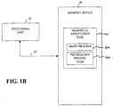
- the processing unit 22 and memory storage device 26 are discussed further below, in conjunction with FIG. 1B.
- the computing system 20 preferably also includes an external disk drive 32 and a hard disk drive 34.
- the external disk drive 32 is operable to receive, read and write to one or more external data storage devices, such as a floppy disk, tape, or compact disk, while the hard disk drive 34 is operable to provide fast access data storage and retrieval functions, in a known manner.
- the mouse 45 or another graphical input device together with the menu system described below in conjunction with FIGS. 2 through 5, provide a mechanism for user interaction with the computing system 20.
- the general purpose computing system 20 is running under a graphical user interface (GUI), such as Microsoft Windows, Presentation Manager or UNIX.
- GUI graphical user interface
- the alphanumeric keyboard 40 provides the usual functions and additionally serves to enter data.
- the processing unit 22 which may be embodied as a single processor or a number of processors operating in parallel, is preferably configured to implement the program code, discussed below in conjunction with FIGS. 6A and 6B, associated with the present invention which may be stored in the memory device 26.
- the memory device 26 preferably stores the program code for the graphical application tool 100, including a menu process 600 and one or more technology specific files 160, each discussed below in conjunction with FIG. 6.
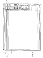
- FIG. 2 shows a menu bar 230 listing the names of typical pull-down menu options for a conventional computer-aided design (CAD) tool, such as the Design ArchitectTM computer-aided design (CAD) tool from Mentor Graphics, Inc.
- CAD computer-aided design
- FIG. 2 shows a menu bar 230 listing the names of typical pull-down menu options for a conventional computer-aided design (CAD) tool, such as the Design ArchitectTM computer-aided design (CAD) tool from Mentor Graphics, Inc.
- CAD computer-aided design
- FIG. 2 shows a menu bar 230 listing the names of typical pull-down menu options for a conventional computer-aided design (CAD) tool, such as the Design ArchitectTM computer-aided design (CAD) tool from Mentor Graphics, Inc.
- CAD computer-aided design
- FIG. 2 shows a menu bar 230 listing the names of typical pull-down menu options for a conventional computer-aided design (CAD) tool, such as the Design ArchitectTM computer-aided design (CAD) tool
- the graphical application tool 100 includes a menu 220 providing a user with access to core and custom commands and circuit component offerings.
- the menu 220 may be repositioned by a user, to minimize interference with the work space area 210.
- the menu 220 preferably includes a region 305 for indicating the particular technology, such as CMOS technology, with which the user is designing.
- the menu 220 includes a set oftab notebooks 310 for selecting various sets of core commands presented in a core command section 320.
- a core command is any software component provided by the manufacturer of the graphical application tool 100 to perform specified tasks.
- the menu 220 preferably includes a tab notebook for (i) session (S); (ii) route (R); (iii) text (T); and (iv) draw (D) core commands.
- the menu 220 preferably includes one or more custom command sections 330, 340 containing a user-defined subset of available custom commands. Custom commands are preferably bound to icon buttons in section 330, as well as to pull down menu options in section 340. In this manner, the user has easy access to those commands used most often.
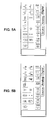
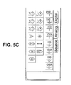
- the menu 220 preferably includes a set of tab notebooks 350 for selecting various sets of circuit component symbols presented in a device offering section 360. The circuit component symbols are placed in a drawing to represent an electrical component. As discussed below in conjunction with FIGS. 5A through 5C, the menu 220 preferably includes a tab notebook for (i) digital; (ii) analog; and (iii) source devices. Additional tab notebooks with further device collections could be provided as well.
- the core commands presented in the core command section 320 are context-determined so that commands appropriate to the current operating mode of the graphical application tool 100 are presented.
- the presented core commands are preferably appropriate for the schematic level.
- the presented core commands are preferably appropriate for the symbol level. For example, if a user is inserting a symbol into a drawing, the core commands presented in the text (T) tab notebook preferably include a command to add labels or properties to the inserted symbol.
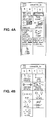
- FIG. 4A illustrates the collection of core commands associated with the session (S) tab notebook.
- the session (S) commands are not context-determined and apply globally to the computer-aided design (CAD) tool, such as file open and transcript (journal) commands.
- FIG. 4B illustrates the collection of core commands associated with the route (R) tab notebook.
- the route (R) commands allow a user to connect instantiated circuit symbols in a desired manner.
- FIG. 4C illustrates the collection of core commands associated with the text (T) tab notebook.
- the text (T) commands allow a user to manipulate labels and properties attached to symbols.
- FIG. 4D illustrates the collection of core commands associated with the draw (D) tab notebook.
- the draw (D) commands allow a user to add or manipulate graphical objects.
- the circuit component offerings presented in the device offering section 360 are technology-determined so that device offerings appropriate to the specified technology are presented.
- the user is preferably queried for the type of technology the user will be designing with, as discussed further below in conjunction with FIG. 6A.
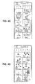
- FIGS. 5A through 5C illustrate the various device offerings for (i) digital; (ii) analog; and (iii) source devices, respectively, for CMOS technology.
- the menu process 600 monitors "mouse events" to initiate various software functions. For example, if a user clicks on a region of the menu 220, the menu process responds appropriately.
- the icons or buttons associated with each tab notebook are programmed so that if the user clicks on the mouse in the region of a given tab, the core commands associated with the tab will come forward.
- tabs are associated with a set of icons that are bound to an appropriate software function.
- multiple events may be bound to a single icon. For example, if a user clicks on an icon once with the mouse 45, one action will occur, and a different action is initiated upon a double click.
- both "undo” and “redo” or “zoom in and “zoom out” can be bound to the same icon, and separately initiated depending on the number of mouse clicks.
- separate actions can be initiated by each of the various buttons on the mouse 45.
- the menu process 600 preferably initiates a help function and presents a balloon message indicating the command, tool or symbol bound to a given icon.
- the menu process 600 initially queries the user to specify the technology the user will be working with during step 605 and thereby define an environment variable. Thereafter, the graphical application tool 100 will be launched during step 610, and inter-tool bi-directional communication channels or pipes are opened during step 615 for communication between the menu process 600 and other processes associated with the graphical application tool 100.
- An event handler is setup during step 620 to monitor for mouse events and other user events and to respond appropriately.
- the menu process 600 builds the menu 200, preferably from top to bottom.
- the core command tab menus 310, 320 are preferably built during step 625.
- the context-determined menu switching is enabled during step 630 by monitoring and responding to the event handler.
- the mouse events and core command functions are then bound to the appropriate icons during step 635 in sections 310 and 320 of the menu 220.
- the custom command icons 330 are built during step 640 and the mouse events and custom commands are then bound to the appropriate icons during step 650.
- the custom command pull-down menu 340 is built during step 655, and the appropriate custom commands are bound to the menu entries during step 660.
- the technology-specific device toolbar code is then loaded from the technology specific files 160 (FIG. 1B) during step 665, by reading the user-defined technology environment variable and reading the appropriate file from a predefined library path.
- the device offering tab menus 350, 360 are then built during step 670 and the mouse events and placement commands are then bound to each device icon during step 675.
- the menu 220 or interface created by the menu process 600 is displayed during step 680, before the menu process 600 commences monitoring events during step 685.
- CAD design ArchitectTM computer-aided design
- the graphical application tool 100 may be embodied as any computer-aided design (CAD) tool, spreadsheet package, or graphics drawing package, that graphically provides a user with a set of commands, tools and icons, which a user can graphically manipulate to generate, modify or analyze a work product in a work space area 210.
- CAD computer-aided design
Abstract
Description
- The present invention relates to a user interface for graphical application programs, such as computer-aided design (CAD) tools, and more particularly, to a method and apparatus for allowing a user to access commands, tools and icons offerings more efficiently, while maximizing workspace area.
- As computer-aided design (CAD) tools and other graphical applications programs have become more complex, the technical expertise required to use them has increased dramatically. Typically, users access the various functions and features provided by a graphical applications program by means of a menu bar listing the names of pull-down menu options. when a pull-down menu option is selected for display from the menu bar, an additional set of commands are presented to the user in a window or dialog box for further selection. Thus, in order for a user to perform a given task, the user must typically traverse several levels of command menus and implement multiple mouse clicks to locate a desired command.
- In addition, the additional windows or dialog boxes presented to a user for further selection, after selecting an initial pull-down menu option, tend to clutter the display, and the work space area in which the user is operating. The Composer™ computer-aided design (CAD) tool, commercially available from Cadence, Inc., for example, utilizes multiple floating windows to provide access to commands and device libraries. These floating windows cover the graphics area, forcing the user to repeatedly move the windows aside to view the schematic drawing hidden below. Furthermore, the use of multiple floating windows slows down the drafting process by increasing the time required to locate a desired command or circuit component icon, and increases the number of mouse clicks to perform a desired task.
- In order to increase user-efficiency, some graphical application programs, such as the Design Architect™ computer-aided design (CAD) tool, commercially available from Mentor Graphics, Inc., provide users with an additional menu of the frequently used commands and circuit component icons. In this manner, the user may access these commands and icons more efficiently without using the menu bar system. The additional menu in the Design Architect™ product, however, is in a fixed location, taking away a portion of the workspace available to a user. In addition, the additional menu in the Design Architect™ product selectively presents a user with either commands or circuit component icons at a given time. The user must select a library to view the available command or circuit component icon options.
- As apparent from the above-described deficiencies with conventional user interface systems for graphical application program, a need exists for a user interface that allows a user to access commands, tools and icons more efficiently, while maximizing work space area. A further need exists for a user interface that presents a user with available commands, tools and icons in a single menu. Yet another need exists for a user interface that is responsive to the current operating mode of the graphical application program and presents a user with appropriate selections depending on the current mode.
- According to one aspect of this invention there is provided a method of providing access to commands and symbolic icons in a graphical application program having a work space area, said method comprising the steps of: generating a menu of said command and symbolic icon options; positioning said menu in a screen location that does not interfere with said work space areal and providing a user with continuous access to each of said command and symbolic icon options on said menu.
- The method may comprise the step of organizing said symbolic icons into a plurality of categories, each separately accessible by a tab icon.
- Said symbolic icons may be specific to a technology being manipulated in said work space area.
- The method may comprise the step of binding multiple events to a single icon.
- According to another aspect of this invention a graphical application tool comprises: a set of command and symbolic icon options for generating a work product in a work space area; a graphical menu for presenting said set of command and symbolic icon options to a user, said graphical menu positioned in a screen location that does not interfere with said work space area; and a processor for providing said user with continuous access to each of said command and symbolic icon options on said graphical menu.
- Said commands viewable in said menu may be dependent upon an operating mode of said graphical application program.
- Said symbolic icons may be organized into a plurality of categories, each separately accessible by a tab icon.
- Said symbolic icons may be specific to a technology being manipulated in said work space area.
- Multiple events may be bound to a single icon.
- According to a further aspect of this invention an article of manufacture comprises: a computer readable medium having computer readable code embodied thereon, said computer readable program code comprising: a step to generate a menu of command and symbolic icon options for generating a work product in a work space area; a step to position said menu in a screen location that does not interfere with said work space areal and a step to provide a user with continuous access to each of said command and symbolic icon options on said menu.
- The article may comprise a step to organize said symbolic icons into a plurality of categories, each separately accessible by a tab icon.
- The article of manufacture may comprise a step to bind multiple events to a single icon.
- The article of manufacture may comprise a step to separately present said commands in said menu dependent upon an operating mode of said graphical application program.
- Generally, a user interface for a graphical application tool is disclosed. A graphical application tool is a software program, such as a computer-aided design (CAD) tool, a spreadsheet package, or a graphics drawing package, that graphically provides a user with a set of commands, tools and icons, which a user can graphically manipulate to generate, modify or analyze a work product in a work space area. The icons provided by the graphical application tool can include circuit components in a CAD system, clip art in a graphics drawing package or any other graphical representation or symbol to be placed in the work product. The graphical application tool includes a graphical user interface (GUI) to provide users with a menu of available commands, tools and icons.
- According to a further aspect of the invention, the menu provides access to the commands, tools and device offerings without interfering with the user's work space area. In the illustrative computer-aided design (CAD) tool embodiment, the menu preferably provides a user with access to core and custom commands and circuit component offerings. The menu may be repositioned by a user, to minimize interference with the work space area. The menu preferably includes a region for indicating the particular technology, such as CMOS technology, with which the user is designing. In addition, the menu includes a set of tab notebooks for selecting various sets of core commands presented in a core command section. In addition, the menu preferably includes one or more custom command sections containing a user-defined subset of available custom commands. In this manner, the user has easy access to those commands used most often. Finally, the menu preferably includes a set oftab notebooks for selecting various sets of circuit component symbols presented in a device offering section. The circuit component symbols are placed in a drawing to represent an electrical component.
- The core commands presented in the core command section are preferably context-determined so that commands appropriate to the current operating mode of the graphical application tool are presented. In other words, if the graphical application tool is performing a schematic operation, the presented core commands are preferably appropriate for the schematic level. Likewise, if the graphical application tool is performing a symbol operation, the presented core commands are preferably appropriate for the symbol level. For example, if a user is inserting a symbol into a drawing, the core commands presented in a text (T) tab notebook preferably include a command to add labels or properties to the inserted symbol.
- The circuit component offerings presented in the device offering section are preferably technology-determined so that device offerings appropriate to the specified technology are presented. In other words, when the graphical application tool is initiated, the user is preferably queried for the type of technology the user will be designing with.
- A more complete understanding of the present invention, as well as further features and advantages of the present invention, will be obtained by reference to the following detailed description and drawings.
-
- FIG. 1A is a perspective, cut-away view of a graphical application tool according to the present invention;
- FIG. 1B is a functional block diagram illustrating the processing and memory storage systems of the graphical application program of FIG. 1A;
- FIG. 2 illustrates a computer-aided design (CAD) tool monitor screen and its associated menu options;
- FIG. 3 illustrates the command and device menu of FIG. 2;
- FIGS. 4A through 4D illustrate the various tab notebook sets of core commands from the command and device menu of FIG. 3;
- FIGS. 5A through 5C illustrate the various tab notebook sets of device offerings from the command and device menu of FIG. 3; and
- FIGS 6A and 6B, collectively, are a flow chart describing an exemplary menu process implemented by the graphical application program of FIG. 1.
-
- A
graphical application tool 100 according to the present invention is shown in FIGS. 1 and 2. As used herein, agraphical application tool 100 is a software program, such as a computer-aided design (CAD) tool, a spreadsheet package, or a graphics drawing package, that graphically provides a user with a set of commands, tools and icons, which a user can graphically manipulate to generate, modify or analyze a work product in awork space area 210. In the illustrative implementation described herein, thegraphical application tool 100 is embodied as the Design Architect™ computer-aided design (CAD) tool, commercially available from Mentor Graphics, Inc., as modified herein to carry out the features and functions of the present invention. - As discussed below, the icons provided by the
graphical application tool 100 can include circuit components in a CAD system, clip art in a graphics drawing package or any other graphical representation or symbol to be placed in the work product. Thegraphical application tool 100 includes a graphical user interface (GUI) to provide users with a menu 220 (FIG. 2) of available commands, tools and icons. According to a feature of the present invention, themenu 220 provides access to the commands, tools and device offerings without interfering with the user'swork space area 210. - The present invention may be implemented using a general purpose computing device, such as the
computing device 20 shown in FIG. 1A, which may be embodied as a mainframe computer, a minicomputer, a workstation, a personal computer, or a networked combination of any of the foregoing. Thecomputing device 20 preferably includes agraphical display monitor 36, one ormore processing units 22, amemory storage device 26, such as random access memory, busses 24, aprinter 28, and one or more user interfaces, such as amouse 45 and akeyboard 40. Theprocessing unit 22 andmemory storage device 26 are discussed further below, in conjunction with FIG. 1B. - The
computing system 20 preferably also includes anexternal disk drive 32 and ahard disk drive 34. Theexternal disk drive 32 is operable to receive, read and write to one or more external data storage devices, such as a floppy disk, tape, or compact disk, while thehard disk drive 34 is operable to provide fast access data storage and retrieval functions, in a known manner. Themouse 45 or another graphical input device, together with the menu system described below in conjunction with FIGS. 2 through 5, provide a mechanism for user interaction with thecomputing system 20. The generalpurpose computing system 20 is running under a graphical user interface (GUI), such as Microsoft Windows, Presentation Manager or UNIX. Thealphanumeric keyboard 40 provides the usual functions and additionally serves to enter data. - As shown in FIG. 1B, the
processing unit 22, which may be embodied as a single processor or a number of processors operating in parallel, is preferably configured to implement the program code, discussed below in conjunction with FIGS. 6A and 6B, associated with the present invention which may be stored in thememory device 26. Thememory device 26 preferably stores the program code for thegraphical application tool 100, including amenu process 600 and one or more technologyspecific files 160, each discussed below in conjunction with FIG. 6. - FIG. 2 shows a
menu bar 230 listing the names of typical pull-down menu options for a conventional computer-aided design (CAD) tool, such as the Design Architect™ computer-aided design (CAD) tool from Mentor Graphics, Inc. For a full description of these options, refer to the Design Architect™ User's Manual. when a pull-down menu option is selected for display from themenu bar 230, an additional set of menu choices are presented for further selection. Thus, in order for a user to perform a given task using themenu bar 230, the user must traverse several levels of command menus and implement multiple mouse clicks to locate a desired command. - According to a feature of the present invention, shown in FIG. 2, the
graphical application tool 100 includes amenu 220 providing a user with access to core and custom commands and circuit component offerings. In a preferred embodiment, themenu 220 may be repositioned by a user, to minimize interference with thework space area 210. As shown in further detail in FIG. 3, themenu 220 preferably includes aregion 305 for indicating the particular technology, such as CMOS technology, with which the user is designing. In addition, themenu 220 includes aset oftab notebooks 310 for selecting various sets of core commands presented in acore command section 320. As used herein, a core command is any software component provided by the manufacturer of thegraphical application tool 100 to perform specified tasks. As discussed below in conjunction with FIGS. 4A through 4D, respectively, themenu 220 preferably includes a tab notebook for (i) session (S); (ii) route (R); (iii) text (T); and (iv) draw (D) core commands. - In addition, the
menu 220 preferably includes one or morecustom command sections section 330, as well as to pull down menu options insection 340. In this manner, the user has easy access to those commands used most often. Finally, themenu 220 preferably includes a set oftab notebooks 350 for selecting various sets of circuit component symbols presented in a device offering section 360. The circuit component symbols are placed in a drawing to represent an electrical component. As discussed below in conjunction with FIGS. 5A through 5C, themenu 220 preferably includes a tab notebook for (i) digital; (ii) analog; and (iii) source devices. Additional tab notebooks with further device collections could be provided as well. - In a preferred embodiment, the core commands presented in the
core command section 320 are context-determined so that commands appropriate to the current operating mode of thegraphical application tool 100 are presented. In other words, if thegraphical application tool 100 is performing a schematic operation, the presented core commands are preferably appropriate for the schematic level. Likewise, if thegraphical application tool 100 is performing a symbol operation, the presented core commands are preferably appropriate for the symbol level. For example, if a user is inserting a symbol into a drawing, the core commands presented in the text (T) tab notebook preferably include a command to add labels or properties to the inserted symbol. - FIG. 4A illustrates the collection of core commands associated with the session (S) tab notebook. The session (S) commands are not context-determined and apply globally to the computer-aided design (CAD) tool, such as file open and transcript (journal) commands. FIG. 4B illustrates the collection of core commands associated with the route (R) tab notebook. The route (R) commands allow a user to connect instantiated circuit symbols in a desired manner. FIG. 4C illustrates the collection of core commands associated with the text (T) tab notebook. The text (T) commands allow a user to manipulate labels and properties attached to symbols. FIG. 4D illustrates the collection of core commands associated with the draw (D) tab notebook. The draw (D) commands allow a user to add or manipulate graphical objects.
- In a preferred embodiment, the circuit component offerings presented in the device offering section 360 are technology-determined so that device offerings appropriate to the specified technology are presented. In other words, when the
graphical application tool 100 is initiated, the user is preferably queried for the type of technology the user will be designing with, as discussed further below in conjunction with FIG. 6A. FIGS. 5A through 5C illustrate the various device offerings for (i) digital; (ii) analog; and (iii) source devices, respectively, for CMOS technology. - The
menu process 600, shown in FIGS. 6A and 6B, monitors "mouse events" to initiate various software functions. For example, if a user clicks on a region of themenu 220, the menu process responds appropriately. As discussed further below, the icons or buttons associated with each tab notebook are programmed so that if the user clicks on the mouse in the region of a given tab, the core commands associated with the tab will come forward. Thus, tabs are associated with a set of icons that are bound to an appropriate software function. In a preferred embodiment, multiple events may be bound to a single icon. For example, if a user clicks on an icon once with themouse 45, one action will occur, and a different action is initiated upon a double click. For example, both "undo" and "redo" or "zoom in and "zoom out" can be bound to the same icon, and separately initiated depending on the number of mouse clicks. In an alternate implementation, separate actions can be initiated by each of the various buttons on themouse 45. In addition, if the mouse pointer remains idle over a region of themenu 220 for a predefined minimum period of time, themenu process 600 preferably initiates a help function and presents a balloon message indicating the command, tool or symbol bound to a given icon. - As shown in FIG. 6A, the
menu process 600 initially queries the user to specify the technology the user will be working with duringstep 605 and thereby define an environment variable. Thereafter, thegraphical application tool 100 will be launched duringstep 610, and inter-tool bi-directional communication channels or pipes are opened duringstep 615 for communication between themenu process 600 and other processes associated with thegraphical application tool 100. An event handler is setup duringstep 620 to monitor for mouse events and other user events and to respond appropriately. - Thereafter, the
menu process 600 builds the menu 200, preferably from top to bottom. Thus, the corecommand tab menus step 625. The context-determined menu switching, discussed above, is enabled duringstep 630 by monitoring and responding to the event handler. The mouse events and core command functions are then bound to the appropriate icons duringstep 635 insections menu 220. Thecustom command icons 330 are built duringstep 640 and the mouse events and custom commands are then bound to the appropriate icons during step 650. The custom command pull-down menu 340 is built duringstep 655, and the appropriate custom commands are bound to the menu entries duringstep 660. - The technology-specific device toolbar code is then loaded from the technology specific files 160 (FIG. 1B) during step 665, by reading the user-defined technology environment variable and reading the appropriate file from a predefined library path. The device
offering tab menus 350, 360 are then built duringstep 670 and the mouse events and placement commands are then bound to each device icon duringstep 675. Finally, themenu 220 or interface created by themenu process 600 is displayed duringstep 680, before themenu process 600 commences monitoring events duringstep 685. - It is to be understood that the embodiments and variations shown and described herein are merely illustrative of the principles of this invention and that various modifications may be implemented by those skilled in the art without departing from the scope and spirit of the invention. For example, although the
graphical application tool 100 has been illustrated herein as the Design Architect™ computer-aided design (CAD) tool, from Mentor Graphics, Inc., thegraphical application tool 100 may be embodied as any computer-aided design (CAD) tool, spreadsheet package, or graphics drawing package, that graphically provides a user with a set of commands, tools and icons, which a user can graphically manipulate to generate, modify or analyze a work product in awork space area 210.
Claims (10)
- A method of providing access to commands and symbolic icons in a graphical application program having a work space area, said method comprising the step of:generating a menu of said command and symbolic icon options;positioning said menu in a screen location that does not interfere with said work space area; andproviding a user with continuous access to each of said command and symbolic icon options on said menu.
- The method according to claim 1, further comprising the step of separately presenting core commands and custom commands on said menu.
- The method according to claim 1, further comprising the step of organizing said commands into a plurality of categories, each separately accessible by a tab icon.
- The method according to claim 1, further comprising the step of separately presenting said commands in said menu dependent upon an operating mode of said graphical application program.
- A graphical application tool comprising:a set of command and symbolic icon options for generating a work product in a work space area;a graphical menu for presenting said set of command and symbolic icon options to a user, said graphical menu positioned in a screen location that does not interfere with said work space area; anda processor for providing said user with continuous access to each of said command and symbolic icon options on said graphical menu.
- The tool according to claim 5, wherein said commands include core commands and custom commands which are separately presented on said menu.
- The tool according to claim 5, wherein said commands are organized into a plurality of categories, each separately accessible by a tab icon.
- An article of manufacture comprising:a computer readable medium having computer readable code embodied thereon, said computer readable program code comprising :a step to generate a menu of command and symbolic icon options for generating a work product in a work space area;a step to position said menu in a screen location that does not interfere with said work space area; anda step to provide a user with continuous access to each of said command and symbolic icon options on said menu.
- The article of manufacture according to claim 8, wherein said article of manufacture is a CD-ROM.
- The article of manufacture according to claim 8, wherein said article of manufacture is a diskette.
Applications Claiming Priority (2)
| Application Number | Priority Date | Filing Date | Title |
|---|---|---|---|
| US953497 | 1997-10-17 | ||
| US08/953,497 US6121965A (en) | 1997-10-17 | 1997-10-17 | User interface for graphical application tool |
Publications (2)
| Publication Number | Publication Date |
|---|---|
| EP0910007A2 true EP0910007A2 (en) | 1999-04-21 |
| EP0910007A3 EP0910007A3 (en) | 2003-02-05 |
Family
ID=25494092
Family Applications (1)
| Application Number | Title | Priority Date | Filing Date |
|---|---|---|---|
| EP98308358A Withdrawn EP0910007A3 (en) | 1997-10-17 | 1998-10-13 | User interface for graphical application tool |
Country Status (3)
| Country | Link |
|---|---|
| US (1) | US6121965A (en) |
| EP (1) | EP0910007A3 (en) |
| JP (1) | JPH11249780A (en) |
Cited By (27)
| Publication number | Priority date | Publication date | Assignee | Title |
|---|---|---|---|---|
| EP1672533A1 (en) * | 2004-12-20 | 2006-06-21 | Dassault Systèmes | Method and computer system for interacting with a database |
| EP2033115A2 (en) * | 2006-06-01 | 2009-03-11 | Microsoft Corporation | Modifying a chart |
| US7703036B2 (en) | 2004-08-16 | 2010-04-20 | Microsoft Corporation | User interface for displaying selectable software functionality controls that are relevant to a selected object |
| US7707255B2 (en) | 2003-07-01 | 2010-04-27 | Microsoft Corporation | Automatic grouping of electronic mail |
| US7716593B2 (en) | 2003-07-01 | 2010-05-11 | Microsoft Corporation | Conversation grouping of electronic mail records |
| US7739259B2 (en) | 2005-09-12 | 2010-06-15 | Microsoft Corporation | Integrated search and find user interface |
| US7747966B2 (en) | 2004-09-30 | 2010-06-29 | Microsoft Corporation | User interface for providing task management and calendar information |
| US7886290B2 (en) | 2005-06-16 | 2011-02-08 | Microsoft Corporation | Cross version and cross product user interface |
| US7895531B2 (en) | 2004-08-16 | 2011-02-22 | Microsoft Corporation | Floating command object |
| US8117542B2 (en) | 2004-08-16 | 2012-02-14 | Microsoft Corporation | User interface for displaying selectable software functionality controls that are contextually relevant to a selected object |
| US8201103B2 (en) | 2007-06-29 | 2012-06-12 | Microsoft Corporation | Accessing an out-space user interface for a document editor program |
| US8239882B2 (en) | 2005-08-30 | 2012-08-07 | Microsoft Corporation | Markup based extensibility for user interfaces |
| US8402096B2 (en) | 2008-06-24 | 2013-03-19 | Microsoft Corporation | Automatic conversation techniques |
| US8484578B2 (en) | 2007-06-29 | 2013-07-09 | Microsoft Corporation | Communication between a document editor in-space user interface and a document editor out-space user interface |
| US8627222B2 (en) | 2005-09-12 | 2014-01-07 | Microsoft Corporation | Expanded search and find user interface |
| US8762880B2 (en) | 2007-06-29 | 2014-06-24 | Microsoft Corporation | Exposing non-authoring features through document status information in an out-space user interface |
| US8799808B2 (en) | 2003-07-01 | 2014-08-05 | Microsoft Corporation | Adaptive multi-line view user interface |
| US9046983B2 (en) | 2009-05-12 | 2015-06-02 | Microsoft Technology Licensing, Llc | Hierarchically-organized control galleries |
| US9098837B2 (en) | 2003-06-26 | 2015-08-04 | Microsoft Technology Licensing, Llc | Side-by-side shared calendars |
| US9223477B2 (en) | 2004-08-16 | 2015-12-29 | Microsoft Technology Licensing, Llc | Command user interface for displaying selectable software functionality controls |
| US9542667B2 (en) | 2005-09-09 | 2017-01-10 | Microsoft Technology Licensing, Llc | Navigating messages within a thread |
| US9645698B2 (en) | 2004-08-16 | 2017-05-09 | Microsoft Technology Licensing, Llc | User interface for displaying a gallery of formatting options applicable to a selected object |
| US9665850B2 (en) | 2008-06-20 | 2017-05-30 | Microsoft Technology Licensing, Llc | Synchronized conversation-centric message list and message reading pane |
| US9727989B2 (en) | 2006-06-01 | 2017-08-08 | Microsoft Technology Licensing, Llc | Modifying and formatting a chart using pictorially provided chart elements |
| US9864489B2 (en) | 2004-08-16 | 2018-01-09 | Microsoft Corporation | Command user interface for displaying multiple sections of software functionality controls |
| US10437964B2 (en) | 2003-10-24 | 2019-10-08 | Microsoft Technology Licensing, Llc | Programming interface for licensing |
| US10445114B2 (en) | 2008-03-31 | 2019-10-15 | Microsoft Technology Licensing, Llc | Associating command surfaces with multiple active components |
Families Citing this family (101)
| Publication number | Priority date | Publication date | Assignee | Title |
|---|---|---|---|---|
| US6395718B1 (en) * | 1998-07-06 | 2002-05-28 | Guilford Pharmaceuticals Inc. | Pharmaceutical compositions and methods of inhibiting angiogenesis using naaladase inhibitors |
| US6533175B1 (en) * | 1999-05-28 | 2003-03-18 | Barcode Graphic Inc. | Automatic compliance-testing system for desktop designed consumer packaging |
| US6876960B1 (en) * | 1999-09-27 | 2005-04-05 | The Board Of Trustees Of The University Of Illinois | Method and apparatus for remotely assembling a physical system |
| JP4501196B2 (en) * | 1999-12-17 | 2010-07-14 | ブラザー工業株式会社 | Name designation font designation device and recording medium |
| US6952807B1 (en) * | 2000-01-31 | 2005-10-04 | Daimlerchrysler Corporation | Vehicle supply chain analysis system |
| US7000230B1 (en) | 2000-06-21 | 2006-02-14 | Microsoft Corporation | Network-based software extensions |
| US7155667B1 (en) * | 2000-06-21 | 2006-12-26 | Microsoft Corporation | User interface for integrated spreadsheets and word processing tables |
| US7346848B1 (en) | 2000-06-21 | 2008-03-18 | Microsoft Corporation | Single window navigation methods and systems |
| US6883168B1 (en) | 2000-06-21 | 2005-04-19 | Microsoft Corporation | Methods, systems, architectures and data structures for delivering software via a network |
| US6948135B1 (en) * | 2000-06-21 | 2005-09-20 | Microsoft Corporation | Method and systems of providing information to computer users |
| US7191394B1 (en) | 2000-06-21 | 2007-03-13 | Microsoft Corporation | Authoring arbitrary XML documents using DHTML and XSLT |
| US7624356B1 (en) * | 2000-06-21 | 2009-11-24 | Microsoft Corporation | Task-sensitive methods and systems for displaying command sets |
| US6564226B1 (en) | 2000-09-18 | 2003-05-13 | Daimlerchyrsler Corporation | Supplier management process with dynamically updated mapping |
| US8103496B1 (en) | 2000-10-26 | 2012-01-24 | Cypress Semicondutor Corporation | Breakpoint control in an in-circuit emulation system |
| US8149048B1 (en) | 2000-10-26 | 2012-04-03 | Cypress Semiconductor Corporation | Apparatus and method for programmable power management in a programmable analog circuit block |
| US6724220B1 (en) | 2000-10-26 | 2004-04-20 | Cyress Semiconductor Corporation | Programmable microcontroller architecture (mixed analog/digital) |
| US8160864B1 (en) | 2000-10-26 | 2012-04-17 | Cypress Semiconductor Corporation | In-circuit emulator and pod synchronized boot |
| US8176296B2 (en) | 2000-10-26 | 2012-05-08 | Cypress Semiconductor Corporation | Programmable microcontroller architecture |
| US7765095B1 (en) | 2000-10-26 | 2010-07-27 | Cypress Semiconductor Corporation | Conditional branching in an in-circuit emulation system |
| US7895530B2 (en) * | 2000-11-09 | 2011-02-22 | Change Tools, Inc. | User definable interface system, method, support tools, and computer program product |
| US6918091B2 (en) * | 2000-11-09 | 2005-07-12 | Change Tools, Inc. | User definable interface system, method and computer program product |
| US7443396B2 (en) * | 2000-11-29 | 2008-10-28 | National Instruments Corporation | Instrument having a virtual magnifying glass for displaying magnified portions of a signal waveform |
| US6717597B2 (en) * | 2000-12-15 | 2004-04-06 | Dassault Systemes | Contextual and dynamic command navigator for CAD and related systems |
| US7152213B2 (en) * | 2001-10-04 | 2006-12-19 | Infogation Corporation | System and method for dynamic key assignment in enhanced user interface |
| US7406674B1 (en) | 2001-10-24 | 2008-07-29 | Cypress Semiconductor Corporation | Method and apparatus for generating microcontroller configuration information |
| US7080327B1 (en) * | 2001-11-09 | 2006-07-18 | Cypress Semiconductor Corporation | Multi-level quick click icon hierarchy and/or activation |
| US8078970B1 (en) | 2001-11-09 | 2011-12-13 | Cypress Semiconductor Corporation | Graphical user interface with user-selectable list-box |
| US7526422B1 (en) | 2001-11-13 | 2009-04-28 | Cypress Semiconductor Corporation | System and a method for checking lock-step consistency between an in circuit emulation and a microcontroller |
| US8042093B1 (en) | 2001-11-15 | 2011-10-18 | Cypress Semiconductor Corporation | System providing automatic source code generation for personalization and parameterization of user modules |
| US7770113B1 (en) | 2001-11-19 | 2010-08-03 | Cypress Semiconductor Corporation | System and method for dynamically generating a configuration datasheet |
| US6966039B1 (en) * | 2001-11-19 | 2005-11-15 | Cypress Semiconductor Corp. | Method for facilitating microcontroller programming |
| US7844437B1 (en) | 2001-11-19 | 2010-11-30 | Cypress Semiconductor Corporation | System and method for performing next placements and pruning of disallowed placements for programming an integrated circuit |
| US7010773B1 (en) | 2001-11-19 | 2006-03-07 | Cypress Semiconductor Corp. | Method for designing a circuit for programmable microcontrollers |
| US8069405B1 (en) * | 2001-11-19 | 2011-11-29 | Cypress Semiconductor Corporation | User interface for efficiently browsing an electronic document using data-driven tabs |
| US7774190B1 (en) | 2001-11-19 | 2010-08-10 | Cypress Semiconductor Corporation | Sleep and stall in an in-circuit emulation system |
| US6715132B1 (en) * | 2001-11-19 | 2004-03-30 | Cypress Semiconductor Corporation | Datasheet browsing and creation with data-driven datasheet tabs within a microcontroller design tool |
| US6971004B1 (en) | 2001-11-19 | 2005-11-29 | Cypress Semiconductor Corp. | System and method of dynamically reconfiguring a programmable integrated circuit |
| JP2003168125A (en) * | 2001-11-29 | 2003-06-13 | Aakitekku:Kk | Plotting device and plotting program |
| US8103497B1 (en) | 2002-03-28 | 2012-01-24 | Cypress Semiconductor Corporation | External interface for event architecture |
| US7308608B1 (en) | 2002-05-01 | 2007-12-11 | Cypress Semiconductor Corporation | Reconfigurable testing system and method |
| US7761845B1 (en) | 2002-09-09 | 2010-07-20 | Cypress Semiconductor Corporation | Method for parameterizing a user module |
| US20040221265A1 (en) * | 2003-02-07 | 2004-11-04 | Smart Technologies Inc. | Connected and overlapped shapes enhancements |
| US7275216B2 (en) | 2003-03-24 | 2007-09-25 | Microsoft Corporation | System and method for designing electronic forms and hierarchical schemas |
| US7370066B1 (en) | 2003-03-24 | 2008-05-06 | Microsoft Corporation | System and method for offline editing of data files |
| US7415672B1 (en) | 2003-03-24 | 2008-08-19 | Microsoft Corporation | System and method for designing electronic forms |
| US7296017B2 (en) | 2003-03-28 | 2007-11-13 | Microsoft Corporation | Validation of XML data files |
| US7913159B2 (en) | 2003-03-28 | 2011-03-22 | Microsoft Corporation | System and method for real-time validation of structured data files |
| US7451392B1 (en) | 2003-06-30 | 2008-11-11 | Microsoft Corporation | Rendering an HTML electronic form by applying XSLT to XML using a solution |
| US7406660B1 (en) | 2003-08-01 | 2008-07-29 | Microsoft Corporation | Mapping between structured data and a visual surface |
| US7334187B1 (en) | 2003-08-06 | 2008-02-19 | Microsoft Corporation | Electronic form aggregation |
| US20050114818A1 (en) * | 2003-11-21 | 2005-05-26 | Lsi Logic Corporation | Chip design command processor |
| US8819072B1 (en) | 2004-02-02 | 2014-08-26 | Microsoft Corporation | Promoting data from structured data files |
| US7295049B1 (en) | 2004-03-25 | 2007-11-13 | Cypress Semiconductor Corporation | Method and circuit for rapid alignment of signals |
| US7496837B1 (en) | 2004-04-29 | 2009-02-24 | Microsoft Corporation | Structural editing with schema awareness |
| US7774620B1 (en) | 2004-05-27 | 2010-08-10 | Microsoft Corporation | Executing applications at appropriate trust levels |
| US8286125B2 (en) | 2004-08-13 | 2012-10-09 | Cypress Semiconductor Corporation | Model for a hardware device-independent method of defining embedded firmware for programmable systems |
| US8069436B2 (en) | 2004-08-13 | 2011-11-29 | Cypress Semiconductor Corporation | Providing hardware independence to automate code generation of processing device firmware |
| US7692636B2 (en) | 2004-09-30 | 2010-04-06 | Microsoft Corporation | Systems and methods for handwriting to a screen |
| US7712022B2 (en) | 2004-11-15 | 2010-05-04 | Microsoft Corporation | Mutually exclusive options in electronic forms |
| US7721190B2 (en) | 2004-11-16 | 2010-05-18 | Microsoft Corporation | Methods and systems for server side form processing |
| US7904801B2 (en) | 2004-12-15 | 2011-03-08 | Microsoft Corporation | Recursive sections in electronic forms |
| US8627354B2 (en) * | 2004-12-17 | 2014-01-07 | Martin E. Hellman | Tiered subscription broadcast system |
| US7937651B2 (en) | 2005-01-14 | 2011-05-03 | Microsoft Corporation | Structural editing operations for network forms |
| WO2006075335A2 (en) * | 2005-01-16 | 2006-07-20 | Zlango Ltd. | Communications network system and methods for using same |
| EP1844403A4 (en) * | 2005-01-16 | 2010-06-23 | Zlango Ltd | Iconic communication |
| US7332976B1 (en) | 2005-02-04 | 2008-02-19 | Cypress Semiconductor Corporation | Poly-phase frequency synthesis oscillator |
| US7725834B2 (en) | 2005-03-04 | 2010-05-25 | Microsoft Corporation | Designer-created aspect for an electronic form template |
| US20060224427A1 (en) * | 2005-03-30 | 2006-10-05 | International Business Machines Corporation | Method, system, and program product for individual and group work space allocation and utilization |
| US8010515B2 (en) | 2005-04-15 | 2011-08-30 | Microsoft Corporation | Query to an electronic form |
| US7400183B1 (en) | 2005-05-05 | 2008-07-15 | Cypress Semiconductor Corporation | Voltage controlled oscillator delay cell and method |
| US8089461B2 (en) | 2005-06-23 | 2012-01-03 | Cypress Semiconductor Corporation | Touch wake for electronic devices |
| US8200975B2 (en) | 2005-06-29 | 2012-06-12 | Microsoft Corporation | Digital signatures for network forms |
| US20070120875A1 (en) * | 2005-11-30 | 2007-05-31 | Symons Corporation | Computer aided design interface |
| US8001459B2 (en) | 2005-12-05 | 2011-08-16 | Microsoft Corporation | Enabling electronic documents for limited-capability computing devices |
| US8085067B1 (en) | 2005-12-21 | 2011-12-27 | Cypress Semiconductor Corporation | Differential-to-single ended signal converter circuit and method |
| EP1977617A2 (en) * | 2006-01-16 | 2008-10-08 | Zlango Ltd. | Activating an application |
| EP1977312A2 (en) * | 2006-01-16 | 2008-10-08 | Zlango Ltd. | Iconic communication |
| US8067948B2 (en) | 2006-03-27 | 2011-11-29 | Cypress Semiconductor Corporation | Input/output multiplexer bus |
| EP1936481A1 (en) * | 2006-12-22 | 2008-06-25 | Xelion B.V. | Menu in a user interface |
| US8219374B1 (en) | 2007-02-21 | 2012-07-10 | University Of Central Florida Research Foundation, Inc. | Symbolic switch/linear circuit simulator systems and methods |
| US8040266B2 (en) | 2007-04-17 | 2011-10-18 | Cypress Semiconductor Corporation | Programmable sigma-delta analog-to-digital converter |
| US8092083B2 (en) | 2007-04-17 | 2012-01-10 | Cypress Semiconductor Corporation | Temperature sensor with digital bandgap |
| US8026739B2 (en) | 2007-04-17 | 2011-09-27 | Cypress Semiconductor Corporation | System level interconnect with programmable switching |
| US9564902B2 (en) | 2007-04-17 | 2017-02-07 | Cypress Semiconductor Corporation | Dynamically configurable and re-configurable data path |
| US8130025B2 (en) | 2007-04-17 | 2012-03-06 | Cypress Semiconductor Corporation | Numerical band gap |
| US8516025B2 (en) | 2007-04-17 | 2013-08-20 | Cypress Semiconductor Corporation | Clock driven dynamic datapath chaining |
| US7737724B2 (en) | 2007-04-17 | 2010-06-15 | Cypress Semiconductor Corporation | Universal digital block interconnection and channel routing |
| US9720805B1 (en) | 2007-04-25 | 2017-08-01 | Cypress Semiconductor Corporation | System and method for controlling a target device |
| US8065653B1 (en) | 2007-04-25 | 2011-11-22 | Cypress Semiconductor Corporation | Configuration of programmable IC design elements |
| US8266575B1 (en) | 2007-04-25 | 2012-09-11 | Cypress Semiconductor Corporation | Systems and methods for dynamically reconfiguring a programmable system on a chip |
| US8049569B1 (en) | 2007-09-05 | 2011-11-01 | Cypress Semiconductor Corporation | Circuit and method for improving the accuracy of a crystal-less oscillator having dual-frequency modes |
| US20090089145A1 (en) * | 2007-09-28 | 2009-04-02 | Paul Edward Kent | Freight transport logistics performance modeling software system and process |
| US20090132939A1 (en) * | 2007-11-19 | 2009-05-21 | International Business Machines Corporation | Method and apparatus for a floating island for user navigation in an interactive environment |
| US8214763B2 (en) * | 2009-03-24 | 2012-07-03 | International Business Machines Corporation | Auto-positioning a context menu on a GUI |
| US9448964B2 (en) | 2009-05-04 | 2016-09-20 | Cypress Semiconductor Corporation | Autonomous control in a programmable system |
| US8689121B2 (en) * | 2010-05-06 | 2014-04-01 | Cadence Design Systems, Inc. | System and method for management of controls in a graphical user interface |
| USD741879S1 (en) | 2012-07-30 | 2015-10-27 | General Electric Company | Display screen or portion thereof with graphical user interface |
| US20150239270A1 (en) * | 2014-02-26 | 2015-08-27 | Sedny Attia | Adding Strength, Color, and Finish to 3D Printed Objects |
| US9798453B2 (en) * | 2014-03-17 | 2017-10-24 | Microsoft Technology Licensing, Llc | Beak ribbon system |
| USD843384S1 (en) * | 2017-01-05 | 2019-03-19 | Hulu, LLC | Display screen or portion thereof with graphical user interface |
| USD938960S1 (en) * | 2019-03-27 | 2021-12-21 | Teradyne, Inc. | Display screen or portion thereof with graphical user interface |
Citations (4)
| Publication number | Priority date | Publication date | Assignee | Title |
|---|---|---|---|---|
| WO1996010231A1 (en) * | 1994-09-27 | 1996-04-04 | Micrografx, Inc. | System and method for generating graphics charts |
| US5572648A (en) * | 1993-01-19 | 1996-11-05 | Canon Kabushiki Kaisha | System for simultaneously displaying a static tool palette having predefined windowing tool functions and a dynamic tool palette which changes windowing tool functons in accordance with a context of an executed application program |
| US5610828A (en) * | 1986-04-14 | 1997-03-11 | National Instruments Corporation | Graphical system for modelling a process and associated method |
| US5634095A (en) * | 1993-12-13 | 1997-05-27 | International Business Machines Corporation | Method of connecting objects on different notebook pages |
Family Cites Families (8)
| Publication number | Priority date | Publication date | Assignee | Title |
|---|---|---|---|---|
| US4823283A (en) * | 1986-10-14 | 1989-04-18 | Tektronix, Inc. | Status driven menu system |
| JP3168570B2 (en) * | 1989-11-08 | 2001-05-21 | 富士通株式会社 | Icon pattern automatic generation apparatus and method |
| US5299307A (en) * | 1990-08-17 | 1994-03-29 | Claris Corporation | Controls for drawing images on computer displays |
| US5542040A (en) * | 1993-12-15 | 1996-07-30 | International Business Machines Corporation | Display of dynamic data as a notebook |
| US5546528A (en) * | 1994-06-23 | 1996-08-13 | Adobe Systems Incorporated | Method of displaying multiple sets of information in the same area of a computer screen |
| US5625783A (en) * | 1994-12-13 | 1997-04-29 | Microsoft Corporation | Automated system and method for dynamic menu construction in a graphical user interface |
| US5627954A (en) * | 1995-05-05 | 1997-05-06 | Apple Computer, Inc. | Systems and methods for positioning a drawer title bar on a graphical user interface |
| US5710897A (en) * | 1995-08-15 | 1998-01-20 | International Business Machines Corporation | Manager for selecting a pointer graphics folder and customizing pointers |
-
1997
- 1997-10-17 US US08/953,497 patent/US6121965A/en not_active Expired - Lifetime
-
1998
- 1998-10-13 EP EP98308358A patent/EP0910007A3/en not_active Withdrawn
- 1998-10-19 JP JP29665898A patent/JPH11249780A/en active Pending
Patent Citations (4)
| Publication number | Priority date | Publication date | Assignee | Title |
|---|---|---|---|---|
| US5610828A (en) * | 1986-04-14 | 1997-03-11 | National Instruments Corporation | Graphical system for modelling a process and associated method |
| US5572648A (en) * | 1993-01-19 | 1996-11-05 | Canon Kabushiki Kaisha | System for simultaneously displaying a static tool palette having predefined windowing tool functions and a dynamic tool palette which changes windowing tool functons in accordance with a context of an executed application program |
| US5634095A (en) * | 1993-12-13 | 1997-05-27 | International Business Machines Corporation | Method of connecting objects on different notebook pages |
| WO1996010231A1 (en) * | 1994-09-27 | 1996-04-04 | Micrografx, Inc. | System and method for generating graphics charts |
Non-Patent Citations (5)
| Title |
|---|
| "ELIMINATING EXTRANEOUS SEPARATORS IN DYNAMICALLY OPDATED MENUS" IBM TECHNICAL DISCLOSURE BULLETIN, IBM CORP. NEW YORK, US, vol. 37, no. 7, 1 July 1994 (1994-07-01), pages 273-274, XP000455510 ISSN: 0018-8689 * |
| "PERFORMANCE-ORIENTED MENU CACHING FOR DYNAMICALLY BUILT MENUS" IBM TECHNICAL DISCLOSURE BULLETIN, IBM CORP. NEW YORK, US, vol. 37, no. 4A, 1 April 1994 (1994-04-01), pages 255-256, XP000446661 ISSN: 0018-8689 * |
| AQUINO, GRACE: "Visio 5 Integrates with Office 97" PCWORLD.COM, [Online] 12 August 1997 (1997-08-12), XP002210712 Retrieved from the Internet: <URL:http://www.pcworld.com/news/article/0 ,aid,5183,00.asp> [retrieved on 2002-08-22] * |
| DAN ROSE: "Windows® 1.x/2.x/3.x Abandonware" HTTP://WWW.SAFELINK.NET/DANROSE/AW-WIN3X-1 8.HTML, [Online] 21 January 2001 (2001-01-21), XP002210710 Retrieved from the Internet: <URL:http://www.safelink.net/danrose/aw-wi n3x-18.html> [retrieved on 2002-08-22] * |
| SENGSTACK, JEFF: "Visio Standard 5.0: Still the best flowcharting" PCWORLD.COM, [Online] 11 September 1997 (1997-09-11), XP002210711 Retrieved from the Internet: <URL:http://www.pcworld.com/news/article/0 ,aid,5320,00.asp> [retrieved on 2002-08-22] * |
Cited By (51)
| Publication number | Priority date | Publication date | Assignee | Title |
|---|---|---|---|---|
| US9715678B2 (en) | 2003-06-26 | 2017-07-25 | Microsoft Technology Licensing, Llc | Side-by-side shared calendars |
| US9098837B2 (en) | 2003-06-26 | 2015-08-04 | Microsoft Technology Licensing, Llc | Side-by-side shared calendars |
| US8150930B2 (en) | 2003-07-01 | 2012-04-03 | Microsoft Corporation | Automatic grouping of electronic mail |
| US10482429B2 (en) | 2003-07-01 | 2019-11-19 | Microsoft Technology Licensing, Llc | Automatic grouping of electronic mail |
| US7707255B2 (en) | 2003-07-01 | 2010-04-27 | Microsoft Corporation | Automatic grouping of electronic mail |
| US7716593B2 (en) | 2003-07-01 | 2010-05-11 | Microsoft Corporation | Conversation grouping of electronic mail records |
| US8799808B2 (en) | 2003-07-01 | 2014-08-05 | Microsoft Corporation | Adaptive multi-line view user interface |
| US10437964B2 (en) | 2003-10-24 | 2019-10-08 | Microsoft Technology Licensing, Llc | Programming interface for licensing |
| US9864489B2 (en) | 2004-08-16 | 2018-01-09 | Microsoft Corporation | Command user interface for displaying multiple sections of software functionality controls |
| US7895531B2 (en) | 2004-08-16 | 2011-02-22 | Microsoft Corporation | Floating command object |
| US9645698B2 (en) | 2004-08-16 | 2017-05-09 | Microsoft Technology Licensing, Llc | User interface for displaying a gallery of formatting options applicable to a selected object |
| US8117542B2 (en) | 2004-08-16 | 2012-02-14 | Microsoft Corporation | User interface for displaying selectable software functionality controls that are contextually relevant to a selected object |
| US9690448B2 (en) | 2004-08-16 | 2017-06-27 | Microsoft Corporation | User interface for displaying selectable software functionality controls that are relevant to a selected object |
| US10635266B2 (en) | 2004-08-16 | 2020-04-28 | Microsoft Technology Licensing, Llc | User interface for displaying selectable software functionality controls that are relevant to a selected object |
| US9690450B2 (en) | 2004-08-16 | 2017-06-27 | Microsoft Corporation | User interface for displaying selectable software functionality controls that are relevant to a selected object |
| US10521081B2 (en) | 2004-08-16 | 2019-12-31 | Microsoft Technology Licensing, Llc | User interface for displaying a gallery of formatting options |
| US10437431B2 (en) | 2004-08-16 | 2019-10-08 | Microsoft Technology Licensing, Llc | Command user interface for displaying selectable software functionality controls |
| US9223477B2 (en) | 2004-08-16 | 2015-12-29 | Microsoft Technology Licensing, Llc | Command user interface for displaying selectable software functionality controls |
| US7703036B2 (en) | 2004-08-16 | 2010-04-20 | Microsoft Corporation | User interface for displaying selectable software functionality controls that are relevant to a selected object |
| US7747966B2 (en) | 2004-09-30 | 2010-06-29 | Microsoft Corporation | User interface for providing task management and calendar information |
| US8839139B2 (en) | 2004-09-30 | 2014-09-16 | Microsoft Corporation | User interface for providing task management and calendar information |
| EP1672533A1 (en) * | 2004-12-20 | 2006-06-21 | Dassault Systèmes | Method and computer system for interacting with a database |
| CN1818901B (en) * | 2004-12-20 | 2011-07-13 | 达索系统公司 | Method and computer system for interacting with a database |
| US7886290B2 (en) | 2005-06-16 | 2011-02-08 | Microsoft Corporation | Cross version and cross product user interface |
| US8239882B2 (en) | 2005-08-30 | 2012-08-07 | Microsoft Corporation | Markup based extensibility for user interfaces |
| US9542667B2 (en) | 2005-09-09 | 2017-01-10 | Microsoft Technology Licensing, Llc | Navigating messages within a thread |
| US10248687B2 (en) | 2005-09-12 | 2019-04-02 | Microsoft Technology Licensing, Llc | Expanded search and find user interface |
| US9513781B2 (en) | 2005-09-12 | 2016-12-06 | Microsoft Technology Licensing, Llc | Expanded search and find user interface |
| US7739259B2 (en) | 2005-09-12 | 2010-06-15 | Microsoft Corporation | Integrated search and find user interface |
| US8627222B2 (en) | 2005-09-12 | 2014-01-07 | Microsoft Corporation | Expanded search and find user interface |
| US9727989B2 (en) | 2006-06-01 | 2017-08-08 | Microsoft Technology Licensing, Llc | Modifying and formatting a chart using pictorially provided chart elements |
| EP2033115A2 (en) * | 2006-06-01 | 2009-03-11 | Microsoft Corporation | Modifying a chart |
| US10482637B2 (en) | 2006-06-01 | 2019-11-19 | Microsoft Technology Licensing, Llc | Modifying and formatting a chart using pictorially provided chart elements |
| EP2033115A4 (en) * | 2006-06-01 | 2009-07-08 | Microsoft Corp | Modifying a chart |
| US8605090B2 (en) | 2006-06-01 | 2013-12-10 | Microsoft Corporation | Modifying and formatting a chart using pictorially provided chart elements |
| US8638333B2 (en) | 2006-06-01 | 2014-01-28 | Microsoft Corporation | Modifying and formatting a chart using pictorially provided chart elements |
| US10521073B2 (en) | 2007-06-29 | 2019-12-31 | Microsoft Technology Licensing, Llc | Exposing non-authoring features through document status information in an out-space user interface |
| US10592073B2 (en) | 2007-06-29 | 2020-03-17 | Microsoft Technology Licensing, Llc | Exposing non-authoring features through document status information in an out-space user interface |
| US10642927B2 (en) | 2007-06-29 | 2020-05-05 | Microsoft Technology Licensing, Llc | Transitions between user interfaces in a content editing application |
| US8201103B2 (en) | 2007-06-29 | 2012-06-12 | Microsoft Corporation | Accessing an out-space user interface for a document editor program |
| US8762880B2 (en) | 2007-06-29 | 2014-06-24 | Microsoft Corporation | Exposing non-authoring features through document status information in an out-space user interface |
| US8484578B2 (en) | 2007-06-29 | 2013-07-09 | Microsoft Corporation | Communication between a document editor in-space user interface and a document editor out-space user interface |
| US9098473B2 (en) | 2007-06-29 | 2015-08-04 | Microsoft Technology Licensing, Llc | Accessing an out-space user interface for a document editor program |
| US9619116B2 (en) | 2007-06-29 | 2017-04-11 | Microsoft Technology Licensing, Llc | Communication between a document editor in-space user interface and a document editor out-space user interface |
| US10445114B2 (en) | 2008-03-31 | 2019-10-15 | Microsoft Technology Licensing, Llc | Associating command surfaces with multiple active components |
| US9665850B2 (en) | 2008-06-20 | 2017-05-30 | Microsoft Technology Licensing, Llc | Synchronized conversation-centric message list and message reading pane |
| US10997562B2 (en) | 2008-06-20 | 2021-05-04 | Microsoft Technology Licensing, Llc | Synchronized conversation-centric message list and message reading pane |
| US8402096B2 (en) | 2008-06-24 | 2013-03-19 | Microsoft Corporation | Automatic conversation techniques |
| US9338114B2 (en) | 2008-06-24 | 2016-05-10 | Microsoft Technology Licensing, Llc | Automatic conversation techniques |
| US9046983B2 (en) | 2009-05-12 | 2015-06-02 | Microsoft Technology Licensing, Llc | Hierarchically-organized control galleries |
| US9875009B2 (en) | 2009-05-12 | 2018-01-23 | Microsoft Technology Licensing, Llc | Hierarchically-organized control galleries |
Also Published As
| Publication number | Publication date |
|---|---|
| EP0910007A3 (en) | 2003-02-05 |
| US6121965A (en) | 2000-09-19 |
| JPH11249780A (en) | 1999-09-17 |
Similar Documents
| Publication | Publication Date | Title |
|---|---|---|
| US6121965A (en) | User interface for graphical application tool | |
| US20200081594A1 (en) | Command User Interface for Displaying Selectable Software Functionality Controls | |
| US6489975B1 (en) | System and method for improved navigation between open windows in an application program using window tabs | |
| US5384911A (en) | Method of transferring programs from action oriented GUI paradigm to object oriented GUI paradigm | |
| US5345550A (en) | User-modifiable popup menus for object oriented behavior | |
| US6377286B1 (en) | Temporal desktop agent | |
| US5754809A (en) | Perspective windowing technique for computer graphical user interface | |
| US9864489B2 (en) | Command user interface for displaying multiple sections of software functionality controls | |
| US5428735A (en) | Method and apparatus for maintaining a record of set-creating data processing activities and associated data sets | |
| US6014140A (en) | Method and system for locating and displaying the position of a cursor contained within a page of a compound document | |
| US7849419B2 (en) | Computer-implemented graphical user interface previews | |
| US6411312B1 (en) | Method and system for transferring data using a graphical user interface | |
| US5867678A (en) | Method and system for searching and retrieving specific types of objects contained within a compound document | |
| EP1637986B1 (en) | An improved user interface for displaying selectable software functionality controls that are relevant to a selected object | |
| US8689137B2 (en) | Command user interface for displaying selectable functionality controls in a database application | |
| US5430839A (en) | Data entry screen method | |
| EP1086418B1 (en) | Method for dynamically displaying controls in a toolbar display based on control usage | |
| JP4255511B2 (en) | Interactive user interface | |
| US6828988B2 (en) | Interactive tooltip | |
| US5050105A (en) | Direct cursor-controlled access to multiple application programs and data | |
| US6078323A (en) | Method and system for rapidly accessing graphically displayed toolbar icons via toolbar accelerators | |
| EP0317480A2 (en) | Graphical menu tree | |
| WO1999066394A1 (en) | Method for adapting user interface elements based on historical usage | |
| JP3565441B2 (en) | Data processing system | |
| US7689938B2 (en) | Graphical calculator with hierarchical view of usage history |
Legal Events
| Date | Code | Title | Description |
|---|---|---|---|
| PUAI | Public reference made under article 153(3) epc to a published international application that has entered the european phase |
Free format text: ORIGINAL CODE: 0009012 |
|
| AK | Designated contracting states |
Kind code of ref document: A2 Designated state(s): AT BE CH CY DE DK ES FI FR GB GR IE IT LI LU MC NL PT SE |
|
| AX | Request for extension of the european patent |
Free format text: AL;LT;LV;MK;RO;SI |
|
| PUAL | Search report despatched |
Free format text: ORIGINAL CODE: 0009013 |
|
| AK | Designated contracting states |
Designated state(s): AT BE CH CY DE DK ES FI FR GB GR IE IT LI LU MC NL PT SE |
|
| AX | Request for extension of the european patent |
Extension state: AL LT LV MK RO SI |
|
| 17P | Request for examination filed |
Effective date: 20030725 |
|
| AKX | Designation fees paid |
Designated state(s): DE |
|
| 17Q | First examination report despatched |
Effective date: 20031030 |
|
| STAA | Information on the status of an ep patent application or granted ep patent |
Free format text: STATUS: THE APPLICATION IS DEEMED TO BE WITHDRAWN |
|
| 18D | Application deemed to be withdrawn |
Effective date: 20040310 |