EP0919835A2 - Random pulse type radar apparatus - Google Patents
Random pulse type radar apparatus Download PDFInfo
- Publication number
- EP0919835A2 EP0919835A2 EP98309588A EP98309588A EP0919835A2 EP 0919835 A2 EP0919835 A2 EP 0919835A2 EP 98309588 A EP98309588 A EP 98309588A EP 98309588 A EP98309588 A EP 98309588A EP 0919835 A2 EP0919835 A2 EP 0919835A2
- Authority
- EP
- European Patent Office
- Prior art keywords
- transmission
- signal
- radio wave
- modulation
- transmitter
- Prior art date
- Legal status (The legal status is an assumption and is not a legal conclusion. Google has not performed a legal analysis and makes no representation as to the accuracy of the status listed.)
- Withdrawn
Links
Images


Classifications
-
- G—PHYSICS
- G01—MEASURING; TESTING
- G01S—RADIO DIRECTION-FINDING; RADIO NAVIGATION; DETERMINING DISTANCE OR VELOCITY BY USE OF RADIO WAVES; LOCATING OR PRESENCE-DETECTING BY USE OF THE REFLECTION OR RERADIATION OF RADIO WAVES; ANALOGOUS ARRANGEMENTS USING OTHER WAVES
- G01S13/00—Systems using the reflection or reradiation of radio waves, e.g. radar systems; Analogous systems using reflection or reradiation of waves whose nature or wavelength is irrelevant or unspecified
- G01S13/02—Systems using reflection of radio waves, e.g. primary radar systems; Analogous systems
- G01S13/06—Systems determining position data of a target
- G01S13/08—Systems for measuring distance only
- G01S13/10—Systems for measuring distance only using transmission of interrupted, pulse modulated waves
- G01S13/26—Systems for measuring distance only using transmission of interrupted, pulse modulated waves wherein the transmitted pulses use a frequency- or phase-modulated carrier wave
- G01S13/28—Systems for measuring distance only using transmission of interrupted, pulse modulated waves wherein the transmitted pulses use a frequency- or phase-modulated carrier wave with time compression of received pulses
- G01S13/284—Systems for measuring distance only using transmission of interrupted, pulse modulated waves wherein the transmitted pulses use a frequency- or phase-modulated carrier wave with time compression of received pulses using coded pulses
- G01S13/288—Systems for measuring distance only using transmission of interrupted, pulse modulated waves wherein the transmitted pulses use a frequency- or phase-modulated carrier wave with time compression of received pulses using coded pulses phase modulated
-
- G—PHYSICS
- G01—MEASURING; TESTING
- G01S—RADIO DIRECTION-FINDING; RADIO NAVIGATION; DETERMINING DISTANCE OR VELOCITY BY USE OF RADIO WAVES; LOCATING OR PRESENCE-DETECTING BY USE OF THE REFLECTION OR RERADIATION OF RADIO WAVES; ANALOGOUS ARRANGEMENTS USING OTHER WAVES
- G01S13/00—Systems using the reflection or reradiation of radio waves, e.g. radar systems; Analogous systems using reflection or reradiation of waves whose nature or wavelength is irrelevant or unspecified
- G01S13/02—Systems using reflection of radio waves, e.g. primary radar systems; Analogous systems
- G01S13/06—Systems determining position data of a target
- G01S13/08—Systems for measuring distance only
- G01S13/10—Systems for measuring distance only using transmission of interrupted, pulse modulated waves
- G01S13/22—Systems for measuring distance only using transmission of interrupted, pulse modulated waves using irregular pulse repetition frequency
- G01S13/222—Systems for measuring distance only using transmission of interrupted, pulse modulated waves using irregular pulse repetition frequency using random or pseudorandom pulse repetition frequency
-
- G—PHYSICS
- G01—MEASURING; TESTING
- G01S—RADIO DIRECTION-FINDING; RADIO NAVIGATION; DETERMINING DISTANCE OR VELOCITY BY USE OF RADIO WAVES; LOCATING OR PRESENCE-DETECTING BY USE OF THE REFLECTION OR RERADIATION OF RADIO WAVES; ANALOGOUS ARRANGEMENTS USING OTHER WAVES
- G01S13/00—Systems using the reflection or reradiation of radio waves, e.g. radar systems; Analogous systems using reflection or reradiation of waves whose nature or wavelength is irrelevant or unspecified
- G01S13/02—Systems using reflection of radio waves, e.g. primary radar systems; Analogous systems
- G01S13/06—Systems determining position data of a target
- G01S13/08—Systems for measuring distance only
- G01S13/10—Systems for measuring distance only using transmission of interrupted, pulse modulated waves
- G01S13/26—Systems for measuring distance only using transmission of interrupted, pulse modulated waves wherein the transmitted pulses use a frequency- or phase-modulated carrier wave
- G01S13/28—Systems for measuring distance only using transmission of interrupted, pulse modulated waves wherein the transmitted pulses use a frequency- or phase-modulated carrier wave with time compression of received pulses
- G01S13/284—Systems for measuring distance only using transmission of interrupted, pulse modulated waves wherein the transmitted pulses use a frequency- or phase-modulated carrier wave with time compression of received pulses using coded pulses
- G01S13/286—Systems for measuring distance only using transmission of interrupted, pulse modulated waves wherein the transmitted pulses use a frequency- or phase-modulated carrier wave with time compression of received pulses using coded pulses frequency shift keyed
Definitions
- the present invention relates to a random pulse type radar apparatus for use in vessels, airplanes, automobiles, missiles and so forth.
- a conventional typical pulse radar apparatus mainly comprises a transmitter which transmits electromagnetic pulse wave energy at given time intervals, and a receiving unit which continuously monitors echo energy of the transmitted energy.
- the monitorable distance range of this system is a half the distance acquired by dividing the propagation speed of radio waves by the time interval of output pulses, this system cannot detect echo signals from a target which is located at a greater distance than this monitorable range.
- a CW radar which continuously sends out transmission radio waves and utilizes interference of the radio waves with their echoes from a target, has been put to a practical use. While the CW radar is mainly used to measure the moving speed of a target, the target position can be measured by additionally using frequency wobble. The CW radar is hardly used except for a special application.
- a pulse compression radar apparatus of the type that sends out a chirped pulse signal, which is one type of spectrum spread signal, or a BPSK signal of a digital code like a barker code, as an output signal in a short period of time is also used for a special application.
- This radar apparatus does not differ essentially from the typical pulse radar, and suffers a limited effect of reducing the peak power.
- a BPSK signal for example, if one tries to reduce the peak power by increasing the transmission time, physical measurement of echoes from a target at a very close range is not possible due to the short reciprocation time of radio waves (see Figures 6 and 7).
- the direct sequence (DS) system which employs PSK (Phase Shift Keying) modulation by using recursive code sequences and the frequency hopping (FH) system which switches transmission frequencies at a high speed have already been used widely as schemes of generating wide-band radio waves.
- PSK Phase Shift Keying
- FH frequency hopping
- a random pulse type radar apparatus comprises a transmitter for generating a hybrid type spectrum spread signal by simultaneously using two kinds of modulations which are phase shift keying (PSK) modulation for selecting a phase of a transmission radio wave in accordance with a pseudo noise digital code and outputting the transmission wave, and time hopping modulation for stopping transmission of a radio wave at random in accordance with the pseudo noise digital code; a receiving unit for selectively detecting an echo of a transmission signal radio wave, generated by the transmitter, from a target with a time delay; at least one a common antenna unit for use both for transmission and reception or antenna units installed close to each other and respectively serving single functional units; and a reception control unit for stopping an action of the receiving unit in a time zone in which the transmitter is outputting radio waves in accordance with the time hopping modulation, whereby a spatial distribution of an intensity of an echo of a transmitted radio wave is measured through computation of a cross-correlation function of a transmission signal and a reception signal.
- PSK phase shift keying
- Figures 1 and 2 exemplify a time sequence consisting of three kinds of modulation states of a positive phase (P), a negative phase (N) and no signal (-) and a circuit for generating the time sequence, both being similar to those disclosed in Japanese Patent No. 2655374 entitled "Spectrum Spread Communication Equipment”.
- the apparatus comprises two shift registers SR1,SR2 coupled to a local clock source which generates a clock signal CLOCK, as shown. Two bit parallel data is input into and shifted along the shift registers SR1,SR2, in response to the clock signal CLOCK.
- An XOR gate 1 is coupled to the last two bits of the shift register SR1 to determine the logical XOR of the data therein. This is fedback to the input of the shift register SR1 as well as to an output assigning circuit generally designated 10. Similarly, the last four bits of the shift register SR2 are logically XORed using respective XOR gates 2,3,4 to produce a single output bit which is fedback to the input of the shift register SR2 and the output assigning circuit 10.
- the output assigning circuit 10 includes an AND gate 14 and a NOR gate 15 which are coupled to the XOR gates 1,4 as shown.
- the output of the AND gate 14 is coupled to a plus bit output 11, which is used to control generation of the positive phase modulation states (P), whereas the output from the NOR gate 15 is coupled to a minus bit output 12, which is used to control generation of the negative phase modulation states (N).
- a second NOR gate 16 is coupled to the output of the AND gate 14 and the NOR gate 15 to produce the signal-less output 13, which is used to control generation of the no signal modulation state (-).
- this window is distributed at a pseudo random, so that about a half the energy of each echo can always be observed through this window in this example.
- Figure 3 exemplifies the simplest constitution that accomplishes the above-described function.
- the apparatus of Figure 3 includes a transmitter 20 which has an output coupled to an antenna unit 21 via a switch 22.
- the switch 22 is also coupled to a receiver 23 to transfer any received signals from the antenna unit 21 to the receiver 23.
- the receiver 23 includes a reception control unit coupled to a receiving unit 25 which is in turn coupled to a correlation detector 26.
- the reception control unit 24 detects a window signal from the transmitter and the received signal from the control switch 22.
- the correlation detector detects a code timing signal directly from the transmitter 20, as shown.
- the output of the transmitter is transmitted outside as a radio wave via an antenna unit which has a directivity.
- the transmitter sends a timing signal indicating a window (hereinafter called "window signal”) and a signal indicating the phase reference of a code to the receiver.
- the receiver receives a radio wave and supplies it, after down conversion, as an input to a correlation detector like a matched filter, which is comprised of an acoustic surface wave element, for measuring cross-correlation with a transmitted code.
- a correlation detector like a matched filter, which is comprised of an acoustic surface wave element, for measuring cross-correlation with a transmitted code.
- the window signal may show a non-negligible autocorrelation value depending on the scheme of forming the window signal, when ⁇ is other than 0.
- the utilization factor of transmission radio waves therefore varies for each phase of a code. As this utilization factor is predictable in advance, it can be compensated by adjusting the gain of the correlation detector or through digital processing after transmission.
- Figure 4 exemplifies a case where the output signal of the receiver is compensated through digital processing.
- the output of the receiver 23 is transferred to a multiplier 30.
- An additional address is output from the transmitter 20 to a memory compensation value device 31 which is in turn coupled to the multiplier 30.
- the compensation output signal is obtained from the multiplier 30.
- the digital output signal from the receiver is supplied to one input terminal of a multiplier.
- An output compensation value corresponding to each code phase, output from a memory, is supplied to the other input terminal of the multiplier in synchronism with a code timing signal output from the transmitter.
- a compensation output signal is computed as the multiplication output of the multiplier.
- the output compensation value contains the autocorrelation value of the window signal that has been used in transmission.
- the output compensation value is so set as to be large when the autocorrelation value is high or the window is narrow, and to be small when the autocorrelation value is low, and serves to cancel the influence of the window size on each code phase.
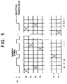
- Figure 5 exemplifies the constitution of a transmission signal in a case where FSK is used instead of PSK to constitute the transmission signal.
- the horizontal scale represents the time and either one of n types of frequencies and a signal-less state is assigned to each of m time slots ti.
- the window signal that is denoted by "W” becomes 1 in a signal-less state and indicates that none of the n types of frequencies is not transmitted in this state.
- this radar apparatus can significantly increase the transmission time of radio waves as compared with the conventional radar apparatus designed for position measurement, the radar apparatus can exhibit an effect of reducing the peak power of transmission radio waves and is easy to handle.
Abstract
Description
- The present invention relates to a random pulse type radar apparatus for use in vessels, airplanes, automobiles, missiles and so forth.
- A conventional typical pulse radar apparatus mainly comprises a transmitter which transmits electromagnetic pulse wave energy at given time intervals, and a receiving unit which continuously monitors echo energy of the transmitted energy.
- Because the monitorable distance range of this system is a half the distance acquired by dividing the propagation speed of radio waves by the time interval of output pulses, this system cannot detect echo signals from a target which is located at a greater distance than this monitorable range.
- This necessitates that the intensity of the output radio waves should be powerful enough to be dangerous to human bodies, such as radiation at a very close range. In this respect, radar usage has been managed through the license system.
- A CW radar, which continuously sends out transmission radio waves and utilizes interference of the radio waves with their echoes from a target, has been put to a practical use. While the CW radar is mainly used to measure the moving speed of a target, the target position can be measured by additionally using frequency wobble. The CW radar is hardly used except for a special application.
- A pulse compression radar apparatus of the type that sends out a chirped pulse signal, which is one type of spectrum spread signal, or a BPSK signal of a digital code like a barker code, as an output signal in a short period of time is also used for a special application. This radar apparatus does not differ essentially from the typical pulse radar, and suffers a limited effect of reducing the peak power. In a case of using a BPSK signal, for example, if one tries to reduce the peak power by increasing the transmission time, physical measurement of echoes from a target at a very close range is not possible due to the short reciprocation time of radio waves (see Figures 6 and 7).
- As pleasure-boats become popular, a radar apparatus which can be used without any danger and special knowledge is strongly demanded from a viewpoint of preventing sea accidents. Such a radar apparatus is not actually available on the market because there are no adequate technical schemes.
- It is known that the precision of measuring the distance by a radar becomes higher in proportion to the band width of radio waves that are generally used.
- In the field of radio communication, the direct sequence (DS) system which employs PSK (Phase Shift Keying) modulation by using recursive code sequences and the frequency hopping (FH) system which switches transmission frequencies at a high speed have already been used widely as schemes of generating wide-band radio waves.
- When radio waves of those systems are adapted for a radar usage, the peak of the transmission radio waves becomes minimum but the radio waves are output continuously. In a case of a radar apparatus in which its antenna is used as both the transmission antenna and reception antenna, however, masking of radio waves by the transmission signals makes it substantially impossible to receive very weak echoes.
- Accordingly, it is an object of the present invention to significantly reduce transmission peak power by employing a system, which is disclosed in Japanese Patent No. 2655374, entitled "Spectrum Spread Communication Equipment", by the same applicant as that of this invention and which sends out as an output signal a spectrum spread radio wave including a "signal-less period" set at a pseudo random and receives echoes in this "signal-less period".
- A random pulse type radar apparatus according to this invention comprises a transmitter for generating a hybrid type spectrum spread signal by simultaneously using two kinds of modulations which are phase shift keying (PSK) modulation for selecting a phase of a transmission radio wave in accordance with a pseudo noise digital code and outputting the transmission wave, and time hopping modulation for stopping transmission of a radio wave at random in accordance with the pseudo noise digital code; a receiving unit for selectively detecting an echo of a transmission signal radio wave, generated by the transmitter, from a target with a time delay; at least one a common antenna unit for use both for transmission and reception or antenna units installed close to each other and respectively serving single functional units; and a reception control unit for stopping an action of the receiving unit in a time zone in which the transmitter is outputting radio waves in accordance with the time hopping modulation, whereby a spatial distribution of an intensity of an echo of a transmitted radio wave is measured through computation of a cross-correlation function of a transmission signal and a reception signal.
- The invention, together with objects and advantages thereof, may best be understood by reference to the following description of the presently preferred embodiments together with the accompanying drawings in which:
- Figure 1 shows a time sequence consisting of three kinds of modulation states of a positive phase (P), a negative phase (N) and no signal (-) according to one embodiment of this invention;
- Figure 2 depicts a circuit for generating a time sequence consisting of three kinds of modulation states of a positive phase (P), a negative phase (N) and no signal (-) according to one embodiment of this invention;
- Figure 3 is a block diagram showing the simplest constitution that accomplishes the function of this embodiment;
- Figure 4 is a block diagram showing a constitution in a case where the output signal of a receiver according to this embodiment is compensated through digital processing;
- Figure 5 exemplifies the constitution of a transmission signal according to another embodiment of this invention wherein FSK (Frequency Shift Keying) is used instead of PSK to construct the transmission signal;
- Figure 6 is an explanatory diagram of a conventional pulse compression radar of a linear frequency modulation system; and
- Figure 7 is an explanatory diagram of a conventional coded pulse radar.
-
- The constitution and operation of a preferred embodiment of the present invention will now be described referring to Figures 1 through 5.
- Figures 1 and 2 exemplify a time sequence consisting of three kinds of modulation states of a positive phase (P), a negative phase (N) and no signal (-) and a circuit for generating the time sequence, both being similar to those disclosed in Japanese Patent No. 2655374 entitled "Spectrum Spread Communication Equipment".
- The apparatus comprises two shift registers SR1,SR2 coupled to a local clock source which generates a clock signal CLOCK, as shown. Two bit parallel data is input into and shifted along the shift registers SR1,SR2, in response to the clock signal CLOCK.
- An
XOR gate 1 is coupled to the last two bits of the shift register SR1 to determine the logical XOR of the data therein. This is fedback to the input of the shift register SR1 as well as to an output assigning circuit generally designated 10. Similarly, the last four bits of the shift register SR2 are logically XORed usingrespective XOR gates 2,3,4 to produce a single output bit which is fedback to the input of the shift register SR2 and the output assigning circuit 10. - The output assigning circuit 10 includes an AND gate 14 and a
NOR gate 15 which are coupled to theXOR gates 1,4 as shown. The output of the AND gate 14 is coupled to aplus bit output 11, which is used to control generation of the positive phase modulation states (P), whereas the output from theNOR gate 15 is coupled to a minus bit output 12, which is used to control generation of the negative phase modulation states (N). - A
second NOR gate 16 is coupled to the output of the AND gate 14 and theNOR gate 15 to produce thesignal-less output 13, which is used to control generation of the no signal modulation state (-). - In a case of using this time sequential signals as transmission radio waves of a radar, approximately a half of 127 chip codes are located in a signal-less period where transmission of a radio wave is stopped and detection of coming radio waves is possible (this period will be hereinafter called "window").
- As apparent from Figure 1, this window is distributed at a pseudo random, so that about a half the energy of each echo can always be observed through this window in this example.
- It is obvious that the aperture rate of this window can be adjusted almost arbitrarily by controlling the mixing ratio of signal-less segments in the time sequential signal in Figure 1.
- Figure 3 exemplifies the simplest constitution that accomplishes the above-described function.
- The apparatus of Figure 3 includes a
transmitter 20 which has an output coupled to anantenna unit 21 via aswitch 22. Theswitch 22 is also coupled to areceiver 23 to transfer any received signals from theantenna unit 21 to thereceiver 23. Thereceiver 23 includes a reception control unit coupled to a receivingunit 25 which is in turn coupled to acorrelation detector 26. The reception control unit 24 detects a window signal from the transmitter and the received signal from thecontrol switch 22. Similarly the correlation detector detects a code timing signal directly from thetransmitter 20, as shown. - In Figure 3, the output of the transmitter is transmitted outside as a radio wave via an antenna unit which has a directivity. At the same time, the transmitter sends a timing signal indicating a window (hereinafter called "window signal") and a signal indicating the phase reference of a code to the receiver.
- When the relationship between the phase reference of a code and the window is fixed previously, it is of course sufficient to supply just one of the two signals to the receiver.
- Only while the transmitter is not implementing transmission, the receiver receives a radio wave and supplies it, after down conversion, as an input to a correlation detector like a matched filter, which is comprised of an acoustic surface wave element, for measuring cross-correlation with a transmitted code.
- While the autocorrelation function of a window signal is ideally 1 when τ = 0 and 0 otherwise, the window signal may show a non-negligible autocorrelation value depending on the scheme of forming the window signal, when τ is other than 0.
- The utilization factor of transmission radio waves therefore varies for each phase of a code. As this utilization factor is predictable in advance, it can be compensated by adjusting the gain of the correlation detector or through digital processing after transmission.
- Figure 4 exemplifies a case where the output signal of the receiver is compensated through digital processing. In this case, the output of the
receiver 23 is transferred to amultiplier 30. An additional address is output from thetransmitter 20 to a memorycompensation value device 31 which is in turn coupled to themultiplier 30. The compensation output signal is obtained from themultiplier 30. - In Figure 4, the digital output signal from the receiver is supplied to one input terminal of a multiplier. An output compensation value corresponding to each code phase, output from a memory, is supplied to the other input terminal of the multiplier in synchronism with a code timing signal output from the transmitter. A compensation output signal is computed as the multiplication output of the multiplier.
- The output compensation value contains the autocorrelation value of the window signal that has been used in transmission. The output compensation value is so set as to be large when the autocorrelation value is high or the window is narrow, and to be small when the autocorrelation value is low, and serves to cancel the influence of the window size on each code phase.
- Figure 5 exemplifies the constitution of a transmission signal in a case where FSK is used instead of PSK to constitute the transmission signal.
- In Figure 5, the horizontal scale represents the time and either one of n types of frequencies and a signal-less state is assigned to each of m time slots ti.
- The window signal that is denoted by "W" becomes 1 in a signal-less state and indicates that none of the n types of frequencies is not transmitted in this state.
- In the period of W = 0, on the other hand, a signal of one of the frequencies, fj, is transmitted. The hatching in the diagram indicates the transmission state.
- Since this radar apparatus can significantly increase the transmission time of radio waves as compared with the conventional radar apparatus designed for position measurement, the radar apparatus can exhibit an effect of reducing the peak power of transmission radio waves and is easy to handle.
Claims (6)
- A random pulse type radar apparatus comprising:a transmitter for generating a hybrid type spectrum spread signal by simultaneously using two kinds of modulations which are phase shift keying (PSK) modulation for selecting a phase of a transmission radio wave in accordance with a pseudo noise digital code and outputting said transmission wave, and time hopping modulation for stopping transmission of a radio wave at random in accordance with said pseudo noise digital code;a receiving unit for selectively detecting an echo of a transmission signal radio wave, generated by said transmitter, from a target with a time delay;at least one a common antenna unit for use both for transmission and reception or antenna units installed close to each other and respectively serving single functional units; anda reception control unit for stopping an action of said receiving unit in a time zone in which said transmitter is outputting radio waves in accordance with said time hopping modulation,
whereby a spatial distribution of an intensity of an echo of a transmitted radio wave is measured through computation of a cross-correlation function of a transmission signal and a reception signal. - A random pulse type radar apparatus comprising:a transmitter for generating a hybrid type spectrum spread signal by simultaneously using two kinds of modulations which are frequency shift keying (FSK) modulation for selecting a frequency of a transmission radio wave in accordance with a pseudo noise digital code and outputting said transmission wave, and time hopping modulation for stopping transmission of a radio wave at random in accordance with said pseudo noise digital code;a receiving unit for selectively detecting an echo of a transmission signal radio wave, generated by said transmitter, from a target with a time delay;at least one common antenna unit for use both for transmission and reception or antenna units installed close to each other and respectively serving single functional units; anda reception control unit for stopping an action of said receiving unit in a time zone in which said transmitter is outputting radio waves in accordance with said time hopping modulation,
whereby a spatial distribution of an intensity of an echo of a transmitted radio wave is measured through computation of a cross-correlation function of a transmission signal and a reception signal. - The random pulse type radar apparatus according to claim 1, wherein as said hybrid type spectrum spread signal, a modulation state is determined by assigning a value of parallel data of two or more bits, obtained from values of individual sample points of PN (Pseudo Noise) code sequences of a binary or greater system, to a plurality of modulation states provided by adding a signal-less state added to individual phase states of phase shift keying (PSK).
- The random pulse type radar apparatus according to claim 3, wherein a constant portion of a time zone where each modulation state assigned is maintained, is further assigned to a signal-less state.
- The random pulse type radar apparatus according to any one of claims 1 to 4, wherein a reception sensitivity or a reception signal level is compensated in accordance with a value of an autocorrelation function indicated by digital codes used in said time hopping modulation.
- The random pulse type radar apparatus according to any one of claims 1 to 4, wherein a code sequence like a maximal linear code sequence (M-sequence) indicating an approximately constant autocorrelation value except when code phase matching occurs is used as digital codes used in said time hopping modulation.
Applications Claiming Priority (3)
| Application Number | Priority Date | Filing Date | Title |
|---|---|---|---|
| JP9342056A JP2942923B2 (en) | 1997-11-27 | 1997-11-27 | Random pulse type radar device |
| JP34205697 | 1997-11-27 | ||
| JP342056/97 | 1997-11-27 |
Publications (2)
| Publication Number | Publication Date |
|---|---|
| EP0919835A2 true EP0919835A2 (en) | 1999-06-02 |
| EP0919835A3 EP0919835A3 (en) | 1999-11-17 |
Family
ID=18350821
Family Applications (1)
| Application Number | Title | Priority Date | Filing Date |
|---|---|---|---|
| EP98309588A Withdrawn EP0919835A3 (en) | 1997-11-27 | 1998-11-24 | Random pulse type radar apparatus |
Country Status (3)
| Country | Link |
|---|---|
| US (1) | US6381261B1 (en) |
| EP (1) | EP0919835A3 (en) |
| JP (1) | JP2942923B2 (en) |
Cited By (9)
| Publication number | Priority date | Publication date | Assignee | Title |
|---|---|---|---|---|
| EP1235079A3 (en) * | 2001-02-22 | 2004-06-23 | Robert Bosch Gmbh | Method of reducing interference in a radar device and radar apparatus |
| WO2005006014A1 (en) * | 2003-07-07 | 2005-01-20 | Mitsubishi Electric Information Technology Centre Europe B.V. | Generations of sequences of waveforms |
| WO2006048604A1 (en) * | 2004-11-04 | 2006-05-11 | Instro Precision Limited | Optical correlation apparatus and method |
| US7165009B2 (en) * | 2003-09-16 | 2007-01-16 | Tyco Electronics Amp Gmbh | Apparatus, method and articles of manufacture for velocity and bearing determination of an object |
| CN101296052B (en) * | 2007-04-29 | 2013-01-02 | 大唐联诚信息系统技术有限公司 | Anti-communication reconnaissance and interception method and device |
| US10698099B2 (en) * | 2017-10-18 | 2020-06-30 | Leolabs, Inc. | Randomized phase and amplitude radar codes for space object tracking |
| US10921427B2 (en) | 2018-02-21 | 2021-02-16 | Leolabs, Inc. | Drone-based calibration of a phased array radar |
| US11024958B2 (en) | 2015-04-08 | 2021-06-01 | Sri International | 1D phased array antenna for radar and communications |
| US11378685B2 (en) | 2019-02-27 | 2022-07-05 | Leolabs, Inc. | Systems, devices, and methods for determining space object attitude stabilities from radar cross-section statistics |
Families Citing this family (28)
| Publication number | Priority date | Publication date | Assignee | Title |
|---|---|---|---|---|
| GB2353155A (en) * | 1999-08-05 | 2001-02-14 | Mitsubishi Electric Inf Tech | A random binary signal generator with a narrowed autocorrelation function |
| JP4595197B2 (en) * | 2000-12-12 | 2010-12-08 | 株式会社デンソー | Distance measuring device |
| DE60223490T2 (en) * | 2002-01-21 | 2008-09-18 | Mitsubishi Denki K.K. | Generation of a sequence of pulse trains |
| US7020177B2 (en) * | 2002-10-01 | 2006-03-28 | Intel Corporation | Method and apparatus to transfer information |
| US7035040B2 (en) * | 2003-05-16 | 2006-04-25 | Imation Corp. | Sequenced time-based servo techniques |
| US6952317B2 (en) * | 2003-06-17 | 2005-10-04 | Imation Corp. | Amplitude-based servo patterns for magnetic media |
| US7038872B2 (en) * | 2003-11-10 | 2006-05-02 | Imation Corp. | Servo patterns with inherent track ID |
| US7038871B2 (en) * | 2003-11-10 | 2006-05-02 | Imation Corp. | Multi-band servo patterns with inherent track ID |
| US7142381B2 (en) * | 2003-11-10 | 2006-11-28 | Imation Corp. | Servo writing devices for creating servo patterns with inherent track ID |
| JP2005265461A (en) * | 2004-03-16 | 2005-09-29 | Fujitsu Ten Ltd | Radar system |
| US7071866B2 (en) * | 2004-03-26 | 2006-07-04 | Northrop Grumman Corporation | 2-d range hopping spread spectrum encoder/decoder system for RF tags |
| US7095583B2 (en) * | 2004-06-02 | 2006-08-22 | Imation Corp. | Dual mode servo pattern |
| JP4615904B2 (en) | 2004-06-14 | 2011-01-19 | 富士通株式会社 | Radar equipment |
| US7199958B2 (en) * | 2004-08-25 | 2007-04-03 | Imation Corp. | Servo head with varying write gap width |
| KR100644627B1 (en) * | 2004-09-14 | 2006-11-10 | 삼성전자주식회사 | Method for encoding a sound field control information and method for processing therefor |
| US20060133338A1 (en) * | 2004-11-23 | 2006-06-22 | Interdigital Technology Corporation | Method and system for securing wireless communications |
| US7466510B2 (en) * | 2005-06-03 | 2008-12-16 | Imation Corp. | Distributed servo patterns for data storage media |
| US7379254B2 (en) * | 2005-06-29 | 2008-05-27 | Imation Corp. | Mixed frequency amplitude-based servo pattern |
| US7436622B2 (en) * | 2006-07-31 | 2008-10-14 | Imation Corp. | Concurrent servo and data track writing |
| FR2969436A1 (en) * | 2010-12-21 | 2012-06-22 | France Telecom | PROTECTION AGAINST THE DETECTION OF ALERT SIGNALS |
| AU2012280946B2 (en) | 2011-07-13 | 2015-10-08 | Clarke Mosquito Control Products, Inc. | Insecticidal compositions and methods of using the same |
| US9075138B2 (en) * | 2012-04-23 | 2015-07-07 | Massachusetts Institute Of Technology | Efficient pulse Doppler radar with no blind ranges, range ambiguities, blind speeds, or Doppler ambiguities |
| US9274542B2 (en) * | 2013-11-27 | 2016-03-01 | Raytheon Company | Creation of radio waveforms according to a probability distribution using weighted parameters |
| US9638789B2 (en) * | 2014-01-30 | 2017-05-02 | Infineon Technologies Ag | Method, device and system for processing radar signals |
| US9753766B2 (en) | 2014-11-25 | 2017-09-05 | Raytheon Company | Apparatus and method for allocating resources using prioritization of requests and updating of requests |
| DE102017206236A1 (en) * | 2017-04-11 | 2018-10-11 | Fraunhofer-Gesellschaft zur Förderung der angewandten Forschung e.V. | SPECIFIC HOPPING PATTERN FOR TELEGRAM SPLITTING |
| KR102147219B1 (en) * | 2019-03-25 | 2020-08-24 | 셀파이엔씨(주) | Apparatus for ground-penetrating radar survey |
| CN110703279B (en) * | 2019-09-16 | 2021-12-07 | 西安空间无线电技术研究所 | Satellite navigation signal generation method based on chip-level pulse time hopping |
Citations (2)
| Publication number | Priority date | Publication date | Assignee | Title |
|---|---|---|---|---|
| EP0336273A2 (en) * | 1988-04-02 | 1989-10-11 | Daimler-Benz Aerospace Aktiengesellschaft | Pulse Doppler radar |
| EP0714035A1 (en) * | 1994-11-24 | 1996-05-29 | The Furukawa Electric Co., Ltd. | Radar device |
Family Cites Families (5)
| Publication number | Priority date | Publication date | Assignee | Title |
|---|---|---|---|---|
| JP2655374B2 (en) | 1991-10-25 | 1997-09-17 | 株式会社ジーデイーエス | Spread spectrum communication equipment |
| US5610907A (en) * | 1994-07-29 | 1997-03-11 | Barrett; Terence W. | Ultrafast time hopping CDMA-RF communications: code-as-carrier, multichannel operation, high data rate operation and data rate on demand |
| US5677927A (en) * | 1994-09-20 | 1997-10-14 | Pulson Communications Corporation | Ultrawide-band communication system and method |
| JP3307217B2 (en) * | 1996-03-01 | 2002-07-24 | 株式会社豊田自動織機 | Receiver for spread spectrum communication system |
| US5828333A (en) * | 1997-01-21 | 1998-10-27 | Northrop Grumman Corporation | Multiple access diplex doppler radar |
-
1997
- 1997-11-27 JP JP9342056A patent/JP2942923B2/en not_active Expired - Fee Related
-
1998
- 1998-11-23 US US09/197,696 patent/US6381261B1/en not_active Expired - Fee Related
- 1998-11-24 EP EP98309588A patent/EP0919835A3/en not_active Withdrawn
Patent Citations (2)
| Publication number | Priority date | Publication date | Assignee | Title |
|---|---|---|---|---|
| EP0336273A2 (en) * | 1988-04-02 | 1989-10-11 | Daimler-Benz Aerospace Aktiengesellschaft | Pulse Doppler radar |
| EP0714035A1 (en) * | 1994-11-24 | 1996-05-29 | The Furukawa Electric Co., Ltd. | Radar device |
Cited By (14)
| Publication number | Priority date | Publication date | Assignee | Title |
|---|---|---|---|---|
| EP1235079A3 (en) * | 2001-02-22 | 2004-06-23 | Robert Bosch Gmbh | Method of reducing interference in a radar device and radar apparatus |
| WO2005006014A1 (en) * | 2003-07-07 | 2005-01-20 | Mitsubishi Electric Information Technology Centre Europe B.V. | Generations of sequences of waveforms |
| US7408499B2 (en) | 2003-07-07 | 2008-08-05 | Mitsubishi Electric Corporation | Generations of sequences of waveforms |
| US7165009B2 (en) * | 2003-09-16 | 2007-01-16 | Tyco Electronics Amp Gmbh | Apparatus, method and articles of manufacture for velocity and bearing determination of an object |
| WO2006048604A1 (en) * | 2004-11-04 | 2006-05-11 | Instro Precision Limited | Optical correlation apparatus and method |
| US8098712B2 (en) | 2004-11-04 | 2012-01-17 | Instro Precision Limited | Optical correlation apparatus and method |
| CN101296052B (en) * | 2007-04-29 | 2013-01-02 | 大唐联诚信息系统技术有限公司 | Anti-communication reconnaissance and interception method and device |
| US11024958B2 (en) | 2015-04-08 | 2021-06-01 | Sri International | 1D phased array antenna for radar and communications |
| US11539130B2 (en) | 2015-04-08 | 2022-12-27 | Sri International | 1D phased array antenna for radar and communications |
| US10698099B2 (en) * | 2017-10-18 | 2020-06-30 | Leolabs, Inc. | Randomized phase and amplitude radar codes for space object tracking |
| US11327168B2 (en) | 2017-10-18 | 2022-05-10 | Leolabs, Inc. | Randomized phase and amplitude radar codes for space object tracking |
| AU2018350835B2 (en) * | 2017-10-18 | 2023-10-05 | Leolabs, Inc. | Randomized phase and amplitude radar codes for space object tracking |
| US10921427B2 (en) | 2018-02-21 | 2021-02-16 | Leolabs, Inc. | Drone-based calibration of a phased array radar |
| US11378685B2 (en) | 2019-02-27 | 2022-07-05 | Leolabs, Inc. | Systems, devices, and methods for determining space object attitude stabilities from radar cross-section statistics |
Also Published As
| Publication number | Publication date |
|---|---|
| JPH11160421A (en) | 1999-06-18 |
| US6381261B1 (en) | 2002-04-30 |
| JP2942923B2 (en) | 1999-08-30 |
| EP0919835A3 (en) | 1999-11-17 |
Similar Documents
| Publication | Publication Date | Title |
|---|---|---|
| EP0919835A2 (en) | Random pulse type radar apparatus | |
| US11175377B2 (en) | PMCW-PMCW interference mitigation | |
| JP2990097B2 (en) | Continuous-wave wide-band precision ranging radar equipment. | |
| EP0631153B1 (en) | Radar system utilizing chaotic coding | |
| US6271786B1 (en) | Random noise radar target detection device | |
| US5265121A (en) | Spread spectrum coherent processor | |
| US20180095163A1 (en) | Phase-modulated continuous wave radar system (with prbs codes) | |
| US20030090405A1 (en) | Spread spectrum radar with leak compensation at baseband | |
| JP2009522575A5 (en) | ||
| AU2002333123A1 (en) | Spread spectrum radar with leak compensation at baseband | |
| US5337052A (en) | Random binary modulated sensor | |
| CA2010959A1 (en) | Ranging Systems | |
| Diaz et al. | Using Golay complementary sequences for multi-mode ultrasonic operation | |
| JP2006510013A (en) | Method and apparatus for measuring distance | |
| US3868686A (en) | Range tracking device for a portable attack warning radar | |
| GB2048536A (en) | Intruder detection system | |
| JP3611115B2 (en) | Ranging device and radar device equipped with the ranging device | |
| JP3020150B2 (en) | Spread spectrum radar equipment | |
| JPH03174835A (en) | Spread spectrum communication system | |
| JP2001183447A (en) | Range finding method and device | |
| GB2242803A (en) | Microwave alarm sensor | |
| US5140330A (en) | Continuous emission radar device for determining, at short range, the relative positions of a missile and a vehicle to which the device is fitted | |
| JP2681638B2 (en) | Direct spread spectrum radar system | |
| JPS6225276A (en) | Obstacle detecting device | |
| RU2677853C9 (en) | Radar ranging station with quasi-continuous noise signal |
Legal Events
| Date | Code | Title | Description |
|---|---|---|---|
| PUAI | Public reference made under article 153(3) epc to a published international application that has entered the european phase |
Free format text: ORIGINAL CODE: 0009012 |
|
| AK | Designated contracting states |
Kind code of ref document: A2 Designated state(s): AT BE CH CY DE DK ES FI FR GB GR IE IT LI LU MC NL PT SE |
|
| AX | Request for extension of the european patent |
Free format text: AL;LT;LV;MK;RO;SI |
|
| PUAL | Search report despatched |
Free format text: ORIGINAL CODE: 0009013 |
|
| AK | Designated contracting states |
Kind code of ref document: A3 Designated state(s): AT BE CH CY DE DK ES FI FR GB GR IE IT LI LU MC NL PT SE |
|
| AX | Request for extension of the european patent |
Free format text: AL;LT;LV;MK;RO;SI |
|
| AKX | Designation fees paid | ||
| REG | Reference to a national code |
Ref country code: DE Ref legal event code: 8566 |
|
| STAA | Information on the status of an ep patent application or granted ep patent |
Free format text: STATUS: THE APPLICATION IS DEEMED TO BE WITHDRAWN |
|
| 18D | Application deemed to be withdrawn |
Effective date: 20000518 |