-
This invention relates to a digital sound signal
transmitting apparatus for performing compression
encoding on a digitized sound signal, and then
transmitting the resultant encoded data via a predetermined
medium, and a digital sound signal receiving
apparatus for receiving data including the encoded
data output from the transmitting apparatus, and then
performing decompression decoding corresponding to the
compression encoding.
-
There are known various types of conventional
digital sound signal transmitting apparatuses and
receiving apparatuses. These digital sound signal
transmitting apparatuses and receiving apparatuses
include magnetic recording/reproducing apparatuses,
data transmitting/receiving apparatuses, encoded-image
recording apparatuses capable of recording data, by
printing, on a printing/recording medium in the form
of an optically readable encoded image, and reading
apparatuses for reading the recorded data. Those
apparatuses employ various types of compression
encoding methods to save the amount of data to be
transmitted and received or to realize high speed
transmission.
-
In many cases where such compression encoding
methods are employed, to secure desired reproduction
quality for a sound when it is received, a sound band
corresponding to the reproduction quality is set
for the sound and compression encoding of a high
compression ratio and high quality is performed on
the sound before transmitting it.
-
Accordingly, the band of the to-be-transmitted
sound is actually fixed. To obtain a higher
compression ratio with the reproduction band of the
sound secured, it is necessary to slightly sacrifice
the number of bits to be quantized during digitization
or the S/N ratio, and a compression encoding method for
this purpose is being contrived.
-
It is a well known matter in the digital data
compression encoding that to obtain both a high quality
and a high compression ratio is difficult and they have
a trade-off relationship.
-
In light of this, Japanese Patent Application
KOKAI Publication No. 61-43796, for example, proposes
a single apparatus equipped with a plurality of
compression encoding means for performing different
compression encoding processes. In this apparatus,
an optimal one is selected from the plurality of
compression encoding means in accordance with the type
of a sound or a request from the user, in order to
transmit and receive digitised sound signals.
-
However, the proposed apparatus, which employs the
plural compression encoding means, is inevitably large
and expensive, and therefore leaves much to be improved.
-
Further, Japanese Patent Application KOKAI
Publication No. 5-335968, for example, proposes
an apparatus, in which a clock signal is directly
extracted from to-be-transmitted digital data, the
frequency of the extracted clock signal is converted
into a low sampling frequency, the digital data is
encoded on the basis of the converted sampling
frequency, and the resultant encoded data is
transmitted. This publication, however, does not refer
to the number of data samples for encoding by the
encoding means.
-
The invention has been developed under the above-described
circumstances, and is aimed at providing
a digital sound signal transmitting apparatus and
receiving apparatus which each employ only a single
compression encoding means but can enhance either the
quality of to-be-transmitted and to-be-received digital
sound signals, or the compression ratios of them in
accordance with the purpose, and wherein an increase in
size and manufacturing cost is minimized.
-
According to an aspect of the present invention,
there is provided a digital sound signal transmitting
apparatus for compression encoding a digitized sound
signal into encoded data, and transmitting the encoded
data via a predetermined medium, comprising:
- a frequency band setting unit for setting a
frequency band for a to-be-transmitted digital sound
signal, and determining a cut-off frequency and a
re-sampling frequency for the digital sound signal
on the basis of the set frequency band;
- an adaptive band limiting filter for adaptively
filtering the to-be-transmitted digital sound signal on
the basis of the cut-off frequency determined by the
frequency band setting unit;
- a re-sampling unit for re-sampling the digital
sound signal having passed through the adaptive band
limiting filter, using the re-sampling frequency
determined by the frequency band setting unit; and
- a compression encoding unit for compression
encoding the digital sound signal re-sampled by the
re-sampling unit, in units of a predetermined number of
data samples, thereby creating encoded data.
-
-
According to another aspect of the present
invention, there is provided a digital sound signal
receiving apparatus for receiving data which contains
encoded data transmitted from a digital sound signal
transmitting apparatus including: a frequency band
setting unit for setting a frequency band for a to-be-transmitted
digital sound signal, and determining a
cut-off frequency and a re-sampling frequency for the
digital sound signal on the basis of the set frequency
band; an adaptive band limiting filter for adaptively
filtering the to-be-transmitted digital sound signal on
the basis of the cut-off frequency determined by the
frequency band setting unit; a re-sampling unit for
re-sampling the digital sound signal having passed
through the adaptive band limiting filter, using the
re-sampling frequency determined by the frequency
band setting unit; and a compression encoding unit
for compression encoding the digital sound signal
re-sampled by the re-sampling unit, in units of a
predetermined number of data samples, thereby creating
encoded data,
- the receiving apparatus comprising:
- an input designating unit for designating input of
the cut-off frequency and/or the re-sampling frequency
determined by the frequency band setting unit; and
- a decompression decoding unit for performing
decompression decoding corresponding to the compression
encoding on the basis of the cut-off frequency and/or
the re-sampling frequency designated by the input
designating unit.
-
-
This summary of the invention does not necessarily
describe all necessary features so that the invention
may also be a sub-combination of these described
features.
-
The invention can be more fully under stood from
the following detailed description when taken in
conjunction with the accompanying drawings, in which:
- FIG. 1 is a block diagram illustrating a digital
sound signal transmitting apparatus and receiving
apparatus according to a first embodiment of the
invention;
- FIG. 2 is a block diagram illustrating a sound
input processing section appearing in FIG. 1;
- FIG. 3 is a block diagram illustrating a band
adaptive type input data converting section appearing
in FIG. 1;
- FIG. 4 is a view useful in explaining an adaptive
anti-aliasing filter;
- FIG. 5 is a block diagram showing a major
component band detecting section appearing in FIG. 3;
- FIG. 6 is a view useful in explaining the output
of the major component band detecting section;
- FIG. 7 is a block diagram of an appropriate band
determining/selecting section appearing in FIG. 3;
- FIG. 8 is a view useful in explaining an
appropriate band determining zone set in units of
a single encoded sound data item;
- FIG. 9 is a view, showing a cut-off frequency/re-sampling
frequency setting table provided in a cut-off
frequency and re-sampling frequency setting section
in FIG. 7;
- FIG. 10 is a view illustrating the relationship
between the input sound waveform and the encoding
frame after adaptive band conversion, and useful in
explaining the operation of a re-sampling converting
section in FIG. 3;
- FIG. 11 is a block diagram of a sound compression
encoding section in FIG. 1;
- FIG. 12 is a view illustrating the data structure
of an encoded sound file;
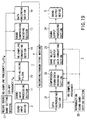
- FIG. 13 is a view illustrating a dot code pattern
format used when recording/printing an encoded sound
file on a sheet of paper as a recording/transmitting
medium;
- FIG. 14 is a view showing the structure of a block
incorporated in the dot code pattern in FIG. 13;
- FIG. 15 is a block diagram showing a compressed-sound-data
decoding section in FIG. 1;
- FIG. 16 is a block diagram showing a band adaptive
type output data converting section in FIG. 1;
- FIG. 17 is a block diagram showing a sound output
processing section in FIG. 1;
- FIG. 18 is a block diagram illustrating an
appropriate band determining/selecting section
incorporated in a third embodiment of the invention;
- FIG. 19 is a block diagram illustrating a digital
sound signal transmitting apparatus and receiving
apparatus according to a fourth embodiment of the
invention;
- FIG. 20 is a view showing a table sheet indicative
of the relationship between a to-be-recorded sound and
a cut-off frequency fw, which are used in the fourth
embodiment;
- FIG. 21 is a block diagram illustrating a digital
sound signal transmitting apparatus and receiving
apparatus according to a fifth embodiment of the
invention;
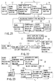
- FIG. 22 is a block diagram illustrating a sound
input processing section in FIG. 21;
- FIG. 23 is a block diagram illustrating a band
adaptive type input data emphasizing/converting
section;
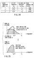
- FIG. 24 is a view of a table showing conditions
for setting a band emphasizing anti-aliasing filter in
FIG. 23; and
- FIG. 25 is a view useful in explaining the
operation of the band emphasizing anti-aliasing filter.
-
-
The embodiments of the invention will be described
with reference to the accompanying drawing.
[First Embodiment]
-
FIG. 1 shows a digital sound signal transmitting
apparatus 1 and receiving apparatus 2 according to a
first embodiment of the invention. The transmitting
apparatus 1 comprises a sound input processing section
11, a band adaptive type input data converting section
12, a sound compression encoding section 13 and a data
recording section 14. The receiving apparatus 2
comprises a data reproducing section 21, a compressed-sound-data
decoding section 22, a band adaptive type
output data converting section 23 and a sound output
processing section 24.
-
In the transmitting apparatus 1, a sound signal
from a sound input device 3 such as a microphone,
an external audio machine, etc. is input to the sound
input processing section 11, where the signal is
digitized. The digitized sound data is input to the
band adaptive type input data converting section 12,
where the band component of the input sound data is
analyzed, i.e. it is analyzed which band component is
contained in the input sound data, thereby determining
a re-sampling frequency on the basis of the analysis
result and re-sampling the input sound data using the
re-sampling frequency. The re-sampling frequency is
also sent to the sound compression encoding section 13
and the data recording section 14, which are located
downstream of the section 12. The re-sampled sound
data is input to the sound compression encoding section
13, where it is subjected to compression encoding in
units of a predetermined number of data samples.
The compression-encoded sound data is input to the
data recording section 14, where it is recorded on
a recording/transmitting medium 4. When the encoded
sound data is recorded, the re-sampling frequency, for
example, is additionally recorded as a header.
-
In the receiving apparatus 2, a data reproducing
section 21 reproduces the encoded sound data recorded
on the recording/transmitting medium 4, and extracts
the re-sampling frequency from the header. The
extracted re-sampling frequency is input to the
compressed-sound-data decoding section 22 and the
band adaptive type output data converting section 23,
which are located downstream of the section 21.
The reproduced encoded sound data is input to the
compressed-sound-data decoding section 22. In the
compressed-sound-data decoding section 22, the input
encoded sound data is decoded by decompression.
The decoded data is input to the band adaptive type
output data converting section 23, where necessary up-sampling
is performed on the basis of the re-sampling
frequency, thereby supplying the resultant sound data
to the sound output processing section 24. The sound
output processing section 24 subjects the input sound
data to D/A conversion, filtering or amplification, and
outputs a sound corresponding to the input sound data
through a sound output device 5 such as a speaker,
an earphone, a headphone, etc.
-
As shown in FIG. 2, the sound input processing
section 11 is constituted of, for example, a pre-amplifier
111, an LPF 112, a sample and hold and A/D
converter (hereinafter referred to as an "S/H & ADC")
113, an input sampling clock generating section 114 and
a sampling frequency converting section 115.
-
An analog sound signal input through the sound
input device 3 is amplified by the pre-amplifier 111.
Then, the frequency component of the amplified signal,
which is not less than a cut-off frequency fs, is cut
off by the LPF 112, and the resultant signal is input
to the S/H & ADC 113. The S/H & ADC 113 is supplied
with a sampling clock signal from the input sampling
clock generating section 114. The S/H & ADC 113
samples an analog sound signal from the LPF 112 on the
basis of the sampling clock signal, and converts the
sampling result to a digital value. The thus-obtained
digital sound data is supplied to the band adaptive
type input data converting section 12.
-
The frequency fa of the sampling clock signal
supplied from the input sampling clock generating
section 114 is set at a value not less than twice the
cut-off frequency fs used in the LPF 112 in order to
satisfy the Nyquist's sampling theorem. The cut-off
frequency fs of the LPF 112 is pre-set as the maximum
frequency of a maximum guarantee band which should be
secured by the transmitting apparatus 1. In the case
of a transmitting apparatus whose target frequency
band is, for example, 8 kHz, 4 kHz or 2 kHz, the cut-off
frequency fs of 8 kHz. Accordingly, the sampling
clock frequency fa is set at 16 kHz or more.
-
Further, where digital sound data is directly
supplied from a digital sound output device 3', as well
as an analog sound signal from the sound input device 3,
the sampling frequency converting section 115 converts
the sampling frequency to a value corresponding to the
transmitting apparatus 1, and supplies the converted
value to the band adaptive type input data converting
section 12. In other words, sampling frequency
conversion is performed when necessary since there are
digital sound output devices 3' in which a rather high
sampling frequency is set.
-
The band adaptive type input data converting
section 12 supplied with digital sound data from the
S/H & ADC 113 and the sampling frequency converting
section 115 comprises, as shown in, for example, FIG. 3,
a frequency band setting section 121, a buffer memory
122, an adaptive anti-aliasing filter 123 and a
re-sampling converting section 124.
-
Digital sound data from the S/H & ADC 113 and
the sampling frequency converting section 115 of the
sound input processing section 11 is supplied to and
stored in the buffer memory 122 and also input to the
frequency band setting section 121. The frequency
band setting section 121 includes a major component
band detecting section 1211 and an appropriate band
determining/selecting section 1212. The input digital
sound data is supplied to the major component band
detecting section 1211, where its major frequency band
is detected, i.e. it is detected in which band the
greatest number of frequency components exist, as will
be described later in detail. The appropriate band
determining/selecting section 1212 determines an
appropriate band on the basis of the detection result,
and sets a cut-off frequency fw and a re-sampling
frequency fv.
-
The cut-off frequency fw is obtained by multiplying,
by an integer, a re-sampling basic frequency f0
which is 1/n (n: integer) of the aforementioned maximum
frequency fs of the maximum guarantee band. The
appropriate band determining/selecting section 1212
stores a plurality of candidate values for the cut-off
frequency obtained by multiplying, by an integer, the
re-sampling basic frequency f0, and sets one of the
candidate values as the cut-off frequency fw on the
basis of the detection result of the major component
band detecting section 1211.
-
In the case where, for example, the maximum
frequency of the maximum guarantee band is 8 kHz, and
the re-sampling basic frequency f0 is 2 kHz which is
1/4 of 8 kHz, the appropriate band determining/selecting
section 1212 stores cut-off frequency
candidates of 2 kHz, 4 kHz, 6 kHz and 8 kHz. If the
major component band detecting section 1211 detects
that the band up to 4 kHz is the major band of the
input digital sound data, and that almost no major
frequency components exist in a frequency band
higher than that, i.e. between 4 kHz and 8 kHz, the
appropriate band determining/selecting section 1212
determines that the band up to 4 kHz is an appropriate
one, and sets the cut-off frequency fw at 4 kHz.
-
Although the re-sampling frequency fv should be
twice or more the cut-off frequency fw, it is set at
twice in this embodiment to minimize the amount of data
processed in such an intermediate processing stage as
above.
-
The set cut-off frequency fw and re-sampling
frequency fv are input to the adaptive anti-aliasing
filter 123 and the re-sampling converting section 124,
respectively. Moreover, as described above, the
re-sampling frequency fv is input to the data recording
section 14 and written into the header section of data.
This frequency fv is also input to the sound compression
encoding section 13 and used to generate a timing
signal corresponding to a process unit for sound
compression encoding performed in a real-time manner.
-
After the cut-off frequency fw and re-sampling
frequency fv are set, the digital sound data stored in
the buffer memory 122 is input to the adaptive anti-aliasing
filter 123, thereby filtering the data using
the cut-off frequency fw so as to prevent reflected
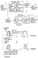
noise. More specifically, as shown in the upper
portion of FIG. 4, the spectrum 61 of an input sound
is filtered by a filter which has an adaptive anti-aliasing
filter characteristic 62 determined based on
the cut-off frequency fw, thereby obtaining sound data
with a spectrum 63 as shown in the lower portion of
FIG. 4.
-
The sound data having passed through the adaptive
anti-aliasing filter 123 is input to the re-sampling
converting section 124, whereby it is again re-sampled
using the re-sampling frequency fv. The re-sampled
data is supplied to the sound compression encoding
section 13.
-
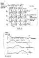
The major component band detecting section 1211
can be formed of, for example, three delay elements
12111A - 12111C, ten adders 12112A - 12112J and six
subtracters 12113A - 12113F, as is shown in FIG. 5.
-
Each of the delay elements 12111A - 12111C delays
the input data by 2D (D = 1/2 fs). Accordingly, the
delay elements 12111A - 12111C provide Xi-2, Xi-4 and
Xi-6 which are obtained by delaying elements in a sound
data string Xi by 2D, 4D and 6D, respectively.
-
The ten adders 12112A - 12112J and the six
12113A - 12113F are constructed to perform the
following matrix calculation (4 × 4 Hadamard
transform):
b0 b1 b2 b3 = 1-1 -1 1 1-1 1 -1 11 1 1 11 -1 -1 xi xi-2 xi-4 xi-6
-
At the stage of 0, Xi from the sound input
processing section 11, Xi-2 from the delay element
12111A, Xi-4 from the delay element 12111B and Xi-6
from the delay element 12111C are multiplied by +1, +1,
+1 and +1, respectively, and then added to each other,
using the four adders 12112A - 12112D. Similarly, at
the stage of 1, Xi, Xi-2, Xi-4 and Xi-6 are multiplied
by -1, -1, +1 and +1, respectively, and then added to
each other, using the subtracters 12113A and 12113B and
the adders 12112E and 12112F. At the stage of 2, Xi,
Xi-2, Xi-4 and Xi-6 are multiplied by -1, +1, +1 and -1,
respectively, and then added to each other, using the
subtracter 12113C, the adders 12112G and 12112H and the
subtracter 12113D. At the stage of 3, Xi, Xi-2, Xi-4
and Xi-6 are multiplied by +1, -1, +1 and -1, respectively,
and then added to each other, using the adder
12112I, the subtracter 12113E, the adder 12112J and the
subtracter 12113F.
-
The thus sequentially obtained real-time outputs
[b0]i - [b3]i of the stages 0 - 3 are supplied to the
appropriate band determining/selecting section 1212.
-
The outputs [b0]i - [b3]i of the stages 0 - 3
indicate frequency components contained in bands, as is
shown in FIG. 6. Specifically, supposing that the
above coefficient +1 indicates a signal wave at the
stage 0, its power spectrum has bands as shown in
the uppermost portion of FIG. 6. In other words, the
output [b0]i of the 0 stage indicates a frequency
component amount which the band 0 - f0 (= fs/4) mainly
contains. Similarly, the output [b1]i of the 1 stage
indicates a major frequency component amount in the
band f0 - f1 (= 2f0 = fs/2), the output [b2]i of the
2 stage a major frequency component amount in the
band f1 - f2 (= 3f0 = 3fs/4), and the output [b3]i of
the 3 stage a major frequency component amount in the
band f2 - fs (= 4f0).
-
The major component band detecting section 1211
is not limited to a structure as described above for
performing Hadamard transform, but may have any
structure which realizes orthogonal transform suitable
for frequency analysis, such as discrete Fourier
transform, discrete cosine transform, etc.
-
Also, the appropriate band determining/selecting
section 1212 which receives the outputs [b0]i - [b3]i
of the major component band detecting section 1211
comprises three adders 12121A - 12121C, four
normalizing sections 12122A - 12122D, three subtracters
12123A - 12123C, three summing-up sections 12124A -
12124C, a maximum value detecting section 12125 and
a cut-off frequency and re-sampling frequency setting
section 12126.
-
The three adders 12121A - 12121C add up the
outputs [b0]i - [b3]i which indicate the above
component amounts in the divided bands, and supply the
sum as b to the four normalizing sections 12122A -
12122D. Further, [b0]i - [b3]i are input to the
normalizing sections 12122A - 12122D, respectively.
The normalizing sections 12122A - 12122D then divide
the supplied [b0]i - [b3]i by the addition result b,
and obtain the absolute values of the division results.
In other words, the ratio of the component amount
of each divided band to that of the entire band is
obtained.
-
The difference between the outputs of each
adjacent pair of the normalizing sections 12122A -
12122D corresponding to adjacent bands is calculated
using the three subtracters 12123A - 12123C.
The outputs [c1]i - [c3]i of the subtracters
12123A - 12123C are supplied to the summing-up sections
12124A - 12124C, respectively. c1 - c3 are sequentially
output in units of one sampling operation, and
added up by the summing-up sections 12124A - 12124C.
In this case, i assumes a value falling within a range
of from jL to {i + (L - 1)}, where j represents any
integer falling within a range of from 0 to a value
which is obtained by dividing, by L, the total number
of input sound samples during sampling using the
frequency fa (L: the number of samples expressed by
t0/(1/fa)). Further, t0 is expressed by N(1/2f0)
(N: the number of process unit samples in each
compression-encoding frame).
-
More specifically, the number N of process unit
samples in each compression-encoding frame is an
automatically determined value, such as 240 samples,
after compression encoding algorithm is determined.
After the sample number N is determined, the process
time required for each frame varies. In other words,
since the number of data items is constant and the
sampling frequency varies, the unit process time varies
A unit process time t0 at the minimum sampling
frequency f0 of the guarantee band is obtained by
multiplying a sample number N, e.g. 240, by a cycle
(= 1/2f0). Similarly, a unit process time ts at the
maximum sampling frequency fs of the guarantee band is
N(1/2fs).
-
The unit process time varies depending upon the
band as shown in FIG. 8. The frequency component is
determined on the basis of a longest unit process time.
Specifically, bands included within a unit process
time required in each compression-encoding frame are
detected, and an appropriate re-sampling frequency and
cut-off frequency are determined on the basis of the
detection result. Since, however, the unit process
time in each compression-encoding frame is determined
for the first time after the re-sampling frequency and
cut-off frequency are determined, it is necessary to
set a temporal unit process time to perform such
processing. In this embodiment, the longest unit
process time t0 is set as a time zone for determining
the frequency component.
-
Supposing that the maximum sampling frequency fs
of the guarantee band, the re-sampling basic frequency
f0 and the value N (samples in each compression-encoding
frame) are set at 8 kHz, 2 kHz and 240,
respectively, the following values are obtained:
ts = N((1/2)fs) = 240(1/2 × 8000) = 0.015 = 15(msec.) t2 = N((1/2)f2) = 240(1/2 × 6000) = 0.02 = 20(msec.) t1 = N((1/2)f1) = 240(1/2 × 4000) = 0.03 = 30(msec.) t0 = N((1/2)f0) = 240(1/2 × 2000) = 0.06 = 60(msec.)
-
Thus, the summing-up sections 12124A - 12124C sum
up the outputs [c1]i - [c3]i of the subtracters
12123A - 12123C, respectively, for each time zone
of the longest process unit time t0 which includes
a number L of samples, thereby inputting the resultant
values [c1]j - [c3]j to the maximum value detecting
section 12125. The maximum value detecting section
12125 detects a maximum value in each zone which
includes the number L of samples, thereby determining
which frequency component is maximum in amount.
An appropriate band number k as an ID number indicative
of a frequency band corresponding to the maximum value
is input from the maximum value detecting section 12125
to the cut-off frequency and re-sampling frequency
setting section 12126. The cut-off frequency and
re-sampling frequency setting section 12126 has a table
for setting the cut-off frequency and the re-sampling
frequency as shown in FIG. 9, and is adapted to output
a cut-off frequency fw and re-sampling frequency fv
corresponding to the appropriate band number k as
a result of reference to the setting table.
-
FIG. 10 shows the relationship between the
waveform of an input sound and the encoding frame,
which is obtained after adaptive band conversion is
performed in the re-sampling converting section 124 of
FIG. 3. In the re-sampling converting section 124,
sound data from the adaptive anti-aliasing filter 123
is re-sampled in accordance with the re-sampling
frequency fv (i.e. at a cycle of 1/fv) supplied from
the cut-off frequency and re-sampling frequency setting
section 12126 of the appropriate band
determining/selecting section 1212, thereby obtaining
sampling values X'0, X'1, ..., X'N.
-
The sound compression encoding section 13, which
receives the re-sampled sound data and the re-sampling
frequency fv, comprises a process timing clock
converting section 131, an analysis/synthesis encoding
section (or waveform encoding section) 132 and a sound
frame buffer 133 as shown in FIG. 11.
-
The re-sampling frequency fv determined by the
cut-off frequency and re-sampling frequency setting
section 12126 of the appropriate band determining/selecting
section 1212 is input to the process timing
clock converting section 131. The process timing clock
converting section 131 generates a clock signal CLK
indicative of a process time point in each frame by
dividing the re-sampling frequency fv by the number of
samples included in each frame, and supplies the signal
CLK to the analysis/synthesis encoding section 132.
On the other hand, sound data d re-sampled in the
re-sampling converting section 124 is once stored in
the sound frame buffer 133. The analysis/synthesis
encoding section 132 responds to the clock signal CLK
to thereby sequentially read sound data df for each
encoding frame from the sound frame buffer 133, encode
it and output the resultant data as encoded data to the
data recording section 14 of the next stage.
-
Supposing that the process unit is set at 240
samples, the time required for completing processing in
each frame is 60 msec. for 4 kHz sampling, 30 msec. for
8 kHz sampling, and 15 msec. for 16 kHz sampling.
-
The structure of the sound compression encoding
section 13 is for performing real-time processing.
Where re-sampled sound data is stored in, for example,
a memory, read when necessary therefrom and subjected
to analysis/synthesis encoding, no clock signal CLK is
necessary since it is not always necessary to perform
processing in units of one sound encoding frame and in
a real-time manner.
-
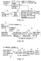
The data recording section 14 records, in the
recording/transmitting medium 4, an encoded sound file
which is obtained by attaching a header to encoded data
from the analysis/synthesis encoding section 132.
FIG. 12 shows an example of a data structure of the
encoded sound file. As shown, an encoded sound file
141 comprises a re-sampling frequency value 1411 as
a header, an encoding condition parameter 1412 and
encoded data 1413. The re-sampling frequency value
1411 indicates a re-sampling frequency fv from the cut-off
frequency and re-sampling frequency setting section
12126. The encoding condition parameter 1412 is data
indicative of various parameters used for encoding
including compression.
-
Since the re-sampling frequency fv is known to be
twice the cut-off frequency fw, the encoded sound file
141 may include the cut-off frequency in place of the
re-sampling frequency, or both the cut-off frequency
and the re-sampling frequency.
-
Further, various conventional methods can be
employed as methods for recording or transmitting the
encoded sound file 141 into the recording/transmitting
medium 4. For example, as is disclosed in EP 0,670,555
A1 filed by the assignee of the present invention,
information such as sound information can be recorded
by printing in the form of an optically readable dot
code on the recording/transmitting medium 4 such as
a paper sheet.
-
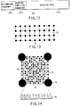
As is illustrated in FIG. 13, the dot code denoted
by reference numeral 71 comprises a block group which
includes blocks 72 including a predetermined number
of dots and arranged in a two-dimensional matrix.
Each block 72 which includes a predetermined number of
dots is recognized to have a predetermined density in
a broad view.
-
FIG. 14 is an enlarged view of one of the blocks
which constitute the dot code 71. As shown, the block
72 includes a data dot pattern section 73 which is
obtained by modulating the data of the encoded sound
file 141 such that pieces of the data are arranged in
accordance with their bit values; and a block header
section 74 indicative of information such as the
address of the block 72 and disposed in a predetermined
positional relationship with respect to the data dot
pattern section 73. The block 72 further includes
markers 75 situated at predetermined locations, for
example, at its four corners, for recognizing the block
72; and a matching dot pattern 76 provided between
adjacent ones of the markers 75 in a first direction.
The block header section 74 is situated between
adjacent ones of the markers 75 in a second direction.
The dots provided in the block header section 74 and
the matching dot pattern 76 have the same size as those
(hereinafter referred to as "data dots") provided in
the data dot pattern section 73. The data dots have a
size of, for example, 40 - 80 µm. Further, the markers
75 have a greater size than the data dots, and are
recorded, on a recording medium, as circular dots
having a diameter, for example, five times that of the
data dots.
-
The data of the encoded sound file 141 is
modulated into a data dot pattern before being recorded.
The modulation is performed to limit the number of data
dots continuously arranged in order to discriminate the
data dots from the markers 75. For example, when the
diameter of the marker 75 is five time that of the data
dot, the number of continuously arranged data dots must
be limited to 4 or less.
-
Although FIG. 14 shows a block 72 including (17 ×
17) data dots, the block 72 is not limited to this size,
but may include (30 × 30) or (40 × 40) data dots.
It should be noted that the lines which are arranged in
the form of a grid are imaginary ones.
-
Further, although an apparatus for printing/recording
such a dot code 71 is described in detail in
the aforementioned publication EP 0,670,555 A1 and
therefore will not be explained, it is applicable to
the data recording section 14.
-
As is shown in FIG. 1, the receiving apparatus 2
reproduces, using the data reproducing section 21,
the encoded sound file data recorded on or in the
recording/transmitting medium 4. When using the above-described
dot code 71, a reproducing apparatus also
described in detail in the publication EP 0,670,555 A1
can be sued as the data reproducing section 21.
-
The data reproducing section 21 reproduces the
encoded sound file data as described above, and also
extracts a re-sampling frequency from the header
section of the file. Then, it inputs the extracted
re-sampling frequency fv to the compressed-sound-data
decoding section 22 and the band adaptive type output
data converting section 23, and also generates a
cut-off frequency fw which is half the re-sampling
frequency fv, thereby inputting it to the band adaptive
type output data converting section 23. Further, the
encoded sound data represented by the data reproducing
section 21 is supplied to the compressed-sound-data
decoding section 22.
-
The compressed-sound-data decoding section 22
comprises a process timing clock generating section 221,
an analysis/synthesis encoded data decoding section
(or a waveform encoded data decoding section) 222, and
a sound frame buffer 223 as shown in FIG. 15.
-
In the compressed-sound-data decoding section 22,
the re-sampling frequency fv extracted in the data
reproducing section 21 is fed to the process timing
clock generating section 221. The process timing
clock generating section 221 divides the re-sampling
frequency fv by the number of process unit samples
to thereby determine the frequency of a clock signal
indicative of a time point of processing in each
encoding frame. The section 221 then creates a clock
signal CLK of the determined frequency and feeds it to
the analysis/synthesis encoded data decoding section
222. On the other hand, data df reproduced by the data
reproducing section 21 is once input to and stored in
the sound frame buffer 223. The analysis/synthesis
encoded data decoding section 222 responds to the clock
signal CLK to thereby sequentially read data from the
sound frame buffer 223 in units of one encoding frame,
and then decode it, thereby outputting resultant data
as decoded data d to the band adaptive type output data
converting section 23 of the next stage.
-
The structure of the above compressed-sound-data
decoding section 22 is for performing real-time
processing. Where re-sampled sound data is stored in,
for example, a memory, read when necessary therefrom
and subjected to analysis/synthesis encoding/decoding
processing, no clock signal CLK is necessary since it
is not always necessary to perform processing in units
of one sound encoding frame and in a real-time manner.
-
FIG. 16 shows the structure of the band adaptive
type output data converting section 23. This section
comprises an up-sampling converting section 231 and
an adaptive digital low-pass filter 232.
-
The re-sampling frequency fv and the cut-off
frequency fw from the data reproducing section 21 are
fed to the up-sampling converting section 231 and the
adaptive digital low-pass filter 232, respectively.
The up-sampling converting section 231 performs
up-sampling of the decoded data d output from the
compressed-sound-data decoding section 22, using a high
frequency fu which is, for example, four times the
re-sampling frequency fv. The up-sampling frequency fu
is fed to the sound output processing section 24 of
a post stage. The up-sampled data du is subjected to
the adaptive digital low-pass filter 232, where a
frequency component higher than the cut-off frequency
fw is cut off the data. The resultant data is fed to
the sound output processing section 24.
-
The sound output processing section 24 comprises
an S/H & ADC 241, an LPF 242 and a pre-power-amplifier
243 as shown in FIG. 17.
-
In the sound output processing section 24, the
up-sampling frequency fu from the up-sampling
converting section 231 of the band adaptive type output
data converting section 23 is input to the S/H & ADC
241, where data do from the adaptive digital low-pass
filter 232 of the band adaptive type output data
converting section 23 is sampled and held using the
up-sampling frequency fu, and subjected to D/A
conversion. The signal, which has been converted to
an analog signal as a result of up-sampling by the
up-sampling converting section 231, is then subjected
to the LPF 242 where its high frequency component is
cut. Although in this case, the LPF 242 employs the
cut-off frequency fw, its cut-off characteristic may be
gentle since pre-filtering is performed in the adaptive
digital low-pass filter 232. The output of the LPF 242
is input as an analog sound signal to the pre-power-amplifier
243, amplified by it, then input to and
output as an actual sound from the sound output device
5 such as a speaker.
-
As described above, in the transmitting apparatus
1 of the first embodiment, the frequency band setting
section 121 sets the frequency band of a digital sound
signal to be transmitted, and determines the cut-off
frequency and re-sampling frequency of the digital
sound signal on the basis of the set frequency band;
the adaptive anti-aliasing filter 123 adaptively
filters the to-be-transmitted digital sound signal on
the basis of the cut-off frequency; the re-sampling
converting section 124 re-samples the digital sound
signal having passed through the filter 123, using
the determined re-sampling frequency; and the sound
compression encoding section 13 subjects the re-sampled
digital sound signal to compression encoding in units
of a predetermined number of data samples, to thereby
generate encoded data. Then, the data recording
section 14 records, as an encoded sound file 141 on the
recording/transmitting medium 4, the encoded data 1413
and control data, such as the re-sampling frequency
1411, which relates to the cut-off frequency and/or
re-sampling frequency determined by the frequency band
setting section 121. Thus, the encoded sound file 141
is transmitted to the receiving apparatus 2 via the
recording/transmitting medium 4.
-
In the digital sound signal receiving apparatus 2
for receiving the encoded sound file 141 output from
the transmitting apparatus 1 constructed as above,
the data reproducing section 21 extracts the cut-off
frequency and/or the re-sampling frequency determined
by the frequency band setting section 121, using the
re-sampling frequency 1411 contained in the encoded
sound file 141 transmitted via the recording/transmitting
medium 4; and the compressed-sound-data
decoding section 22 performs decompression decoding
corresponding to the compression encoding processing,
using the extracted cut-off frequency and/or
re-sampling frequency.
-
Since in the above-described transmitting
apparatus 1, a sound signal has its sound quality
(sound band) adaptively limited by the adaptive
anti-aliasing filter 123, and the resultant sound
signal is sampled using a necessary sampling frequency,
and encoded by the single sound compression encoding
section 13, the amount of data can be controlled so as
to realize sound quality sufficient to satisfy various
purposes, which means that generation of an unnecessary
amount of data can be avoided. Further, since the data
amount can be controlled using a single compression
encoding system, the transmitting apparatus can be made
at low cost and simple in structure. Also, in the
embodiment, the transmitting apparatus 1 transmits both
the encoded data and control data relating to the cut-off
frequency and/or the re-sampling frequency, while
the receiving apparatus 2 extracts the control data
to thereby reliably obtain the cut-off frequency/re-sampling
frequency used to generate individual encoded
data items. Accordingly, each encoded data item can be
converted to a sound signal.
[Second Embodiment]
-
A second embodiment of the invention will be
described. In the first embodiment, an adaptive band
is determined for each encoded sound data item, whereas
in the second embodiment, it is determined for each
input sound data item.
-
To realize this, it is necessary to change the
structure of the adaptive band determining/selecting
section 1212 shown in FIG. 7 such that the summing-up
sections 12124A - 12124C perform their calculation from
i = 0 to i = M instead of from i = jL to i = i + (L-1),
and the outputs c1 - c3 of the sections 12124A - 12124C
are supplied to the maximum value detecting section
12125. M represents a positive integer such as 0,
1, ..., and indicates the total number of input sound
samples.
-
In other words, in the second embodiment, a single
re-sampling frequency and cut-off frequency are
determined from the entire input sound.
[Third Embodiment]
-
A third embodiment of the invention will be
described. As shown in FIG. 18, in the third
embodiment, the outputs c1 - c3 of summing-up sections
12124A' - 12124C' included in an adaptive band
determining /selecting section 1212 similar to that of
the second embodiment are supplied to a neural network
determining section 12127 instead of the maximum value
detecting section 12125.
-
When determining, using the ears of individuals,
which band component is a major component, it is
difficult to uniformly set the cut-off frequency at,
for example, 6 kHz since such determination is based on
their subjectivity and hence different determination
results will be obtained between them. In light of
this, in the third embodiment, various sounds which
each contain a major component of a certain band and
minor components of other bands are filtered using
different cut-off frequencies, and the resultant sounds
are actually listened to and compared with each other,
thereby causing, for example, a neural network to learn
cut-off frequencies which can produce preferable sounds.
Thus, it can be determined which cut-off frequency
should be used when a sound pattern of a band
combination is input.
[Fourth Embodiment]
-
A fourth embodiment of the invention will be
described. In this embodiment, the appropriate band is
not automatically but manually set.
-
FIG. 19 shows the structure of the fourth
embodiment. In FIG. 19, elements similar to those of
the first embodiment shown in FIG. 1 are denoted by
corresponding reference numerals. In this embodiment,
the transmitting apparatus 1 comprises an anti-aliasing
filter 15 and a re-sampling converting section 16
instead of the band adaptive type input data converting
section 12 of the first embodiment, and also a record
sound band setting section 17. Further, the receiving
apparatus 2 comprises a band select type output data
converting section 25 instead of the band adaptive
type output data converting section 23 of the first
embodiment, and if necessary, a reproduction sound band
setting section 26.
-
More specifically, in the transmitting apparatus 1
of the fourth embodiment, a sound signal from the sound
input device 3 is converted to digital data by the
sound input processing section 11 as described above,
and then input to the anti-aliasing filter 15.
Although the anti-aliasing filter 15 has the same
function as the adaptive anti-aliasing filter 123 of
the first embodiment, the cut-off frequency fw of the
filter 15 is set by the user via the record sound band
setting section 17.
-
The record sound band setting section 17 includes
a switch for permitting the user to optionally set one
of a plurality of cut-off frequencies fw, and is
arranged to supply the anti-aliasing filter 15 with the
set cut-off frequency fw and supply the re-sampling
converting section 16, the sound compression encoding
section 14 and the data recording section 14 with a
re-sampling frequency fv which is twice the set cut-off
frequency fw.
-
It is preferable to prepare a table sheet 8, as
shown in FIG. 20, which indicates the relationship
between a to-be-recorded sound and the cut-off
frequency fw and is used as an auxiliary member for
permitting the user to select a desired cut-off
frequency fw through the record sound band setting
section 17. The table sheet 8 enables the user to
easily know from the type of a to-be-recorded sound
which cut-off frequency fw should be set. It is a
matter of course that a table as described in the table
sheet 8 may be set in the record sound band setting
section 17 so that the user can select and set a sound
type to thereby automatically set a cut-off frequency
fw corresponding thereto.
-
Sound data whose reflected noise is removed by the
anti-aliasing filter 15 is input to the re-sampling
converting section 16 which corresponds to the re-sampling
converting section 124 of the first embodiment,
where the data is re-sampled using the re-sampling
frequency fv set by the record sound band setting
section 17. The re-sampled sound data is input to the
sound compression encoding section 13, where it is
subjected to compression encoding in units of a
predetermined number of data samples. The compression
encoded data is input to the data recording section 14,
where it is recorded as the encoded sound file 141 on
the recording/transmitting medium 4. The encoded sound
file 141 includes the re-sampling frequency 1411 as
a header as in the first embodiment.
-
On the other hand, in the receiving apparatus 2,
the data reproducing section 21 reproduces the encoded
sound file recorded on the recording/transmitting
medium 4, and also extracts the re-sampling frequency
from the header section. The extracted re-sampling
frequency is input to the compressed-sound-data
decoding section 22 and the band select type output
data converting section 25, while the reproduced
encoded sound data is input to the compressed-sound-data
decoding section 22. The section 22 decodes the
input encoded sound data and input the decoded sound
data to the band select type output data converting
section 25. The section 25 corresponds to the band
adaptive type output data converting section 23 of the
first embodiment, and is arranged to perform necessary
up-sampling on the basis of the re-sampling frequency
selected by the user and output from the data
reproducing section 21, thereby inputting the resultant
sound data to the sound output processing section 24.
The section 24 performs D/A conversion, filtering,
amplification, etc., and outputs a sound corresponding
to the input sound data through the sound output device
5 such as a speaker, an earphone, a headphone, etc.
-
Instead of the re-sampling frequency extracted
in the data reproducing section 21, a re-sampling
frequency set in the reproduction sound band setting
section 26 may be supplied to the compressed-sound-data
decoding section 22 and the band select type output
data converting section 25 as indicated by the broken
lines in FIG. 19. In this case, the reproduction sound
band setting section 26 includes, for example, a switch
for permitting the user to optionally set one of a
plurality of re-sampling frequencies fv as in the case
of the record sound band setting section 17 of the
transmitting apparatus 1, and also includes a display
section for displaying the re-sampling frequency
supplied from the data reproducing section 21.
When the user has selected and set the re-sampling
frequency fv using the switch while observing the
display section, the re-sampling frequency is supplied
to the compressed-sound-data decoding section 22 and
the band select type output data converting section 25.
[Fifth Embodiment]
-
A fifth embodiment of the invention will be
described. This embodiment is applied to a case where
the determined appropriate band cannot be used in light
of its data amount. In this embodiment, a band lower
than the appropriate band is employed and a high
frequency area of the band is emphasized.
-
FIG. 21 illustrates the structure of the fifth
embodiment, in which elements similar to those of
the first embodiment shown in FIG. 1 are denoted by
corresponding reference numerals. In this embodiment,
the transmitting apparatus 1 comprises a sound input
processing section 11' and a band adaptive type input
data emphasizing/converting section 18, which are used
instead of the sound input processing section 11 and
the band adaptive type input data converting section 12,
respectively. Further, in the receiving apparatus 2,
the band adaptive type output data converting section
23 is not employed, and the output of the compressed-sound-data
decoding section 22 is directly supplied to
the sound output processing section 24.
-
As is understood from FIG. 22, the sound input
processing section 11' is obtained by removing the
sampling frequency converting section from the voice
input processing section 11 shown in FIG. 2.
-
Further, as shown in FIG. 23, the band adaptive
type input data emphasizing/converting section 18
includes a major component band detecting section 181,
an appropriate band determining/selecting section 182,
a band emphasizing anti-aliasing filter 183, a buffer
memory 184 and a re-sampling converting section 185.
More specifically, digital sound data from the sound
input processing section 11' is supplied to and stored
in the buffer memory 184 corresponding to the buffer
memory 122 of the first embodiment, and also supplied
to the major component band detecting section 181
corresponding to the major component band detecting
section 1211 of the first embodiment. The major
component band detecting section 181 detects the major
frequency band of the input digital sound data, and
supplies the detection result to the appropriate band
determining/selecting section 182. The section 182 has
a structure obtained by removing the cut-off frequency
and re-sampling frequency setting section 12126 from
the appropriate band determining/selecting section 1212
shown in FIG. 7. Accordingly, in this embodiment,
an appropriate band ID output from the maximum value
detecting section 12125 is supplied as a major
component band ID to the band emphasizing anti-aliasing
filter 183.
-
The band emphasizing anti-aliasing filter 183 has
a setting condition table as shown in FIG. 24, and is
arranged to refer to the setting table on the basis of
the major component band ID output from the appropriate
band determining/selecting section 182, thereby
determining the cut-off frequency fw, the re-sampling
frequency fv, and whether or not there is a band
emphasizing filter, and supplying the re-sampling
frequency fv to the re-sampling converting section 185,
and also to the sound compression encoding section 13
and data recording section 14 which are located
downstream of the band adaptive type input data
emphasizing/converting section 18. Then, digital sound
data stored in the buffer memory 184 is read, and the
spectrum 61 of the input sound corresponding to the
sound data is filtered by a filter which has a band
emphasizing anti-aliasing filter characteristic 64
based on the cut-off frequency fw, as is shown in the
upper portion of FIG. 25. After this band emphasizing
processing, sound data having a spectrum 65 is obtained,
as is shown in the lower portion of FIG. 25.
-
The sound data obtained through the band
emphasizing anti-aliasing filter 183 is input to a
re-sampling converting section 185 corresponding to
the re-sampling converting section 124 of the first
embodiment, then again re-sampled using the re-sampling
frequency fv, and supplied to the sound compression
encoding section 13.
-
The invention is not limited to the above-described
embodiments, but may be modified in various
manners without departing from its scope. In summary,
the invention can provide an apparatus as described
below.
- (1) A digital sound signal transmitting apparatus
(1) for compression encoding a digitized sound signal
into encoded data, and transmitting the encoded data
via a predetermined medium (4), comprising:
- a frequency band setting unit (121; 17; 18) for
setting a frequency band for a to-be-transmitted
digital sound signal, and determining a cut-off
frequency (fw) and a re-sampling frequency (fv) for the
digital sound signal on the basis of the set frequency
band;
- an adaptive band limiting filter (123; 15; 183)
for adaptively filtering the to-be-transmitted digital
sound signal on the basis of the cut-off frequency
(fv) determined by the frequency band setting unit
(121; 17; 18);
- a re-sampling unit (124; 16; 185) for re-sampling
the digital sound signal having passed through the
adaptive band limiting filter (123; 15; 183), using the
re-sampling frequency (fv) determined by the frequency
band setting unit (121; 17; 18); and
- a compression encoding unit (13) for compression
encoding the digital sound signal re-sampled by the
re-sampling unit (124; 16; 185), in units of a predetermined
number of data samples, thereby creating
encoded data.
When subjecting a sound signal to real-time
processing and then recording or transmitting it,
there is a basic demand to minimize the amount of
data in order to minimize the transmission load on
the transmission channel, and also to transmit sound
signals of quality appropriate for purposes. The data
amount and the sound quality have a "trade-off"
relationship. To minimize the data amount and to
secure a sound band which is one of important factors
for obtaining a high quality sound, compression
encoding is generally performed. To perform the
compression encoding, a plurality of encoding methods
using a predetermined compression ratio are usually
prepared and selectively used.On the other hand, in the structure described in
item (1), the sound quality (sound band) is adaptively
limited by an adaptive band limiting filter, then
re-sampled using a necessary re-sampling frequency,
and encoded by single compression encoding unit.
Accordingly, data amount control can be realized which
enables sufficient expression of high quality sounds
requested for various purposes, thereby preventing
generation of an unnecessary amount of data. Moreover,
the data amount control is realized using a single
compression encoding method, with the result that a
transmitting apparatus can have a simple structure and
can be made at a low cost. - (2) The digital sound signal transmitting
apparatus according to item (1), wherein when the
predetermined number of data samples is N and the
re-sampling frequency (fv) is f, the compression
encoding unit (13) performs compression encoding on the
predetermined number N of data samples in units of a
time period T, where the equation N = Tf is satisfied.
Where re-sampling is performed using a re-sampling
frequency f, a number N of data samples, which number
is a processing unit of compression encoding, can be
processed in units of a time period T where N = Tf is
satisfied. Therefore, real-time processing can be
performed without any extra buffer memory for time
adjustment.
- (3) The digital sound signal transmitting
apparatus according to item (1), wherein the
compression encoding unit (13) always performs
compression encoding in units of a minimum value of
the time period T which the compression encoding unit
(13) can assume, irrespective of the re-sampling
frequency (fv).
The fact that the compression encoding is
performed in units of a minimum time period T means
that real-time processing can be performed on data
re-sampled using a maximum re-sampling frequency.
In other words, real-time processing can be always
performed on any data re-sampled using a re-sampling
frequency which is lower than the maximum one.
Therefore, real-time processing can be performed
without any extra buffer memory for time adjustment.
- (4) The digital sound signal transmitting
apparatus according to item (1), wherein control data
(1411) related to the cut-off frequency (fw) and/or the
re-sampling frequency (fv) determined by the frequency
band setting unit (121, 17, 18) is transmitted through
the predetermined medium (4), together with the encoded
data (1413).
The cut-off frequency and/or the re-sampling
frequency having used for the generation of the encoded
data can be individually informed of in a reliable
manner as a result of the transmission of control data
related to the cut-off frequency and/or the re-sampling
frequency, together with encoded data. Accordingly,
decoded data can be converted to a sound signal without
errors.
- (5) The digital sound signal transmitting
apparatus according to item (1), wherein the frequency
band setting unit (17) includes an operation unit (17)
to be operated by a user so as to select one of a
plurality of frequency bands.
Since the user can select a guarantee frequency
band contained in a to-be-transmitted sound signal,
they can select one of a plurality of frequency bands
from their own judgment in hearing. This means that
the user can control sound quality and hence optionally
and flexibly select an optimal frequency band.
- (6) The digital sound signal transmitting
apparatus according to item (1), wherein the frequency
band setting unit (121; 18) includes an automatic
frequency band detecting unit (1211, 1212; 181, 182,
183) for detecting, from a to-be-transmitted digital
sound signal, a frequency band contained in the digital
sound signal, and determining the cut-off frequency
(fw) and the re-sampling frequency (fv) on the basis of
the detected frequency band.
The automatic frequency band detecting unit, which
automatically selects an appropriate frequency band
for a sound signal, enables the user to confirm an
appropriate frequency band for an individual sound
signal, to save time and labor for selecting the
appropriate frequency band and to perform easy and
short-time operation.
- (7) The digital sound signal transmitting
apparatus according to item (1), wherein:
- the frequency band setting unit (121; 18) includes
an automatic frequency band detecting unit (1211, 1212;
181, 182, 183) for detecting, from a to-be-transmitted
digital sound signal, a frequency band contained in
the digital sound signal, and determining the cut-off
frequency (fw) and the re-sampling frequency (fv) on
the basis of the detected frequency band;
- the compression encoding unit (13) performs, when
the predetermined number of data samples is N and the
re-sampling frequency (fv) is f, compression encoding
of the predetermined number N of data samples in units
of a time period T, where the equation N = Tf is
satisfied; and
- the automatic frequency band detecting unit (1211,
1212; 181, 182, 183) detects the frequency band of the
to-be-transmitted digital sound signal in units of
a maximum value of the time period T which the
compression encoding unit (13) can assume.
Although there is a case where a necessary
guarantee frequency band is set for the entire sound
signal, to control, when necessary, the guarantee
frequency band for individual local portions of the
sound signal is very advantageous in order to save the
data amount of the entire sound signal and secure sound
quality, since lots of sound signals exist which each
contain different frequency components.Since in the structure described in item (7),
sound data is processed in units of a predetermined
encoding frame, the re-sampling frequency can be
changed in units of the encoding frame. When the
guarantee frequency band to be selected in units of the
encoding frame is changed, the tine of the encoding
frame itself changes. However, which guarantee
frequency band should be selected is not known before
it is detected. Accordingly, the detection period of
the to-be-selected guarantee frequency band must be at
least kept unchanged irrespective of the encoding frame
which will change after the detection of the guarantee
frequency band.When the frequency band of a sound signal is
automatically detected in units of a maximum process
unit time period which the compression encoding unit
can assume, and an appropriate re-sampling frequency
based on the detected frequency band is used, the
re-sampling frequency can be changed in a consistent
and flexible manner for a process unit time period less
than the maximum one. As a result, the guarantee
frequency band of the sound signal can be controlled in
units of a shorter process unit time period, and hence
sound quality can be secured using an optimal amount of
data. - (8) The digital sound signal transmitting
apparatus according to item (1), wherein the adaptive
band limiting filter (183) also serves as a band
emphasizing filter for emphasizing a predetermined
frequency band contained in the to-be-transmitted
digital sound signal.
Since the adaptive band limiting filter also
serves as a band emphasizing filter for emphasizing
a predetermined frequency band, even a sound signal
containing a frequency component which exceeds the set
frequency band can be aurally compensated without
changing the band.
- (9) The digital sound signal transmitting
apparatus according to item (1), wherein the apparatus
is an encoded-image recording apparatus for transmitting
a digital sound signal by recording, by printing,
the signal as an optically readable encoded image (71)
on a predetermined printing medium as the predetermined
medium (4).
In the above structure, sound information is
transmitted as a result of being recorded on a printing
medium as an optically readable encoded image, which
could not be realized by any conventional printing
medium. Thus, the invention can provide cheap and
easy-to-handle visual, aural information, in addition
to conventional visual information such as images or
characters.
- (10) A digital sound signal receiving apparatus
(2) for receiving data which contains encoded data
transmitted from a digital sound signal transmitting
apparatus including: a frequency band setting unit
(121; 17; 18) for setting a frequency band for a to-be-transmitted
digital sound signal, and determining a
cut-off frequency (fw) and a re-sampling frequency (fv)
for the digital sound signal on the basis of the set
frequency band; an adaptive band limiting filter (123;
15; 183) for adaptively filtering the to-be-transmitted
digital sound signal on the basis of the cut-off
frequency (fv) determined by the frequency band setting
unit (121; 17; 18); a re-sampling unit (124; 16; 185)
for re-sampling the digital sound signal having passed
through the adaptive band limiting filter (123; 15;
183), using the re-sampling frequency (fv) determined
by the frequency band setting unit (121; 17; 18); and a
compression encoding unit (13) for compression encoding
the digital sound signal re-sampled by the re-sampling
unit (124; 16; 185), in units of a predetermined number
of data samples, thereby creating encoded data,
- the receiving apparatus comprising:
- an input designating unit (21; 21, 26) for
designating input of the cut-off frequency (fw) and/or
the resampling frequency (fv) determined by the
frequency band setting unit (121; 17; 18); and
- a decompression decoding unit (22) for performing
decompression decoding corresponding to the compression
encoding on the basis of the cut-off frequency (fw)
and/or the re-sampling frequency (fv) designated by the
input designating unit (21; 21, 26).
In the transmitting apparatus, a sound signal has
its sound quality (sound band) adaptively limited by
the adaptive band limiting filter, and is sampled using
a necessary sampling frequency and encoded by single
encoding unit. As a result, the data amount is
controlled to a value which is sufficient to express a
sound of quality required for a purpose. On the other
hand, when receiving the encoded sound data, the user
of the receiving apparatus can input the cut-off
frequency and/or the re-sampling frequency determined
when the sound is encoded and necessary to reproduce
the sound. This means that the reproducing condition
can be set in a reliable manner, and hence that the
encoded data can be decoded and reproduced without
errors. Thus, the invention can realize transmission
of a sound signal with its data amount controlled (i.e.
without generating an extra amount of data), using
a single compression encoding method. This enables
simplification of the structure of the apparatus and
reduction of its manufacturing cost. - (11) The digital sound signal receiving apparatus
according to item (10), wherein:
- when the predetermined number of data samples is
N and the re-sampling frequency (fv) is f, the
compression encoding unit (13) performs compression
encoding of the predetermined number N of data samples
in units of a time period T, where the equation N = Tf
is satisfied; and
- the decompression decoding unit (22) performs
decompression decoding in units of the time period T.
Where re-sampling is performed using a re-sampling
frequency f, a number N of data samples, which number
is a processing unit of compression encoding, can be
processed in units of a time period T where N = Tf is
satisfied. Therefore, real-time processing can be
performed without any extra buffer memory for time
adjustment. - (12) The digital sound signal receiving apparatus
according to item (11), wherein:
- the compression encoding unit (13) always performs
compression encoding in units of a minimum value of the
time period T which the compression encoding unit (13)
can assume, irrespective of the re-sampling frequency
(fv); and
- the decompression decoding unit (22) always
performs the decompression decoding in units of the
minimum value of the time period T.
The fact that the compression encoding is
performed in units of a minimum time period T means
that real-time processing can be performed on data
re-sampled using a maximum re-sampling frequency.
In other words, real-time processing can be always
performed on any data re-sampled using a re-sampling
frequency which is lower than the maximum one. Further,
decompression decoding of the encoded data in units of
the minimum time period T enables real-time processing
of data re-sampled using any re-sampling frequency.
Therefore, real-time processing can be performed
without any extra buffer memory for time adjustment.
Further, since it is not necessary to control the
process time in accordance with the re-sampling
frequency, decoding of encoded data suitable for
various purposes can be performed. - (13) The digital sound signal receiving apparatus
according to item (10), wherein:
- the transmitting apparatus (1) is arranged to
transmit, as the data, control data (1411) related to
the cut-off frequency (fw) and/or the re-sampling
frequency (fv) determined by the frequency band setting
units (121, 17, 18) and the encoded data (1413) through
the predetermined medium (4); and
- the input designating unit (21; 21, 26) includes a
control data extracting unit for extracting the control
data (1411) from received data, and supplying it to the
decompression decoding means (22).
The cut-off frequency and the re-sampling
frequency used when generating an individual encoded
data item can be confirmed by the transmission of the
encoded data item and the control data related to the
cut-off frequency and/or the re-sampling frequency, and
by the extraction of the control data when receiving
the signal. Therefore, decoded data can be converted
to a sound signal without errors. - (14) The digital sound signal receiving apparatus
according to item (10), wherein the input designating
unit (21, 26) includes an operation unit (26) to be
operated by a user so as to select one cut-off
frequency (fw) and/or one re-sampling frequency (fv)
from a plurality of cut-off frequencies and/or
re-sampling frequencies.
The fact that the user can select and designate,
when having received encoded data transmitted, the
cut-off frequency and/or the re-sampling frequency
determined when encoding original data and necessary to
restore the encoded data enables reliable setting of
the restoration condition, and hence enables decoding
and reproduction of the encoded data without errors.
Even if there is an error, the user can promptly
re-select the restoration condition on the basis of
their own judgment in hearing. As a result, flexible
and optimal restoration/reproduction processing of
received encoded data can be realized.
- (15) The digital sound signal receiving apparatus
according to item (10), wherein the frequency band
setting unit (17) includes an operation unit (17) to be
operated by a user so as to select one of a plurality
of frequency bands.
The fact that the user can select and designate,
as a selective item as a frequency band when having
received encoded data transmitted, the cut-off
frequency and/or the re-sampling frequency determined
when encoding original data and necessary to restore
the encoded data enables reliable setting of the
restoration condition which is easy to instinctively
understand.
- (16) The digital sound signal receiving apparatus
according to item (10), wherein the frequency band
setting unit (121; 18) includes an automatic frequency
band detecting unit (1211, 1212; 181, 182, 183) for
detecting, from a to-be-transmitted digital sound
signal, a frequency band contained in the digital sound
signal, and determining the cut-off frequency (fw) and
the re-sampling frequency (fv) on the basis of the
detected frequency band.
The automatic frequency band detecting unit, which
automatically selects an appropriate frequency band
for a sound signal, enables the user to confirm an
appropriate frequency band for an individual sound
signal, to save time and labor for selecting the
appropriate frequency band and to perform easy and
short-time operation.
- (17) The digital sound signal receiving apparatus
according to item (10), wherein:
- the frequency band setting unit (121; 18) includes
an automatic frequency band detecting unit (1211, 1212;
181, 182, 183) for detecting, from a to-be-transmitted
digital sound signal, a frequency band contained in the
digital sound signal, and determining the cut-off
frequency (fw) and the re-sampling frequency (fv) on
the basis of the detected frequency band;
- the compression encoding unit (13) performs, when
the predetermined number of data samples is N and the
re-sampling frequency (fv) is f, compression encoding
of the predetermined number N of data samples in units
of a time period T, where the equation N = Tf is
satisfied; and
- the automatic frequency band detecting unit (1211,
1212; 181, 182, 183) detects the frequency band of the
to-be-transmitted digital sound signal in units of
a maximum value of the time period T which the
compression encoding unit (13) can assume.
Although there is a case where a necessary
guarantee frequency band is set for the entire sound
signal, to control, when necessary, the guarantee
frequency band for individual local portions of the
sound signal is very advantageous in order to save the
data amount of the entire sound signal and secure sound
quality, since lots of sound signals exist which each
contain different frequency components.Since in the structure described in item (17),
sound data is processed in units of a predetermined
encoding frame, the re-sampling frequency can be
changed in units of the encoding frame. When the
guarantee frequency band to be selected in units of the
encoding frame is changed, the tine of the encoding
frame itself changes. However, which guarantee
frequency band should be selected is not known before
it is detected. Accordingly, the detection period of
the to-be-selected guarantee frequency band must be at
least kept unchanged irrespective of the encoding frame
which will change after the detection of the guarantee
frequency band.When the frequency band of a sound signal is
automatically detected in units of a maximum process
unit time period which the compression encoding unit
can assume, and an appropriate re-sampling frequency
based on the detected frequency band is used, the
re-sampling frequency can be changed in a consistent
and flexible manner for a process unit time period less
than the maximum one. As a result, the guarantee
frequency band of the sound signal can be controlled in
units of a shorter process unit time period, and hence
sound quality can be secured using an optimal amount of
data. - (18) The digital sound signal receiving apparatus
according to item (10), wherein the adaptive band
limiting filter (183) also serves as a band emphasizing
filter for emphasizing a predetermined frequency band
contained in the to-be-transmitted digital sound signal.
Although there is a case where a necessary
guarantee frequency band is set for the entire sound
signal, to control, when necessary, the guarantee
frequency band for individual local portions of the
sound signal is very advantageous in order to save the
data amount of the entire sound signal and secure sound
quality, since lots of sound signals exist which each
contain different frequency components. However, the
adaptive band limiting filter, which also serves as a
band emphasizing filter for emphasizing a predetermined
frequency band, enables compensation in hearing,
without changing the band, of even a sound signal
containing a frequency component which exceeds the set
frequency band. Thus, optimal sound quality can be
obtained with the entire data amount suppressed.
- (19) The digital sound signal receiving apparatus
according to item (10), wherein:
- the transmitting apparatus (1) is an encoded-image
recording apparatus for transmitting a digital sound
signal by recording, by printing, the signal as an
optically readable encoded image (71) on a predetermined
printing medium as the predetermined medium (4);
and
- the receiving apparatus (2) is an encoded-image
reading apparatus for receiving a digital sound signal
by optically reading the encoded image (71) recorded,
by printing, on the printing medium.
-
-
In the above structure, sound information can be
transmitted and received as a result of being recorded
on a printing medium as an optically readable encoded
image, which could not be realized by any conventional
printing medium. Thus, the invention can provide cheap
and easy-to-handle visual, aural information, in
addition to conventional visual information such as
images or characters.