EP0998065A1 - Channel module for acquisition and tracking used in a radio communication system - Google Patents
Channel module for acquisition and tracking used in a radio communication system Download PDFInfo
- Publication number
- EP0998065A1 EP0998065A1 EP99402640A EP99402640A EP0998065A1 EP 0998065 A1 EP0998065 A1 EP 0998065A1 EP 99402640 A EP99402640 A EP 99402640A EP 99402640 A EP99402640 A EP 99402640A EP 0998065 A1 EP0998065 A1 EP 0998065A1
- Authority
- EP
- European Patent Office
- Prior art keywords
- channel
- system information
- synchronization
- logical
- physical
- Prior art date
- Legal status (The legal status is an assumption and is not a legal conclusion. Google has not performed a legal analysis and makes no representation as to the accuracy of the status listed.)
- Withdrawn
Links
Images
Classifications
-
- H—ELECTRICITY
- H04—ELECTRIC COMMUNICATION TECHNIQUE
- H04B—TRANSMISSION
- H04B7/00—Radio transmission systems, i.e. using radiation field
- H04B7/14—Relay systems
- H04B7/15—Active relay systems
- H04B7/185—Space-based or airborne stations; Stations for satellite systems
- H04B7/19—Earth-synchronous stations
-
- H—ELECTRICITY
- H04—ELECTRIC COMMUNICATION TECHNIQUE
- H04B—TRANSMISSION
- H04B1/00—Details of transmission systems, not covered by a single one of groups H04B3/00 - H04B13/00; Details of transmission systems not characterised by the medium used for transmission
- H04B1/69—Spread spectrum techniques
- H04B1/707—Spread spectrum techniques using direct sequence modulation
- H04B1/7073—Synchronisation aspects
- H04B1/7075—Synchronisation aspects with code phase acquisition
-
- H—ELECTRICITY
- H04—ELECTRIC COMMUNICATION TECHNIQUE
- H04J—MULTIPLEX COMMUNICATION
- H04J3/00—Time-division multiplex systems
- H04J3/02—Details
- H04J3/06—Synchronising arrangements
- H04J3/0602—Systems characterised by the synchronising information used
-
- H—ELECTRICITY
- H04—ELECTRIC COMMUNICATION TECHNIQUE
- H04B—TRANSMISSION
- H04B1/00—Details of transmission systems, not covered by a single one of groups H04B3/00 - H04B13/00; Details of transmission systems not characterised by the medium used for transmission
- H04B1/69—Spread spectrum techniques
- H04B1/707—Spread spectrum techniques using direct sequence modulation
- H04B2001/70706—Spread spectrum techniques using direct sequence modulation using a code tracking loop, e.g. a delay locked loop
-
- H—ELECTRICITY
- H04—ELECTRIC COMMUNICATION TECHNIQUE
- H04B—TRANSMISSION
- H04B1/00—Details of transmission systems, not covered by a single one of groups H04B3/00 - H04B13/00; Details of transmission systems not characterised by the medium used for transmission
- H04B1/69—Spread spectrum techniques
- H04B1/707—Spread spectrum techniques using direct sequence modulation
- H04B1/709—Correlator structure
- H04B1/7093—Matched filter type
- H04B2001/70935—Matched filter type using a bank of matched fileters, e.g. Fast Hadamard Transform
Definitions
- the present invention relates to the field of communications by channel radio or radio communications. It relates more precisely to the acquisition and time and frequency tracking in radiocommunication systems. She applies in particular to cellular radio systems, cellular radiocommunication systems by satellite, or other systems of wireless radiocommunication.
- a user station which generally does not have precise means of generation clock, must acquire time and frequency synchronization with a transmitting station, in order to demodulate the signals it receives from this transmitting station. It is also essential that a user station can carry out the tracking in time and in frequency, that is to say keep during a communication time and frequency synchronization allowing it to continue to properly demodulate the signals it receives.
- channels are defined physical, which allow the transmission of information, and correspond typically at a carrier frequency; these physical channels are divided into logical channels, for example by time division or by code division, of so as to provide multiple access on a single physical channel.
- TDMA time division
- CDMA code division multiple access
- Communication with user stations in a communication system radio communications also requires the dissemination of system information to stations, using a logical channel associated with a physical channel.
- These informations systems for example include base station name or number ("gateway"), or the geographic location in terms of cell.
- gateway base station name or number
- the rate of system information is most often quite low by traffic flow rate, and is typically a few kilobits per second.
- the unmodulated pilot channel allows easy hooking of the user station on the channel frequency, and a time synchronization.
- Frequency synchronization is acquired by methods known per se, of the fast Fourier transform type (FFT). This unmodulated pilot method is notably implemented in the system Qualcomm of radiocommunications in CDMA.
- This solution has drawbacks. Using a non-channel high power modulated simplifies synchronization in time, but causes a significant power expenditure. In addition, the use of a channel unmodulated physics occupies several logical resources, and can decrease the system capacity. Finally, this solution involves a sequencing of procedures fairly complex; it is first necessary to acquire the synchronization in time and the frequency synchronization, on the unmodulated channel, then switch to another logical channel to receive system information and then demodulate the channels traffic.
- the invention proposes a solution to the problem of acquisition and continued synchronization in a radiocommunication system. She also offers a solution to the problem of disseminating information to user stations.
- the invention proposes to use a single logical channel, preferably without power increase, for the synchronization and continued synchronization in time and frequency, and for the dissemination of system information.
- the invention proposes a synchronization channel for a radiocommunication system between a plurality of stations, comprising a word detection channel and system information between repetitions of the detection word.
- the repetitions of the detection word form in the channel a periodic pattern, the period of the pattern being a sub-multiple or a multiple of a channel frame period.
- the detection word can also be repeated periodically, with a period under multiple or multiple of a frame period of the channel.
- the information system are transmitted on the channel after spreading.
- the spreading is advantageously spreading by M-ary modulation at using a Hadamard code.
- the system information is encoded by a code error corrector before spreading
- the invention also relates to a radiocommunication system, having such a synchronization channel.
- the system advantageously comprises a plurality of physical channels, each physical channel comprising at least one logical channel; the channel of synchronization is then a logical channel.
- the logical channels are defined by division multiple access by codes.
- Each code defines a logical channel, which can be used for traffic or dissemination of system information; we can define a frame, which can itself be divided into elementary time intervals; the size of the code, or intervals of time, as well as the corresponding flow rates depend on the characteristics of each system, and may vary.
- the invention proposes to use for all of the acquisition and to continue synchronization, and broadcast system information, one channel unique logic, preferably, without power increase.
- the corresponding channel is called the synchronization channel.
- one of the codes is advantageously used to define the synchronization channel; for other types of modulation, the synchronization channel corresponds to a logical channel, that is to say to all or part of a carrier or a physical channel.
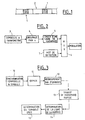
- Figure 1 shows the shape of the synchronization channel.
- a synchronization word 1 is repeated on the synchronization channel, with a given periodicity. Between repetitions or occurrences of the detection word, the synchronization channel carries the system information 2 broadcast to the user stations.
- the size, structure and power of the detection word depend on the characteristics of the system in question, and are chosen so as to allow the acquisition and if necessary the continuation of synchronization by the stations user.
- the detection word also called in the single word practice has strong autocorrelation and has a low probability appearing in transmitted messages. These properties facilitate word detection detection on the channel.
- Repeating the detection word in the synchronization channel allows a user station to acquire synchronization in time, by recognizing the word detected in the logical channel. In addition, recognition of the detected word allows a user station to acquire symbol synchronization.
- An appropriate choice of the position of the detection word (s) in the frame can also be used to acquire a user station to acquire the frame synchronization.
- the repetition of the detection word is therefore carried out preferably with a period corresponding to the frame period. Inside of a frame, the repetition of the detected word can be periodic or not. In others terms, to allow the acquisition of a frame synchronization, repetitions of the detection word advantageously form in the channel a periodic pattern, whose period is a sub-multiple or multiple of a frame period of the channel.
- the detection word can also be repeated only once per frame.
- the detection word is repeated periodically, with a period which is a sub-multiple or a multiple of the frame period.
- a user station can then acquire symbol and frame synchronization by simple recognition of the detection word.
- a first frequency estimate is possible, by techniques known per se, such as the phase method developed.
- the invention proposes to broadcast the system information.
- the invention thus makes it possible to avoid consuming system resources, and reduces the impact of acquisition and synchronization functions on the capacity of transmission of the system.
- the solution of the invention also makes it possible to vary the useful throughput of system information broadcast, without spectrum changes.
- the system information is transmitted on the channel logic after a spread, and we transmit to each symbol of the logical channel not not a system information symbol, but a snippet (or "chips" in language English) resulting from the spread of system information symbols.
- the flow of broadcast in terms of the number of system information symbols broadcast by second, or real flow of information, is then lower; however, the spread system information is still possible, while using only one logical channel, mainly due to the low throughput of system information.
- This embodiment makes it possible to increase the signal-to-noise ratio of the system information symbols, for a given level of signal-to-noise ratio in the logical channel. This ensures that even the most user stations disadvantaged from the point of view of propagation properly receive the system information; the invention thus ensures good robustness.
- Spreading system information symbols can be done by spreading techniques known per se, for example described in M.K. Simon and others, Spread spectrum communications, Computer Sciences Press, 1988. The remainder of the description gives reference to FIG. 2 an example of implementation for Hadamard codes as M-ary modulation.
- the use of Hadamard codes for spreading system information before it is broadcast on the synchronization channel between the detection words is particularly advantageous, since demodulation is inconsistent; this increases resistance to phase and frequency variations
- the implementation of such codes is simple.
- Figure 2 shows a schematic representation of a transmitter for a synchronization channel according to the invention.
- the example in the figure uses a Hadamard M-ary modulation for spreading information symbols system, and QPSK modulation ("quaternary phase shift keying", or in French four-phase phase shift modulation) of the carrier.
- the system information symbols to be transmitted - reference 3 in the figure - are first grouped by groups of n, as indicated in 4. In 5, we then associate with each group of n symbols a line of the Hadamard matrix, ie 2 n symbols or Hadamard symbols, at the rate of the carrier.
- the corresponding M-ary modulation constitutes a spread of the system information symbols to be transmitted.
- the Hadamard symbols obtained after spreading are transmitted to a multiplexer 6. This also receives the symbols of the detection word, see reference 7 in the figure.
- the multiplexer 6 performs the multiplexing of the symbols of Hadamard, and symbols of the detection word to obtain a structure of symbols like the one in Figure 1.
- System information symbols at nominal carrier rate multiplexed with the symbols of the detection word, are then modulated on the channel logic.
- the treatments may then vary.
- the symbols modulated on the carrier are oversampled, then multiplied by the sequence or code corresponding to the channel, before being sent on the channel physical.
- the system information is transmitted at a rate Dn / 2 n on the logical channel. This is the instantaneous flow rate, which does not take into account the space occupied on the carrier by the detection word.
- the power of the detection words in the channel can be different from the power of the system information transmitted. This is especially the case if the system information, as in the described embodiment, is transmitted after a first spread; indeed, in this case, the first spread increases the signal-to-noise ratio of system information. They can then be transmitted at a lower level, while being received by the stations users with the worst reception conditions.
- Figure 3 shows a schematic representation of a receiver for a synchronization channel according to the invention, which can operate with the transmitter of the figure 2.
- the symbols received on the logical channel - in the case after if necessary the acquisition of a synchronization on the scraps in the case of logical channels in CDMA - are transmitted to a block 10 for acquiring time synchronization and symbol synchronization; in this block 10, the receiver searches for the word of detection and also performs frame synchronization if necessary. We can this instant proceed to a first estimate of the frequency, as explained more high.
- the symbols are then demultiplexed, in 1 1, to separate the system information transmitted and the detection words.
- the system information received between the detection words at the nominal bit rate of the channel is then grouped into groups of 2 n symbols, in block 12.
- the information symbols are determined at 15.
- the invention thus makes it possible to estimate the frequency difference and the difference in phase.
- This estimate allows on the one hand a continuation of the physical channel, so that the user station remains hooked on the transmission frequency of the channel physical.
- this estimate allows a correction of the frequency and the phase of the signals received on the other logical channels of the same physical channel; the invention thus makes it possible to group the estimation function on a single channel the frequency and phase difference on a physical channel.
- Monitoring the detection words also makes it possible to maintain the time synchronization and symbol synchronization of the user station.
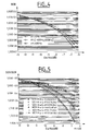
- FIG. 4 shows a graph of bit error rate as a function of the signal to noise ratio, for different frequency deviations; the signal to noise ratio E S / N 0 , in dB, is plotted on the abscissa and the error rate on the system information bits (BER) is plotted on the ordinate.
- the diamond graph shows the simulated results without frequency differences; the square graph shows the simulated results for a frequency difference between - 400 Hz and + 400 Hz, with an equiprobable distribution between these two values.
- the triangle graph shows the simulated results for a frequency difference of 400 Hz.
- the figure shows that a frequency error between -400 Hz and + 400 Hz only slightly degrades the bit error rate. For an E S / N 0 of -6.8 dB, we lose only 0.5 dB.
- the difference in phase and in advantage is determined. frequency not from Hadamard lines, but from symbols system information corrected by application of the error correction code. In fact, we go back from the system information symbols corrected to the line of Hadamard emitted, and we compare the emitted line (or several lines) with the symbols actually received on the carrier.
- FIG. 5 shows a graph of error rate on the system information bits (BER) or on the symbols obtained after spreading (SER), as a function of the signal to noise ratio, for different types of error correcting codes.
- the notations are the same as in FIG. 4.
- the graph in black diamonds shows the error rate on the symbols, and the graph in black triangles the error rate on the bits, without error correction code.
- the two square graphs show the error rate on the symbols and the error rate on the bits, with an error correction code of the Reed Solomon type (70, 84).
- the two square graphs show the error rate on the symbols and the error rate on the bits, with an error correction code of the Reed Solomon type (56, 84).
- the figure shows that the use of error correcting codes considerably improves the performance of the transmission system.
- the probability of a frequency error greater than 21 Hz is of the order of 10 -6 for a modulation of the bits of system information with 128 symbols.
- an error correction of the Reed Solomon type (8, 12) shortened code, which corrects two errors, we reach a probability of the order of 10 -8 .
- CDMA orthogonal codes
- TDMA time division
- FDMA frequency division
- the entire synchronization channel is used for acquisition and further synchronization, and for broadcasting informations; we could also only use part of the channel for these functions synchronization. In this case, the rest of the synchronization channel could be used for traffic.
Abstract
Description
La présente invention concerne le domaine des communications par voie hertzienne ou radiocommunications. Elle concerne plus précisément l'acquisition et la poursuite en temps et en fréquence dans les systèmes de radiocommunications. Elle s'applique notamment aux systèmes de radiocommunications cellulaires, aux systèmes de radiocommunications cellulaires par satellites, ou aux autres systèmes de radiocommunication sans fil.The present invention relates to the field of communications by channel radio or radio communications. It relates more precisely to the acquisition and time and frequency tracking in radiocommunication systems. She applies in particular to cellular radio systems, cellular radiocommunication systems by satellite, or other systems of wireless radiocommunication.
Dans de tels systèmes de radiocommunications, se posent les problèmes de synchronisation des différents terminaux ou stations qui communiquent dans le système, de sorte à permettre une démodulation correcte des signaux transmis. Une station utilisateur, qui ne dispose généralement pas de moyens précis de génération d'horloge, doit acquérir une synchronisation en temps et en fréquence avec une station émettrice, pour pouvoir démoduler les signaux qu'elle reçoit en provenance de cette station émettrice. Il est aussi indispensable qu'une station utilisateur puisse effectuer la poursuite en temps et en fréquence, c'est-à-dire conserver au cours d'une communication la synchronisation en temps et en fréquence lui permettant de continuer à démoduler correctement les signaux qu'elle reçoit.In such radiocommunication systems, there are the problems of synchronization of the various terminals or stations which communicate in the system, so as to allow correct demodulation of the transmitted signals. A user station, which generally does not have precise means of generation clock, must acquire time and frequency synchronization with a transmitting station, in order to demodulate the signals it receives from this transmitting station. It is also essential that a user station can carry out the tracking in time and in frequency, that is to say keep during a communication time and frequency synchronization allowing it to continue to properly demodulate the signals it receives.
Ce problème se pose notamment pour les systèmes utilisant une modulation à étalement de spectre, pour lesquels seule l'acquisition de la synchronisation permet la démodulation. Il se pose aussi pour les systèmes de satellites en orbite basse, pour lesquels les satellites assurant la couverture géographique pour une station utilisateur donnée varient.This problem arises in particular for systems using modulation spread spectrum, for which only the acquisition of synchronization allows demodulation. It also arises for low-orbit satellite systems, for which satellites providing geographic coverage for a user station given vary.
On définit dans de tels systèmes de radiocommunications des canaux physiques, qui permettent la transmission des informations, et correspondent typiquement à une fréquence de porteuse; ces canaux physiques sont divisés en canaux logiques, par exemple par division temporelle ou par division de code, de sorte à assurer un accès multiple sur un canal physique unique. L'accès multiple à division temporelle (TDMA) et l'accès multiple à division par codes (CDMA) sont connus en soi.In such radiocommunication systems, channels are defined physical, which allow the transmission of information, and correspond typically at a carrier frequency; these physical channels are divided into logical channels, for example by time division or by code division, of so as to provide multiple access on a single physical channel. Multiple access to time division (TDMA) and code division multiple access (CDMA) are known per se.
La communication avec les stations utilisateurs dans un système de radiocommunications nécessite en outre la diffusion d'informations système vers les stations, en utilisant un canal logique associé à un canal physique. Ces informations systèmes comprennent par exemple le nom ou le numéro de station de base ("gateway"), ou la localisation géographique en terme de cellule. On parlera dans la suite de diffusion la transmission de telles informations système, et on utilisera le terme trafic pour ce qui concerne le contenu des messages échangés entre les utilisateurs. Le débit des informations système est le plus souvent assez faible par rapport au débit du trafic, et est typiquement de quelques kilobits par seconde.Communication with user stations in a communication system radio communications also requires the dissemination of system information to stations, using a logical channel associated with a physical channel. These informations systems for example include base station name or number ("gateway"), or the geographic location in terms of cell. We will talk in the following the transmission of such system information, and we will use the traffic term for the content of messages exchanged between users. The rate of system information is most often quite low by traffic flow rate, and is typically a few kilobits per second.
Une des contraintes dans un tel système de radiocommunications est d'atteindre toutes les stations utilisateurs dans la zone de couverture, y compris celles qui sont le plus défavorisées du point de vue de la propagation. A cette contrainte s'ajoutent les contraintes liées à la limitation des ressources spectrales et de puissance propres à chaque type de système.One of the constraints in such a radiocommunication system is reach all user stations in the coverage area, including those who are most disadvantaged from a propagation perspective. To this constraint there are also the constraints linked to the limitation of spectral and power resources specific to each type of system.
Pour remplir ces fonctions d'acquisition et de poursuite de la synchronisation, et de diffusion d'informations système, il a été proposé d'utiliser plusieurs canaux physiques, comme par exemple un canal pilote non modulé à forte puissance, et un autre canal physique pour la diffusion des informations. Le canal pilote non modulé permet un accrochage facile de la station utilisateur sur la fréquence du canal, et une synchronisation en temps. La synchronisation en fréquence est acquise par des méthodes connues en soi, du type transformée de Fourier rapide (FFT). Cette méthode du pilote non modulé est notamment mise en oeuvre dans le système Qualcomm de radiocommunications en CDMA.To fulfill these functions of acquisition and further synchronization, and dissemination of system information, it was proposed to use multiple channels physical, such as a high power unmodulated pilot channel, and a another physical channel for the dissemination of information. The unmodulated pilot channel allows easy hooking of the user station on the channel frequency, and a time synchronization. Frequency synchronization is acquired by methods known per se, of the fast Fourier transform type (FFT). This unmodulated pilot method is notably implemented in the system Qualcomm of radiocommunications in CDMA.
Cette solution présente des inconvénients. L'utilisation d'un canal non modulé de forte puissance permet de simplifier la synchronisation en temps, mais provoque une dépense de puissance importante. En outre, l'utilisation d'un canal physique non modulé occupe plusieurs ressources logiques, et peut diminuer la capacité du système. Enfin, cette solution implique un séquencement de procédures assez complexe; il convient d'abord d'acquérir la synchronisation en temps et la synchronisation en fréquence, sur le canal non modulé, puis de passer sur un autre canal logique pour recevoir les informations système et ensuite démoduler les canaux de trafic.This solution has drawbacks. Using a non-channel high power modulated simplifies synchronization in time, but causes a significant power expenditure. In addition, the use of a channel unmodulated physics occupies several logical resources, and can decrease the system capacity. Finally, this solution involves a sequencing of procedures fairly complex; it is first necessary to acquire the synchronization in time and the frequency synchronization, on the unmodulated channel, then switch to another logical channel to receive system information and then demodulate the channels traffic.
L'invention propose une solution au problème de l'acquisition et de la poursuite de la synchronisation dans un système de radiocommunications. Elle propose en outre une solution au problème de la diffusion d'informations vers les stations utilisateurs.The invention proposes a solution to the problem of acquisition and continued synchronization in a radiocommunication system. She also offers a solution to the problem of disseminating information to user stations.
A l'encontre des solutions connues, l'invention propose d'utiliser un seul canal logique, de préférence sans augmentation de puissance, pour la synchronisation et la poursuite de la synchronisation en temps et en fréquence, et pour la diffusion d'informations système.Unlike known solutions, the invention proposes to use a single logical channel, preferably without power increase, for the synchronization and continued synchronization in time and frequency, and for the dissemination of system information.
Elle permet ainsi d'économiser la puissance dépensée, de limiter l'occupation des ressources - canaux physiques - utilisées pour la synchronisation; elle permet aussi de simplifier les procédures d'acquisition et de poursuite de la synchronisation.It thus saves the power spent, limits occupancy resources - physical channels - used for synchronization; she permits also to simplify the procedures for acquiring and continuing synchronization.
Plus précisément, l'invention propose un canal de synchronisation pour un système de radiocommunications entre une pluralité de stations, comprenant un mot de détection répété sur le canal, et des informations système entre les répétitions du mot de détection.More specifically, the invention proposes a synchronization channel for a radiocommunication system between a plurality of stations, comprising a word detection channel and system information between repetitions of the detection word.
Avantageusement, les répétitions du mot de détection forment dans le canal un motif périodique, la période du motif étant un sous multiple ou un multiple d'une période de trame du canal.Advantageously, the repetitions of the detection word form in the channel a periodic pattern, the period of the pattern being a sub-multiple or a multiple of a channel frame period.
Le mot de détection peut aussi être répété périodiquement, avec une période sous multiple ou multiple d'une période de trame du canal.The detection word can also be repeated periodically, with a period under multiple or multiple of a frame period of the channel.
Dans un mode de réalisation préféré de l'invention, les informations système sont transmises sur le canal après étalement.In a preferred embodiment of the invention, the information system are transmitted on the channel after spreading.
L'étalement est avantageusement un étalement par modulation M-aire à l'aide d'un code de Hadamard.The spreading is advantageously spreading by M-ary modulation at using a Hadamard code.
De préférence, les informations système sont encodées par un code correcteur d'erreur avant étalementPreferably, the system information is encoded by a code error corrector before spreading
L'invention concerne aussi un système de radiocommunications, présentant un tel canal de synchronisation.The invention also relates to a radiocommunication system, having such a synchronization channel.
Le système comprend avantageusement une pluralité de canaux physiques, chaque canal physique comprenant au moins un canal logique ; le canal de synchronisation est alors un canal logique.The system advantageously comprises a plurality of physical channels, each physical channel comprising at least one logical channel; the channel of synchronization is then a logical channel.
De préférence, les canaux logiques sont définis par accès multiple à division par codes. Preferably, the logical channels are defined by division multiple access by codes.
D'autres caractéristiques et avantages de l'invention apparaítront à la lecture de la description qui suit de modes de réalisation de l'invention, donnée à titre d'exemple et en référence aux dessins annexés, qui montrent
- figure 1, une représentation schématique de l'allure d'un canal de synchronisation selon l'invention;
- figure 2, une représentation schématique d'un émetteur pour un tel canal;
- figure 3, une représentation schématique d'un récepteur pour un tel canal ;
- figure 4, un graphe de taux d'erreur sur les bits en fonction du rapport signal sur bruit, pour différents écarts en fréquence ;
- figure 5, un graphe de taux d'erreur sur les bits en fonction du rapport signal sur bruit, pour différents types de codes correcteurs d'erreur.
- Figure 1, a schematic representation of the shape of a synchronization channel according to the invention;
- Figure 2, a schematic representation of a transmitter for such a channel;
- Figure 3, a schematic representation of a receiver for such a channel;
- FIG. 4, a graph of bit error rate as a function of the signal to noise ratio, for different frequency deviations;
- FIG. 5, a graph of bit error rate as a function of the signal to noise ratio, for different types of error correcting codes.
Dans la suite de la description, l'invention est décrite en référence à un système de radiocommunications à satellites en orbite basse et à spectre étalé, avec un accès multiple par division de codes. Elle ne s'applique bien entendu pas qu'à un tel système.In the following description, the invention is described with reference to a low-orbit spread-spectrum satellite radio system with multiple access by code division. It of course does not only apply to a such system.
Dans un tel système, sur une même porteuse constituant un canal physique sont multiplexés différents signaux étalés par multiplication par des codes orthogonaux. L'orthogonalité des codes assure que chaque station d'utilisateur peut par multiplication par son propre code, récupérer les signaux qui lui sont destinés.In such a system, on the same carrier constituting a physical channel are multiplexed different signals spread by multiplication by codes orthogonal. The orthogonality of the codes ensures that each user station can by multiplying by its own code, retrieving the signals intended for it.
Chaque code définit un canal logique, qui peut être utilisé pour le trafic ou la diffusion d'information système; on peut définir une trame, qui peut elle-même être divisée en intervalles de temps élémentaires; la taille du code, ou des intervalles de temps, ainsi que les débits correspondants dépendent des caractéristiques de chaque système, et peuvent varier.Each code defines a logical channel, which can be used for traffic or dissemination of system information; we can define a frame, which can itself be divided into elementary time intervals; the size of the code, or intervals of time, as well as the corresponding flow rates depend on the characteristics of each system, and may vary.
L'invention propose d'utiliser pour l'ensemble des fonctions d'acquisition et de poursuite de la synchronisation, et de diffusion des informations système, un canal logique unique, de préférence, sans augmentation de puissance. Dans la suite de la description, le canal correspondant est appelé canal de synchronisation. Dans l'exemple de canaux logiques définis par des codes orthogonaux, comme ci-dessus, on utilise avantageusement un des codes pour définir le canal de synchronisation; pour d'autres types de modulation, le canal de synchronisation correspond à un canal logique, c'est-à-dire à tout ou partie d'une porteuse ou d'un canal physique.The invention proposes to use for all of the acquisition and to continue synchronization, and broadcast system information, one channel unique logic, preferably, without power increase. In the rest of the description, the corresponding channel is called the synchronization channel. In the example of logical channels defined by orthogonal codes, as above, one of the codes is advantageously used to define the synchronization channel; for other types of modulation, the synchronization channel corresponds to a logical channel, that is to say to all or part of a carrier or a physical channel.
La figure 1 montre l'allure du canal de synchronisation. Comme le montre la
figure, un mot de synchronisation 1 est répété sur le canal de synchronisation, avec
une périodicité donnée. Entre les répétitions ou occurrences du mot de détection, le
canal de synchronisation transporte les informations système 2 diffusées vers les
stations utilisateur.Figure 1 shows the shape of the synchronization channel. As the
figure, a
La taille, la structure et la puissance du mot de détection dépendent des caractéristiques du système en cause, et sont choisies de sorte à permettre l'acquisition et le cas échéant la poursuite de la synchronisation par les stations utilisateur. De façon connue en soi, le mot de détection, aussi appelé dans la pratique "mot unique" présente une forte autocorrélation et a une faible probabilité d'apparition dans les messages transmis. Ces propriétés facilitent la détection du mot de détection sur le canal.The size, structure and power of the detection word depend on the characteristics of the system in question, and are chosen so as to allow the acquisition and if necessary the continuation of synchronization by the stations user. In a manner known per se, the detection word, also called in the single word practice has strong autocorrelation and has a low probability appearing in transmitted messages. These properties facilitate word detection detection on the channel.
La répétition du mot de détection dans le canal de synchronisation permet à une station utilisateur d'acquérir la synchronisation en temps, par reconnaissance du mot détecté dans le canal logique. En outre, la reconnaissance du mot détecté permet à une station utilisateur d'acquérir la synchronisation symbole.Repeating the detection word in the synchronization channel allows a user station to acquire synchronization in time, by recognizing the word detected in the logical channel. In addition, recognition of the detected word allows a user station to acquire symbol synchronization.
Un choix approprié de la position du ou des mots de détection dans la trame peut aussi permettre d'acquérir à une station utilisateur d'acquérir la synchronisation trame. La répétition du mot de détection s'effectue donc de préférence avec une période correspondant à la période des trames. A l'intérieur d'une trame, la répétition du mot détecté peut être périodique ou non. En d'autres termes, pour permettre une l'acquisition d'une synchronisation trame, les répétitions du mot de détection forment avantageusement dans le canal un motif périodique, dont la période est un sous multiple ou multiple d'une période de trame du canal. Le mot de détection peut aussi n'être répété qu'une seule fois par trame.An appropriate choice of the position of the detection word (s) in the frame can also be used to acquire a user station to acquire the frame synchronization. The repetition of the detection word is therefore carried out preferably with a period corresponding to the frame period. Inside of a frame, the repetition of the detected word can be periodic or not. In others terms, to allow the acquisition of a frame synchronization, repetitions of the detection word advantageously form in the channel a periodic pattern, whose period is a sub-multiple or multiple of a frame period of the channel. The detection word can also be repeated only once per frame.
Dans le cas le plus simple, le mot de détection est répété périodiquement, avec une période qui est un sous multiple ou un multiple de la période de trame. Une station utilisateur peut alors acquérir la synchronisation symbole et trame par simple reconnaissance du mot de détection.In the simplest case, the detection word is repeated periodically, with a period which is a sub-multiple or a multiple of the frame period. A user station can then acquire symbol and frame synchronization by simple recognition of the detection word.
A titre d'exemple, on considère le cas de canaux logiques, définis par des codes orthogonaux d'une longueur de 128 symboles, avec une trame composée de 24 intervalles de temps d'une longueur unitaire de 424 symboles. Dans ce cas, on peut utiliser un mot de détection d'une longueur de 80 symboles, qui est répété une fois tous les deux intervalles de temps.As an example, we consider the case of logical channels, defined by orthogonal codes with a length of 128 symbols, with a frame composed of 24 time intervals with a unit length of 424 symbols. In this case, we can use a detection word with a length of 80 symbols, which is repeated one times every two time intervals.
Après acquisition de la synchronisation en temps et de la synchronisation symbole et trame, une première estimation de fréquence est possible, par des techniques connues en soi, comme par exemple par la méthode de phase développée.After acquisition of time synchronization and synchronization symbol and frame, a first frequency estimate is possible, by techniques known per se, such as the phase method developed.
Entre les occurrences du mot de détection, l'invention propose de diffuser les informations système. On arrive ainsi à transmettre sur un canal logique unique l'ensemble des éléments nécessaires à la synchronisation des stations utilisateurs. L'invention permet ainsi d'éviter de consommer des ressources système, et réduit l'impact des fonctions d'acquisition et de synchronisation sur la capacité de transmission du système. La solution de l'invention permet aussi de faire varier le débit utile des informations système diffusées, sans modifications du spectre.Between the occurrences of the detection word, the invention proposes to broadcast the system information. We thus manage to transmit on a single logical channel all the elements necessary for the synchronization of user stations. The invention thus makes it possible to avoid consuming system resources, and reduces the impact of acquisition and synchronization functions on the capacity of transmission of the system. The solution of the invention also makes it possible to vary the useful throughput of system information broadcast, without spectrum changes.
Avantageusement, les informations système sont transmises sur le canal logique après un étalement, et on transmet à chaque symbole du canal logique non pas un symbole d'information système, mais une bribe (ou "chips" en langue anglaise) résultant de l'étalement des symboles d'information système. Le débit de diffusion, en terme de nombre de symboles d'information système diffusés par seconde, ou débit réel des informations, est alors plus faible; toutefois, l'étalement des informations système reste possible, tout en n'utilisant qu'un seul canal logique, du fait notamment du faible débit des informations système.Advantageously, the system information is transmitted on the channel logic after a spread, and we transmit to each symbol of the logical channel not not a system information symbol, but a snippet (or "chips" in language English) resulting from the spread of system information symbols. The flow of broadcast, in terms of the number of system information symbols broadcast by second, or real flow of information, is then lower; however, the spread system information is still possible, while using only one logical channel, mainly due to the low throughput of system information.
Le fait que le débit réel des informations système soit plus faible que le débit nominal de la porteuse permet de combattre des atténuations plus fortes, et de mieux résister aux écarts de fréquence, grâce aussi à la modulation utilisée.The fact that the actual rate of system information is lower than the rate nominal of the carrier makes it possible to combat stronger attenuations, and better resist frequency deviations, also thanks to the modulation used.
Ce mode de réalisation permet d'augmenter le rapport signal à bruit des symboles d'information système, pour un niveau donné du rapport signal à bruit dans le canal logique. On assure ainsi que même les stations utilisateur les plus défavorisées du point de vue de la propagation reçoivent correctement les informations système; l'invention assure de la sorte une bonne robustesse. L'étalement des symboles d'information système peut s'effectuer par les techniques d'étalement connues en soi, par exemple décrites dans M.K. Simon et autres, Spread spectrum communications, Computer Sciences Press, 1988. La suite de la description donne en référence à la figure 2 un exemple de mise en oeuvre pour des codes de Hadamard en tant que modulation M-aire. L'utilisation de codes de Hadamard pour l'étalement des informations système avant leur diffusion sur le canal de synchronisation entre les mots de détection est particulièrement avantageuse, du fait que la démodulation est non cohérente; ceci augmente la résistance aux variations de phase et de fréquenceThis embodiment makes it possible to increase the signal-to-noise ratio of the system information symbols, for a given level of signal-to-noise ratio in the logical channel. This ensures that even the most user stations disadvantaged from the point of view of propagation properly receive the system information; the invention thus ensures good robustness. Spreading system information symbols can be done by spreading techniques known per se, for example described in M.K. Simon and others, Spread spectrum communications, Computer Sciences Press, 1988. The remainder of the description gives reference to FIG. 2 an example of implementation for Hadamard codes as M-ary modulation. The use of Hadamard codes for spreading system information before it is broadcast on the synchronization channel between the detection words is particularly advantageous, since demodulation is inconsistent; this increases resistance to phase and frequency variations
On peut prévoir pour les informations système transmises entre les occurrences du mot de détection d'utiliser des codes correcteurs d'erreur. L'implémentation de tels codes est simple.Provision can be made for system information transmitted between occurrences of the detection word to use error correcting codes. The implementation of such codes is simple.
La figure 2 montre une représentation schématique d'un émetteur pour un canal de synchronisation selon l'invention. L'exemple de la figure utilise une modulation M-aire de Hadamard pour l'étalement des symboles d'information système, et une modulation QPSK ("quaternary phase shift keying", ou en français modulation en décalage de phase à quatre symboles) de la porteuse.Figure 2 shows a schematic representation of a transmitter for a synchronization channel according to the invention. The example in the figure uses a Hadamard M-ary modulation for spreading information symbols system, and QPSK modulation ("quaternary phase shift keying", or in French four-phase phase shift modulation) of the carrier.
Les symboles d'information système à transmettre - référence 3 sur la figure
- sont d'abord regroupés par groupes de n, comme indiqué en 4. En 5, on associe
ensuite à chaque groupe de n symboles une ligne de la matrice de Hadamard, i.e.
2n symboles ou symboles de Hadamard, au débit de la porteuse. La modulation M-aire
correspondante constitue un étalement des symboles d'information système à
transmettre.The system information symbols to be transmitted -
Les symboles de Hadamard obtenus après étalement sont transmis à un
multiplexeur 6. Celui-ci reçoit par ailleurs les symboles du mot de détection, voir
référence 7 sur la figure. Le multiplexeur 6 effectue le multiplexage des symboles de
Hadamard, et des symboles du mot de détection pour obtenir une structure des
symboles du genre de celle de la figure 1.The Hadamard symbols obtained after spreading are transmitted to a
Les symboles d'information système au débit nominal de la porteuse, multiplexés avec les symboles du mot de détection, sont ensuite modulés sur le canal logique. En fonction de la nature du canal logique, et du canal physique, les traitements peuvent alors varier. Dans le cas d'un accès multiple à division par codes, les symboles modulés sur la porteuse sont suréchantillonnés, puis multipliés par la séquence ou le code correspondant au canal, avant d'être envoyés sur le canal physique. System information symbols at nominal carrier rate, multiplexed with the symbols of the detection word, are then modulated on the channel logic. Depending on the nature of the logical channel, and the physical channel, the treatments may then vary. In the case of multiple access divided by codes, the symbols modulated on the carrier are oversampled, then multiplied by the sequence or code corresponding to the channel, before being sent on the channel physical.
Pour un débit porteuse D, les informations système sont transmises à un débit D.n/2n sur le canal logique. Il s'agit là du débit instantané, qui ne tient pas compte de la place occupée sur la porteuse par le mot de détection.For a carrier rate D, the system information is transmitted at a rate Dn / 2 n on the logical channel. This is the instantaneous flow rate, which does not take into account the space occupied on the carrier by the detection word.
On notera que la puissance des mots de détection dans le canal peut être différente de la puissance des informations système transmises. Ceci est notamment le cas si les informations système, comme dans le mode de réalisation décrit, sont transmises après un premier étalement; en effet, dans ce cas, le premier étalement permet d'augmenter le rapport signal à bruit des informations système. Elles peuvent alors être transmises à un niveau plus faible, tout en étant reçues par les stations utilisateurs ayant les conditions de réception les plus mauvaises.Note that the power of the detection words in the channel can be different from the power of the system information transmitted. This is especially the case if the system information, as in the described embodiment, is transmitted after a first spread; indeed, in this case, the first spread increases the signal-to-noise ratio of system information. They can then be transmitted at a lower level, while being received by the stations users with the worst reception conditions.
La figure 3 montre une représentation schématique d'un récepteur pour un
canal de synchronisation selon l'invention, qui peut fonctionner avec l'émetteur de la
figure 2. Les symboles reçus sur le canal logique - dans le cas après le cas échéant
l'acquisition d'une synchronisation sur les bribes dans le cas de canaux logiques en
CDMA - sont transmis à un bloc 10 d'acquisition de la synchronisation temporelle et
de la synchronisation symbole; dans ce bloc 10, le récepteur recherche le mot de
détection et procède aussi le cas échéant à la synchronisation de trame. On peut à
cet instant procéder à une première estimation de la fréquence, comme expliqué plus
haut.Figure 3 shows a schematic representation of a receiver for a
synchronization channel according to the invention, which can operate with the transmitter of the
figure 2. The symbols received on the logical channel - in the case after if necessary
the acquisition of a synchronization on the scraps in the case of logical channels in
CDMA - are transmitted to a
Les symboles sont ensuite démultiplexés, en 1 1, pour séparer l'information
système transmise et les mots de détection. L'information système reçue entre les mots
de détection au débit nominal du canal est alors regroupée par groupes de 2n
symboles, dans le bloc 12.The symbols are then demultiplexed, in 1 1, to separate the system information transmitted and the detection words. The system information received between the detection words at the nominal bit rate of the channel is then grouped into groups of 2 n symbols, in
On procède ensuite à une transformée de Hadamard rapide des groupes de 2n symboles, en 13. On détermine ensuite la ligne de la matrice de Hadamard émise, en 14, de sorte à obtenir n symboles d'information émis; on utilise typiquement comme critère le maximum de vraisemblance sur la ligne de la matrice de Hadamard.We then proceed to a fast Hadamard transform of the groups of 2 n symbols, at 13. We then determine the line of the Hadamard matrix emitted, at 14, so as to obtain n emitted information symbols; we typically use as a criterion the maximum likelihood on the line of the Hadamard matrix.
La connaissance de la ligne de Hadamard émise, et des 2n symboles de Hadamard reçus sur la porteuse permet une estimation a posteriori de l'écart en fréquence et de l'écart en phase.Knowledge of the Hadamard line sent, and of the 2 n Hadamard symbols received on the carrier allows an a posteriori estimate of the frequency difference and the phase difference.
On détermine en 15 les symboles d'information. The information symbols are determined at 15.
Outre la diffusion des informations système aux stations utilisateurs, l'invention permet de la sorte une estimation de l'écart en fréquence et de l'écart en phase. Cette estimation permet d'une part une poursuite du canal physique, de sorte que la station utilisateur reste accrochée sur la fréquence d'émission du canal physique. D'autre part, cette estimation permet une correction de la fréquence et de la phase des signaux reçus sur les autres canaux logiques du même canal physique; l'invention permet de la sorte de regrouper sur un seul canal la fonction d'estimation de l'écart en fréquence et en phase sur un canal physique.In addition to broadcasting system information to user stations, the invention thus makes it possible to estimate the frequency difference and the difference in phase. This estimate allows on the one hand a continuation of the physical channel, so that the user station remains hooked on the transmission frequency of the channel physical. On the other hand, this estimate allows a correction of the frequency and the phase of the signals received on the other logical channels of the same physical channel; the invention thus makes it possible to group the estimation function on a single channel the frequency and phase difference on a physical channel.
Le suivi des mots de détection permet en outre de maintenir la synchronisation temporelle et la synchronisation symbole de la station utilisateur.Monitoring the detection words also makes it possible to maintain the time synchronization and symbol synchronization of the user station.
La figure 4 montre un graphe de taux d'erreur sur les bits en fonction du rapport signal sur bruit, pour différents écarts en fréquence ; est porté en abscisses le rapport signal sur bruit ES/N0, en dB, et en ordonnées le taux d'erreur sur les bits d'information système (BER). La figure correspond au cas d'un étalement de l'information système par une modulation M-aire par codes de Hadamard, avec 2n = 128. Le graphe en losanges montre les résultats simulés sans écarts en fréquence ; le graphe en carrés montre les résultats simulés pour un écart en fréquence entre - 400 Hz et + 400 Hz, avec une distribution équiprobable entre ces deux valeurs. Le graphe en triangles montre les résultats simulés pour un écart en fréquence de 400 Hz. La figure montre qu'une erreur de fréquence entre -400 Hz et + 400 Hz ne dégrade que faiblement le taux d'erreur sur les bits. Pour un ES/N0 de -6,8 dB, on ne perd que 0,5 dB.FIG. 4 shows a graph of bit error rate as a function of the signal to noise ratio, for different frequency deviations; the signal to noise ratio E S / N 0 , in dB, is plotted on the abscissa and the error rate on the system information bits (BER) is plotted on the ordinate. The figure corresponds to the case of spreading of system information by an M-ary modulation by Hadamard codes, with 2 n = 128. The diamond graph shows the simulated results without frequency differences; the square graph shows the simulated results for a frequency difference between - 400 Hz and + 400 Hz, with an equiprobable distribution between these two values. The triangle graph shows the simulated results for a frequency difference of 400 Hz. The figure shows that a frequency error between -400 Hz and + 400 Hz only slightly degrades the bit error rate. For an E S / N 0 of -6.8 dB, we lose only 0.5 dB.
On n'a pas représenté à la figure le cas d'utilisation d'un code correcteur
d'erreur. On peut typiquement utiliser un tel code pour les symboles d'informations,
avant l'étalement par le code de Hadamard, auquel cas on procède à la correction
dans le schéma de la figure 3 après le bloc 14.The case of using a correction code has not been shown in the figure
error. We can typically use such a code for information symbols,
before spreading by Hadamard's code, in which case we proceed to the correction
in the diagram in Figure 3 after
Dans ce cas, on détermine avantageusement l'écart en phase et en fréquence non pas à partir des lignes de Hadamard, mais à partir des symboles d'information système corrigés par application du code correcteur d'erreurs. En fait, on remonte à partir des symboles d'information système corrigés à la ligne de Hadamard émise, et on compare la ligne émise (ou plusieurs lignes) aux symboles effectivement reçus sur la porteuse. In this case, the difference in phase and in advantage is determined. frequency not from Hadamard lines, but from symbols system information corrected by application of the error correction code. In fact, we go back from the system information symbols corrected to the line of Hadamard emitted, and we compare the emitted line (or several lines) with the symbols actually received on the carrier.
La figure 5 montre un graphe de taux d'erreur sur les bits d'information système (BER) ou sur les symboles obtenus après étalement (SER), en fonction du rapport signal sur bruit, pour différents types de codes correcteurs d'erreur. Les notations sont les mêmes que sur la figure 4. La figure correspond encore au cas d'un étalement de l'information système par une modulation M-aire par codes de Hadamard, avec 2n = 128. Le graphe en losanges noirs montre le taux d'erreur sur les symboles, et le graphe en triangles noirs le taux d'erreur sur les bits, sans code correcteur d'erreur. Les deux graphes en carrés montrent le taux d'erreur sur les symboles et le taux d'erreur sur les bits, avec un code correcteur d'erreur du type Reed Solomon (70, 84). Les deux graphes en carrés montrent le taux d'erreur sur les symboles et le taux d'erreur sur les bits, avec un code correcteur d'erreur du type Reed Solomon (56, 84). La figure montre que l'utilisation de codes correcteurs d'erreur améliore considérablement les performances du système de transmission.FIG. 5 shows a graph of error rate on the system information bits (BER) or on the symbols obtained after spreading (SER), as a function of the signal to noise ratio, for different types of error correcting codes. The notations are the same as in FIG. 4. The figure also corresponds to the case of spreading of the system information by an M-ary modulation by Hadamard codes, with 2 n = 128. The graph in black diamonds shows the error rate on the symbols, and the graph in black triangles the error rate on the bits, without error correction code. The two square graphs show the error rate on the symbols and the error rate on the bits, with an error correction code of the Reed Solomon type (70, 84). The two square graphs show the error rate on the symbols and the error rate on the bits, with an error correction code of the Reed Solomon type (56, 84). The figure shows that the use of error correcting codes considerably improves the performance of the transmission system.
En termes de probabilité d'erreur, la probabilité d'une erreur de fréquence supérieure à 21 Hz est de l'ordre de 10-6 pour une modulation des bits d'information système à 128 symboles. Avec une correction d'erreur du type Reed Solomon (8, 12), code raccourci, qui corrige deux erreurs, on atteint une probabilité de l'ordre de 10-8.In terms of probability of error, the probability of a frequency error greater than 21 Hz is of the order of 10 -6 for a modulation of the bits of system information with 128 symbols. With an error correction of the Reed Solomon type (8, 12), shortened code, which corrects two errors, we reach a probability of the order of 10 -8 .
Bien entendu, la présente invention n'est pas limitée aux exemples et modes de réalisation décrits et représentés, mais elle est susceptible de nombreuses variantes accessibles à l'homme de l'art.Of course, the present invention is not limited to the examples and modes described and represented, but it is likely to be numerous variants accessible to those skilled in the art.
Ainsi, dans le mode de réalisation de l'invention décrit plus haut est prévu un étalement des symboles d'information système utilisant des codes de Hadamard; ceci n'est pas indispensable pour la mise en oeuvre de l'invention, et on pourrait aussi utiliser d'autres types de codes ou d'étalement.Thus, in the embodiment of the invention described above is provided a spreading of system information symbols using Hadamard codes; this is not essential for the implementation of the invention, and one could also use other types of codes or spreading.
L'invention a aussi été décrite dans le cas de canaux logiques définis par des codes orthogonaux (CDMA); elle s'applique aussi à d'autres types d'accès multiples, à division temporelle (TDMA), ou à division fréquentielle (FDMA), ou encore à d'autres définitions des canaux logiques.The invention has also been described in the case of logical channels defined by orthogonal codes (CDMA); it also applies to other types of multiple access, time division (TDMA), or frequency division (FDMA), or other definitions of logical channels.
Dans le mode de réalisation décrit, l'ensemble du canal de synchronisation est utilisé pour l'acquisition et la poursuite de la synchronisation, et pour la diffusion des informations; on pourrait aussi n'utiliser pour ces fonctions qu'une partie du canal de synchronisation. Dans ce cas, le reste du canal de synchronisation pourrait être utilisé pour le trafic.In the embodiment described, the entire synchronization channel is used for acquisition and further synchronization, and for broadcasting informations; we could also only use part of the channel for these functions synchronization. In this case, the rest of the synchronization channel could be used for traffic.
Claims (9)
Applications Claiming Priority (2)
| Application Number | Priority Date | Filing Date | Title |
|---|---|---|---|
| FR9813374A FR2785118B1 (en) | 1998-10-26 | 1998-10-26 | CHANNEL ACQUISITION AND TRACKING MODULE FOR A RADIOCOMMUNICATION SYSTEM |
| FR9813374 | 1998-10-26 |
Publications (1)
| Publication Number | Publication Date |
|---|---|
| EP0998065A1 true EP0998065A1 (en) | 2000-05-03 |
Family
ID=9531970
Family Applications (1)
| Application Number | Title | Priority Date | Filing Date |
|---|---|---|---|
| EP99402640A Withdrawn EP0998065A1 (en) | 1998-10-26 | 1999-10-25 | Channel module for acquisition and tracking used in a radio communication system |
Country Status (10)
| Country | Link |
|---|---|
| US (1) | US6813307B1 (en) |
| EP (1) | EP0998065A1 (en) |
| JP (1) | JP2002529002A (en) |
| KR (1) | KR20010033604A (en) |
| CN (1) | CN1287724A (en) |
| AU (1) | AU6345499A (en) |
| BR (1) | BR9907061A (en) |
| FR (1) | FR2785118B1 (en) |
| TW (1) | TW432814B (en) |
| WO (1) | WO2000025450A1 (en) |
Families Citing this family (6)
| Publication number | Priority date | Publication date | Assignee | Title |
|---|---|---|---|---|
| JP3677185B2 (en) * | 1999-11-29 | 2005-07-27 | 株式会社東芝 | Code division multiplexing transmission system, transmitter and receiver |
| DE102005006893B4 (en) * | 2005-02-15 | 2011-11-24 | Siemens Ag | Radio station and method for transmitting data |
| US8023398B2 (en) | 2007-01-30 | 2011-09-20 | Qualcomm Incorporated | Using a single FHT to decode access-based handoff probes from multiple users |
| RU2510933C2 (en) * | 2012-06-22 | 2014-04-10 | Открытое акционерное общество "Российский институт мощного радиостроения" | Device for synchronisation in radio communication system with programmed operational frequency tuning |
| US20200305220A1 (en) * | 2016-03-31 | 2020-09-24 | Nec Corporation | Radio access network node, radio terminal, network node, and method therefor |
| CN111614373B (en) * | 2020-05-20 | 2021-08-10 | 北京升哲科技有限公司 | Spread spectrum signal transmission method, spread spectrum signal reception method, spread spectrum signal transmission device, spread spectrum signal reception device, and spread spectrum signal reception medium |
Citations (6)
| Publication number | Priority date | Publication date | Assignee | Title |
|---|---|---|---|---|
| US4688210A (en) * | 1985-03-29 | 1987-08-18 | U.S. Philips Corporation | Method of and arrangement for synchronizing the receiver arrangements in a digital multiplex transmission system |
| EP0729241A2 (en) * | 1995-02-21 | 1996-08-28 | AT&T Corp. | Dual mode code division multiple access communication system and method |
| EP0795971A2 (en) * | 1996-03-15 | 1997-09-17 | Matsushita Electric Industrial Co., Ltd. | Spread spectrum communication system for mobile system with synchronisation code |
| WO1997036383A1 (en) * | 1996-03-25 | 1997-10-02 | Stanford Telecommunications, Inc. | A rapid-acquisition access channel scheme for cdma systems |
| EP0814577A1 (en) * | 1996-06-19 | 1997-12-29 | Alcatel Espace | Interface unit for a mobile radio communication network |
| WO1998058464A1 (en) * | 1997-06-17 | 1998-12-23 | Siemens Aktiengesellschaft | Frequency synchronisation method for a mobile station in a mobile communications system |
Family Cites Families (8)
| Publication number | Priority date | Publication date | Assignee | Title |
|---|---|---|---|---|
| US3730998A (en) * | 1971-08-11 | 1973-05-01 | Communications Satellite Corp | Tdma satellite communications system with an aperture window for acquisition |
| US4455651A (en) * | 1980-10-20 | 1984-06-19 | Equatorial Communications Company | Satellite communications system and apparatus |
| US5258995A (en) * | 1991-11-08 | 1993-11-02 | Teknekron Communications Systems, Inc. | Wireless communication system |
| US5590160A (en) * | 1992-12-30 | 1996-12-31 | Nokia Mobile Phones Ltd. | Symbol and frame synchronization in both a TDMA system and a CDMA |
| US6094428A (en) * | 1997-04-30 | 2000-07-25 | Motorola, Inc. | Method and apparatus for transmission and reception of a transmission rate in a CDMA communication system |
| US6144650A (en) * | 1997-09-25 | 2000-11-07 | Matsushita Electric Industrial Co., Ltd. | Mobile communication system |
| JP3028800B2 (en) * | 1998-05-01 | 2000-04-04 | 日本電気株式会社 | CDMA cellular system and spreading code detection method in CDMA cellular system |
| CA2334898C (en) * | 1999-04-29 | 2007-06-05 | Samsung Electronics Co., Ltd. | Apparatus and method for synchronizing channels in a w-cdma communication system |
-
1998
- 1998-10-26 FR FR9813374A patent/FR2785118B1/en not_active Expired - Lifetime
-
1999
- 1999-10-25 US US09/581,043 patent/US6813307B1/en not_active Expired - Lifetime
- 1999-10-25 TW TW088118410A patent/TW432814B/en not_active IP Right Cessation
- 1999-10-25 AU AU63454/99A patent/AU6345499A/en not_active Abandoned
- 1999-10-25 EP EP99402640A patent/EP0998065A1/en not_active Withdrawn
- 1999-10-25 WO PCT/FR1999/002583 patent/WO2000025450A1/en not_active Application Discontinuation
- 1999-10-25 CN CN99801908A patent/CN1287724A/en active Pending
- 1999-10-25 KR KR1020007007117A patent/KR20010033604A/en not_active Application Discontinuation
- 1999-10-25 JP JP2000578932A patent/JP2002529002A/en active Pending
- 1999-10-25 BR BR9907061-8A patent/BR9907061A/en not_active Application Discontinuation
Patent Citations (6)
| Publication number | Priority date | Publication date | Assignee | Title |
|---|---|---|---|---|
| US4688210A (en) * | 1985-03-29 | 1987-08-18 | U.S. Philips Corporation | Method of and arrangement for synchronizing the receiver arrangements in a digital multiplex transmission system |
| EP0729241A2 (en) * | 1995-02-21 | 1996-08-28 | AT&T Corp. | Dual mode code division multiple access communication system and method |
| EP0795971A2 (en) * | 1996-03-15 | 1997-09-17 | Matsushita Electric Industrial Co., Ltd. | Spread spectrum communication system for mobile system with synchronisation code |
| WO1997036383A1 (en) * | 1996-03-25 | 1997-10-02 | Stanford Telecommunications, Inc. | A rapid-acquisition access channel scheme for cdma systems |
| EP0814577A1 (en) * | 1996-06-19 | 1997-12-29 | Alcatel Espace | Interface unit for a mobile radio communication network |
| WO1998058464A1 (en) * | 1997-06-17 | 1998-12-23 | Siemens Aktiengesellschaft | Frequency synchronisation method for a mobile station in a mobile communications system |
Also Published As
| Publication number | Publication date |
|---|---|
| KR20010033604A (en) | 2001-04-25 |
| WO2000025450A1 (en) | 2000-05-04 |
| BR9907061A (en) | 2000-10-17 |
| CN1287724A (en) | 2001-03-14 |
| AU6345499A (en) | 2000-05-15 |
| FR2785118A1 (en) | 2000-04-28 |
| US6813307B1 (en) | 2004-11-02 |
| FR2785118B1 (en) | 2004-06-18 |
| JP2002529002A (en) | 2002-09-03 |
| TW432814B (en) | 2001-05-01 |
Similar Documents
| Publication | Publication Date | Title |
|---|---|---|
| EP0565470B1 (en) | Method for transmission of digital radio-paging messages | |
| EP0556361B1 (en) | Data signal multiplexing method and device | |
| EP0278192B1 (en) | Method for digitally broadcasting in television channels | |
| EP0709980B1 (en) | Frequency synchronisation for OFDM system | |
| EP1878185B1 (en) | Method for the coding of an OFDM/OQAM signal using symbols with complex values, and corresponding signal, devices and computer programs | |
| FR2794915A1 (en) | TRANSMITTING METHOD AND DEVICE, RECEIVING METHOD AND DEVICE, AND SYSTEMS USING THE SAME | |
| FR2854020A1 (en) | Wireless data transmission method for cellular radio communication system, involves forming multi-carrier signal by temporal succession of symbols constituted of informative data units and drivers | |
| WO2004077774A1 (en) | Wireless data transmission method, and corresponding signal, system, transmitter and receiver | |
| EP0641096B1 (en) | Method with multiple access by orthogenal frequencies, corresponding central station, remote station, system and their use | |
| EP0616445B1 (en) | Duplex multicarrier digital radio communication system, mobile station and base station for it | |
| EP0998065A1 (en) | Channel module for acquisition and tracking used in a radio communication system | |
| CA2209476C (en) | Process for communication on the channel of a first propagation path towards a second propagation path | |
| EP1733577B8 (en) | Cellular radiotelephone signal which enables synchronisation at a frame of a supplementary channel by means of symbol numbering | |
| EP0631406B1 (en) | Digital signal adapted to be received by receivers with demodulators for VSB modulated signals, as well as corresponding method of reception, method of transmission, receiving device and use | |
| EP0942542B1 (en) | Method of signal demodulation for transmitted sequences in a communication system | |
| EP0994580B1 (en) | Transmission method in a multiple access radiocommunication system | |
| FR2854009A1 (en) | Multi-carrier signal constructing method for cellular network, involves inserting null energy component in data units and positioning energy components at locations corresponding to location of reference components | |
| FR2934102A1 (en) | METHOD FOR TIME SYNCHRONIZATION OF DIGITAL SIGNAL, CORRESPONDING DEVICE AND COMPUTER PROGRAM PRODUCT | |
| EP1128590A1 (en) | Synchronisation system of a digital multiple access telecommunication system | |
| EP0944979B1 (en) | Method for digital transmission or radio broadcast | |
| WO2006069872A1 (en) | Method and device for transmitting a multicarrier signal with time shifting of a subset of symbol elements, corresponding signal, reception method and device | |
| FR2697956A1 (en) | Mobile phone inter-communication e.g. between vehicles using TDMA - using digital words passing as clock step transmission for producing time slices of successive frames with synchronisation bit | |
| FR2799596A1 (en) | Equipment for optimising a multicarrier modulation transmission system, comprises one multicarrier modulator which favors a minimum error rate and a second which favors maximum information flow | |
| FR2866507A1 (en) | Cellular telephony signal, has additional OFDM high-speed downlink packet access line presenting sub-frame structure, where start of sub frame is off-centered from non-zero duration time interval relative to instant on main UMTS line | |
| WO2007068666A1 (en) | High rate data transmission system suitable hf channel transmission using standard transceivers |
Legal Events
| Date | Code | Title | Description |
|---|---|---|---|
| PUAI | Public reference made under article 153(3) epc to a published international application that has entered the european phase |
Free format text: ORIGINAL CODE: 0009012 |
|
| AK | Designated contracting states |
Kind code of ref document: A1 Designated state(s): AT BE CH CY DE DK ES FI FR GB GR IE IT LI LU MC NL PT SE |
|
| AX | Request for extension of the european patent |
Free format text: AL;LT;LV;MK;RO;SI |
|
| 17P | Request for examination filed |
Effective date: 20001103 |
|
| AKX | Designation fees paid |
Free format text: AT BE CH CY DE DK ES FI FR GB GR IE IT LI LU MC NL PT SE |
|
| 17Q | First examination report despatched |
Effective date: 20041020 |
|
| STAA | Information on the status of an ep patent application or granted ep patent |
Free format text: STATUS: THE APPLICATION IS DEEMED TO BE WITHDRAWN |
|
| 18D | Application deemed to be withdrawn |
Effective date: 20050503 |