EP1075084A2 - Method and apparatus for generating random signals - Google Patents
Method and apparatus for generating random signals Download PDFInfo
- Publication number
- EP1075084A2 EP1075084A2 EP00306612A EP00306612A EP1075084A2 EP 1075084 A2 EP1075084 A2 EP 1075084A2 EP 00306612 A EP00306612 A EP 00306612A EP 00306612 A EP00306612 A EP 00306612A EP 1075084 A2 EP1075084 A2 EP 1075084A2
- Authority
- EP
- European Patent Office
- Prior art keywords
- signal
- random
- preliminary
- signals
- noise source
- Prior art date
- Legal status (The legal status is an assumption and is not a legal conclusion. Google has not performed a legal analysis and makes no representation as to the accuracy of the status listed.)
- Granted
Links
Images


Classifications
-
- H—ELECTRICITY
- H03—ELECTRONIC CIRCUITRY
- H03K—PULSE TECHNIQUE
- H03K3/00—Circuits for generating electric pulses; Monostable, bistable or multistable circuits
- H03K3/84—Generating pulses having a predetermined statistical distribution of a parameter, e.g. random pulse generators
Definitions
- This invention relates to a method and apparatus for generating random signals, and particularly but not exclusively random binary waveforms.
- Random binary waveforms with specific correlation properties are required for ranging and other applications, especially in radar systems. It is particularly desirable to provide random binary waveforms with maximum unpredictability, hence with low probability of intercept, and also resistant to intelligent jamming. Furthermore, such random binary waveforms are also useful for applications in multi-user environments where many similar or disparate systems operate in the same geographical region and those systems share, at least partly, the same wide frequency band.
- LPI low probability of intercept
- the phase of the coherent carrier is modulated by a pseudo-random binary waveform to spread the spectrum of the transmitted signal.
- LPI low probability of intercept
- many similar radar systems should be capable of operating in the same region and sharing the same wide frequency band.
- each system should use a distinct signal, preferably orthogonal to the signals employed by all other systems. Therefore, the successful use of coded-waveform radar in a multi-user environment depends on the availability of large families of waveforms, each with specified correlation properties and low cross correlation values.
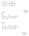
- Fig. 1 shows an example of a generator of a random binary waveform.
- the generator comprises a physical noise source (PNS) and a zero-crossing detector (ZCD) which can be a comparator or a hard limiter.
- Fig. 2 shows a typical realisation of a noise signal s(t) and a random binary waveform b(t) obtained from that noise signal and defined by zero crossings of that signal. Each zero crossing results in an event (an edge) in the binary waveform b(t), the events occurring aperiodically and unpredictably.
- PPS physical noise source
- ZCD zero-crossing detector
- Fig. 3 shows the shape of the correlation function R b ( ⁇ ) of a random binary waveform b(t) ideal for ranging applications.
- N 0 B s / ⁇ where B s is the angular root-mean-square (rms) bandwidth (measured in radians per second) of signal s(t).
- a method of generating a resultant signal containing time marks, referred to herein as events, which occur at random intervals comprising generating a plurality of preliminary signals each containing events occurring at random intervals and combining the preliminary signals.
- the combining is performed in such a way as to preserve, at least substantially, the events therein.
- the combining is performed by multiplying (in either the analog or digital domain) and results in the interspersing of the events in the resultant signal.
- At least one of the preliminary signals contains events occurring asynchronously (i.e. without being clocked, and indeed the system of the present invention does not depend on the use of a clock).
- the term "random" is intended to cover not only purely random, non-deterministically generated signals, but also pseudo-random, deterministic signals such as the output of a shift register arrangement provided with a feedback circuit as used in the prior art to generate pseudo-random binary signals, and chaotic signals.
- the preliminary signals is purely random (non-deterministic), or possibly chaotic, and contains aperiodic events.
- a method of generating a random signal comprises producing a plurality of preliminary signals of random amplitude which can be level-detected to generate a binary waveform with transitions at random intervals, and combining the signals either before or after level-detection in order to generate a resultant random binary output.
- the combining of the signals is performed in such a manner that the events represented by the transitions are, at least partly, preserved.
- the preliminary signals are, at least partly, uncorrelated.
- Some of the signals or binary waveforms to be combined can be obtained from a single signal or a single binary waveform by utilising a plurality of suitably time-delayed replicas of this signal or waveform.
- the time-delayed replicas should be, at least partly, uncorrelated with each other, and to this end the time delay used to form each replica preferably has a value which corresponds to a substantially zero level of the correlation function of the original signal.
- the plurality of preliminary signals are derived from a common physical noise source which produces an output of random amplitude.
- Each preliminary signal is derived by level-detection, at a respective, different level, of the output of the physical noise source.
- the levels are preferably separated sufficiently so as to avoid significant correlation between the preliminary signals.
- Fig. 4 shows a system according to the present invention that comprises a plurality of wideband physical noise sources (PNS) followed by spectrum-shaping filters (SSF), a plurality of analog multipliers (AM) or balanced modulators, and a single zero-crossing detector (ZCD) which can be a comparator or a hard limiter.
- PPS wideband physical noise sources
- SSF spectrum-shaping filters
- AM analog multipliers
- ZCD single zero-crossing detector
- a random binary waveform (RBM) useful for modulating a carrier prior to transmission in radar and communications applications is obtained at the output of the zero-crossing detector (ZCD).
- the physical noise source is a Zener diode used as per se known in the prior art, which provides an output having a Gaussian voltage distribution.
- the zero-crossing detector is a fast comparator with a zero threshold.
- each physical noise source produces a waveform similar to that shown at s(t) in Figure 2, the waveforms being uncorrelated.
- Each waveform is filtered by a respective spectrum-shaping filter (SSF) which may have an approximately Gaussian power transfer function
- 2 const.exp(- ⁇ 2 /2B s 2 ) where B s is the angular rms bandwidth.
- SSF spectrum-shaping filter
- the outputs of the first two filters are multiplied by the first of the analog multipliers (AM), the output of which is multiplied by the output from the third filter (SSF) in the next analog multiplier (AM), etc.
- the output from the final analog multiplier (AM) is also a waveform generally similar to s(t) in Figure 2 except that there is a substantially greater number of zero-crossings.
- the number of zero-crossings is the sum of the number in each of the respective signals from the noise sources (PNS).
- This output signal is delivered to the zero-crossing detector (ZCD) to produce the random binary waveform (RBM), similar to that shown at b(t) in Figure 2 but again containing a substantially greater number of transitions.
- each spectrum-shaping filter has an approximately Gaussian power transfer function
- 2 const exp(- ⁇ 2 /2B s 2 ) where B s is the angular rms bandwidth of the filter.
- 2 const exp(- ⁇ 2 /2B s 2 ) where B s is the angular rms bandwidth of the filter.
- the table below shows the reduction in the half-height width of the correlation function of a random binary waveform as a function of the number of combined channels. Number of identical channels combined Half-height width of the correlation function (normalised units) 1 1.00 2 0.56 3 0.39 4 0.30 5 0.25 6 0.21 7 0.18 8 0.16
- the optimum number of channels would be three or four, as the cost of increasing the number of channels is unlikely to justify the added improvement in the signal.
- PPS physical noise sources
- SSF spectrum-shaping filters
- ZCD zero-crossing detector
- Fig. 5 shows another system according to the present invention that comprises a single wideband physical noise source (PNS) followed by a spectrum-shaping filter (SSF), a plurality of analog delay lines (DL), a plurality of analog multipliers (AM) or balanced modulators, and a single zero-crossing detector (ZCD) which can be a comparator or a hard limiter.
- PPS physical noise source
- SSF spectrum-shaping filter
- DL plurality of analog delay lines
- AM analog multipliers
- ZCD single zero-crossing detector
- RMB random binary waveform
- Figure 5 differs from the arrangement shown in Figure 4 by virtue of the fact that, instead of using independent noise sources (PNS), a single noise source (PNS) is used, the remainder of the preliminary noise signals being produced by time-delayed replicas of the original noise signal, the delays being produced by the analog delay lines (DL).
- PPS independent noise sources
- DL analog delay lines
- each delay line imparts a sufficiently long delay; the delay is such that the correlation function of the signal produced is substantially zero at that delay point.
- the delays may be different from each other, and/or may vary with time.
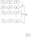
- Fig. 6 shows yet another system according to the present invention that comprises a plurality of physical noise sources (PNS), each followed by a spectrum-shaping filter (SSF) and a zero-crossing detector (ZCD).
- PPS physical noise sources
- SSF spectrum-shaping filter
- ZCD zero-crossing detector
- the binary waveforms obtained at the outputs of the zero-crossing detectors (ZCD) are then fed to a suitable multi-input-single-output combiner (MIC) that processes those waveforms in such a manner that their respective zero crossings are, at least partly, preserved.
- a random binary waveform (RBM) is obtained at the output of the combiner (MIC).
- Figure 6 differs from the arrangement shown in Figure 4 in that the noise signals are converted into binary signals, by the zero-crossing detectors (ZCD), before being combined.
- ZCD zero-crossing detectors
- Fig. 7 shows a specific example of the system of Fig. 6 where the combiner (MIC) is formed by a plurality of suitably connected Exclusive-OR logic gates (XOR). These gates, as is well known, perform a binary multiplying operation.
- MIC combiner
- XOR Exclusive-OR logic gates
- Figure 7 represents a preferred embodiment of the invention, assuming that the number of physical noise sources is equal to four.
- the rms bandwidth measured in Hertz (i.e., B s /2 ⁇ ) of the output of each noise source (PNS) is equal to 25 MHz.
- PPS noise source
- zero-crossing detectors and Exclusive-OR gates have infinitely fast responses.
- the half-height width of the correlation function of a binary waveform obtained at the output of any of the zero-crossing detectors is equal to 10.6 ns.
- the half-height width of the correlation function of the resulting binary waveform obtained at the output of the system is equal to 3.2 ns.
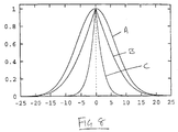
- Fig. 8 shows at A the auto-correlation function of the noise signal produced by a single physical noise source (PNS).
- PPS physical noise source
- ZCD zero-crossing detector
- C shows the auto-correlation function of the random binary waveform at the output of the embodiment of Figure 7, obtained by combining four uncorrelated binary waveforms. It will be seen that the correlation function C is much sharper than either of the functions A and B.
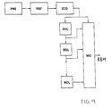
- Fig. 9 shows yet another system according to the present invention that comprises a single physical noise source (PNS) followed by a spectrum-shaping filter (SSF) and a zero-crossing detector (ZCD), a plurality of binary delay lines (BDL) and a suitable multi-input-single-output combiner (MIC) that processes the waveforms in such a manner that their respective zero crossings are, at least partly, preserved.
- PPS physical noise source
- SSF spectrum-shaping filter
- ZCD zero-crossing detector
- BDL binary delay lines
- MIC multi-input-single-output combiner
- Fig. 10 shows a specific example of the system shown in Fig. 9 where the combiner (MIC) is formed by a plurality of suitably connected Exclusive-OR logic gates (XOR).
- MIC combiner
- XOR Exclusive-OR logic gates
- Figure 11 shows another embodiment of the present invention, in which the output of a physical noise source (PNS) is applied to three level detectors (LD), each of which is arranged to change the state of its output when the signal from the noise source crosses a respective threshold level T1, T2 or T3.
- the outputs of the level detectors (LD) are combined by Exclusive-OR (XOR) circuits, as in the embodiment of Figure 10, to produce the resultant random binary waveform (RBM).
- the threshold levels T1, T2 and T3 are separated sufficiently to avoid significant correlation between the outputs of the level detectors (LD).
- level detectors which operate using different threshold levels
- level detectors with a common threshold level, such as zero-crossing detectors, if varying amounts of DC shift are applied to the output of the physical noise source before the respective level detection operations.
- PPS physical noise sources
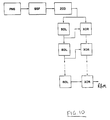
- Fig. 12 is a functional block diagram of another random binary waveform generator representing another preferred embodiment of the present invention.
- the system consists of four channels; each of three identical channels comprises a wideband physical noise source (PNS), a spectrum-shaping filter (SSF) and a zero-crossing detector (ZCD).
- PPS physical noise source
- SSF spectrum-shaping filter
- ZCD zero-crossing detector
- the fourth channel comprises a pseudo-random binary sequence generator (PRBS) driven by a clock unit (CLK) whose frequency may be constant or may vary.
- PRBS pseudo-random binary sequence generator
- CLK clock unit
- PRBS pseudo-random binary sequence generator
- a random binary waveform is obtained at the output of the last gate (XOR) of the cascade.
- the rms bandwidth measured in Hertz (i.e., B s /2 ⁇ ) is equal to 15 MHz.
- the pseudo-random binary sequence generator PRBS
- PRBS pseudo-random binary sequence generator
- the pseudo-random binary sequence generator consists of seven stages with a suitable feedback to obtain a sequence of length 127.
- the half- height width of the correlation function of a binary waveform obtained at the output of any of the zero-crossing detectors is equal to 17.6 ns.
- the half-height width of the correlation function of the resulting binary waveform obtained at the output of the system is equal to 5.2 ns.
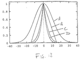
- Fig. 13 shows at A the auto-correlation function of the output signal produced by a physical noise source (PNS) of the embodiment of Figure 12.
- B represents the correlation function for the pseudo-random binary sequence (PRBS).
- C is the correlation function for the binary waveform obtained by combining the three uncorrelated binary waveforms derived from the physical noise sources (PNS).
- D is the correlation function for the output of the Figure 12 embodiment, which is produced by combining the three uncorrelated binary waveforms from the physical noise sources with the output of the pseudo-random binary sequence (PRBS).
- the correlation function for the output of a physical noise source exhibits tails which extend to plus and minus infinity. This also applies to the binary waveform derived therefrom, and to the combination of the binary waveforms derived from the physical noise sources (PNS).
- the correlation function for the pseudo-random binary sequence exhibits defined upper and lower temporal limits (within the range shown in Figure 13). This therefore also applies to the correlation function D for the output of the Figure 12 embodiment, because this combines the binary waveforms derived from the physical noise sources (PNS) with the pseudo-random binary sequence (PRBS) by Exclusive-OR'ing. This can have significant benefits, for example when the random binary waveform (RBM) is used for modulating carrier signals in radar or similar applications, because placing limits on the range of the auto-correlation function aids in the design of the system.
- RBM random binary waveform
- the invention thus provides a way of obtaining a random binary waveform with a sharp correlation function. This is achieved in the preferred embodiments by generating Gaussian signals and combining them in a nonlinear manner in order obtain a non-Gaussian signal which is used to produce the random binary waveform.
- Gaussian signals and combining them in a nonlinear manner in order obtain a non-Gaussian signal which is used to produce the random binary waveform.
- Various modifications are possible.
- the various features disclosed in respect of specific embodiments, particularly the techniques used for producing the preliminary signals which are then combined, can also be used in the other embodiments.
- a random binary waveform generator in accordance with the present invention is particularly suited for use in a time delay determination system according to International Patent Application No. WO 00/39643, filed 24 December 1999, the contents of which are incorporated herein by reference.
Abstract
Description
- This invention relates to a method and apparatus for generating random signals, and particularly but not exclusively random binary waveforms.
- Random binary waveforms with specific correlation properties are required for ranging and other applications, especially in radar systems. It is particularly desirable to provide random binary waveforms with maximum unpredictability, hence with low probability of intercept, and also resistant to intelligent jamming. Furthermore, such random binary waveforms are also useful for applications in multi-user environments where many similar or disparate systems operate in the same geographical region and those systems share, at least partly, the same wide frequency band.
- The generation of binary waveforms with specified correlation properties is of considerable practical interest in the field of radar and communications. For example, in low probability of intercept (LPI) radar the phase of the coherent carrier is modulated by a pseudo-random binary waveform to spread the spectrum of the transmitted signal. In some applications, such as collision avoidance/obstacle detection, altimetry, autonomous navigation etc., many similar radar systems should be capable of operating in the same region and sharing the same wide frequency band. To avoid mutual interference, each system should use a distinct signal, preferably orthogonal to the signals employed by all other systems. Therefore, the successful use of coded-waveform radar in a multi-user environment depends on the availability of large families of waveforms, each with specified correlation properties and low cross correlation values.
- An important class of synchronous binary waveforms can be obtained from suitably constructed binary sequences, such as pseudo-random binary sequences. However, when the number and type of systems (co-operating or unco-operating) sharing the same frequency band is unknown and often cannot even be predicted, it is not possible to assign a distinct binary sequence to each of them. It is also difficult to construct large sets of long pseudo-random sequences that provide a significant improvement over purely random sequences.
- The above problems can be avoided, or at least alleviated, when asynchronous random binary waveforms are used. In dense signal environments asynchronous waveforms are known to be superior to synchronous ones as a result of the additional randomisation of the zero crossing time instants. Because purely random binary waveforms exhibit maximum unpredictability, they are less vulnerable to intercept and intelligent jamming.
- One convenient and inexpensive method to generate a random binary waveform is based on level crossings of a random signal generated by a physical noise source. Fig. 1 shows an example of a generator of a random binary waveform. The generator comprises a physical noise source (PNS) and a zero-crossing detector (ZCD) which can be a comparator or a hard limiter. Fig. 2 shows a typical realisation of a noise signal s(t) and a random binary waveform b(t) obtained from that noise signal and defined by zero crossings of that signal. Each zero crossing results in an event (an edge) in the binary waveform b(t), the events occurring aperiodically and unpredictably.
- In radar and also other applications the shape of the correlation function of a binary waveform is of primary importance. The ideal correlation function would have the form of an impulse (Dirac delta) function. In practice, the correlation function of a 'good' binary waveform should attempt to approximate in some way this ideal shape. Fig. 3 shows the shape of the correlation function Rb(τ) of a random binary waveform b(t) ideal for ranging applications.
- In practice it is relatively easy to generate noise signals with a Gaussian distribution, e.g., by exploiting thermal noise. When an underlying noise signal s(t) has a Gaussian distribution, the correlation function Rb(τ) of a binary waveform b(t) obtained from zero crossings of the signal s(t) can be determined from Van Vleck's formula
- It is known that the correlation function of a random binary waveform, not necessarily obtained from a Gaussian noise signal, has a cusp at the origin and that this cusp is sharper when the average number, N0, of zero crossings in unit time is larger. When an underlying noise signal s(t) has a Gaussian distribution, the average number, N0, of zero crossings in unit time can be determined from Rice's formula:
- It would, accordingly, be desirable to provide an apparatus and method for the generation of a random binary waveform with an extremely narrow correlation function suitable for ranging and other applications.
- It would also be desirable to provide an apparatus and method for the generation of a random binary waveform intended for application in multi-user environments.
- It would be further desirable to provide an apparatus and method for the generation of a random binary waveform resistant to deliberate intelligent jamming.
- It would additionally be desirable to provide an apparatus and method for the generation of a random binary waveform with low probability of intercept.
- According to one aspect of the invention there is provided a method of generating a resultant signal containing time marks, referred to herein as events, which occur at random intervals, the method comprising generating a plurality of preliminary signals each containing events occurring at random intervals and combining the preliminary signals. The combining is performed in such a way as to preserve, at least substantially, the events therein. In the embodiments described below, the combining is performed by multiplying (in either the analog or digital domain) and results in the interspersing of the events in the resultant signal. At least one of the preliminary signals contains events occurring asynchronously (i.e. without being clocked, and indeed the system of the present invention does not depend on the use of a clock).
- Throughout the present specification, including the claims, except where the context indicates otherwise, the term "random" is intended to cover not only purely random, non-deterministically generated signals, but also pseudo-random, deterministic signals such as the output of a shift register arrangement provided with a feedback circuit as used in the prior art to generate pseudo-random binary signals, and chaotic signals. Preferably, however, at least one of the preliminary signals is purely random (non-deterministic), or possibly chaotic, and contains aperiodic events.
- According to a further aspect of the invention, a method of generating a random signal comprises producing a plurality of preliminary signals of random amplitude which can be level-detected to generate a binary waveform with transitions at random intervals, and combining the signals either before or after level-detection in order to generate a resultant random binary output. The combining of the signals is performed in such a manner that the events represented by the transitions are, at least partly, preserved. The preliminary signals are, at least partly, uncorrelated.
- Some of the signals or binary waveforms to be combined can be obtained from a single signal or a single binary waveform by utilising a plurality of suitably time-delayed replicas of this signal or waveform. The time-delayed replicas should be, at least partly, uncorrelated with each other, and to this end the time delay used to form each replica preferably has a value which corresponds to a substantially zero level of the correlation function of the original signal.
- In another embodiment, the plurality of preliminary signals are derived from a common physical noise source which produces an output of random amplitude. Each preliminary signal is derived by level-detection, at a respective, different level, of the output of the physical noise source. The levels are preferably separated sufficiently so as to avoid significant correlation between the preliminary signals.
- Arrangements embodying the invention will now be described by way of example with reference to the accompanying drawings, in which like reference symbols represent like integers, and in which:
- Figure 1 shows an example of a system for generating a random binary waveform in accordance with the prior art;
- Figure 2 shows a typical realisation of a noise signal s(t) and a random binary waveform b(t) obtained from that noise signal and defined by zero-level crossings of that signal;
- Figure 3 shows the shape of the correlation function Rb(τ) of a random binary waveform b(t) ideal for ranging applications;
- Figures 4 to 6 are block diagrams of, respectively, first to third embodiments of a system according to the present invention;
- Figure 7 is a block diagram of a specific example of the embodiment shown in Fig. 6;
- Figure 8 shows the correlation function of a random binary waveform generated by the embodiment of Figure 7;
- Figure 9 is a block diagram of yet another embodiment of a system according to the present invention;
- Figure 10 is a block diagram of a specific example of the embodiment shown in Fig. 8;
- Figure 11 is a block diagram of another embodiment of the present invention;
- Figure 12 is a block diagram of a further embodiment of the present invention; and
- Figure 13 shows the correlation function of a random binary waveform generated by the embodiment of Figure 11.
-
- Fig. 4 shows a system according to the present invention that comprises a plurality of wideband physical noise sources (PNS) followed by spectrum-shaping filters (SSF), a plurality of analog multipliers (AM) or balanced modulators, and a single zero-crossing detector (ZCD) which can be a comparator or a hard limiter. A random binary waveform (RBM) useful for modulating a carrier prior to transmission in radar and communications applications is obtained at the output of the zero-crossing detector (ZCD).
- Preferably the physical noise source (PNS) is a Zener diode used as per se known in the prior art, which provides an output having a Gaussian voltage distribution.
- Preferably the zero-crossing detector (ZCD) is a fast comparator with a zero threshold.
- In operation, each physical noise source (PNS) produces a waveform similar to that shown at s(t) in Figure 2, the waveforms being uncorrelated. Each waveform is filtered by a respective spectrum-shaping filter (SSF) which may have an approximately Gaussian power transfer function |H(ω)|2 of the form:
- The advantage of such a characteristic is that the Fourier transform exhibits a monotonic decline to zero level, and thus exhibits no undershoot or ringing. Other types of transfer functions, preferably exhibiting similar advantages, could alternatively be used. It is possible to use filters with identical characteristics for the respective channels (noise sources), or if desired different characteristics could be selected, or indeed in some circumstances the filters could be omitted.
- The outputs of the first two filters are multiplied by the first of the analog multipliers (AM), the output of which is multiplied by the output from the third filter (SSF) in the next analog multiplier (AM), etc. The output from the final analog multiplier (AM) is also a waveform generally similar to s(t) in Figure 2 except that there is a substantially greater number of zero-crossings. In effect, the number of zero-crossings is the sum of the number in each of the respective signals from the noise sources (PNS). This output signal is delivered to the zero-crossing detector (ZCD) to produce the random binary waveform (RBM), similar to that shown at b(t) in Figure 2 but again containing a substantially greater number of transitions.
- As a result of this arrangement, assuming that there are n channels, the number of zero-crossings in unit time as compared with a single noise source is increased by a factor of n, thus producing a substantially sharper correlation function and therefore a signal which is much better suited to ranging applications, for example. The rms bandwidth, however, is increased by only √n.
- Although increasing the number of channels also increases the sharpness of the correlation function, the extent of the improvement reduces with an increase in the number of channels. By way of example, assume that each spectrum-shaping filter has an approximately Gaussian power transfer function |H(ω)|2 of the form:
Number of identical channels combined Half-height width of the correlation function (normalised units) 1 1.00 2 0.56 3 0.39 4 0.30 5 0.25 6 0.21 7 0.18 8 0.16 - In practical embodiments, it is likely that the optimum number of channels would be three or four, as the cost of increasing the number of channels is unlikely to justify the added improvement in the signal.
- In the embodiments to be described below, similar considerations apply to the preferred nature of the physical noise sources (PNS), the spectrum-shaping filters (SSF) and the zero-crossing detector (ZCD), and to the number of channels.
- Fig. 5 shows another system according to the present invention that comprises a single wideband physical noise source (PNS) followed by a spectrum-shaping filter (SSF), a plurality of analog delay lines (DL), a plurality of analog multipliers (AM) or balanced modulators, and a single zero-crossing detector (ZCD) which can be a comparator or a hard limiter. A random binary waveform (RMB) is obtained at the output of the zero-crossing detector (ZCD).
- Figure 5 differs from the arrangement shown in Figure 4 by virtue of the fact that, instead of using independent noise sources (PNS), a single noise source (PNS) is used, the remainder of the preliminary noise signals being produced by time-delayed replicas of the original noise signal, the delays being produced by the analog delay lines (DL). In order to ensure that the noise signals delivered to the analog multipliers (AM) are substantially uncorrelated, each delay line imparts a sufficiently long delay; the delay is such that the correlation function of the signal produced is substantially zero at that delay point. The delays may be different from each other, and/or may vary with time.
- Fig. 6 shows yet another system according to the present invention that comprises a plurality of physical noise sources (PNS), each followed by a spectrum-shaping filter (SSF) and a zero-crossing detector (ZCD). The binary waveforms obtained at the outputs of the zero-crossing detectors (ZCD) are then fed to a suitable multi-input-single-output combiner (MIC) that processes those waveforms in such a manner that their respective zero crossings are, at least partly, preserved. A random binary waveform (RBM) is obtained at the output of the combiner (MIC).
- Figure 6 differs from the arrangement shown in Figure 4 in that the noise signals are converted into binary signals, by the zero-crossing detectors (ZCD), before being combined.
- Fig. 7 shows a specific example of the system of Fig. 6 where the combiner (MIC) is formed by a plurality of suitably connected Exclusive-OR logic gates (XOR). These gates, as is well known, perform a binary multiplying operation.
- Figure 7 represents a preferred embodiment of the invention, assuming that the number of physical noise sources is equal to four. In one particular example of this embodiment, assume that the rms bandwidth measured in Hertz (i.e., Bs/2π) of the output of each noise source (PNS) is equal to 25 MHz. For the purpose of this analysis it is also assumed that zero-crossing detectors and Exclusive-OR gates have infinitely fast responses. The half-height width of the correlation function of a binary waveform obtained at the output of any of the zero-crossing detectors is equal to 10.6 ns. However, the half-height width of the correlation function of the resulting binary waveform obtained at the output of the system is equal to 3.2 ns.
- Fig. 8 shows at A the auto-correlation function of the noise signal produced by a single physical noise source (PNS). B represents the correlation function of the binary waveform at the output of the zero-crossing detector (ZCD). C shows the auto-correlation function of the random binary waveform at the output of the embodiment of Figure 7, obtained by combining four uncorrelated binary waveforms. It will be seen that the correlation function C is much sharper than either of the functions A and B.
- Fig. 9 shows yet another system according to the present invention that comprises a single physical noise source (PNS) followed by a spectrum-shaping filter (SSF) and a zero-crossing detector (ZCD), a plurality of binary delay lines (BDL) and a suitable multi-input-single-output combiner (MIC) that processes the waveforms in such a manner that their respective zero crossings are, at least partly, preserved. A random binary waveform (RBM) is obtained at the output of a combiner (MIC).
- This is thus similar to the embodiment of Figure 6, except (analogously to Figure 5) the separate noise sources are replaced by delay lines.
- Fig. 10 shows a specific example of the system shown in Fig. 9 where the combiner (MIC) is formed by a plurality of suitably connected Exclusive-OR logic gates (XOR).
- Figure 11 shows another embodiment of the present invention, in which the output of a physical noise source (PNS) is applied to three level detectors (LD), each of which is arranged to change the state of its output when the signal from the noise source crosses a respective threshold level T1, T2 or T3. The outputs of the level detectors (LD) are combined by Exclusive-OR (XOR) circuits, as in the embodiment of Figure 10, to produce the resultant random binary waveform (RBM). The threshold levels T1, T2 and T3 are separated sufficiently to avoid significant correlation between the outputs of the level detectors (LD). Of course, instead of having level detectors which operate using different threshold levels, it would be possible to use level detectors with a common threshold level, such as zero-crossing detectors, if varying amounts of DC shift are applied to the output of the physical noise source before the respective level detection operations.
- Some of the physical noise sources (PNS) referred to above may be replaced by other physical sources utilised to generate chaotic signals, and some, but not all, by other deterministic pseudo-random sources.
- Fig. 12 is a functional block diagram of another random binary waveform generator representing another preferred embodiment of the present invention. The system consists of four channels; each of three identical channels comprises a wideband physical noise source (PNS), a spectrum-shaping filter (SSF) and a zero-crossing detector (ZCD).
- The fourth channel comprises a pseudo-random binary sequence generator (PRBS) driven by a clock unit (CLK) whose frequency may be constant or may vary. Preferably the pseudo-random binary sequence generator (PRBS) is a shift register with a feedback circuit constructed in accordance with the prior art. A random binary waveform is obtained at the output of the last gate (XOR) of the cascade. Although the correlation function of a pseudo-random binary sequence is periodic, the correlation function of the resulting random binary waveform is aperiodic.
- In one example of the arrangement of Figure 12, assume that the rms bandwidth measured in Hertz (i.e., Bs/2π) is equal to 15 MHz. For the purpose of this analysis it is assumed that zero-crossing detectors and Exclusive-OR gates have infinitely fast responses. It is also assumed that the pseudo-random binary sequence generator (PRBS) is driven by a clock with frequency of 66 MHz. The pseudo-random binary sequence generator (PRBS) consists of seven stages with a suitable feedback to obtain a sequence of length 127. The half- height width of the correlation function of a binary waveform obtained at the output of any of the zero-crossing detectors is equal to 17.6 ns. However, the half-height width of the correlation function of the resulting binary waveform obtained at the output of the system is equal to 5.2 ns.
- Fig. 13 shows at A the auto-correlation function of the output signal produced by a physical noise source (PNS) of the embodiment of Figure 12. B represents the correlation function for the pseudo-random binary sequence (PRBS). C is the correlation function for the binary waveform obtained by combining the three uncorrelated binary waveforms derived from the physical noise sources (PNS). D is the correlation function for the output of the Figure 12 embodiment, which is produced by combining the three uncorrelated binary waveforms from the physical noise sources with the output of the pseudo-random binary sequence (PRBS).
- The correlation function for the output of a physical noise source (PNS) exhibits tails which extend to plus and minus infinity. This also applies to the binary waveform derived therefrom, and to the combination of the binary waveforms derived from the physical noise sources (PNS). However, the correlation function for the pseudo-random binary sequence (PRBS) exhibits defined upper and lower temporal limits (within the range shown in Figure 13). This therefore also applies to the correlation function D for the output of the Figure 12 embodiment, because this combines the binary waveforms derived from the physical noise sources (PNS) with the pseudo-random binary sequence (PRBS) by Exclusive-OR'ing. This can have significant benefits, for example when the random binary waveform (RBM) is used for modulating carrier signals in radar or similar applications, because placing limits on the range of the auto-correlation function aids in the design of the system.
- The invention thus provides a way of obtaining a random binary waveform with a sharp correlation function. This is achieved in the preferred embodiments by generating Gaussian signals and combining them in a nonlinear manner in order obtain a non-Gaussian signal which is used to produce the random binary waveform. Various modifications are possible. The various features disclosed in respect of specific embodiments, particularly the techniques used for producing the preliminary signals which are then combined, can also be used in the other embodiments.
- A random binary waveform generator in accordance with the present invention is particularly suited for use in a time delay determination system according to International Patent Application No. WO 00/39643, filed 24 December 1999, the contents of which are incorporated herein by reference.
Claims (16)
- A method of generating a random binary waveform containing events which occur at random intervals, the method comprising deriving, from a physical noise source, a first preliminary signal containing events occurring asynchronously and at random intervals and multiplying the first preliminary signal with at least one further preliminary signal containing further events occurring at random intervals so as to intersperse the events.
- A method as claimed in claim 1, wherein the first preliminary signal is derived by level-detecting a random amplitude analog signal produced by the physical noise source.
- A method as claimed in claim 2, wherein at least one further preliminary signal is derived by level-detecting said random amplitude analog signal.
- A method as claimed in any preceding claim, wherein the preliminary signals are combined by analog multiplication.
- A method as claimed in any one of claims 1 to 3, wherein the preliminary signals are binary signals which are combined by binary multiplication.
- A method as claimed in claim 5, wherein the preliminary signals are combined by an Exclusive-OR operation.
- A method as claimed in any preceding claim, wherein the physical noise source produces a non-deterministic output.
- A method as claimed in one of claims 1 to 6, wherein the physical noise source produces a chaotic output.
- A method as claimed in any preceding claim, wherein at least one further preliminary signal is a pseudo-random binary sequence.
- A method as claimed in any preceding claim, wherein at least one further preliminary signal is a chaotic signal.
- A method as claimed in any preceding claim, wherein at least one of the preliminary signals is a time-delayed version of another of the preliminary signals.
- A method as claimed in claim 11, wherein the time delay has a value such that the correlation function of said one preliminary signal for that value is substantially zero.
- A method as claimed in any preceding claim, including producing a signal from said physical noise source and applying a spectral filter to the signal in order to obtain said first preliminary signal.
- A method as claimed in any preceding claim, wherein the number of preliminary signals is equal to 3 or 4.
- A method of detecting objects comprising measuring the delay between transmission of a signal modulated by a random binary waveform generated by a method according to any preceding claim and receipt of the reflection of the signal from the object.
- Apparatus for generating a random binary waveform containing events which occur at random intervals, the apparatus comprising:a physical noise source producing a random output signal;means for deriving, from said random output signal, a first preliminary signal containing events occurring asynchronously at random intervals;means for providing at least one further preliminary signal containing further events occurring at random intervals; andmeans for multiplying the first preliminary signal and said at least one further preliminary signal so as to produce a random binary waveform in which said events are interspersed.
Applications Claiming Priority (2)
| Application Number | Priority Date | Filing Date | Title |
|---|---|---|---|
| GB9918518 | 1999-08-05 | ||
| GB9918518A GB2353155A (en) | 1999-08-05 | 1999-08-05 | A random binary signal generator with a narrowed autocorrelation function |
Publications (3)
| Publication Number | Publication Date |
|---|---|
| EP1075084A2 true EP1075084A2 (en) | 2001-02-07 |
| EP1075084A3 EP1075084A3 (en) | 2003-05-02 |
| EP1075084B1 EP1075084B1 (en) | 2008-01-02 |
Family
ID=10858669
Family Applications (1)
| Application Number | Title | Priority Date | Filing Date |
|---|---|---|---|
| EP00306612A Expired - Lifetime EP1075084B1 (en) | 1999-08-05 | 2000-08-03 | Method and apparatus for generating random signals |
Country Status (5)
| Country | Link |
|---|---|
| US (1) | US7145933B1 (en) |
| EP (1) | EP1075084B1 (en) |
| JP (1) | JP2001100980A (en) |
| DE (1) | DE60037621T2 (en) |
| GB (1) | GB2353155A (en) |
Cited By (4)
| Publication number | Priority date | Publication date | Assignee | Title |
|---|---|---|---|---|
| US6771104B2 (en) | 2002-07-25 | 2004-08-03 | Koninklijke Philips Electronics N.V. | Switching electronic circuit for random number generation |
| US7047262B2 (en) | 2002-08-21 | 2006-05-16 | Koninklijke Philips Electronics N.V. | Entropy estimation and decimation for improving the randomness of true random number generation |
| US7124155B2 (en) | 2002-07-25 | 2006-10-17 | Koninklijke Philips Electronics N.V. | Latching electronic circuit for random number generation |
| WO2008141819A2 (en) * | 2007-05-22 | 2008-11-27 | Atmel Germany Gmbh | Apparatus and method for generating a random number |
Families Citing this family (28)
| Publication number | Priority date | Publication date | Assignee | Title |
|---|---|---|---|---|
| JP3500580B2 (en) * | 2001-08-15 | 2004-02-23 | 財団法人資源探査用観測システム研究開発機構 | Radar equipment |
| WO2006054476A1 (en) * | 2004-11-18 | 2006-05-26 | Niigata Tlo Corporation | Random number generating method and device |
| USRE47633E1 (en) | 2005-06-22 | 2019-10-01 | Odyssey Wireless Inc. | Systems/methods of conducting a financial transaction using a smartphone |
| US8233554B2 (en) | 2010-03-29 | 2012-07-31 | Eices Research, Inc. | Increased capacity communications for OFDM-based wireless communications systems/methods/devices |
| US7876845B2 (en) * | 2005-06-22 | 2011-01-25 | Eices Research, Inc. | Wireless communications systems and/or methods providing low interference, high privacy and/or cognitive flexibility |
| US8670493B2 (en) | 2005-06-22 | 2014-03-11 | Eices Research, Inc. | Systems and/or methods of increased privacy wireless communications |
| US8738675B2 (en) * | 2006-08-03 | 2014-05-27 | Salih Ergun | Random numbers generation using continuous-time chaos |
| JP2008242832A (en) | 2007-03-27 | 2008-10-09 | Toshiba Corp | Random number generation device |
| JP4950924B2 (en) * | 2008-03-19 | 2012-06-13 | 日本電信電話株式会社 | Chaos laser oscillator, ultra-high speed physical random number generator and method using the same, program, and recording medium |
| US9374746B1 (en) | 2008-07-07 | 2016-06-21 | Odyssey Wireless, Inc. | Systems/methods of spatial multiplexing |
| US8742814B2 (en) | 2009-07-15 | 2014-06-03 | Yehuda Binder | Sequentially operated modules |
| US8602833B2 (en) | 2009-08-06 | 2013-12-10 | May Patents Ltd. | Puzzle with conductive path |
| US9806790B2 (en) | 2010-03-29 | 2017-10-31 | Odyssey Wireless, Inc. | Systems/methods of spectrally efficient communications |
| IL210169A0 (en) | 2010-12-22 | 2011-03-31 | Yehuda Binder | System and method for routing-based internet security |
| US20120244969A1 (en) | 2011-03-25 | 2012-09-27 | May Patents Ltd. | System and Method for a Motion Sensing Device |
| US9019718B2 (en) | 2011-08-26 | 2015-04-28 | Littlebits Electronics Inc. | Modular electronic building systems with magnetic interconnections and methods of using the same |
| US11330714B2 (en) | 2011-08-26 | 2022-05-10 | Sphero, Inc. | Modular electronic building systems with magnetic interconnections and methods of using the same |
| US9597607B2 (en) | 2011-08-26 | 2017-03-21 | Littlebits Electronics Inc. | Modular electronic building systems with magnetic interconnections and methods of using the same |
| US20130201316A1 (en) | 2012-01-09 | 2013-08-08 | May Patents Ltd. | System and method for server based control |
| WO2013175269A1 (en) | 2012-05-24 | 2013-11-28 | May Patents Ltd. | System and method for a motion sensing device |
| RU2549524C1 (en) * | 2014-06-26 | 2015-04-27 | Федеральное государственное бюджетное образовательное учреждение высшего профессионального образования "Казанский национальный исследовательский технический университет им. А.Н. Туполева-КАИ" (КНИТУ-КАИ) | Generator of nonlinear pseudorandom sequences |
| US11190374B2 (en) | 2017-08-28 | 2021-11-30 | Bright Data Ltd. | System and method for improving content fetching by selecting tunnel devices |
| LT3472717T (en) | 2017-08-28 | 2021-01-11 | Luminati Networks Ltd. | Method for improving content fetching by selecting tunnel devices |
| US11055065B2 (en) * | 2018-04-18 | 2021-07-06 | Ememory Technology Inc. | PUF-based true random number generation system |
| US20210138232A1 (en) | 2018-08-14 | 2021-05-13 | Neurotrigger Ltd. | Method and apparatus for transcutaneous facial nerve stimulation and applications thereof |
| EP3780557B1 (en) | 2019-02-25 | 2023-02-15 | Bright Data Ltd. | System and method for url fetching retry mechanism |
| US11616844B2 (en) | 2019-03-14 | 2023-03-28 | Sphero, Inc. | Modular electronic and digital building systems and methods of using the same |
| EP4030318A1 (en) | 2019-04-02 | 2022-07-20 | Bright Data Ltd. | System and method for managing non-direct url fetching service |
Citations (5)
| Publication number | Priority date | Publication date | Assignee | Title |
|---|---|---|---|---|
| FR1226403A (en) * | 1954-06-03 | 1960-07-11 | Electronique & Automatisme Sa | Advanced electrical signal generators |
| FR76933E (en) * | 1960-01-15 | 1961-12-15 | Electronique & Automatisme Sa | Advanced electrical signal generators |
| EP0293287A1 (en) * | 1987-05-26 | 1988-11-30 | Thomson-Csf | Spread spectrum phase demodulator test system |
| EP0488739A1 (en) * | 1990-11-28 | 1992-06-03 | NOVATEL COMMUNICATIONS Ltd. | Multi-channel digital receiver for global positioning system |
| WO2000054406A1 (en) * | 1999-03-11 | 2000-09-14 | Richard Vogts | Random signal generator and method for generating a random signals |
Family Cites Families (14)
| Publication number | Priority date | Publication date | Assignee | Title |
|---|---|---|---|---|
| CA923603A (en) * | 1970-09-23 | 1973-03-27 | Canadian Marconi Company | Circuit for avoiding false lock |
| US4429310A (en) * | 1981-04-22 | 1984-01-31 | Sperry Corporation | Random binary waveform encoded ranging apparatus |
| US4513386A (en) * | 1982-11-18 | 1985-04-23 | Ncr Corporation | Random binary bit signal generator |
| US4617530A (en) * | 1985-06-17 | 1986-10-14 | The United States Of America As Represented By The Secretary Of The Navy | Pseudo-random noise generator |
| US4905176A (en) * | 1988-10-28 | 1990-02-27 | International Business Machines Corporation | Random number generator circuit |
| US5153532A (en) * | 1989-05-24 | 1992-10-06 | Honeywell Inc. | Noise generator using combined outputs of two pseudo-random sequence generators |
| US4928310A (en) * | 1989-07-17 | 1990-05-22 | Westinghouse Electric Corp. | Pseudorandom pulse code generators using electro-optical XOR gates |
| WO1991010182A1 (en) * | 1989-12-21 | 1991-07-11 | Bell Communications Research, Inc. | Generator of multiple uncorrelated noise sources |
| EP0825737B1 (en) * | 1996-03-05 | 2007-05-02 | NTT DoCoMo, Inc. | Signal transmission method, transmitter and receiver in mobile communication system |
| WO1998033075A2 (en) * | 1997-01-13 | 1998-07-30 | Sage Technology, Incorporated | Random number generator based on directional randomness associated with naturally occurring random events, and method therefor |
| IT1293059B1 (en) * | 1997-06-24 | 1999-02-11 | Space Engineering Spa | DIGITAL BI-STATIC RADAR WITH EXPANDED SPECTRUM |
| JP2942923B2 (en) * | 1997-11-27 | 1999-08-30 | 株式会社ジーデイーエス | Random pulse type radar device |
| US6275959B1 (en) * | 1998-07-20 | 2001-08-14 | Lucent Technologies Inc. | Adaptive threshold control circuit and method within high speed receivers |
| GB9828693D0 (en) * | 1998-12-24 | 1999-02-17 | Mitsubishi Electric Inf Tech | Time delay determination |
-
1999
- 1999-08-05 GB GB9918518A patent/GB2353155A/en not_active Withdrawn
-
2000
- 2000-08-03 EP EP00306612A patent/EP1075084B1/en not_active Expired - Lifetime
- 2000-08-03 DE DE60037621T patent/DE60037621T2/en not_active Expired - Lifetime
- 2000-08-04 JP JP2000236764A patent/JP2001100980A/en active Pending
- 2000-08-04 US US09/633,275 patent/US7145933B1/en not_active Expired - Fee Related
Patent Citations (5)
| Publication number | Priority date | Publication date | Assignee | Title |
|---|---|---|---|---|
| FR1226403A (en) * | 1954-06-03 | 1960-07-11 | Electronique & Automatisme Sa | Advanced electrical signal generators |
| FR76933E (en) * | 1960-01-15 | 1961-12-15 | Electronique & Automatisme Sa | Advanced electrical signal generators |
| EP0293287A1 (en) * | 1987-05-26 | 1988-11-30 | Thomson-Csf | Spread spectrum phase demodulator test system |
| EP0488739A1 (en) * | 1990-11-28 | 1992-06-03 | NOVATEL COMMUNICATIONS Ltd. | Multi-channel digital receiver for global positioning system |
| WO2000054406A1 (en) * | 1999-03-11 | 2000-09-14 | Richard Vogts | Random signal generator and method for generating a random signals |
Non-Patent Citations (1)
| Title |
|---|
| "Alpha-particle random number generator" IBM TECHNICAL DISCLOSURE BULLETIN, IBM CORP. NEW YORK, US, vol. 30, no. 9, February 1988 (1988-02), pages 337-339, XP002140868 ISSN: 0018-8689 * |
Cited By (7)
| Publication number | Priority date | Publication date | Assignee | Title |
|---|---|---|---|---|
| US6771104B2 (en) | 2002-07-25 | 2004-08-03 | Koninklijke Philips Electronics N.V. | Switching electronic circuit for random number generation |
| US7124155B2 (en) | 2002-07-25 | 2006-10-17 | Koninklijke Philips Electronics N.V. | Latching electronic circuit for random number generation |
| US7047262B2 (en) | 2002-08-21 | 2006-05-16 | Koninklijke Philips Electronics N.V. | Entropy estimation and decimation for improving the randomness of true random number generation |
| WO2008141819A2 (en) * | 2007-05-22 | 2008-11-27 | Atmel Germany Gmbh | Apparatus and method for generating a random number |
| WO2008141819A3 (en) * | 2007-05-22 | 2009-04-16 | Atmel Germany Gmbh | Apparatus and method for generating a random number |
| US8244786B2 (en) | 2007-05-22 | 2012-08-14 | Atmel Corporation | Device and method for generating a random number |
| DE112008000057B4 (en) * | 2007-05-22 | 2013-11-14 | Atmel Corp. | Apparatus and method for generating a random number |
Also Published As
| Publication number | Publication date |
|---|---|
| EP1075084A3 (en) | 2003-05-02 |
| GB9918518D0 (en) | 1999-10-06 |
| DE60037621D1 (en) | 2008-02-14 |
| JP2001100980A (en) | 2001-04-13 |
| DE60037621T2 (en) | 2008-12-24 |
| GB2353155A (en) | 2001-02-14 |
| US7145933B1 (en) | 2006-12-05 |
| EP1075084B1 (en) | 2008-01-02 |
Similar Documents
| Publication | Publication Date | Title |
|---|---|---|
| US7145933B1 (en) | Method and apparatus for generating random signals | |
| Sturm et al. | A novel approach to OFDM radar processing | |
| US4730340A (en) | Programmable time invariant coherent spread symbol correlator | |
| US7903778B2 (en) | Low power, high resolution timing generator for ultra-wide bandwidth communication systems | |
| ZA200901119B (en) | A method for measuring the radial velocity of a target with a doppler radar | |
| Gao et al. | Piecewise LFM waveform for MIMO radar | |
| US8311074B2 (en) | Low power, high resolution timing generator for ultra-wide bandwidth communication systems | |
| Haderer et al. | A comparison of phase-coded CW radar modulation schemes for integrated radar sensors | |
| Cao et al. | Slow-time waveform design for MIMO GMTI radar using CAZAC sequences | |
| Dida et al. | Constant envelope chirped OFDM for power-efficient radar communication | |
| GB2401016A (en) | Apparatus for rapidly outputting a waveform template | |
| Pillai et al. | Reconstruction of constant envelope signals with given Fourier transform magnitude | |
| Zhao et al. | Design of unimodular sequence train with low central and recurrent autocorrelations | |
| US7423470B2 (en) | Pulse generator | |
| US4396894A (en) | Digital noise generating apparatus | |
| Skinner et al. | Matched FSK/PSK radar | |
| Srinivasu et al. | Performance evaluation of UWB waveforms in high-resolution radar | |
| Raghavendra et al. | Improvement in PMEPR reduction for OFDM radar signal using PTS algorithm | |
| Hekrdla et al. | Spectrally compact SFSK radar waveforms | |
| Jones et al. | Spectral notching via error reduction algorithm with relaxed papr constraint | |
| Kadlimatti | Good Code Sets via Coprime Powers | |
| Rawat et al. | Effectiveness of Pulse Compression Signal Processing Techniques of Radar | |
| RU2327288C1 (en) | Radio communication system with multiple access | |
| Szajnowski | A Class of Random Binary Waveforms With Impulse-Like Autocorrelation | |
| Heunisch et al. | A phase‐correlated duo‐binary waveform generation technique for millimeter‐wave radar pulses |
Legal Events
| Date | Code | Title | Description |
|---|---|---|---|
| PUAI | Public reference made under article 153(3) epc to a published international application that has entered the european phase |
Free format text: ORIGINAL CODE: 0009012 |
|
| AK | Designated contracting states |
Kind code of ref document: A2 Designated state(s): AT BE CH CY DE DK ES FI FR GB GR IE IT LI LU MC NL PT SE |
|
| AX | Request for extension of the european patent |
Free format text: AL;LT;LV;MK;RO;SI |
|
| PUAL | Search report despatched |
Free format text: ORIGINAL CODE: 0009013 |
|
| AK | Designated contracting states |
Designated state(s): AT BE CH CY DE DK ES FI FR GB GR IE IT LI LU MC NL PT SE |
|
| AX | Request for extension of the european patent |
Extension state: AL LT LV MK RO SI |
|
| 17P | Request for examination filed |
Effective date: 20031028 |
|
| AKX | Designation fees paid |
Designated state(s): AT BE CH LI |
|
| RBV | Designated contracting states (corrected) |
Designated state(s): DE FR GB |
|
| REG | Reference to a national code |
Ref country code: DE Ref legal event code: 8566 |
|
| RAP1 | Party data changed (applicant data changed or rights of an application transferred) |
Owner name: MITSUBISHI ELECTRIC INFORMATION TECHNOLOGY CENTRE Owner name: MITSUBISHI DENKI KABUSHIKI KAISHA |
|
| RAP1 | Party data changed (applicant data changed or rights of an application transferred) |
Owner name: MITSUBISHI ELECTRIC INFORMATION TECHNOLOGY CENTRE Owner name: MITSUBISHI DENKI KABUSHIKI KAISHA |
|
| 17Q | First examination report despatched |
Effective date: 20060720 |
|
| 17Q | First examination report despatched |
Effective date: 20060720 |
|
| GRAP | Despatch of communication of intention to grant a patent |
Free format text: ORIGINAL CODE: EPIDOSNIGR1 |
|
| GRAS | Grant fee paid |
Free format text: ORIGINAL CODE: EPIDOSNIGR3 |
|
| GRAA | (expected) grant |
Free format text: ORIGINAL CODE: 0009210 |
|
| AK | Designated contracting states |
Kind code of ref document: B1 Designated state(s): DE FR GB |
|
| REG | Reference to a national code |
Ref country code: GB Ref legal event code: FG4D |
|
| REF | Corresponds to: |
Ref document number: 60037621 Country of ref document: DE Date of ref document: 20080214 Kind code of ref document: P |
|
| ET | Fr: translation filed | ||
| PLBE | No opposition filed within time limit |
Free format text: ORIGINAL CODE: 0009261 |
|
| STAA | Information on the status of an ep patent application or granted ep patent |
Free format text: STATUS: NO OPPOSITION FILED WITHIN TIME LIMIT |
|
| 26N | No opposition filed |
Effective date: 20081003 |
|
| PGFP | Annual fee paid to national office [announced via postgrant information from national office to epo] |
Ref country code: DE Payment date: 20110727 Year of fee payment: 12 Ref country code: GB Payment date: 20110803 Year of fee payment: 12 Ref country code: FR Payment date: 20110818 Year of fee payment: 12 |
|
| GBPC | Gb: european patent ceased through non-payment of renewal fee |
Effective date: 20120803 |
|
| REG | Reference to a national code |
Ref country code: FR Ref legal event code: ST Effective date: 20130430 |
|
| PG25 | Lapsed in a contracting state [announced via postgrant information from national office to epo] |
Ref country code: DE Free format text: LAPSE BECAUSE OF NON-PAYMENT OF DUE FEES Effective date: 20130301 Ref country code: GB Free format text: LAPSE BECAUSE OF NON-PAYMENT OF DUE FEES Effective date: 20120803 |
|
| PG25 | Lapsed in a contracting state [announced via postgrant information from national office to epo] |
Ref country code: FR Free format text: LAPSE BECAUSE OF NON-PAYMENT OF DUE FEES Effective date: 20120831 |
|
| REG | Reference to a national code |
Ref country code: DE Ref legal event code: R119 Ref document number: 60037621 Country of ref document: DE Effective date: 20130301 |