EP1154585A1 - Receiver for a communication device for a multi-path radio channel - Google Patents
Receiver for a communication device for a multi-path radio channel Download PDFInfo
- Publication number
- EP1154585A1 EP1154585A1 EP00110027A EP00110027A EP1154585A1 EP 1154585 A1 EP1154585 A1 EP 1154585A1 EP 00110027 A EP00110027 A EP 00110027A EP 00110027 A EP00110027 A EP 00110027A EP 1154585 A1 EP1154585 A1 EP 1154585A1
- Authority
- EP
- European Patent Office
- Prior art keywords
- signals
- arrangement
- receiver
- receiver arrangement
- less
- Prior art date
- Legal status (The legal status is an assumption and is not a legal conclusion. Google has not performed a legal analysis and makes no representation as to the accuracy of the status listed.)
- Granted
Links
Images


Classifications
-
- H—ELECTRICITY
- H04—ELECTRIC COMMUNICATION TECHNIQUE
- H04B—TRANSMISSION
- H04B1/00—Details of transmission systems, not covered by a single one of groups H04B3/00 - H04B13/00; Details of transmission systems not characterised by the medium used for transmission
- H04B1/69—Spread spectrum techniques
- H04B1/707—Spread spectrum techniques using direct sequence modulation
- H04B1/7097—Interference-related aspects
- H04B1/711—Interference-related aspects the interference being multi-path interference
- H04B1/7115—Constructive combining of multi-path signals, i.e. RAKE receivers
-
- H—ELECTRICITY
- H04—ELECTRIC COMMUNICATION TECHNIQUE
- H04B—TRANSMISSION
- H04B1/00—Details of transmission systems, not covered by a single one of groups H04B3/00 - H04B13/00; Details of transmission systems not characterised by the medium used for transmission
- H04B1/69—Spread spectrum techniques
- H04B1/707—Spread spectrum techniques using direct sequence modulation
- H04B1/709—Correlator structure
Definitions
- the present invention relates to a receiver, in particular a Code Division Multiple Access (CDMA) receiver, for a, in particular mobile, communication device.
- CDMA Code Division Multiple Access
- a (mobile) communication device in particular a mobile communication device having a Code Division Multiple Access (CDMA) receiver, may be allocated to a base station.
- the mobile communication device When the mobile communication device is allocated to the base station, the mobile communication device will, due to reflections, receive multi-path components of a signal sent by the base station.
- a known receiver for receiving multi-path signals from a base station comprises a correlator for correlating the identification signal of the base station with locally generated signals and an hypothesis algorithm judging whether the time delay of the locally generated signal matches the delay time of a multi-path component in the received identification signal.
- a receiver of higher performance may be found in Viterbi, Andrew, "Principles of Spread Spectrum Communications", Addison-Wesley Publishing Company 1995, disclosing a multiple dual series search acquisition scheme.
- Such a multiple dual series search acquisition scheme comprises both a correlator for correlating an identification signal received from the base station and an additional hypothesis testing.
- a known receiver architecture for CDMA mobile systems is the rake receiver. See Price, R. et al., "A Communication Technique for Multipath Channels," Proceedings of the IRE, 1958, vol. 46, pp. 555-570.
- a rake receiver consists of a bank of correlation-type receivers or correlators. Each correlator of the bank of correlators is used to detect a separate multi-path component.
- Such a receiver arrangement or mobile communication device comprises
- the object of the present invention is further achieved by a method for operating a receiver arrangement by receiving an identification signal and obtaining m correlated signals by correlating the identification signal with m locally generated signals, which are time delayed from each other, and identifying j correlated signals of highest power out of the m correlated signals.
- the object of the present invention is further achieved by a method for operating a receiver arrangement, by
- the receiver arrangement is a Code Division Multiple Access, CDMA, receiver, in particular a rake receiver.
- CDMA Code Division Multiple Access
- the delay time is less than 20 ⁇ s.
- m is less than 100, in particular about 80.
- j is grater than 5 and less than m/2, in particular less than 30.
- j is less than 20.
- the receiver arrangement comprises an evaluation arrangement for selecting n correlated signals out of the j correlated signals of highest power, wherein n is less than or equal j.
- the receiver arrangement which is capable of receiving an information signal, comprises a delay arrangement for obtaining n or less delayed information signals by delaying the information signal by delay times which correspond to the n selected correlated signals.
- the receiver arrangement comprises a summation arrangement for adding the n or less delayed information signals or adding the n or less delayed information signals and the information signal.
- the communication device is preferably a mobile communication device, in particular a mobile phone or mobile computer.
- the communication device may also be part of a wireless building communications system.
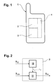
- FIG. 1 shows a mobile communication device 1.
- the mobile communication device 1 is in the present embodiment a mobile phone for a European Telecommunications Standard Institute system or Universal Mobile Telecommunications system, an Association of radio Industries and Businesses Wideband Code Division Multiple Access communications system, and/or a Wideband Code Division Multiple Access system being defined by 3 rd Generation Partnership Project communications system.
- the mobile communication device 1 may be a multi-mode mobile station, capable of operating, for example in a Global System for Mobile Telecommunications (GSM) system as well as a UMTS system.
- GSM Global System for Mobile Telecommunications
- UMTS Universal Mobile Telecommunications
- the mobile communication device 1 comprises the receiver arrangement 2 and processing means 3.
- the receiver arrangement 2 receives signals from a base station (not shown).
- the processing means 3 among many other tasks, proces signals received from the receiver arrangement 2.
- the mobile communication device 1 may further comprise additional circuitry, filter means, processing means, storage means, man machine interfaces and so on which are denoted by reference number 4.
- FIG. 2 shows the receiver arrangement 2 in more detail.
- the receiver arrangement 2 comprises a multi-path identification arrangement 10 which determines time delays ⁇ 1 , Vietnamese, ⁇ n based upon an identification signal S ID received from the base station. Due to reflections and different travels of the signal sent by the base station the identification signal S ID comprises time delayed versions of the signal originally sent from the base station.
- the receiver arrangement 2 further comprises a descrambling arrangement descrambling an information signal S info originating from the base station based upon the time delays ⁇ 1 , ...., ⁇ n provided by the multi-path identification arrangement.
- the output of the descrambling arrangement 11 is a signal S de which is further processed by the processor means 3.
- the information signal S info carries user information such as speech, email or internet information.
- FIG. 3 discloses the multi-path identification arrangement 10 in more detail.
- the multi-path identification arrangement comprises a signal generator 22 for generating locally generated signals S L1 , Vietnamese, S Lm having essentially the same information content as the identification signal S ID of the base station.
- the locally generated signals S L1 , ...., S Lm are timed delayed from each other by a delay between 100ns and 300ns. In the current embodiment the delay is 130ns. m is preferably less than 100. Preferably it is about 80. In the current embodiment m is 77.
- the largest absolute delay time of a locally generated signal S L1 , ...., S Lm is preferably between 10 ⁇ s and 20 ⁇ s.
- the multi-path identification arrangement further comprises a correlator 20 for correlating the identification signal S ID with the locally generated signals S L1 , ...., S Lm.
- the correlation can be carried out serial or in parallel or in a combination of both methods. All three possibilities are within the scopes of the claims. If the correlation is carried out in parallel correlator 20 comprises m subcorrelators 201, 202 and 203 as indicated in FIG. 4.
- the outputs of the correlator 20 are correlated signals S C1 ,.... S Cm . They are inputs to a first filter 21 removing noise from the signals.
- the output signals of the filter are denoted with S CF1 , ...., S CFm. These signals are fed into a ranking arrangement 23 which is shown in more detail in FIG.
- the ranking arrangement 23 identifies the j signals S R1 , ...., S Rj of highest power out of the m correlated signals S CF1 , ...., S CFm .
- the signals of highest power S R1 , .... , S Rj are outputs of the ranking arrangement 23 and inputs to a second filter 24.
- the second filter 24 is preferably a more complex filter than the first filter 21.
- the output signals S RF1 , ... , S RFj of the second filter 24 are fed into an evaluation arrangement 25.
- the evaluation arrangement 25 determines the delay times ⁇ 1 ...., ⁇ n .
- the hypothesis test is preferably a likelihood ratio test which is for example disclosed in K. Sam Shanmugan and A.M. Breipohl "Random signals, the detection estimation and data analysis" John Wiley and Sons, 1988.
- the evaluation arrangement 25 also generates control parameters c ⁇ 1 , ...., c ⁇ n for controlling the signal generator 22.
- FIG. 5 discloses the ranking arrangement 23 in more detail.
- the ranking arrangement 23 comprises a power detector 26 detecting the power P 1 , ...., P m of the signals S CF1 , across , S CFm .
- the values for P 1 , .... , P m as well as the signals S CF1 , Vietnamese , S CFm are fed into a ranking filter 27.
- the ranking filter 27 determines j signals S R1 , Vietnamese, S CFm .
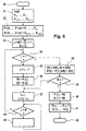
- a preferred embodiment of the ranking filter 27 is shown in FIG. 6 in terms of a flow chart.
- a step 31 is carried out reading the values of P 1 , Vietnamese, P m and the signals S CF1 , .... , S CFm .
- Step 38 is followed by decision block 39 checking whether R is equal to 1. If this condition is not fulfilled decision block 39 is followed by a step 37.
- Step 37 is followed by decision block 43 checking whether J is greater than R. If this decision is not fulfilled decision block 43 is followed by decision block 34. If however this decision is fulfilled, decision block 43 is followed by a step 44. Step 44 is shown in more detail in FIG. 7. Step 44 is followed by decision block 43.
- Step 51 is followed by a decision block 52.
- decision block 50 is followed by decision block 52 checking whether PO > P(J)
- Step 55 is followed by decision block 43.
- Step 53 is followed by a decision block 43.
- FIG. 8 shows the descrambling arrangement 11 in more detail.
- the descrambling arrangement 8 comprises a delay arrangement 50 delaying the information signal S info by the delay times ⁇ 1 , ...., ⁇ n to obtain delayed information signals S info1 , ...., S infon of the information signal S info respectively.
- the delayed information signals S info1 , Vietnamese, S infon are added by a summation arrangement 51.
- the output of the summation point 31 is signal S de which is the sum of S info1 , ...., S infon .
- the method or communication device may be used in an European Telecommunications Standard Institute (ETSI) or Universal Mobile Telecommunications System (UMTS), an Association of Radio Industries and Businesses (ARIB) Wideband Code Division Multiple Access (WCDMA) system, or a Wideband Code Division Multiple Access (WCDMA) system being defined by 3 rd Generation Partnership Project (3GPP) system.
- ETSI European Telecommunications Standard Institute
- UMTS Universal Mobile Telecommunications System
- ARIB Association of Radio Industries and Businesses
- WCDMA Wideband Code Division Multiple Access
- WCDMA Wideband Code Division Multiple Access
- 3GPP 3 rd Generation Partnership Project
- the present invention may be applied to various frequency bands.
- the present invention may be applied for monitoring in other types of mobile communication systems than those described herein.
Abstract
Description
- The present invention relates to a receiver, in particular a Code Division Multiple Access (CDMA) receiver, for a, in particular mobile, communication device.
- A (mobile) communication device in particular a mobile communication device having a Code Division Multiple Access (CDMA) receiver, may be allocated to a base station. When the mobile communication device is allocated to the base station, the mobile communication device will, due to reflections, receive multi-path components of a signal sent by the base station. A known receiver for receiving multi-path signals from a base station comprises a correlator for correlating the identification signal of the base station with locally generated signals and an hypothesis algorithm judging whether the time delay of the locally generated signal matches the delay time of a multi-path component in the received identification signal. A receiver of higher performance may be found in Viterbi, Andrew, "Principles of Spread Spectrum Communications", Addison-Wesley Publishing Company 1995, disclosing a multiple dual series search acquisition scheme. Such a multiple dual series search acquisition scheme comprises both a correlator for correlating an identification signal received from the base station and an additional hypothesis testing.
- A known receiver architecture for CDMA mobile systems is the rake receiver. See Price, R. et al., "A Communication Technique for Multipath Channels," Proceedings of the IRE, 1958, vol. 46, pp. 555-570. A rake receiver consists of a bank of correlation-type receivers or correlators. Each correlator of the bank of correlators is used to detect a separate multi-path component.
- A further acquisition scheme is disclosed in Gweon-Do Jo, Sook-Heyn Chang, Hye-Yeon Kweon, and Sun-Young Kim. Performance Evaluation of Pilot Channel Acquisition System in CDMA Forward Link, IEEE 48th Vehicular Technology Conference, 1998, Vol. 2, pp. 1244-1248, however it turned out that this acquisition scheme fails if multi-path components of a signal are present.
- It is an object of the present invention to improve a receiver, in particular a CDMA receiver, for a, in particular mobile, communication device.
- The object is achieved by the receiver arrangement according to
claim 1 or a communication device according toclaim 10. Such a receiver arrangement or mobile communication device comprises - a signal generator for generating at least m locally generated signals, which are time delayed by a delay time from each other,
- a correlator for obtaining m correlated signals by correlating a received identification signal with the m locally generated signals, and
- a ranking arrangement for identifying j correlated signals of highest power out of the m correlated signals.
- The object of the present invention is further achieved by a method for operating a receiver arrangement by receiving an identification signal and obtaining m correlated signals by correlating the identification signal with m locally generated signals, which are time delayed from each other, and identifying j correlated signals of highest power out of the m correlated signals.
- The object of the present invention is further achieved by a method for operating a receiver arrangement, by
- receiving an information signal and an identification signal,
- obtaining m correlated signals by correlating the identification signal with m locally generated signals, which are time delayed from each other,
- identifying j correlated signals of highest power out of the m locally generated signals,
- selecting n correlated signals out of the j correlated signals, wherein n is less than or equal j,
- obtaining n or less delayed information signals by delaying the information signal by time delays which correspond to the n selected correlated signals, and
- adding the n or less delayed information signals or adding the n or less delayed information signals and the information signal.
- In a preferred embodiment of the invention the receiver arrangement is a Code Division Multiple Access, CDMA, receiver, in particular a rake receiver.
- In a further preferred embodiment of the invention the delay time is less than 20µs.
- In a further preferred embodiment of the invention m is less than 100, in particular about 80.
- In a further preferred embodiment of the invention j is grater than 5 and less than m/2, in particular less than 30.
- In a further preferred embodiment of the invention j is less than 20.
- In a further preferred embodiment of the invention the receiver arrangement comprises an evaluation arrangement for selecting n correlated signals out of the j correlated signals of highest power, wherein n is less than or equal j.
- In a further preferred embodiment of the invention the receiver arrangement, which is capable of receiving an information signal, comprises a delay arrangement for obtaining n or less delayed information signals by delaying the information signal by delay times which correspond to the n selected correlated signals.
- In a further preferred embodiment of the invention the receiver arrangement comprises a summation arrangement for adding the n or less delayed information signals or adding the n or less delayed information signals and the information signal.
- The communication device is preferably a mobile communication device, in particular a mobile phone or mobile computer. However the communication device may also be part of a wireless building communications system.
- Further advantages of the present invention will become apparent from the claims and the description below, based on the drawings, in which:
- FIG. 1
- shows a mobile communication device,
- FIG. 2
- shows a receiver arrangement,
- FIG. 3
- discloses the multi-path identification arrangement,
- FIG. 4
- shows a correlator,
- FIG. 5
- discloses the ranking arrangement,
- FIG. 6
- shows an embodiment of a ranking filter in terms of a flow chart,
- FIG. 7
- shows a part of the flow chart of FIG. 6, and
- FIG. 8
- shows a descrambling arrangement
- FIG. 1 shows a
mobile communication device 1. Themobile communication device 1 is in the present embodiment a mobile phone for a European Telecommunications Standard Institute system or Universal Mobile Telecommunications system, an Association of radio Industries and Businesses Wideband Code Division Multiple Access communications system, and/or a Wideband Code Division Multiple Access system being defined by 3rd Generation Partnership Project communications system. - The
mobile communication device 1 may be a multi-mode mobile station, capable of operating, for example in a Global System for Mobile Telecommunications (GSM) system as well as a UMTS system. - The
mobile communication device 1 comprises thereceiver arrangement 2 and processing means 3. Thereceiver arrangement 2 receives signals from a base station (not shown). The processing means 3, among many other tasks, proces signals received from thereceiver arrangement 2. Themobile communication device 1 may further comprise additional circuitry, filter means, processing means, storage means, man machine interfaces and so on which are denoted by reference number 4. - FIG. 2 shows the
receiver arrangement 2 in more detail. Thereceiver arrangement 2 comprises amulti-path identification arrangement 10 which determines time delays τ1, ....., τn based upon an identification signal SID received from the base station. Due to reflections and different travels of the signal sent by the base station the identification signal SID comprises time delayed versions of the signal originally sent from the base station. - The
receiver arrangement 2 further comprises a descrambling arrangement descrambling an information signal Sinfo originating from the base station based upon the time delays τ1, ...., τn provided by the multi-path identification arrangement. The output of the descramblingarrangement 11 is a signal Sde which is further processed by the processor means 3. The information signal Sinfo carries user information such as speech, email or internet information. - FIG. 3 discloses the
multi-path identification arrangement 10 in more detail. The multi-path identification arrangement comprises a signal generator 22 for generating locally generated signals SL1, ....., SLm having essentially the same information content as the identification signal SID of the base station. The locally generated signals SL1, ...., SLm are timed delayed from each other by a delay between 100ns and 300ns. In the current embodiment the delay is 130ns. m is preferably less than 100. Preferably it is about 80. In the current embodiment m is 77. The largest absolute delay time of a locally generated signal SL1, ...., SLm is preferably between 10 µs and 20 µs. - The multi-path identification arrangement further comprises a
correlator 20 for correlating the identification signal SID with the locally generated signals SL1, ...., SLm. The correlation can be carried out serial or in parallel or in a combination of both methods. All three possibilities are within the scopes of the claims. If the correlation is carried out inparallel correlator 20 comprises msubcorrelators correlator 20 are correlated signals SC1,.... SCm. They are inputs to afirst filter 21 removing noise from the signals. The output signals of the filter are denoted with SCF1, ...., SCFm. These signals are fed into aranking arrangement 23 which is shown in more detail in FIG. 5. Theranking arrangement 23 identifies the j signals SR1, ...., SRj of highest power out of the m correlated signals SCF1, ...., SCFm. The signals of highest power SR1, .... , SRj are outputs of theranking arrangement 23 and inputs to asecond filter 24. Thesecond filter 24 is preferably a more complex filter than thefirst filter 21. The output signals SRF1, ... , SRFj of thesecond filter 24 are fed into anevaluation arrangement 25. Theevaluation arrangement 25 determines the delay times τ1...., τn. This is most preferably done via a hypothesis testing algorithm which tests the hypothesis that a delay time τi matches a delay time of a signal component in the identification signal SID. The hypothesis test is preferably a likelihood ratio test which is for example disclosed in K. Sam Shanmugan and A.M. Breipohl "Random signals, the detection estimation and data analysis" John Wiley and Sons, 1988. - The
evaluation arrangement 25 also generates control parameters cτ1, ...., cτn for controlling the signal generator 22. - FIG. 5 discloses the
ranking arrangement 23 in more detail. Theranking arrangement 23 comprises apower detector 26 detecting the power P1, ...., Pm of the signals SCF1, ..... , SCFm. The values for P1, .... , Pm as well as the signals SCF1, ..... , SCFm are fed into aranking filter 27. The rankingfilter 27 determines j signals SR1, ....., SRj of highest power out of the signals SCF1, ...., SCFm. - A preferred embodiment of the
ranking filter 27 is shown in FIG. 6 in terms of a flow chart. After the start the 30 astep 31 is carried out reading the values of P1,....., Pm and the signals SCF1, .... , SCFm. Step 31 is followed by astep 32, assigning
P(1), ..., P(m) = P1, ...., Pm
and
S(1), ..., S(m) = SCF1, ....., SCFm
i.e., a variable P(1) is assigned to have a value P1, a variable P(2) is assigned to have a value P2, etc. and a signal S(1) to be SCF1, a signal S(2) to be SCF2, etc. -
Step 32 is followed by astep 33 defining variables L and R as -
Step 33 is followed by adecision block 34 checking whether L is greater that 1. If this condition is fulfilleddecision block 34 is followed by astep 35 decreasing L by 1, i.e.: -
Step 35 is followed astep 36 assigning the following: -
Step 36 is followed bystep 37 with - If L is not greater than 1
decision block 34 is followed by astep 38 assigning: -
Step 38 is followed bydecision block 39 checking whether R is equal to 1. If this condition is not fulfilleddecision block 39 is followed by astep 37. -
Step 37 is followed bydecision block 43 checking whether J is greater than R. If this decision is not fulfilleddecision block 43 is followed bydecision block 34. If however this decision is fulfilled,decision block 43 is followed by astep 44.Step 44 is shown in more detail in FIG. 7.Step 44 is followed bydecision block 43. - If R equals 1
decision block 39 is followed by astep 40 assigning: -
Step 40 followed by astep 41 assigning - After 41 is carried out the program is terminated as indicated with
reference number 42. - FIG. 7 shows step 44 in more detail.
Decision block 43 is followed by a decision block checking whetherdecision block 50 is followed by astep 51 incrementing J: -
Step 51 is followed by adecision block 52. - If, however, the condition
decision block 50 is followed bydecision block 52 checking whether - If this condition is met,
decision block 52 is followed by astep 54 with -
Step 54 is followed by astep 55 with: -
Step 55 is followed bydecision block 43. - If the condition
decision block 52 is followed by astep 53 with: -
Step 53 is followed by adecision block 43. - FIG. 8 shows the
descrambling arrangement 11 in more detail. The descrambling arrangement 8 comprises adelay arrangement 50 delaying the information signal Sinfo by the delay times τ1, ...., τn to obtain delayed information signals Sinfo1, ...., Sinfon of the information signal Sinfo respectively. The delayed information signals Sinfo1, ....., Sinfon are added by asummation arrangement 51. The output of thesummation point 31 is signal Sde which is the sum of Sinfo1, ...., Sinfon. - In all the embodiments of the present invention described herein, as well as other embodiments of the present invention, the method or communication device may be used in an European Telecommunications Standard Institute (ETSI) or Universal Mobile Telecommunications System (UMTS), an Association of Radio Industries and Businesses (ARIB) Wideband Code Division Multiple Access (WCDMA) system, or a Wideband Code Division Multiple Access (WCDMA) system being defined by 3rd Generation Partnership Project (3GPP) system.
- Various embodiments within the scope of the present invention are possible. For example, the present invention may be applied to various frequency bands. Additionally, the present invention may be applied for monitoring in other types of mobile communication systems than those described herein.
Claims (14)
- Receiver arrangement (2), in particular for a mobile communication device (1), comprising a signal generator (22) for generating at least m locally generated signals (SL1, ....., SLm), which are time delayed by a delay time from each other, and a correlator for obtaining m correlated signals (SC1, ...., SCm) by correlating a received identification signal with the m locally generated signals (SL1, ....., SLm),
characterized in that,
the receiver arrangement (2) comprises a ranking arrangement (23) for identifying j correlated signals (SR1, ...., SRj) of highest power out of the m correlated signals (SC1, ...., SCm). - Receiver arrangement (2) according to claim 1,
characterized in that,
the receiver arrangement (2) is a Code Division Multiple Access, CDMA, receiver, in particular a rake receiver. - Receiver arrangement (2) according to claim 1 or 2,
characterized in that,
the delay time is less than 20µs. - Receiver arrangement (2) according to claim 1, 2, or 3,
characterized in that,
m is less than 100, in particular about 80. - Receiver arrangement (2) according to claim 1, 2, 3, or 4,
characterized in that,
j is grater than 5 and less than m/2, in particular less than 30. - Receiver arrangement (2) according to claim 1, 2, 3, 4, or 5,
characterized in that,
j is less than 20. - Receiver arrangement (2) according to one of the foregoing claims,
characterized in that,
the receiver arrangement (2) comprises an evaluation arrangement (25) for selecting n correlated signals of the j correlated signals (SR1, ...., SRj) of highest power, wherein n is less than or equal j. - Receiver arrangement (2) according to claim 7, wherein the receiver arrangement (2) is capable of receiving an information signal,
characterized in that,
the receiver arrangement (2) comprises a delay arrangement for obtaining n or less delayed information signals by delaying the information signal by delay times which correspond to the n selected correlated signals. - Receiver arrangement (2) according to claim 8,
characterized in that,
the receiver arrangement (2) comprises a summation arrangement for adding the n or less delayed information signals or adding the n or less delayed information signals and the information signal. - Communication device, in particular comprising a receiver arrangement (2) according to one of the foregoing claims, having a signal generator (22) for generating at least m locally generated signals (SL1, ....., SLm), which are time delayed by a delay time from each other, and a correlator for obtaining m correlated signals (SC1, ...., SCm) by correlating a received identification signal with the m locally generated signals (SL1, ....., SLm),
characterized in that,
the receiver comprises a ranking arrangement (23) for
identifying j correlated signals (SR1, ...., SRj) of highest power out of the m correlated signals (SC1, ...., SCm). - Communication device according to claim 10,
characterized in that,
the communication device is a mobile communication device
(1). - Communication device according to claim 11,
characterized in that,
the communication device is a mobile phone or mobile computer. - Method for operating a receiver arrangement (2), in particular for operating a receiver arrangement (2) according to one of the claims 1 through 9, by receiving an identification signal and obtaining m correlated signals (SC1, ...., SCm) by correlating the identification signal with m locally generated signals (SL1, ....., SLm), which are time delayed from each other,
characterized in that,
j correlated signals (SR1, ...., SRj) of highest power out of the m correlated signals (SC1, ...., SCm) are identified. - Method for operating a receiver arrangement (2), in particular for operating a receiver arrangement (2) according to one of the claims 1 through 9, byreceiving an information signal and an identification signal,obtaining m correlated signals (SC1, ...., SCm) by correlating the identification signal with m locally generated signals (SL1, ....., SLm), which are time delayed from each other,identifying j correlated signals (SR1, ...., SRj) of highest power out of the m locally generated signals (SL1, ....., SLm),selecting n correlated signals out of the j correlated signals, wherein n is less than or equal j,obtaining n or less delayed information signals by delaying the information signal by time delays which correspond to the n selected correlated signals, andadding the n or less delayed information signals or adding the n or less delayed information signals and the information signal.
Priority Applications (3)
| Application Number | Priority Date | Filing Date | Title |
|---|---|---|---|
| EP20000110027 EP1154585B1 (en) | 2000-05-12 | 2000-05-12 | Receiver for a communication device for a multi-path radio channel |
| DE2000638163 DE60038163T2 (en) | 2000-05-12 | 2000-05-12 | Receiver for a communication device for a multipath radio channel |
| DK00110027T DK1154585T3 (en) | 2000-05-12 | 2000-05-12 | Receiver for a multi-channel radio channel communication device |
Applications Claiming Priority (1)
| Application Number | Priority Date | Filing Date | Title |
|---|---|---|---|
| EP20000110027 EP1154585B1 (en) | 2000-05-12 | 2000-05-12 | Receiver for a communication device for a multi-path radio channel |
Publications (2)
| Publication Number | Publication Date |
|---|---|
| EP1154585A1 true EP1154585A1 (en) | 2001-11-14 |
| EP1154585B1 EP1154585B1 (en) | 2008-02-27 |
Family
ID=8168683
Family Applications (1)
| Application Number | Title | Priority Date | Filing Date |
|---|---|---|---|
| EP20000110027 Revoked EP1154585B1 (en) | 2000-05-12 | 2000-05-12 | Receiver for a communication device for a multi-path radio channel |
Country Status (3)
| Country | Link |
|---|---|
| EP (1) | EP1154585B1 (en) |
| DE (1) | DE60038163T2 (en) |
| DK (1) | DK1154585T3 (en) |
Cited By (3)
| Publication number | Priority date | Publication date | Assignee | Title |
|---|---|---|---|---|
| GB2375024A (en) * | 2001-01-15 | 2002-10-30 | Nec Corp | CDMA receiver divides a delay profile into regions and meaures the power in each region, with regions of higher power being measured more frequently |
| EP1672808A1 (en) * | 2004-12-20 | 2006-06-21 | Telefonaktiebolaget L M Ericsson (Publ) | Selecting peak delay values for a RAKE receiver |
| WO2006066765A1 (en) * | 2004-12-20 | 2006-06-29 | Telefonaktiebolaget Lm Ericsson (Publ) | Selecting peak delay values for a rake receiver |
Citations (2)
| Publication number | Priority date | Publication date | Assignee | Title |
|---|---|---|---|---|
| US5280472A (en) * | 1990-12-07 | 1994-01-18 | Qualcomm Incorporated | CDMA microcellular telephone system and distributed antenna system therefor |
| WO1996010873A1 (en) * | 1994-09-30 | 1996-04-11 | Qualcomm Incorporated | Multipath search processor for a spread spectrum multiple access communication system |
-
2000
- 2000-05-12 EP EP20000110027 patent/EP1154585B1/en not_active Revoked
- 2000-05-12 DK DK00110027T patent/DK1154585T3/en active
- 2000-05-12 DE DE2000638163 patent/DE60038163T2/en not_active Expired - Lifetime
Patent Citations (2)
| Publication number | Priority date | Publication date | Assignee | Title |
|---|---|---|---|---|
| US5280472A (en) * | 1990-12-07 | 1994-01-18 | Qualcomm Incorporated | CDMA microcellular telephone system and distributed antenna system therefor |
| WO1996010873A1 (en) * | 1994-09-30 | 1996-04-11 | Qualcomm Incorporated | Multipath search processor for a spread spectrum multiple access communication system |
Cited By (5)
| Publication number | Priority date | Publication date | Assignee | Title |
|---|---|---|---|---|
| GB2375024A (en) * | 2001-01-15 | 2002-10-30 | Nec Corp | CDMA receiver divides a delay profile into regions and meaures the power in each region, with regions of higher power being measured more frequently |
| GB2375024B (en) * | 2001-01-15 | 2003-04-16 | Nec Corp | CDMA receiver,method of operation and program therefor |
| US7254162B2 (en) | 2001-01-15 | 2007-08-07 | Nec Corporation | CDMA receiver performing a path search, path search method, and program therefor |
| EP1672808A1 (en) * | 2004-12-20 | 2006-06-21 | Telefonaktiebolaget L M Ericsson (Publ) | Selecting peak delay values for a RAKE receiver |
| WO2006066765A1 (en) * | 2004-12-20 | 2006-06-29 | Telefonaktiebolaget Lm Ericsson (Publ) | Selecting peak delay values for a rake receiver |
Also Published As
| Publication number | Publication date |
|---|---|
| DE60038163D1 (en) | 2008-04-10 |
| DE60038163T2 (en) | 2009-03-26 |
| EP1154585B1 (en) | 2008-02-27 |
| DK1154585T3 (en) | 2008-06-23 |
Similar Documents
| Publication | Publication Date | Title |
|---|---|---|
| US6222834B1 (en) | Spread spectrum communication receiver | |
| EP1121068B1 (en) | An apparatus and method for performing a signal search in a coherent wireless communication system | |
| EP0654913A2 (en) | Synchronization technique for pseudonoise signals | |
| US7050484B2 (en) | Method of detecting path timings and CDMA receiving apparatus using the same | |
| US6895036B2 (en) | Apparatus and method for sub-chip offset correlation in spread-spectrum communication systems | |
| US7609785B2 (en) | Mitigation of interference in cell search by wireless transmit and receive units | |
| US20020064146A1 (en) | CDMA mobile communications apparatus and base station detecting method used therefor | |
| US7039097B2 (en) | CDMA receiver, path search method and program | |
| KR101032333B1 (en) | Multi-path searching | |
| KR100197352B1 (en) | Parallel acquisition system with reference filter | |
| US7194018B2 (en) | Apparatus for searching multipath in spread spectrum communications system and method thereof | |
| KR100381877B1 (en) | Cdma baseband receiver capable of establishing synchronization with peripheral base stations | |
| FI104020B (en) | Reception procedure and recipients | |
| EP1154585B1 (en) | Receiver for a communication device for a multi-path radio channel | |
| US7359399B2 (en) | CDMA path protection method based on path protection information | |
| EP1148657A2 (en) | Demodulation apparatus and demodulation method for mobile communication | |
| KR101015411B1 (en) | Synchronization strategy and architecture for spread-spectrum receivers | |
| JP2004229305A (en) | Method and device of cell search in wcdma system | |
| US20040184411A1 (en) | Path searching circuit, path searching method, and path searching program in a CDMA communication system | |
| EP1391999A1 (en) | Synchronization and cell search method and apparatus for a WCDMA system | |
| CN1260902C (en) | CDMA system multi-path search peak value identifying device and method | |
| CN111446983B (en) | Multipath searcher, cell search device and cell search method | |
| KR100287914B1 (en) | High effective Apparatus and Method for sorting Signal searching result | |
| KR100399008B1 (en) | Apparatus for acquisition for wideband DS/CDMA signal | |
| EP1146657A1 (en) | Mobile station and method for allocating rake fingers |
Legal Events
| Date | Code | Title | Description |
|---|---|---|---|
| PUAI | Public reference made under article 153(3) epc to a published international application that has entered the european phase |
Free format text: ORIGINAL CODE: 0009012 |
|
| AK | Designated contracting states |
Kind code of ref document: A1 Designated state(s): AT BE CH CY DE DK ES FI FR GB GR IE IT LI LU MC NL PT SE Kind code of ref document: A1 Designated state(s): DE DK FR GB IT SE |
|
| AX | Request for extension of the european patent |
Free format text: AL;LT;LV;MK;RO;SI |
|
| 17P | Request for examination filed |
Effective date: 20020514 |
|
| AKX | Designation fees paid |
Free format text: DE DK FR GB IT SE |
|
| 17Q | First examination report despatched |
Effective date: 20070206 |
|
| RAP1 | Party data changed (applicant data changed or rights of an application transferred) |
Owner name: IPCOM GMBH & CO. KG |
|
| GRAP | Despatch of communication of intention to grant a patent |
Free format text: ORIGINAL CODE: EPIDOSNIGR1 |
|
| GRAS | Grant fee paid |
Free format text: ORIGINAL CODE: EPIDOSNIGR3 |
|
| GRAA | (expected) grant |
Free format text: ORIGINAL CODE: 0009210 |
|
| AK | Designated contracting states |
Kind code of ref document: B1 Designated state(s): DE DK FR GB IT SE |
|
| REG | Reference to a national code |
Ref country code: GB Ref legal event code: FG4D |
|
| REF | Corresponds to: |
Ref document number: 60038163 Country of ref document: DE Date of ref document: 20080410 Kind code of ref document: P |
|
| REG | Reference to a national code |
Ref country code: SE Ref legal event code: TRGR |
|
| REG | Reference to a national code |
Ref country code: DK Ref legal event code: T3 |
|
| ET | Fr: translation filed | ||
| PLBI | Opposition filed |
Free format text: ORIGINAL CODE: 0009260 |
|
| PLAX | Notice of opposition and request to file observation + time limit sent |
Free format text: ORIGINAL CODE: EPIDOSNOBS2 |
|
| 26 | Opposition filed |
Opponent name: NOKIA CORPORATOIN Effective date: 20081127 |
|
| PLAF | Information modified related to communication of a notice of opposition and request to file observations + time limit |
Free format text: ORIGINAL CODE: EPIDOSCOBS2 |
|
| PLAB | Opposition data, opponent's data or that of the opponent's representative modified |
Free format text: ORIGINAL CODE: 0009299OPPO |
|
| PLBB | Reply of patent proprietor to notice(s) of opposition received |
Free format text: ORIGINAL CODE: EPIDOSNOBS3 |
|
| PLAF | Information modified related to communication of a notice of opposition and request to file observations + time limit |
Free format text: ORIGINAL CODE: EPIDOSCOBS2 |
|
| RDAF | Communication despatched that patent is revoked |
Free format text: ORIGINAL CODE: EPIDOSNREV1 |
|
| APBM | Appeal reference recorded |
Free format text: ORIGINAL CODE: EPIDOSNREFNO |
|
| APBP | Date of receipt of notice of appeal recorded |
Free format text: ORIGINAL CODE: EPIDOSNNOA2O |
|
| APAH | Appeal reference modified |
Free format text: ORIGINAL CODE: EPIDOSCREFNO |
|
| APBQ | Date of receipt of statement of grounds of appeal recorded |
Free format text: ORIGINAL CODE: EPIDOSNNOA3O |
|
| PLAB | Opposition data, opponent's data or that of the opponent's representative modified |
Free format text: ORIGINAL CODE: 0009299OPPO |
|
| R26 | Opposition filed (corrected) |
Opponent name: NOKIA CORPORATION Effective date: 20081127 |
|
| APBY | Invitation to file observations in appeal sent |
Free format text: ORIGINAL CODE: EPIDOSNOBA2O |
|
| APCA | Receipt of observations in appeal recorded |
Free format text: ORIGINAL CODE: EPIDOSNOBA4O |
|
| PLAB | Opposition data, opponent's data or that of the opponent's representative modified |
Free format text: ORIGINAL CODE: 0009299OPPO |
|
| R26 | Opposition filed (corrected) |
Opponent name: MICROSOFT MOBILE OY Effective date: 20081127 |
|
| REG | Reference to a national code |
Ref country code: FR Ref legal event code: PLFP Year of fee payment: 17 |
|
| PGFP | Annual fee paid to national office [announced via postgrant information from national office to epo] |
Ref country code: GB Payment date: 20160523 Year of fee payment: 17 Ref country code: DE Payment date: 20160531 Year of fee payment: 17 |
|
| PGFP | Annual fee paid to national office [announced via postgrant information from national office to epo] |
Ref country code: IT Payment date: 20160524 Year of fee payment: 17 Ref country code: DK Payment date: 20160523 Year of fee payment: 17 Ref country code: SE Payment date: 20160523 Year of fee payment: 17 Ref country code: FR Payment date: 20160523 Year of fee payment: 17 |
|
| REG | Reference to a national code |
Ref country code: DE Ref legal event code: R064 Ref document number: 60038163 Country of ref document: DE Ref country code: DE Ref legal event code: R103 Ref document number: 60038163 Country of ref document: DE |
|
| APBU | Appeal procedure closed |
Free format text: ORIGINAL CODE: EPIDOSNNOA9O |
|
| RDAG | Patent revoked |
Free format text: ORIGINAL CODE: 0009271 |
|
| STAA | Information on the status of an ep patent application or granted ep patent |
Free format text: STATUS: PATENT REVOKED |
|
| 27W | Patent revoked |
Effective date: 20170117 |
|
| GBPR | Gb: patent revoked under art. 102 of the ep convention designating the uk as contracting state |
Effective date: 20170117 |
|
| REG | Reference to a national code |
Ref country code: SE Ref legal event code: ECNC |