EP1217602A2 - Updating image frames in a display device comprising a frame buffer - Google Patents
Updating image frames in a display device comprising a frame buffer Download PDFInfo
- Publication number
- EP1217602A2 EP1217602A2 EP01000582A EP01000582A EP1217602A2 EP 1217602 A2 EP1217602 A2 EP 1217602A2 EP 01000582 A EP01000582 A EP 01000582A EP 01000582 A EP01000582 A EP 01000582A EP 1217602 A2 EP1217602 A2 EP 1217602A2
- Authority
- EP
- European Patent Office
- Prior art keywords
- synchronization signal
- frame
- image frames
- screen
- control system
- Prior art date
- Legal status (The legal status is an assumption and is not a legal conclusion. Google has not performed a legal analysis and makes no representation as to the accuracy of the status listed.)
- Granted
Links
Images
Classifications
-
- G—PHYSICS
- G09—EDUCATION; CRYPTOGRAPHY; DISPLAY; ADVERTISING; SEALS
- G09G—ARRANGEMENTS OR CIRCUITS FOR CONTROL OF INDICATING DEVICES USING STATIC MEANS TO PRESENT VARIABLE INFORMATION
- G09G5/00—Control arrangements or circuits for visual indicators common to cathode-ray tube indicators and other visual indicators
- G09G5/001—Arbitration of resources in a display system, e.g. control of access to frame buffer by video controller and/or main processor
-
- G—PHYSICS
- G06—COMPUTING; CALCULATING OR COUNTING
- G06F—ELECTRIC DIGITAL DATA PROCESSING
- G06F3/00—Input arrangements for transferring data to be processed into a form capable of being handled by the computer; Output arrangements for transferring data from processing unit to output unit, e.g. interface arrangements
- G06F3/14—Digital output to display device ; Cooperation and interconnection of the display device with other functional units
- G06F3/147—Digital output to display device ; Cooperation and interconnection of the display device with other functional units using display panels
-
- G—PHYSICS
- G09—EDUCATION; CRYPTOGRAPHY; DISPLAY; ADVERTISING; SEALS
- G09G—ARRANGEMENTS OR CIRCUITS FOR CONTROL OF INDICATING DEVICES USING STATIC MEANS TO PRESENT VARIABLE INFORMATION
- G09G5/00—Control arrangements or circuits for visual indicators common to cathode-ray tube indicators and other visual indicators
- G09G5/003—Details of a display terminal, the details relating to the control arrangement of the display terminal and to the interfaces thereto
- G09G5/005—Adapting incoming signals to the display format of the display terminal
-
- G—PHYSICS
- G09—EDUCATION; CRYPTOGRAPHY; DISPLAY; ADVERTISING; SEALS
- G09G—ARRANGEMENTS OR CIRCUITS FOR CONTROL OF INDICATING DEVICES USING STATIC MEANS TO PRESENT VARIABLE INFORMATION
- G09G5/00—Control arrangements or circuits for visual indicators common to cathode-ray tube indicators and other visual indicators
- G09G5/36—Control arrangements or circuits for visual indicators common to cathode-ray tube indicators and other visual indicators characterised by the display of a graphic pattern, e.g. using an all-points-addressable [APA] memory
- G09G5/39—Control of the bit-mapped memory
- G09G5/393—Arrangements for updating the contents of the bit-mapped memory
-
- G—PHYSICS
- G09—EDUCATION; CRYPTOGRAPHY; DISPLAY; ADVERTISING; SEALS
- G09G—ARRANGEMENTS OR CIRCUITS FOR CONTROL OF INDICATING DEVICES USING STATIC MEANS TO PRESENT VARIABLE INFORMATION
- G09G2360/00—Aspects of the architecture of display systems
- G09G2360/18—Use of a frame buffer in a display terminal, inclusive of the display panel
Definitions
- the invention relates to updating image frames on a screen, particularly on screens comprising memory.
- Display units are used for example in different computer systems and portable terminals, such as mobile stations, for displaying text and images to the user of the device.
- a display signal typically comprising a display data signal and a synchronization signal, is input to the display unit.
- the display data signal comprises image frames that are distinguished from each other by means of a frame synchronization signal comprised by the synchronization signal.
- the synchronization signal also comprises a line synchronization signal for determining the separation of the lines comprised by one image frame.
- Image frames are displayed to the user of a device by means of a display screen that receives image frames at an encoding rate that thus determines the number of image frames received in a time unit. Image frames are updated on the screen at a frequency called screen refresh rate.
- the manufacturer typically defines a target refresh rate that is determined according to the properties of the screen and the interfaces associated therewith. Since the costs of a display unit typically have to be kept within given limits, the above properties also set a maximum value for the target refresh rate. This may lead to a situation where the refresh rate to be used is lower than the encoding rate at which the display unit receives image frames. In this case the display unit has to convert the frame frequency by adapting the image frames received at the encoding rate to be displayed on the screen at the refresh rate.
- Modern display units particularly suitable for displaying moving image, such as video or various games, typically comprise memory for buffering image frames before the image frames are displayed on the screen.
- One image frame can typically be stored in the available buffer memory, allowing the frame frequency to be converted by reading the data comprised by the stored image frame and updating it to the screen at the refresh rate used.
- the problem in the above arrangement is the limited size of the buffer memory available in display units, which easily causes what is known as tearing to the image displayed on the screen, i.e. one part of the image displayed on the screen is composed of one image frame and another part of another image frame. On the screen this is visible as flashing lines or breaking in a laterally moving object. Tearing results from a new image frame being stored in the buffer memory before the previous image frame is entirely updated on the screen.
- the display unit could use a larger buffer memory having sufficient capacity for storing for example two image frames, ensuring that a new image frame would not be stored onto a image frame to be updated to the screen and still residing in the memory before the previous image frame is entirely updated to the screen.
- a larger buffer memory causes extra costs and the space it requires becomes a problem particularly in small devices, such as mobile stations. This means that a larger buffer memory would have to be integrated into the same IC circuit together with other signal-generating components, which may be impossible to implement sufficiently cost-effectively.
- the object of the invention is thus to provide a method and an apparatus implementing the method so as to avoid the above problems.
- the objects of the invention are achieved with a method, a system and a mobile station characterized by what is stated in the independent claims.
- the preferred embodiments of the invention are disclosed in the dependent claims.
- the invention is based on coupling synchronization signals from an image frame to be displayed on the screen also to the control system, allowing the control system to be timed on the basis of synchronization signals, particularly the pulses comprised thereby, to input a new image frame to the frame buffer such that the new image frame is not stored onto a image frame being updated to the screen.
- the synchronization signals are used to control the storage of a new image frame in the frame buffer such that each line of the screen is updated before the frame information to be created on the corresponding line of the following image frame is stored in the frame buffer.
- feedback synchronization signals are combined to form one signal, allowing the control system to interpret both synchronization signals correctly from said one signal.
- the synchronization signals are preferably combined to form one signal by means of a logic OR or XOR (Exclusive OR) operation.
- the advantage of the method and system of the invention is the avoidance of tearing and the ability to ensure the timely update of image frames to the screen.
- a further advantage is that updating the frame buffer on the basis of synchronization signals does not consume the processing power or memory of the control system since no special program code is needed to carry out the conversion of the frame frequency.
- Still another advantage is the ability to utilize the existing frame buffer of the display unit; no larger buffer memory is needed for the simultaneous storage of several image frames.
- a further advantage is that the feedback of synchronization signals according to the invention is extremely simple to implement.
- FIG. 1 The structure of a display system, used typically in mobile stations, is described next with reference to Figure 1.
- the invention is not limited only to displays of mobile stations, but is applicable to any display unit using frame and line synchronization signals to separate image frames and the lines comprised by them.
- a display system 101 integrated into a mobile station 100 comprises a memory 102 for storing and inputting image frame information to be displayed to a control system 104.
- the control system 104 comprises functionalities that are associated with editing image frame information and can be implemented for example as part of the functionalities of the mobile station's master control unit 106 (MCU) and digital signal processor 108 (DSP).
- Image frames are updated from the memory 102 to a display unit 116 by means of a direct memory access controller 110 (DMA), whereby the DMA controller 110 retrieves image frame information from the memory 102 and transfers it directly via a display interface 112 to the display unit without the MCU 106 or the DSP 108 issuing commands to transfer the image frame information.
- DMA direct memory access controller 110
- the MCU 106 only determines the speed for the DMA controller 110, that is, how many image frames are to be transferred in a time unit, i.e. the encoding rate. Accordingly, the DMA controller inputs a continuous data flow comprising image frames from the memory 102 to the display unit 116.
- the control system 104 may comprise a graphics accelerator 114 for adapting two-dimensional or three-dimensional graphics as suitable as possible for the properties of the display unit 116.
- the display unit 116 comprises a display interface 112, a display controller 118 and a frame buffer 120 typically integrated into it for buffering image frames before they are displayed on a screen.
- the display unit 116 also comprises a screen 122 and a bus 124 for transferring image frame information from the frame buffer 120 to the screen 122. Typically one image frame at a time is stored in the frame buffer, and the image frame is updated to the screen 122 at the refresh rate set to the display controller 118.
- the image frame information to be input to the screen comprises a display data signal and a synchronization signal.
- the display data signal comprises image frames that are distinguished from each other by means of a frame synchronization signal comprised by the synchronization signal.
- the synchronization signal also comprises a line synchronization signal for determining the mutual separation of the lines comprised by one image frame.
- a pulse comprised by the frame synchronization signal is transmitted after each image frame, the pulse of the frame synchronization signal indicating the start of the update of the following image frame to the screen.
- a pulse comprised by the line synchronization signal is transmitted after each line feed of an image frame, the pulse of the line synchronization signal indicating the start of the update of the following line of the image frame to the screen.
- the length of the pulse of a frame synchronization signal is typically about 2 to 6 times the time taken up by the update of one line.
- the length of the pulse of a line synchronization signal is a fraction of the time taken up by the update of one line. Consequently, the pulse of a frame synchronization signal is dozens or hundreds of times longer than the pulse of a line synchronization signal.
- the above synchronization signals and their pulses can be utilized to avoid tearing on the screen.
- said synchronization signals are led by feedback to the control system of the display system, particularly to the MCU, from which a control command, generated on the basis of the synchronization signals, is further transferred to the DMA controller for storing a new image frame in the frame buffer.
- Said synchronization signals thus comprise information on the progress of the update of the screen, allowing a new image frame to be stored in the frame buffer at precisely the right moment, thus preventing a new image frame from being stored in the frame buffer onto the image frame to be updated on the screen until the previous image frame is completely updated to the screen. This preferably avoids tearing and ensures timely update of image frames to the screen.
- a further advantage is that updating the frame buffer on the basis of synchronization signals does not use up processing power of the control system or memory, since no special program code is needed to change the frame frequency.
- Image frames can also be updated to the frame buffer according to the invention in a display system not comprising a DMA controller.
- image frames are updated from the memory 102 to the display unit 116 with the DSP, which is controlled by control commands transmitted by the MCU.
- control commands transmitted by the MCU.
- Part of said control commands is preferably formed from the feedback synchronization signals in the above-described manner.
- such an arrangement loads the DSP significantly more than an image frame update carried out by means of a DMA controller.
- the synchronization signals may be fed back to the control system as one signal, allowing the control system to interpret correctly both synchronization signals from said one signal. Since the lengths of the pulses comprised by the synchronization signals, i.e. the frame synchronization signal and the line synchronization signal, are notably different, the synchronization signals can be combined to form one signal by means of a logic OR or XOR (Exclusive OR) operation, for example. Such a combined signal thus comprises long pulses of a frame synchronization signal, during the duration of which several dozens or hundreds of short pulses of a line synchronization signal occur. From such a signal, the control system of the display system easily reconstructs the original synchronization signals, on the basis of which the update of the frame buffer can be synchronized suitable for the update of the screen.
- a logic OR or XOR Exclusive OR
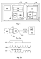
- Figure 2a schematically shows an XOR circuit 200, to whose inputs 202, 204 a frame synchronization signal and a line synchronization signal, taken for example from an image frame information transfer bus 124, are input, and from whose output 206 is obtained a combined signal that is input via the display interface 112 to the control system 104 of the display system.
- the frame synchronization signal and the line synchronization signal can naturally be taken from some other component of the display module, such as the display controller 118.
- the control system preferably comprises a counter 208 whose value is incremented by each short pulse received. In response to a long pulse, the counter is reset to zero. Since the durations of a long and a short pulse are significantly different, such observation logic is easy to implement. Consequently, the value of the counter always indicates the line of the screen that is being updated.
- Figure 2b schematically shows the combination of a frame synchronization signal and a line synchronization signal to form one signal by means of an XOR operation.
- the difference between pulse lengths in Figure 2b does not correspond to the real difference between pulse lengths, but the pulse of the frame synchronization signal with respect to the pulse of the line synchronization signal is shown considerably shorter than is real.
- Figure 2b clearly shows how several (in reality dozens or hundreds) short pulses SPn (SP1, SP2,...) are generated in a signal obtained from the output 206 during a time corresponding to one long pulse LP.
- Each short pulse SPn increments the value of the counter 208 during the update of an image frame until all lines of the image frame are updated to the screen and the counter has reached the maximum value determined according to the lines of the screen.
- the following long pulse LP zeroes the counter, and the update of the following image frame is observed from the start by means of the counter value, which again increases in response to short pulses observed.
- a combined signal is generated also in this case and comprises long pulses of a frame synchronization signal, during the duration of which several short pulses of a line synchronization signal occur. It is apparent to a person skilled in the art that to combine signals comprising pulses of considerably different lengths such that the original synchronization signals are easily reconstructed from the combined signal can be implemented in a variety of ways using different logical operations. Thus the implementation of the invention is not restricted to the above described OR and XOR operations.
- each line of the screen has to be updated before the image frame information to be formed on the corresponding line of the next image frame is stored in the frame buffer.
- This is preferably ensured by an interrupt being programmed in the counter, whereby the maximum value of the counter, the value being determined according to the number of lines on the screen, is used to control the control system to issue a command to the DMA controller to update a new image frame to the frame buffer at the same time as the counter receives a long pulse and is zeroed.
- the counter interrupt can be programmed to take place earlier, e.g. on line 150 on a 220-line screen.
- Advancing the update command of the DMA controller suitably allows interference in the update of image frames caused by possible delays on the transfer bus and, at the same time, the coincidence of the update of the screen and the update of the frame buffer on the same line to be avoided.
- the feedback of synchronization signals according to the invention is extremely simple to implement. If for example the above described OR or XOR operations are used to combine synchronization signals to form one signal, the necessary OR or XOR operation may be executed by adding any OR circuit or XOR circuit, respectively, known per se, to the display unit, to the inputs of which circuit a frame synchronization signal and a line synchronization signal are applied, and from whose output a combined signal is obtained that is applied to the display connector of the display interface, to which connector one pin is added, if necessary, to lead to signal to the control system. It is apparent to a person skilled in the art that OR and XOR circuits can be implemented in a variety of ways by combining different logics components.
- the display system and the method of updating image frames according to the invention are most preferably implemented in a mobile station, since the structurally simple implementation does not cause any essential increase in the size and weight of a mobile station, which is important for the design of mobile stations. Furthermore, processing signals and image frames in accordance with the invention does not require high processing power, and hence the batteries of mobile stations stay loaded longer.
Abstract
Description
- The invention relates to updating image frames on a screen, particularly on screens comprising memory.
- Display units are used for example in different computer systems and portable terminals, such as mobile stations, for displaying text and images to the user of the device. A display signal, typically comprising a display data signal and a synchronization signal, is input to the display unit. The display data signal comprises image frames that are distinguished from each other by means of a frame synchronization signal comprised by the synchronization signal. The synchronization signal also comprises a line synchronization signal for determining the separation of the lines comprised by one image frame.
- Image frames are displayed to the user of a device by means of a display screen that receives image frames at an encoding rate that thus determines the number of image frames received in a time unit. Image frames are updated on the screen at a frequency called screen refresh rate. For each display unit, the manufacturer typically defines a target refresh rate that is determined according to the properties of the screen and the interfaces associated therewith. Since the costs of a display unit typically have to be kept within given limits, the above properties also set a maximum value for the target refresh rate. This may lead to a situation where the refresh rate to be used is lower than the encoding rate at which the display unit receives image frames. In this case the display unit has to convert the frame frequency by adapting the image frames received at the encoding rate to be displayed on the screen at the refresh rate.
- Modern display units, particularly suitable for displaying moving image, such as video or various games, typically comprise memory for buffering image frames before the image frames are displayed on the screen. One image frame can typically be stored in the available buffer memory, allowing the frame frequency to be converted by reading the data comprised by the stored image frame and updating it to the screen at the refresh rate used.
- The problem in the above arrangement is the limited size of the buffer memory available in display units, which easily causes what is known as tearing to the image displayed on the screen, i.e. one part of the image displayed on the screen is composed of one image frame and another part of another image frame. On the screen this is visible as flashing lines or breaking in a laterally moving object. Tearing results from a new image frame being stored in the buffer memory before the previous image frame is entirely updated on the screen.
- To avoid tearing, the display unit could use a larger buffer memory having sufficient capacity for storing for example two image frames, ensuring that a new image frame would not be stored onto a image frame to be updated to the screen and still residing in the memory before the previous image frame is entirely updated to the screen. However, a larger buffer memory causes extra costs and the space it requires becomes a problem particularly in small devices, such as mobile stations. This means that a larger buffer memory would have to be integrated into the same IC circuit together with other signal-generating components, which may be impossible to implement sufficiently cost-effectively.
- Various software-based solutions are also known for converting the frame frequency, in which the control system of the display unit converts image frames received at the encoding rate into the refresh rate in accordance with instructions given by the microprocessor. One such method is known from US 6,054,980. However, the drawback of such methods is consumption of processing power and memory.
- The object of the invention is thus to provide a method and an apparatus implementing the method so as to avoid the above problems. The objects of the invention are achieved with a method, a system and a mobile station characterized by what is stated in the independent claims. The preferred embodiments of the invention are disclosed in the dependent claims.
- The invention is based on coupling synchronization signals from an image frame to be displayed on the screen also to the control system, allowing the control system to be timed on the basis of synchronization signals, particularly the pulses comprised thereby, to input a new image frame to the frame buffer such that the new image frame is not stored onto a image frame being updated to the screen. The synchronization signals are used to control the storage of a new image frame in the frame buffer such that each line of the screen is updated before the frame information to be created on the corresponding line of the following image frame is stored in the frame buffer.
- In accordance with a preferred embodiment, feedback synchronization signals are combined to form one signal, allowing the control system to interpret both synchronization signals correctly from said one signal. The synchronization signals are preferably combined to form one signal by means of a logic OR or XOR (Exclusive OR) operation.
- The advantage of the method and system of the invention is the avoidance of tearing and the ability to ensure the timely update of image frames to the screen. A further advantage is that updating the frame buffer on the basis of synchronization signals does not consume the processing power or memory of the control system since no special program code is needed to carry out the conversion of the frame frequency. Still another advantage is the ability to utilize the existing frame buffer of the display unit; no larger buffer memory is needed for the simultaneous storage of several image frames. A further advantage is that the feedback of synchronization signals according to the invention is extremely simple to implement.
- In the following, the invention will be described in greater detail in connection with preferred embodiments with reference to the accompanying drawings, in which
- Figure 1 is a block diagram of the structure of a display system;
- Figure 2a is a block diagram of coupling synchronization signals to the control system of a display system according to a preferred embodiment of the invention; and
- Figure 2b shows the combination of synchronization signals to form one signal according to a preferred embodiment of the invention.
-
- The structure of a display system, used typically in mobile stations, is described next with reference to Figure 1. However, the invention is not limited only to displays of mobile stations, but is applicable to any display unit using frame and line synchronization signals to separate image frames and the lines comprised by them.
- In Figure 1 a
display system 101 integrated into amobile station 100 comprises amemory 102 for storing and inputting image frame information to be displayed to acontrol system 104. Thecontrol system 104 comprises functionalities that are associated with editing image frame information and can be implemented for example as part of the functionalities of the mobile station's master control unit 106 (MCU) and digital signal processor 108 (DSP). Image frames are updated from thememory 102 to adisplay unit 116 by means of a direct memory access controller 110 (DMA), whereby theDMA controller 110 retrieves image frame information from thememory 102 and transfers it directly via adisplay interface 112 to the display unit without theMCU 106 or theDSP 108 issuing commands to transfer the image frame information. The MCU 106 only determines the speed for theDMA controller 110, that is, how many image frames are to be transferred in a time unit, i.e. the encoding rate. Accordingly, the DMA controller inputs a continuous data flow comprising image frames from thememory 102 to thedisplay unit 116. In addition, thecontrol system 104 may comprise agraphics accelerator 114 for adapting two-dimensional or three-dimensional graphics as suitable as possible for the properties of thedisplay unit 116. - The
display unit 116 comprises adisplay interface 112, adisplay controller 118 and aframe buffer 120 typically integrated into it for buffering image frames before they are displayed on a screen. Thedisplay unit 116 also comprises ascreen 122 and abus 124 for transferring image frame information from theframe buffer 120 to thescreen 122. Typically one image frame at a time is stored in the frame buffer, and the image frame is updated to thescreen 122 at the refresh rate set to thedisplay controller 118. - The image frame information to be input to the screen comprises a display data signal and a synchronization signal. The display data signal comprises image frames that are distinguished from each other by means of a frame synchronization signal comprised by the synchronization signal. The synchronization signal also comprises a line synchronization signal for determining the mutual separation of the lines comprised by one image frame. A pulse comprised by the frame synchronization signal is transmitted after each image frame, the pulse of the frame synchronization signal indicating the start of the update of the following image frame to the screen. A pulse comprised by the line synchronization signal is transmitted after each line feed of an image frame, the pulse of the line synchronization signal indicating the start of the update of the following line of the image frame to the screen. Depending on the display unit, the length of the pulse of a frame synchronization signal is typically about 2 to 6 times the time taken up by the update of one line. The length of the pulse of a line synchronization signal is a fraction of the time taken up by the update of one line. Consequently, the pulse of a frame synchronization signal is dozens or hundreds of times longer than the pulse of a line synchronization signal.
- In accordance with the invention, the above synchronization signals and their pulses can be utilized to avoid tearing on the screen. In accordance with the invention, said synchronization signals are led by feedback to the control system of the display system, particularly to the MCU, from which a control command, generated on the basis of the synchronization signals, is further transferred to the DMA controller for storing a new image frame in the frame buffer. Said synchronization signals thus comprise information on the progress of the update of the screen, allowing a new image frame to be stored in the frame buffer at precisely the right moment, thus preventing a new image frame from being stored in the frame buffer onto the image frame to be updated on the screen until the previous image frame is completely updated to the screen. This preferably avoids tearing and ensures timely update of image frames to the screen. A further advantage is that updating the frame buffer on the basis of synchronization signals does not use up processing power of the control system or memory, since no special program code is needed to change the frame frequency.
- Image frames can also be updated to the frame buffer according to the invention in a display system not comprising a DMA controller. In this case image frames are updated from the
memory 102 to thedisplay unit 116 with the DSP, which is controlled by control commands transmitted by the MCU. Part of said control commands, in turn, is preferably formed from the feedback synchronization signals in the above-described manner. However, such an arrangement loads the DSP significantly more than an image frame update carried out by means of a DMA controller. - In accordance with a preferred embodiment of the invention, the synchronization signals may be fed back to the control system as one signal, allowing the control system to interpret correctly both synchronization signals from said one signal. Since the lengths of the pulses comprised by the synchronization signals, i.e. the frame synchronization signal and the line synchronization signal, are notably different, the synchronization signals can be combined to form one signal by means of a logic OR or XOR (Exclusive OR) operation, for example. Such a combined signal thus comprises long pulses of a frame synchronization signal, during the duration of which several dozens or hundreds of short pulses of a line synchronization signal occur. From such a signal, the control system of the display system easily reconstructs the original synchronization signals, on the basis of which the update of the frame buffer can be synchronized suitable for the update of the screen.
- This embodiment is illustrated in Figures 2a and 2b. Figure 2a schematically shows an
XOR circuit 200, to whoseinputs 202, 204 a frame synchronization signal and a line synchronization signal, taken for example from an image frameinformation transfer bus 124, are input, and from whoseoutput 206 is obtained a combined signal that is input via thedisplay interface 112 to thecontrol system 104 of the display system. The frame synchronization signal and the line synchronization signal can naturally be taken from some other component of the display module, such as thedisplay controller 118. The control system preferably comprises acounter 208 whose value is incremented by each short pulse received. In response to a long pulse, the counter is reset to zero. Since the durations of a long and a short pulse are significantly different, such observation logic is easy to implement. Consequently, the value of the counter always indicates the line of the screen that is being updated. - Figure 2b schematically shows the combination of a frame synchronization signal and a line synchronization signal to form one signal by means of an XOR operation. By way of illustration, the difference between pulse lengths in Figure 2b does not correspond to the real difference between pulse lengths, but the pulse of the frame synchronization signal with respect to the pulse of the line synchronization signal is shown considerably shorter than is real. Figure 2b clearly shows how several (in reality dozens or hundreds) short pulses SPn (SP1, SP2,...) are generated in a signal obtained from the
output 206 during a time corresponding to one long pulse LP. Each short pulse SPn increments the value of thecounter 208 during the update of an image frame until all lines of the image frame are updated to the screen and the counter has reached the maximum value determined according to the lines of the screen. The following long pulse LP zeroes the counter, and the update of the following image frame is observed from the start by means of the counter value, which again increases in response to short pulses observed. - The above described combination of synchronization signals can be implemented in the same way by means of an OR operation, for example. A combined signal is generated also in this case and comprises long pulses of a frame synchronization signal, during the duration of which several short pulses of a line synchronization signal occur. It is apparent to a person skilled in the art that to combine signals comprising pulses of considerably different lengths such that the original synchronization signals are easily reconstructed from the combined signal can be implemented in a variety of ways using different logical operations. Thus the implementation of the invention is not restricted to the above described OR and XOR operations.
- To avoid tearing, each line of the screen has to be updated before the image frame information to be formed on the corresponding line of the next image frame is stored in the frame buffer. This is preferably ensured by an interrupt being programmed in the counter, whereby the maximum value of the counter, the value being determined according to the number of lines on the screen, is used to control the control system to issue a command to the DMA controller to update a new image frame to the frame buffer at the same time as the counter receives a long pulse and is zeroed. In case a security margin is needed in the update of the frame buffer, owing to a
slow display interface 112, for example, the counter interrupt can be programmed to take place earlier, e.g. on line 150 on a 220-line screen. Advancing the update command of the DMA controller suitably allows interference in the update of image frames caused by possible delays on the transfer bus and, at the same time, the coincidence of the update of the screen and the update of the frame buffer on the same line to be avoided. - The feedback of synchronization signals according to the invention is extremely simple to implement. If for example the above described OR or XOR operations are used to combine synchronization signals to form one signal, the necessary OR or XOR operation may be executed by adding any OR circuit or XOR circuit, respectively, known per se, to the display unit, to the inputs of which circuit a frame synchronization signal and a line synchronization signal are applied, and from whose output a combined signal is obtained that is applied to the display connector of the display interface, to which connector one pin is added, if necessary, to lead to signal to the control system. It is apparent to a person skilled in the art that OR and XOR circuits can be implemented in a variety of ways by combining different logics components.
- The display system and the method of updating image frames according to the invention are most preferably implemented in a mobile station, since the structurally simple implementation does not cause any essential increase in the size and weight of a mobile station, which is important for the design of mobile stations. Furthermore, processing signals and image frames in accordance with the invention does not require high processing power, and hence the batteries of mobile stations stay loaded longer.
- It is apparent to a person skilled in the art that, as technology advances, the basic idea of the invention can be implemented in a variety of ways. The invention and its embodiments are thus not limited to the above examples, but may vary within the scope of the claims.
Claims (13)
- A method of updating image frames on a screen of a display system, in which method image frames comprising a frame synchronization signal and a line synchronization signal are transferred in the display system from a control system to a display unit comprising a screen for displaying image frames, a transfer bus for transferring image frames to the screen, a frame buffer for buffering the image frames before the image frames are transferred via the transfer bus to the screen and for receiving image frames of the display interface from the control system to the frame buffer, characterized by
coupling said frame synchronization signal and line synchronization signal to said control system from the frame image to be updated to the screen and
timing said control system on the basis of pulses comprised by said frame synchronization signal and line synchronization signal to input a new image frame to the frame buffer such that the new image frame is not stored onto said image frame to be updated to the screen. - A method as claimed in claim 1, characterized by
combining said frame synchronization signal and line synchronization signal to form one timing signal,
coupling said timing signal to the control system and
detecting said frame synchronization signal and line synchronization signal from said timing signal in the control system. - A method as claimed in claim 2, characterized by
combining said frame synchronization signal and line synchronization signal by means of an XOR circuit. - A method as claimed in claim 2, characterized by
combining said frame synchronization signal and line synchronization signal by means of an OR circuit. - A method as claimed in any one of claims 1 to 4, characterized by
timing said control system with a counter, whose counter value is incremented by one in response to a received pulse of a line synchronization signal, and which is zeroed in response to a received pulse of a frame synchronization signal. - A method as claimed in claim 5, characterized by
inputting image frames from said control system via the display interface to the frame buffer by means of a DMA controller and
programming an interrupt to take place in said counter at most at the maximum value of the counter, in response to which value the DMA controller is controlled to input a new image frame to the frame buffer. - A display system on whose display screen image frames are arranged to be updated and comprise
a display data signal comprising image information,
a frame synchronization signal for distinguishing successive image frames from each other and
a line synchronization signal for distinguishing successive lines in an image frame from each other;
said display system comprises
a display unit comprising a display screen for displaying image frames, a transfer bus for transferring image frames to the screen, a frame buffer for buffering the image frames before the image frames are transferred via the transfer bus to the screen at a refresh rate, and a display interface for receiving the image frames to the frame buffer and
a control system arranged to input image frames via the display interface to the frame buffer at an encoding rate, characterized in that the display system comprises
coupling means for coupling said frame synchronization signal and line synchronization signal from an image frame to be updated to the screen to said control system and
timing means for timing said control system on the basis of pulses comprised by said frame synchronization signal and line synchronization signal to input a new image frame to the frame buffer such that the new image frame is not stored onto said image frame to be updated to the screen. - A display system as claimed in claim 7, characterized in that
said coupling means are arranged to combine said frame synchronization signal and line synchronization signal to form one timing signal that is arranged to be coupled to the control system and
the control system is arranged to detect said frame synchronization signal and line synchronization signal from said timing signal. - A display system as claimed in claim 8, characterized in that
said coupling means comprise an XOR circuit for combining said frame synchronization signal and line synchronization signal. - A display system as claimed in claim 8, characterized in that
said coupling means comprise an OR circuit for combining said frame synchronization signal and line synchronization signal. - A display system as claimed in any one of claims 7 to 10, characterized in that
said timing means comprise a counter arranged to increment the counter value by one in response to a received pulse of a line synchronization signal, and to zero the counter value in response to a received pulse of a frame synchronization signal. - A display system as claimed in claim 11, characterized in that
said control system comprises a DMA controller arranged to input image frames via the display interface to the frame buffer and
an interrupt is programmed to take place in said counter at most at the maximum value of the counter, in response to which value the DMA controller is controlled to input a new image frame to the frame buffer. - A mobile station, characterized in that it comprises a display system as claimed in any one of claims 7 to 12.
Applications Claiming Priority (2)
| Application Number | Priority Date | Filing Date | Title |
|---|---|---|---|
| FI20002649A FI115802B (en) | 2000-12-04 | 2000-12-04 | Refresh the photo frames on the memory display |
| FI20002649 | 2000-12-04 |
Publications (3)
| Publication Number | Publication Date |
|---|---|
| EP1217602A2 true EP1217602A2 (en) | 2002-06-26 |
| EP1217602A3 EP1217602A3 (en) | 2002-10-30 |
| EP1217602B1 EP1217602B1 (en) | 2004-06-23 |
Family
ID=8559633
Family Applications (1)
| Application Number | Title | Priority Date | Filing Date |
|---|---|---|---|
| EP01000582A Expired - Lifetime EP1217602B1 (en) | 2000-12-04 | 2001-10-31 | Updating image frames in a display device comprising a frame buffer |
Country Status (7)
| Country | Link |
|---|---|
| US (1) | US6816163B2 (en) |
| EP (1) | EP1217602B1 (en) |
| JP (2) | JP4188588B2 (en) |
| AT (1) | ATE269998T1 (en) |
| DE (1) | DE60103965T2 (en) |
| ES (1) | ES2222942T3 (en) |
| FI (1) | FI115802B (en) |
Cited By (28)
| Publication number | Priority date | Publication date | Assignee | Title |
|---|---|---|---|---|
| WO2004097789A1 (en) * | 2003-04-30 | 2004-11-11 | Nokia Corporation | Synchronization of image frame update |
| EP1544844A1 (en) * | 2003-12-17 | 2005-06-22 | Lg Electronics Inc. | System and method for controlling display of mobile terminal |
| KR100777683B1 (en) | 2006-11-15 | 2007-11-21 | (주)토마토엘에스아이 | Apparatus and method for interface of liquid crystal driver having sram for prevention of display distortion |
| EP2013867A2 (en) * | 2006-04-20 | 2009-01-14 | Cisco Technology, Inc. | Latency reduction in a display device |
| US7710450B2 (en) | 2006-04-20 | 2010-05-04 | Cisco Technology, Inc. | System and method for dynamic control of image capture in a video conference system |
| EP2479920A3 (en) * | 2004-11-24 | 2012-09-05 | Qualcomm Incorporated | Methods and systems for updating a buffer |
| US8539119B2 (en) | 2004-11-24 | 2013-09-17 | Qualcomm Incorporated | Methods and apparatus for exchanging messages having a digital data interface device message format |
| US8606946B2 (en) | 2003-11-12 | 2013-12-10 | Qualcomm Incorporated | Method, system and computer program for driving a data signal in data interface communication data link |
| US8611215B2 (en) | 2005-11-23 | 2013-12-17 | Qualcomm Incorporated | Systems and methods for digital data transmission rate control |
| US8625625B2 (en) | 2004-03-10 | 2014-01-07 | Qualcomm Incorporated | High data rate interface apparatus and method |
| US8630305B2 (en) | 2004-06-04 | 2014-01-14 | Qualcomm Incorporated | High data rate interface apparatus and method |
| US8635358B2 (en) | 2003-09-10 | 2014-01-21 | Qualcomm Incorporated | High data rate interface |
| US8650304B2 (en) | 2004-06-04 | 2014-02-11 | Qualcomm Incorporated | Determining a pre skew and post skew calibration data rate in a mobile display digital interface (MDDI) communication system |
| US8667363B2 (en) | 2004-11-24 | 2014-03-04 | Qualcomm Incorporated | Systems and methods for implementing cyclic redundancy checks |
| US8670457B2 (en) | 2003-12-08 | 2014-03-11 | Qualcomm Incorporated | High data rate interface with improved link synchronization |
| US8681817B2 (en) | 2003-06-02 | 2014-03-25 | Qualcomm Incorporated | Generating and implementing a signal protocol and interface for higher data rates |
| US8687658B2 (en) | 2003-11-25 | 2014-04-01 | Qualcomm Incorporated | High data rate interface with improved link synchronization |
| US8692839B2 (en) | 2005-11-23 | 2014-04-08 | Qualcomm Incorporated | Methods and systems for updating a buffer |
| US8694663B2 (en) | 2001-09-06 | 2014-04-08 | Qualcomm Incorporated | System for transferring digital data at a high rate between a host and a client over a communication path for presentation to a user |
| US8692838B2 (en) | 2004-11-24 | 2014-04-08 | Qualcomm Incorporated | Methods and systems for updating a buffer |
| US8694652B2 (en) | 2003-10-15 | 2014-04-08 | Qualcomm Incorporated | Method, system and computer program for adding a field to a client capability packet sent from a client to a host |
| US8705521B2 (en) | 2004-03-17 | 2014-04-22 | Qualcomm Incorporated | High data rate interface apparatus and method |
| US8705571B2 (en) | 2003-08-13 | 2014-04-22 | Qualcomm Incorporated | Signal interface for higher data rates |
| US8723705B2 (en) | 2004-11-24 | 2014-05-13 | Qualcomm Incorporated | Low output skew double data rate serial encoder |
| US8730069B2 (en) | 2005-11-23 | 2014-05-20 | Qualcomm Incorporated | Double data rate serial encoder |
| US8745251B2 (en) | 2000-12-15 | 2014-06-03 | Qualcomm Incorporated | Power reduction system for an apparatus for high data rate signal transfer using a communication protocol |
| US8756294B2 (en) | 2003-10-29 | 2014-06-17 | Qualcomm Incorporated | High data rate interface |
| US8873584B2 (en) | 2004-11-24 | 2014-10-28 | Qualcomm Incorporated | Digital data interface device |
Families Citing this family (10)
| Publication number | Priority date | Publication date | Assignee | Title |
|---|---|---|---|---|
| US7268755B2 (en) * | 2003-03-25 | 2007-09-11 | Intel Corporation | Architecture for smart LCD panel interface |
| EP1503331A2 (en) * | 2003-07-31 | 2005-02-02 | Matsushita Electric Industrial Co., Ltd. | Display data transfer apparatus and method |
| US9359481B2 (en) | 2003-11-26 | 2016-06-07 | Owens Corning Intellectual Capital, Llc | Thermoplastic foams and method of forming them using nano-graphite |
| US7644309B2 (en) * | 2005-05-20 | 2010-01-05 | Nokia Corporation | Recovering a hardware module from a malfunction |
| US8248387B1 (en) * | 2008-02-12 | 2012-08-21 | Microsoft Corporation | Efficient buffering of data frames for multiple clients |
| US8947420B2 (en) | 2011-05-27 | 2015-02-03 | Nokia Corporation | Processing image content for content motion or touch input |
| US9317892B2 (en) * | 2011-12-28 | 2016-04-19 | Intel Corporation | Method and device to augment volatile memory in a graphics subsystem with non-volatile memory |
| US8797340B2 (en) * | 2012-10-02 | 2014-08-05 | Nvidia Corporation | System, method, and computer program product for modifying a pixel value as a function of a display duration estimate |
| DE102013219581B4 (en) * | 2012-10-02 | 2016-11-24 | Nvidia Corporation | Apparatus, method and computer program product for providing dynamic display refreshment |
| CN114489545B (en) * | 2022-01-28 | 2022-08-02 | 广州文石信息科技有限公司 | Screen updating request scanning method and device, storage medium and related equipment |
Citations (6)
| Publication number | Priority date | Publication date | Assignee | Title |
|---|---|---|---|---|
| US4498098A (en) * | 1982-06-02 | 1985-02-05 | Digital Equipment Corporation | Apparatus for combining a video signal with graphics and text from a computer |
| FR2570566A1 (en) * | 1984-09-14 | 1986-03-21 | Micro Inf Video Ste Int | Method of overlaying images and expansion module which can be fitted to a home microcomputer implementing such a method |
| EP0525986A2 (en) * | 1991-07-26 | 1993-02-03 | Sun Microsystems, Inc. | Apparatus for fast copying between frame buffers in a double buffered output display system |
| US5555027A (en) * | 1991-01-29 | 1996-09-10 | Seiko Epson Corp. | Video processor for enlarging and contracting an image in a vertical direction |
| US5861879A (en) * | 1995-09-29 | 1999-01-19 | Sanyo Electric Co., Ltd. | Video signal processing device for writing and reading a video signal with respect to a memory according to different clocks, while preventing a write/read address pass-by in the memory |
| EP1143331A2 (en) * | 2000-04-07 | 2001-10-10 | Sony Corporation | Image procesing apparatus and method of the same, and display apparatus using the image processing apparatus |
Family Cites Families (14)
| Publication number | Priority date | Publication date | Assignee | Title |
|---|---|---|---|---|
| JPS6053940B2 (en) | 1978-05-19 | 1985-11-28 | 株式会社東京放送 | Write prohibition control circuit in frame synchronizer |
| JPH079569B2 (en) * | 1983-07-01 | 1995-02-01 | 株式会社日立製作所 | Display controller and graphic display device using the same |
| DE69114825T2 (en) * | 1990-12-21 | 1996-08-08 | Sun Microsystems Inc | Method and device for increasing the processing speed of a display system with double buffer memory. |
| US5243447A (en) | 1992-06-19 | 1993-09-07 | Intel Corporation | Enhanced single frame buffer display system |
| JPH06186939A (en) * | 1992-12-16 | 1994-07-08 | Yamaha Corp | Display controller |
| WO1996007175A1 (en) | 1994-08-31 | 1996-03-07 | S3 Incorporated | Apparatus for correction of video tearing |
| US5821910A (en) * | 1995-05-26 | 1998-10-13 | National Semiconductor Corporation | Clock generation circuit for a display controller having a fine tuneable frame rate |
| JPH0934428A (en) * | 1995-07-25 | 1997-02-07 | Hitachi Ltd | Method and device for displaying image |
| JP3149810B2 (en) * | 1997-03-25 | 2001-03-26 | 日本電気株式会社 | Image processing device |
| US6054980A (en) | 1999-01-06 | 2000-04-25 | Genesis Microchip, Corp. | Display unit displaying images at a refresh rate less than the rate at which the images are encoded in a received display signal |
| US6366572B1 (en) * | 1999-02-04 | 2002-04-02 | Senora Trading Company | Wireless communication system with symmetric communication protocol |
| US6581164B1 (en) * | 2000-01-03 | 2003-06-17 | Conexant Systems, Inc. | System for adjusting clock frequency based upon amount of unread data stored in sequential memory when reading a new line of data within a field of data |
| JP3611511B2 (en) * | 2000-09-27 | 2005-01-19 | 三菱電機株式会社 | Matrix type display device, image data display method, and portable information terminal device |
| JP3674488B2 (en) * | 2000-09-29 | 2005-07-20 | セイコーエプソン株式会社 | Display control method, display controller, display unit, and electronic device |
-
2000
- 2000-12-04 FI FI20002649A patent/FI115802B/en not_active IP Right Cessation
-
2001
- 2001-10-31 DE DE60103965T patent/DE60103965T2/en not_active Expired - Lifetime
- 2001-10-31 EP EP01000582A patent/EP1217602B1/en not_active Expired - Lifetime
- 2001-10-31 ES ES01000582T patent/ES2222942T3/en not_active Expired - Lifetime
- 2001-10-31 AT AT01000582T patent/ATE269998T1/en not_active IP Right Cessation
- 2001-12-04 US US10/005,061 patent/US6816163B2/en not_active Expired - Lifetime
- 2001-12-04 JP JP2001370081A patent/JP4188588B2/en not_active Expired - Fee Related
-
2008
- 2008-06-12 JP JP2008154549A patent/JP2008268971A/en active Pending
Patent Citations (6)
| Publication number | Priority date | Publication date | Assignee | Title |
|---|---|---|---|---|
| US4498098A (en) * | 1982-06-02 | 1985-02-05 | Digital Equipment Corporation | Apparatus for combining a video signal with graphics and text from a computer |
| FR2570566A1 (en) * | 1984-09-14 | 1986-03-21 | Micro Inf Video Ste Int | Method of overlaying images and expansion module which can be fitted to a home microcomputer implementing such a method |
| US5555027A (en) * | 1991-01-29 | 1996-09-10 | Seiko Epson Corp. | Video processor for enlarging and contracting an image in a vertical direction |
| EP0525986A2 (en) * | 1991-07-26 | 1993-02-03 | Sun Microsystems, Inc. | Apparatus for fast copying between frame buffers in a double buffered output display system |
| US5861879A (en) * | 1995-09-29 | 1999-01-19 | Sanyo Electric Co., Ltd. | Video signal processing device for writing and reading a video signal with respect to a memory according to different clocks, while preventing a write/read address pass-by in the memory |
| EP1143331A2 (en) * | 2000-04-07 | 2001-10-10 | Sony Corporation | Image procesing apparatus and method of the same, and display apparatus using the image processing apparatus |
Cited By (42)
| Publication number | Priority date | Publication date | Assignee | Title |
|---|---|---|---|---|
| US8745251B2 (en) | 2000-12-15 | 2014-06-03 | Qualcomm Incorporated | Power reduction system for an apparatus for high data rate signal transfer using a communication protocol |
| US8694663B2 (en) | 2001-09-06 | 2014-04-08 | Qualcomm Incorporated | System for transferring digital data at a high rate between a host and a client over a communication path for presentation to a user |
| US8812706B1 (en) | 2001-09-06 | 2014-08-19 | Qualcomm Incorporated | Method and apparatus for compensating for mismatched delays in signals of a mobile display interface (MDDI) system |
| KR100751861B1 (en) | 2003-04-30 | 2007-08-23 | 노키아 코포레이션 | Synchronization of image frame update |
| US7324114B2 (en) | 2003-04-30 | 2008-01-29 | Nokia Corporation | Synchronization of image frame update |
| WO2004097789A1 (en) * | 2003-04-30 | 2004-11-11 | Nokia Corporation | Synchronization of image frame update |
| US8700744B2 (en) | 2003-06-02 | 2014-04-15 | Qualcomm Incorporated | Generating and implementing a signal protocol and interface for higher data rates |
| US8681817B2 (en) | 2003-06-02 | 2014-03-25 | Qualcomm Incorporated | Generating and implementing a signal protocol and interface for higher data rates |
| US8705579B2 (en) | 2003-06-02 | 2014-04-22 | Qualcomm Incorporated | Generating and implementing a signal protocol and interface for higher data rates |
| US8705571B2 (en) | 2003-08-13 | 2014-04-22 | Qualcomm Incorporated | Signal interface for higher data rates |
| US8635358B2 (en) | 2003-09-10 | 2014-01-21 | Qualcomm Incorporated | High data rate interface |
| US8719334B2 (en) | 2003-09-10 | 2014-05-06 | Qualcomm Incorporated | High data rate interface |
| US8694652B2 (en) | 2003-10-15 | 2014-04-08 | Qualcomm Incorporated | Method, system and computer program for adding a field to a client capability packet sent from a client to a host |
| US8756294B2 (en) | 2003-10-29 | 2014-06-17 | Qualcomm Incorporated | High data rate interface |
| US8606946B2 (en) | 2003-11-12 | 2013-12-10 | Qualcomm Incorporated | Method, system and computer program for driving a data signal in data interface communication data link |
| US8687658B2 (en) | 2003-11-25 | 2014-04-01 | Qualcomm Incorporated | High data rate interface with improved link synchronization |
| US8670457B2 (en) | 2003-12-08 | 2014-03-11 | Qualcomm Incorporated | High data rate interface with improved link synchronization |
| US7714871B2 (en) | 2003-12-17 | 2010-05-11 | Lg Electronics Inc. | System and method for controlling display of mobile terminal |
| EP1544844A1 (en) * | 2003-12-17 | 2005-06-22 | Lg Electronics Inc. | System and method for controlling display of mobile terminal |
| US8625625B2 (en) | 2004-03-10 | 2014-01-07 | Qualcomm Incorporated | High data rate interface apparatus and method |
| US8730913B2 (en) | 2004-03-10 | 2014-05-20 | Qualcomm Incorporated | High data rate interface apparatus and method |
| US8669988B2 (en) | 2004-03-10 | 2014-03-11 | Qualcomm Incorporated | High data rate interface apparatus and method |
| US8705521B2 (en) | 2004-03-17 | 2014-04-22 | Qualcomm Incorporated | High data rate interface apparatus and method |
| US8630318B2 (en) | 2004-06-04 | 2014-01-14 | Qualcomm Incorporated | High data rate interface apparatus and method |
| US8630305B2 (en) | 2004-06-04 | 2014-01-14 | Qualcomm Incorporated | High data rate interface apparatus and method |
| US8650304B2 (en) | 2004-06-04 | 2014-02-11 | Qualcomm Incorporated | Determining a pre skew and post skew calibration data rate in a mobile display digital interface (MDDI) communication system |
| US8539119B2 (en) | 2004-11-24 | 2013-09-17 | Qualcomm Incorporated | Methods and apparatus for exchanging messages having a digital data interface device message format |
| US8723705B2 (en) | 2004-11-24 | 2014-05-13 | Qualcomm Incorporated | Low output skew double data rate serial encoder |
| US8699330B2 (en) | 2004-11-24 | 2014-04-15 | Qualcomm Incorporated | Systems and methods for digital data transmission rate control |
| US8873584B2 (en) | 2004-11-24 | 2014-10-28 | Qualcomm Incorporated | Digital data interface device |
| US8692838B2 (en) | 2004-11-24 | 2014-04-08 | Qualcomm Incorporated | Methods and systems for updating a buffer |
| US8667363B2 (en) | 2004-11-24 | 2014-03-04 | Qualcomm Incorporated | Systems and methods for implementing cyclic redundancy checks |
| EP2479920A3 (en) * | 2004-11-24 | 2012-09-05 | Qualcomm Incorporated | Methods and systems for updating a buffer |
| US8730069B2 (en) | 2005-11-23 | 2014-05-20 | Qualcomm Incorporated | Double data rate serial encoder |
| US8611215B2 (en) | 2005-11-23 | 2013-12-17 | Qualcomm Incorporated | Systems and methods for digital data transmission rate control |
| US8692839B2 (en) | 2005-11-23 | 2014-04-08 | Qualcomm Incorporated | Methods and systems for updating a buffer |
| CN101427303B (en) * | 2006-04-20 | 2011-03-23 | 思科技术公司 | Method and device for latency reduction in a display device |
| US7710450B2 (en) | 2006-04-20 | 2010-05-04 | Cisco Technology, Inc. | System and method for dynamic control of image capture in a video conference system |
| EP2013867A4 (en) * | 2006-04-20 | 2009-05-27 | Cisco Tech Inc | Latency reduction in a display device |
| EP2013867A2 (en) * | 2006-04-20 | 2009-01-14 | Cisco Technology, Inc. | Latency reduction in a display device |
| US8952974B2 (en) | 2006-04-20 | 2015-02-10 | Cisco Technology, Inc. | Latency reduction in a display device |
| KR100777683B1 (en) | 2006-11-15 | 2007-11-21 | (주)토마토엘에스아이 | Apparatus and method for interface of liquid crystal driver having sram for prevention of display distortion |
Also Published As
| Publication number | Publication date |
|---|---|
| FI115802B (en) | 2005-07-15 |
| DE60103965D1 (en) | 2004-07-29 |
| FI20002649A0 (en) | 2000-12-04 |
| US20020080134A1 (en) | 2002-06-27 |
| ES2222942T3 (en) | 2005-02-16 |
| JP2002236480A (en) | 2002-08-23 |
| US6816163B2 (en) | 2004-11-09 |
| EP1217602B1 (en) | 2004-06-23 |
| FI20002649A (en) | 2002-06-05 |
| JP4188588B2 (en) | 2008-11-26 |
| JP2008268971A (en) | 2008-11-06 |
| ATE269998T1 (en) | 2004-07-15 |
| EP1217602A3 (en) | 2002-10-30 |
| DE60103965T2 (en) | 2005-07-07 |
Similar Documents
| Publication | Publication Date | Title |
|---|---|---|
| US6816163B2 (en) | Updating image frames on a screen comprising memory | |
| CN101237548B (en) | Image pickup apparatus and control method, image display apparatus and control method | |
| US5943064A (en) | Apparatus for processing multiple types of graphics data for display | |
| CN102117594B (en) | Techniques for aligning frame data | |
| CN1981519B (en) | Method and system for displaying a sequence of image frames | |
| CN102117595B (en) | Techniques for aligning frame data | |
| US4689823A (en) | Digital image frame processor | |
| CN108449566A (en) | Video frame rate compensation is carried out by adjusting vertical blanking | |
| CN100361523C (en) | A real-time acquisition system for digital camera | |
| US7882380B2 (en) | Work based clock management for display sub-system | |
| CN104360511A (en) | MIPI module test method and test system realizing two modes | |
| CN110569208B (en) | Control circuit, signal control device, signal control method and system | |
| CN201548484U (en) | Universal multi-path digital image simulating source | |
| EP1160671A2 (en) | Host interface circuit | |
| CN112367537A (en) | Video acquisition-splicing-display system based on ZYNQ | |
| US5333259A (en) | Graphic information processing system having a RISC CPU for displaying information in a window | |
| KR100284420B1 (en) | Digital video capture board | |
| CN203561981U (en) | Embedded laser projector controller with MP3 audio output function | |
| KR100460994B1 (en) | High-bandwidth I/O device with direct memory access and method thereof | |
| CN209044332U (en) | Synchronous processing circuit, synchronization processing apparatus and System of Synchronous Processing | |
| CN117156073A (en) | Video data transmission device and system | |
| Qian et al. | Design of video acquisition identification system based on Zynq-7000 Soc Platform | |
| SU1176339A1 (en) | Interface for linking digital computer with image input device | |
| JPS6213690B2 (en) | ||
| KR20000015400A (en) | Bus controller for an inter-integrated circuit serial interface bus |
Legal Events
| Date | Code | Title | Description |
|---|---|---|---|
| PUAI | Public reference made under article 153(3) epc to a published international application that has entered the european phase |
Free format text: ORIGINAL CODE: 0009012 |
|
| AK | Designated contracting states |
Kind code of ref document: A2 Designated state(s): AT BE CH CY DE DK ES FI FR GB GR IE IT LI LU MC NL PT SE TR |
|
| AX | Request for extension of the european patent |
Free format text: AL;LT;LV;MK;RO;SI |
|
| PUAL | Search report despatched |
Free format text: ORIGINAL CODE: 0009013 |
|
| AK | Designated contracting states |
Kind code of ref document: A3 Designated state(s): AT BE CH CY DE DK ES FI FR GB GR IE IT LI LU MC NL PT SE TR |
|
| AX | Request for extension of the european patent |
Free format text: AL;LT;LV;MK;RO;SI |
|
| RIC1 | Information provided on ipc code assigned before grant |
Free format text: 7G 09G 5/393 A, 7G 09G 5/18 B, 7G 09G 1/16 B |
|
| 17P | Request for examination filed |
Effective date: 20030228 |
|
| 17Q | First examination report despatched |
Effective date: 20030328 |
|
| AKX | Designation fees paid |
Designated state(s): AT BE CH CY DE DK ES FI FR GB GR IE IT LI LU MC NL PT SE TR |
|
| GRAP | Despatch of communication of intention to grant a patent |
Free format text: ORIGINAL CODE: EPIDOSNIGR1 |
|
| GRAS | Grant fee paid |
Free format text: ORIGINAL CODE: EPIDOSNIGR3 |
|
| GRAA | (expected) grant |
Free format text: ORIGINAL CODE: 0009210 |
|
| AK | Designated contracting states |
Kind code of ref document: B1 Designated state(s): AT BE CH CY DE DK ES FI FR GB GR IE IT LI LU MC NL PT SE TR |
|
| PG25 | Lapsed in a contracting state [announced via postgrant information from national office to epo] |
Ref country code: CY Free format text: LAPSE BECAUSE OF FAILURE TO SUBMIT A TRANSLATION OF THE DESCRIPTION OR TO PAY THE FEE WITHIN THE PRESCRIBED TIME-LIMIT Effective date: 20040623 Ref country code: BE Free format text: LAPSE BECAUSE OF FAILURE TO SUBMIT A TRANSLATION OF THE DESCRIPTION OR TO PAY THE FEE WITHIN THE PRESCRIBED TIME-LIMIT Effective date: 20040623 Ref country code: FI Free format text: LAPSE BECAUSE OF FAILURE TO SUBMIT A TRANSLATION OF THE DESCRIPTION OR TO PAY THE FEE WITHIN THE PRESCRIBED TIME-LIMIT Effective date: 20040623 Ref country code: AT Free format text: LAPSE BECAUSE OF FAILURE TO SUBMIT A TRANSLATION OF THE DESCRIPTION OR TO PAY THE FEE WITHIN THE PRESCRIBED TIME-LIMIT Effective date: 20040623 Ref country code: TR Free format text: LAPSE BECAUSE OF FAILURE TO SUBMIT A TRANSLATION OF THE DESCRIPTION OR TO PAY THE FEE WITHIN THE PRESCRIBED TIME-LIMIT Effective date: 20040623 Ref country code: LI Free format text: LAPSE BECAUSE OF FAILURE TO SUBMIT A TRANSLATION OF THE DESCRIPTION OR TO PAY THE FEE WITHIN THE PRESCRIBED TIME-LIMIT Effective date: 20040623 Ref country code: CH Free format text: LAPSE BECAUSE OF FAILURE TO SUBMIT A TRANSLATION OF THE DESCRIPTION OR TO PAY THE FEE WITHIN THE PRESCRIBED TIME-LIMIT Effective date: 20040623 |
|
| REG | Reference to a national code |
Ref country code: GB Ref legal event code: FG4D |
|
| REG | Reference to a national code |
Ref country code: CH Ref legal event code: EP |
|
| REG | Reference to a national code |
Ref country code: IE Ref legal event code: FG4D |
|
| REF | Corresponds to: |
Ref document number: 60103965 Country of ref document: DE Date of ref document: 20040729 Kind code of ref document: P |
|
| PG25 | Lapsed in a contracting state [announced via postgrant information from national office to epo] |
Ref country code: GR Free format text: LAPSE BECAUSE OF FAILURE TO SUBMIT A TRANSLATION OF THE DESCRIPTION OR TO PAY THE FEE WITHIN THE PRESCRIBED TIME-LIMIT Effective date: 20040923 Ref country code: DK Free format text: LAPSE BECAUSE OF FAILURE TO SUBMIT A TRANSLATION OF THE DESCRIPTION OR TO PAY THE FEE WITHIN THE PRESCRIBED TIME-LIMIT Effective date: 20040923 |
|
| REG | Reference to a national code |
Ref country code: SE Ref legal event code: TRGR |
|
| PG25 | Lapsed in a contracting state [announced via postgrant information from national office to epo] |
Ref country code: LU Free format text: LAPSE BECAUSE OF NON-PAYMENT OF DUE FEES Effective date: 20041031 Ref country code: MC Free format text: LAPSE BECAUSE OF NON-PAYMENT OF DUE FEES Effective date: 20041031 |
|
| PG25 | Lapsed in a contracting state [announced via postgrant information from national office to epo] |
Ref country code: IE Free format text: LAPSE BECAUSE OF NON-PAYMENT OF DUE FEES Effective date: 20041101 |
|
| REG | Reference to a national code |
Ref country code: CH Ref legal event code: PL |
|
| REG | Reference to a national code |
Ref country code: ES Ref legal event code: FG2A Ref document number: 2222942 Country of ref document: ES Kind code of ref document: T3 |
|
| ET | Fr: translation filed | ||
| PLBE | No opposition filed within time limit |
Free format text: ORIGINAL CODE: 0009261 |
|
| STAA | Information on the status of an ep patent application or granted ep patent |
Free format text: STATUS: NO OPPOSITION FILED WITHIN TIME LIMIT |
|
| 26N | No opposition filed |
Effective date: 20050324 |
|
| REG | Reference to a national code |
Ref country code: IE Ref legal event code: MM4A |
|
| PG25 | Lapsed in a contracting state [announced via postgrant information from national office to epo] |
Ref country code: PT Free format text: LAPSE BECAUSE OF NON-PAYMENT OF DUE FEES Effective date: 20041123 |
|
| REG | Reference to a national code |
Ref country code: GB Ref legal event code: 732E Free format text: REGISTERED BETWEEN 20150910 AND 20150916 |
|
| REG | Reference to a national code |
Ref country code: DE Ref legal event code: R082 Ref document number: 60103965 Country of ref document: DE Representative=s name: COHAUSZ & FLORACK PATENT- UND RECHTSANWAELTE P, DE Ref country code: DE Ref legal event code: R081 Ref document number: 60103965 Country of ref document: DE Owner name: NOKIA TECHNOLOGIES OY, FI Free format text: FORMER OWNER: NOKIA CORP., 02610 ESPOO, FI |
|
| REG | Reference to a national code |
Ref country code: ES Ref legal event code: PC2A Owner name: NOKIA TECHNOLOGIES OY Effective date: 20151124 |
|
| REG | Reference to a national code |
Ref country code: NL Ref legal event code: PD Owner name: NOKIA TECHNOLOGIES OY; FI Free format text: DETAILS ASSIGNMENT: VERANDERING VAN EIGENAAR(S), OVERDRACHT; FORMER OWNER NAME: NOKIA CORPORATION Effective date: 20151111 |
|
| REG | Reference to a national code |
Ref country code: FR Ref legal event code: PLFP Year of fee payment: 16 |
|
| REG | Reference to a national code |
Ref country code: FR Ref legal event code: TP Owner name: NOKIA TECHNOLOGIES OY, FI Effective date: 20170109 |
|
| REG | Reference to a national code |
Ref country code: FR Ref legal event code: PLFP Year of fee payment: 17 |
|
| REG | Reference to a national code |
Ref country code: FR Ref legal event code: PLFP Year of fee payment: 18 |
|
| PGFP | Annual fee paid to national office [announced via postgrant information from national office to epo] |
Ref country code: FR Payment date: 20180913 Year of fee payment: 18 |
|
| PGFP | Annual fee paid to national office [announced via postgrant information from national office to epo] |
Ref country code: NL Payment date: 20181017 Year of fee payment: 18 |
|
| PGFP | Annual fee paid to national office [announced via postgrant information from national office to epo] |
Ref country code: DE Payment date: 20181016 Year of fee payment: 18 Ref country code: SE Payment date: 20181011 Year of fee payment: 18 |
|
| PGFP | Annual fee paid to national office [announced via postgrant information from national office to epo] |
Ref country code: GB Payment date: 20181031 Year of fee payment: 18 Ref country code: ES Payment date: 20181102 Year of fee payment: 18 Ref country code: IT Payment date: 20181018 Year of fee payment: 18 |
|
| REG | Reference to a national code |
Ref country code: DE Ref legal event code: R119 Ref document number: 60103965 Country of ref document: DE |
|
| REG | Reference to a national code |
Ref country code: NL Ref legal event code: MM Effective date: 20191101 |
|
| REG | Reference to a national code |
Ref country code: SE Ref legal event code: EUG |
|
| PG25 | Lapsed in a contracting state [announced via postgrant information from national office to epo] |
Ref country code: DE Free format text: LAPSE BECAUSE OF NON-PAYMENT OF DUE FEES Effective date: 20200501 |
|
| PG25 | Lapsed in a contracting state [announced via postgrant information from national office to epo] |
Ref country code: SE Free format text: LAPSE BECAUSE OF NON-PAYMENT OF DUE FEES Effective date: 20191101 Ref country code: NL Free format text: LAPSE BECAUSE OF NON-PAYMENT OF DUE FEES Effective date: 20191101 |
|
| GBPC | Gb: european patent ceased through non-payment of renewal fee |
Effective date: 20191031 |
|
| PG25 | Lapsed in a contracting state [announced via postgrant information from national office to epo] |
Ref country code: GB Free format text: LAPSE BECAUSE OF NON-PAYMENT OF DUE FEES Effective date: 20191031 Ref country code: IT Free format text: LAPSE BECAUSE OF NON-PAYMENT OF DUE FEES Effective date: 20191031 Ref country code: FR Free format text: LAPSE BECAUSE OF NON-PAYMENT OF DUE FEES Effective date: 20191031 |
|
| REG | Reference to a national code |
Ref country code: ES Ref legal event code: FD2A Effective date: 20210414 |
|
| PG25 | Lapsed in a contracting state [announced via postgrant information from national office to epo] |
Ref country code: ES Free format text: LAPSE BECAUSE OF NON-PAYMENT OF DUE FEES Effective date: 20191101 |