EP1237076A2 - Expert system for generating user interfaces - Google Patents
Expert system for generating user interfaces Download PDFInfo
- Publication number
- EP1237076A2 EP1237076A2 EP02004515A EP02004515A EP1237076A2 EP 1237076 A2 EP1237076 A2 EP 1237076A2 EP 02004515 A EP02004515 A EP 02004515A EP 02004515 A EP02004515 A EP 02004515A EP 1237076 A2 EP1237076 A2 EP 1237076A2
- Authority
- EP
- European Patent Office
- Prior art keywords
- user
- user interface
- expert system
- intention
- application
- Prior art date
- Legal status (The legal status is an assumption and is not a legal conclusion. Google has not performed a legal analysis and makes no representation as to the accuracy of the status listed.)
- Ceased
Links
Images


Classifications
-
- G—PHYSICS
- G06—COMPUTING; CALCULATING OR COUNTING
- G06F—ELECTRIC DIGITAL DATA PROCESSING
- G06F8/00—Arrangements for software engineering
- G06F8/30—Creation or generation of source code
- G06F8/38—Creation or generation of source code for implementing user interfaces
Definitions
- the present invention relates generally to expert systems and, more particularly, to an a piece of software that receives intentions of a user interface designer from an application and realizes the intentions by making decisions to generate user interfaces from a set of programmatic rules, which are based on knowledge of experts in the field of user interfaces as embodied in guidelines, conventions, and principles of user interface design.
- a user interface is a portion of a program or an operating system through which a user can instruct a computing device to accomplish a result and through which the device can convey information to the user.
- Examples of computing devices are computers, portable electronic devices such as telephones, and interactive television units. (Hereafter, the term computer is used to refer generally to all computing devices.)
- a graphical user interface is a user interface that makes use of a computer monitor or other type of display (such as a television) as an output device, and one or more input devices, typically a computer keyboard and a pointing device, such as a mouse, that affect the display.
- the computer displays information to the user in screens.
- a screen may take up the entire viewable area of the display, or may take up only a portion of the viewable area in the form of a window.
- Another example of a user interface is an audio user interface in which the user speaks to the computer through a microphone input device, and the computer responds via a speaker output device.
- Some user interfaces support multiple modes of interaction (e.g., graphical and audio).
- a collection of user interface routines may be stored in a library (not shown) resident in an operating system, such as the Microsoft Windows operating system 118 (hereafter, "Windows 118").
- an operating system such as the Microsoft Windows operating system 118 (hereafter, "Windows 118").
- Windows 118 the Microsoft Windows operating system 118
- To invoke a user interface routine in the library software programmers place a function call, which invokes a corresponding routine in the library, at an appropriate place in a program 116.
- the computer that is running the program 116 comes to the function call, the computer executes the function call and transforms the function call into a request for service from the corresponding user interface routine in the library.
- Each function call includes a set of input arguments.
- the input arguments are passed along to the corresponding user interface routine when the function call is executed by the computer.
- Each routine is designed to present a user interface from a particular template, such as a dialog box 120, which is a special window that solicits a response from a user.
- the input arguments provide information that may affect the presentation of the dialog box 120.
- Each function call has a one-to-one correspondence with a single template in one routine. There is an expectation that for each function call a precise instance of a particular template will appear. There can be no deviation since any deviation is considered a bug in Windows 118.
- FIGURES 1B-1E illustrate message boxes 124-130, which are a type of the dialog box 120.
- the template from which each message box is formed includes a title bar 102, which is a horizontal space at the top of the message box that contains the name of the message box, and a close button 104, which is a square button that is usually located in the right comer of the title bar with an x mark on it.
- the template for the message box also includes a screen 106 for containing messages as well as one or more buttons to allow the user to interact with the message box.
- the message box 124 in FIGURE 1B presents a message "Hello world!” to a user along with an OK button 108.
- the function call to create the FIGURE 1B message box 124 may be of a form: messageBox("Hello World!, OK), which is a function call having a name "messageBox" and two input arguments "Hello World! and "OK.”
- the FIGURE 1C message box 126 is similar to the FIGURE 1B message box 124, except that the FIGURE 1C message box 126 also includes a Cancel button 110.
- the function call to create the FIGURE 1C message box 126 may have a form: messageBox("Hello World!, OK_CANCEL).
- the function call to create the message box 128 may have the form: messageBox("Hello World!, YES_NO_CANCEL).
- the input arguments to the function call that creates the FIGURE 1E message box 130 includes a long string of text "Call me Ishmael" and the OK button 108.
- the user interface routine that corresponds to the function call that creates the FIGURE 1E message box 130 increases the vertical space of the FIGURE 1E message box 130 so as to accommodate the long string of text.
- a form of the function call to create the FIGURE 1E message box 130 include a signature, such as messageBox("Call me Ishmael --, OK).
- FIGURES 1B-1E illustrate that a the function call messageBox((7) is made from the program 116, a messageBox template in Windows 118 is used to create message boxes 124-130. Modifications to a message box template can be made by furnishing certain information through the input arguments to the function call messageBox(%), but a modified message box is still a kind of a message box, and no deviation will be made by Windows 118.
- User interfaces can be constructed directly in the programming languages used by software programmers as discussed above with reference to FIGURES 1A-1E, but are more often constructed using specialized user interface development tools.
- graphical user interfaces are often constructed using a tool called a forms package.
- a forms package typically presents the programmer with a screen (also called a form) that approximates what the user will see.
- the forms package allows the programmer to add individual graphical user interface controls (e.g., buttons, text entry boxes, list boxes) to the screen, and arrange the controls on the screen.
- the forms package also allows the programmer to indicate how the screen and its controls should react to user actions, such as when the user clicks on a button control with a mouse.
- the programmer defines these reactions explicitly by writing routines in computer code, and then connecting controls on the screen to those routines. Specific user events then trigger the execution of the associated code routines.
- a graphical user interface for a program may consist of one or many screens.
- Forms packages allow the programmer complete freedom in constructing user interfaces with whatever screens the programmer desires. However, with this freedom comes the opportunity to make many mistakes.
- the programmer may create a user interface that is too complex for its users to understand and use properly.
- the programmer may inadvertently create a user interface with bugs. An example of a bug is failing to handle correctly the entire range of possible input conditions.
- FIGURE 7 shows a type of screen in a graphical user interface, in which the user is asked to choose one of four items.
- a window 702 contains text 704 instructing the user to make a selection from the option buttons 706, 708, 710, and 712.
- option button 706 is shown selected. Only one of the option buttons 706, 708, 710, and 712 can be selected at a given time. The user selects one of the buttons, and then clicks an OK button 714 to indicate that he is finished. The user can also click a Cancel button 716 to indicate that he does not wish to make a selection.
- the controls on the screen shown in FIGURE 7 form a familiar pattern.
- Many programmers create screens that follow the pattern shown in FIGURE 7 even if the specific purpose of the screen is different.
- users of graphical user interfaces may become familiar with such patterns, thereby increasing their efficiency with a program. They may be able to more quickly learn new screens if the screens conform to patterns they have seen previously.
- Complicating the programmer's decision is that, at the time the programmer is writing the program, the programmer is typically unable to know the exact conditions under which the user interface will be used.
- a program may need to offer the user a list of choices where the number of choices varies greatly depending upon factors that change (e.g., the program needs to display a list of people currently connected to a computer network).
- the programmer is often forced to make decisions based on a theoretical or estimated range of values for such a factor.
- the decision made at the time of writing the program may result in a user interface that is inappropriate in practice.
- the present invention moves much of the burden of identifying and constructing an appropriate user interface pattern to an expert system, which is programmed to follow guidelines, conventions, and principles of user interface design.
- a programmer writes an application in a traditional manner, but does not need to create a complete user interface for the application. Instead, the programmer writes code to reflect his intentions for the purpose of the user interface and these pieces of code invoke the expert system, which completes the user interface of the application.
- the expert system generates an appropriate user interface on the fly and returns this interface to the application.
- the application then invokes this user interface, which controls user interaction.
- the user interface communicates with the application as necessary.
- the user interface eventually returns control to the application when the user interface receives some indication from the user's interaction.
- the expert system instead of generating the user interface on the fly, alternatively, the expert system generates and stores the user interface for later use during runtime of the application.
- the programmer can use the expert system to generate an application's entire user interface or just a portion of it.
- FIGURE 2 illustrates an example of a suitable computing system environment 200 on which the invention may be implemented.
- the computing system environment 200 is only one example of a suitable computing environment and is not intended to suggest any limitation as to the scope of use or functionality of the invention. Neither should the computing environment 200 be interpreted as having any dependency or requirement relating to any one or combination of the illustrated and described components.
- the invention is operational with numerous other general purpose or special purpose computing system environments or configurations.
- Examples of well-known computing systems, environments and/or configurations that may be suitable for use with the invention include, but are not limited to, personal computers, server computers, handheld or laptop devices, multiprocessor systems, microprocessor-based systems, set top boxes, programmable consumer electronics, network PCs, minicomputers, mainframe computers, distributed computing environments that include any of the above systems or devices, and the like.
- program modules include routines, programs, objects, components, data structures, etc., that perform particular tasks or implement particular abstract data types.
- the invention may also be practiced in distributed computing environments where tasks are performed by remote processing devices that are linked through a communications network.
- program modules may be located in both local and remote computer storage media, including memory storage devices.
- a system for implementing the invention includes a general purpose computing device in the form of a computer 210.
- Components of computer 210 may include, but are not limited to, a processing unit 220, a system memory 230, and a system bus 221 that couples various system components including the system memory to the processing unit 220.
- the system bus 221 may be any of several types of bus structures, including a memory bus or memory controller, a peripheral bus, and a local bus using any of a variety of bus architectures.
- bus architectures include Industry Standard Architecture (ISA) bus, Micro Channel Architecture (MCA) bus, Enhanced ISA (EISA) bus, Video Electronics Standards Association (VESA) local bus, and Peripheral Component Interconnect (PCI) bus, also known as Mezzanine bus.
- ISA Industry Standard Architecture
- MCA Micro Channel Architecture
- EISA Enhanced ISA
- VESA Video Electronics Standards Association
- PCI Peripheral Component Interconnect
- Computer 210 typically includes a variety of computer readable media.
- Computer readable media can be any available media that can be accessed by computer 210 and includes both volatile and nonvolatile media, removable and non-removable media.
- Computer readable media may comprise computer storage media and communication media.
- Computer storage media includes both volatile and nonvolatile, removable and non-removable media implemented in any method or technology for storage of information such as computer readable instructions, data structures, program modules or other data.
- Computer storage media includes, but is not limited to, RAM, ROM, EEPROM, flash memory or other memory technology, CD-ROM, digital versatile disks (DVD) or other optical disk storage, magnetic cassettes, magnetic tapes, magnetic disk storage or other magnetic storage devices, or any other computer storage media.
- Communication media typically embodies computer readable instructions, data structures, program modules or other data in a modulated data signal, such as a carrier wave or other transport mechanism that includes any information delivery media.
- modulated data signal means a signal that has one or more of its characteristics set or changed in such a manner as to encode information in the signal.
- communication media includes wired media, such as a wired network or direct-wired connection, and wireless media such as acoustic, RF infrared, and other wireless media. A combination of any of the above should also be included within the scope of computer readable media.
- the system memory 230 includes computer storage media in the form of volatile and/or nonvolatile memory such as read-only memory (ROM) 231 and random access memory (RAM) 232.
- ROM read-only memory
- RAM random access memory
- BIOS basic input/output system 233
- RAM 232 typically contains data and/or program modules that are immediately accessible, and/or presently being operated on, by processing unit 220.
- FIGURE 2 illustrates operating system 234, application programs 235, other program modules 236, and program data 237.
- the computer 210 may also include other removable/non-removable, volatile/nonvolatile computer storage media.
- FIGURE 2 illustrates the hard disk drive 241 that reads from or writes to non-removable, nonvolatile magnetic media, the magnetic disk drive 251 that reads from or writes to a removable, nonvolatile magnetic disk 252, and an optical disk drive 255 that reads from or writes to a removable, nonvolatile optical disk 256, such as a CD-ROM or other optical media.
- removable/non-removable, volatile/nonvolatile computer storage media that can be used in the exemplary operating environment include, but are not limited to, magnetic tape cassettes, flash memory cards, digital versatile disks, digital videotapes, solid state RAM, solid state ROM, and the like.
- the hard disk drive 241 is typically connected to the system bus 221 through a non-removable memory interface, such as interface 240, and the magnetic disk write 251 and optical disk drive 255 are typically connected to the system bus 221 by a removable memory interface, such as interface 250.
- hard disk drive 241 is illustrated as storing operating system 244, application programs 245, other program modules 246, and program data 247. Note that these components can either be the same as or different from operating system 234, application programs 235, other program modules 236, and program data 237. Operating system 244, application programs 245, other program modules 246, and program data 247 are given different numbers here to illustrate that, at a minimum, they are different copies.
- a user may enter commands and information into the computer 210 through input devices, such as a keyboard 262 and pointing device 261, commonly referred to as a mouse, trackball, or touch pad.
- Other input devices may include a microphone, joystick, game pad, satellite dish, scanner, or the like. These and other input devices are often connected to the processing unit 220 through a user input interface 260 that is coupled to the system bus, but may be connected by other interface and bus structures, such as a parallel port, game port, or universal serial bus (USB).
- a monitor 291 or other type of display device is also connected to the system bus 221 via an interface, such as a video interface 290.
- computers may also include other peripheral output devices, such as speakers 297 and printer 296, which may be connected through an input/output peripheral interface 295.
- the computer 210 may operate in a networked environment using logical connections to one or more remote computers, such as a remote computer 280.
- the remote computer 280 may be a personal computer, a server, a router, a network PC, a peer device, or other common network node, and typically includes many or all of the elements described above relative to the computer 210, although only a memory storage device 281 has been illustrated in FIGURE 2.
- the logical connections depicted in FIGURE 2 include a local area network (LAN) 271 and a wide area network (WAN) 273, but may also include other networks.
- LAN local area network
- WAN wide area network
- Such network environments are commonplace in offices, enterprise-wide computer networks, intranets, and the Internet.
- the computer 210 When used in a LAN networking environment, the computer 210 is connected to the LAN 271 through a network interface or adapter 270. When used in a WAN networking environment, the computer 210 typically includes a modem 272 or other means for establishing communications over the WAN 273, such as the Internet.
- the modem 272 which may be internal or external, may be connected to the system bus 221 via the input/output peripheral interface 295, or other appropriate mechanism.
- program modules depicted relative to the computer 210, or portions thereof, may be stored in the remote memory storage device.
- FIGURE 2 illustrates remote application programs 285 as residing on memory device 281. It will be appreciated that the network connections shown are for illustrative purposes only and other means of establishing a communications link between the computers may be used.
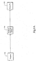
- FIGURE 3A depicts a computer 302 suitable for practicing the preferred embodiment of the present invention.
- An area of memory 304 contains an application 306 written by the programmer.
- This application 306 invokes an expert system 308.
- the expert system 308 considers information passed to it from the application 306 and possibly also examines external factors stored on a permanent storage device 312 or on another computer 320 connected via a network 318.
- the expert system 308 generates a user interface 310 and returns the user interface 310 to the application 306.
- the application 306 invokes the user interface 310 to interact with the user right after the user interface 310 is created or at runtime if the generated user interface 310 has been stored away.
- the user interface 310 controls this interaction by communicating information to the user via an output device 314 and receiving input from the user via an input device 316. When the interaction is complete, the user interface 310 returns any result of the interaction to the calling program 306.
- the programmer or a user interface designer begins the process of generating the user interface 310 by indicating the user interface goal or his intention to the expert system 308.
- FIGURE 3B illustrates in greater detail the communication of a user interface goal or an intention (hereafter, user interface goal(s) 324 or intention(s) 324) to the expert system 308.
- Intentions 324 are stored in the application 306.
- the application 306 may have an incomplete user interface.
- intentions 324 are communicated to the expert system 308 to generate the user interface 310, the incomplete user interface of the application 306 is completed.
- Many suitable techniques to implement intentions 324 can be used.
- One suitable technique includes storing intentions 324 on the application 306 as function calls. Each function call has a set of parameters 326 associated with it.
- Various kinds of user interface goals or intentions are possible, such as what sort of question to ask the user, what sort of information to communicate to the user, or what sort of task to have the user perform. Examples of such user interface goals or intentions include the following:
- the programmer can supply parameters 326 to the expert system 308 that further specify the programmer's intent, or otherwise assist the expert system 308 in generating a meaningful user interface.
- the expert system 308 may also require the programmer to supply some parameters 326 depending on the specified user interface goal or intention. Other parameters may be optional. Examples of parameters 326 include:
- the expert system 308 may also examine external factors available to it in making a decision about which user interface is most appropriate. These external factors might include:
- the user interface generated by the expert system 308 for an intention may be radically different under different input conditions - or even under identical input conditions (because external factors may have changed). That is, the expert system 308 may offer the programmer no guarantee it will generate the same user interface if invoked multiple times with the same intention and the same set of parameters 326.
- the generated user interface 310 may include a single screen, a sequence of multiple screens, or include no screens at all.
- screen is used generally to refer to either the entire visible display area on an output device, or a window contained within a larger display, or a portion of a window.
- the generated user interface can include screens encapsulated in pagefunctions, which are described in U.S. Application No. , filed February 27, 2002, titled “PAGEFUNCTION ARCHITECTURAL SOFTWARE FRAMEWORK,” and which is incorporated herein by reference (Attorney Docket No. MSFT-1-18569).
- the controls on the screens may vary from invocation to invocation, as may the controls' attributes: their labels, positions, sizes, contained values, etc.
- the expert system 308 may also generate other types of user interfaces other than graphical user interfaces (e.g., audio user interfaces).
- the expert system 308 is implemented as a collection of code modules or components 334-338.
- Each code module is designed to generate appropriate user interfaces for a single type of user interface goal or intention. In other words, each code module has access to different kinds of templates to realize the user interface goal or intention.
- the programmer indicates his user interface goal or intention by writing programming code for the application 306 that invokes the relevant code module.
- a code module may require the application 306 to supply certain parameters.
- a code module may also allow the application 306 to specify additional optional parameters. These required and optional parameters may differ from intention to intention (and, hence, from code module to code module).
- a code module evaluates the required and optional parameters, and examines any relevant external factors, to determine which sort of user interface is appropriate.
- the application 306 includes pieces of written code for representing various intentions of the programmer, such as an intention for ordering a list of items 332, an intention for choosing an item from a list 330, and other intentions 340.
- Each intention stored on the application 306 can invoke, on the expert system 308, a corresponding code module or component, such as Order component 336, Choose component 334, and other components 338.
- the Choose component 334 corresponds to the intention for helping a user to choose an item from a list 330.
- the intention is written in a particular programmatic form, such as a function call Choose(...) 324A.
- the parameters for the function call 324A may include a list of items 326A from which a user is to choose.
- the Order component 336 corresponds to the intention for ordering a list of items 332.
- the intention for ordering a list of items 332 invokes the Order component 336 via the function call Order((7) 324A.
- a list of items 326B make up the parameters for the function call 324B.
- Other intentions 340 on the application 306 have corresponding components 338 in the expert system 308.
- the appropriate component among the components 338 are invoked by a proper function call along with an appropriate set of parameters that should be included in the function call.
- Suitable operating environments for various embodiments of the present invention include an object-oriented environment.
- the user interface 310 can be represented as an object that is dynamically created during program execution, passed between program functions, have its member functions invoked, and have these member functions return results to the invoking program. Such an object will interact with the machine's input and output devices to carry out the requested interaction with the user.
- One skilled in the art will recognize that embodiments of the present invention can be practiced in a non-object-oriented environment as well.
- the calling program 306 will typically invoke the generated user interface 310 immediately.
- the application 306 it is also possible for the application 306 to store a representation of the user interface 310 on storage media (e.g., a disk) for later use by the application 306 (or, potentially, a different program).
- the representation of the user interface 310 could also be transmitted to another computer for storage or invocation by a program on that computer. Note, however, that the more time that elapses between the time the user interface is generated and the time it used, the more likely it is that various external factors will have changed from their values at the time they were examined by the expert system 308 thereby, potentially causing the user interface to be inappropriate under the new set of external factors.
- FIGURE 3A depicts the application 306, the expert system 308, and the generated user interface 310 as all residing on the same computer 302, one skilled in the art will recognize that these components could exist on separate computers communicating over a network.
- the expert system 308 could take the form of a process on an Internet server (not shown) that returns a user interface in the form of a complete or partial HTML (Hypertext Markup Language) page suitable for display in a World Wide Web browser.
- HTML Hypertext Markup Language
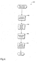
- FIGURE 4 is a flow chart of the steps performed in invoking the expert system 308.
- the application 306 calculates a set of parameters that will be passed to the expert system 308.
- the term "calculate” means the inclusion of the parameters predefined by the user interface designer or parameters that are collected, analyzed, or adapted for a purpose by the application 306.
- the application 306 reflects the programmer's intent by invoking the relevant expert system code module and passing in the relevant parameters.
- the expert system 308 generates and returns a representation of an appropriate user interface 310.
- the application 306 invokes this generated user interface 310.
- the application 306 is not aware of what form the generated user interface 310 will take. The application 306 only knows that it can expect to be notified when the user interface has finished processing, and what the result of the interaction was. Processing continues to step 408, where the application 306 can perform any necessary operations using the result of the interaction with the user.
- the expert system 308 can offer the application 306 an option to have the expert system 308 itself invoke the generated user interface 310 directly. In this case, instead of returning the generated user interface 310, the expert system 308 returns the result of the interaction with the user. From the perspective of the application 306, such an option effectively combines steps 404 and 406 into a single step.
- FIGURE 5 illustrates a process 500 where the expert system 308 has received an intention or a user interface goal 324 from the application 306.
- the expert system 308 receives the user interface goal 324 via a suitable mechanism, such as a function invocation.
- the expert system 308 receives a set of parameters associated with the function invocation at a block 504.
- the expert system 308 selects a code module among multiple code modules 334-338, which corresponds with the received user interface goal among multiple user interface goals.
- the process 500 flows next to a block 508 where the expert systems 308 selects a rule from a set of rules within the selected code module.
- the set of rules are programmatically defined in the selected code module.
- Each code module 334-338 includes different rules extracted from guidelines, conventions, and principles of user interface design. An example of these extracted rules are discussed below with reference to FIGURE 6.
- the process 500 enters a block 510.
- the expert system 308 generates a user interface from a template associated with a selected rule. Each rule within a module corresponds to a different template.
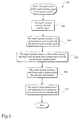
- FIGURE 6 depicts a set of rules within an implementation of the code module or component 334 designed to address the general goal of having the user select a single item from a list of choices.
- the expert system 308 generates a graphical user interface for use on the Microsoft Windows operating system, following the guidelines set forth by Microsoft to determine which type of control is most appropriate for the task.
- the expert system 308 in this case requires the application 306 to supply a list of choices 326A when the code module is invoked.
- the programmer can optionally supply constraints limiting the size of any screens generated by the expert system 308 (e.g., to ensure that the screens can fit on a particular display or within a preexisting window).
- the expert system 308 determines which sort of user interface will be most appropriate in satisfying the programmer's goal.
- step 602 the expert system 308 counts the number of choices that will be offered to the user.
- step 604 the expert system 308 determines whether the count of choices is zero. If it is zero, the user will have no choice to make. In this case, processing continues to step 606, where the expert system 308 generates a user interface 310 containing no visible screens. Upon later invocation, this user interface 310 will immediately return to the application 306, passing back a result that indicates no selection was made by the user.
- step 608 determines if the count of choices is exactly one. If so, processing continues to step 610, where the expert system generates a user interface 310 again containing no visible screens. Upon later invocation, this user interface 310 will immediately return to the application 306, passing back a result that indicates the user selected the only available choice.
- step 612 the expert system 308 determines that if the count is less than eight (i.e., greater than or equal or two and also less than or equal to seven). If so, processing continues to step 614, where the expert system 308 generates a user interface 310. Upon later invocation, this user interface 310 will display a single screen showing the available choices using option buttons. An example of such a screen is shown in FIGURE 7.
- step 616 the expert system 308 considers whether there are any constraints on the amount of vertical space available to the generated user interface, and if so, whether there is sufficient vertical space to display a single-selection list box displaying at least three items. If there is sufficient room, processing continues to step 618, where the expert system 308 generates a user interface 310. Upon later invocation, this user interface 310 will display a single screen showing the available choices in a single-selection list box. An example of such a screen is shown in FIGURE 8.
- step 620 the expert system 308 generates a user interface 310.
- this user interface 310 displays a single screen showing the available choices in a drop-down list box. An example of such a screen is shown in FIGURE 9B.
- FIGURE 7 is an example of a graphical user interface screen generated by the expert system 308 in which the user is asked to choose one of four items.
- a window 702 contains text 704 instructing the user to make a selection from the option buttons 706, 708, 710, and 712.
- option button 706 is shown selected. Only one of the option buttons 706, 708, 710, and 712 can be selected at a given time.
- the user selects one of the buttons, then clicks an OK button 714 to indicate that he is finished.
- the window is closed, and the user interface returns the user's selection to the application 306. If the user pressed the OK button 714 in the screen state shown, this first option would be returned to the application 306.
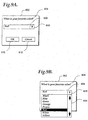
- FIGURE 8 is an example of a graphical user interface screen generated by the expert system 308, in which the user is asked to choose one of ten items.
- a single window 802 contains text 804 instructing the user to make a selection from a single-selection list box 806 containing ten items (not all ten are shown).
- the list box 806 is only tall enough to show eight items. The user must scroll the list box 806 to see all the items. The user selects one of the list items, then clicks an OK button 808 to indicate that he is finished.
- the window is closed, and the user interface returns the user's selection to the application 306. If instead the user clicks a Cancel button 810, the window is closed, and the application 306 is informed that the user did not make a selection.
- FIGURES 9A-9B depict another example of a screen in a graphical user interface generated by the expert system 308, in which the user is again asked to choose one often items. (Not all ten are shown)
- the programmer has established some constraints on the size of the output display the user interface can employ.
- the window 902, shown in FIGURE 9A contains text 904 instructing the user to make a selection.
- the expert system 308 has instead chosen a more compact representation of the choices, a drop-down list box 906.
- the drop-down list box 906 is initially collapsed to a single line.
- the user can expand it to reveal a list box 914.
- This list box 914 displays a portion of the available choices. The user must scroll the list to see the remainder. The user selects one of the items in the list box 914, and then clicks drop-down arrow 908 once more to uncollapse the list to its initial state. The user then clicks an OK button 910 to indicate that he is finished. The window closes, and the user interface returns the user's selection to the application 306. If the user clicks a Cancel button 612, the window 902 is closed instead, and the application 306 is informed that the user did not make a selection.
- the expert system 308 is a separable component from the program created by the programmer, and may be separately updated or otherwise modified. Accordingly, multiple programs on the same machine may invoke the same instance of the expert system 308. As the expert system 308 is improved or modified with additional user interface knowledge in subsequent versions, the expert system 308 may make different decisions. Different versions of the expert system 308 may generate different user interfaces given the same intention or user interface goal, set of parameters, and external factors.
- the expert system 308 may invoke itself recursively to construct a portion of the user interface.
- a code module capable of generating a complex graphical user interface with multiple screens may invoke other code modules to generate the individual screens.
- a programmer may be content to take advantage of the expert system's 308 existing knowledge of user interface design principles.
- the programmer may also have the ability to codify new knowledge of user interface design principles (perhaps in some specific domain) by creating new code modules and adding them to the expert system 308 itself. This makes the knowledge available to other programmers as well.
Abstract
Description
- This application claims the benefit of U.S. Provisional Application No. 60/272,006, filed February 27, 2001, which is expressly incorporated herein by reference.
- The present invention relates generally to expert systems and, more particularly, to an a piece of software that receives intentions of a user interface designer from an application and realizes the intentions by making decisions to generate user interfaces from a set of programmatic rules, which are based on knowledge of experts in the field of user interfaces as embodied in guidelines, conventions, and principles of user interface design.
- A user interface is a portion of a program or an operating system through which a user can instruct a computing device to accomplish a result and through which the device can convey information to the user. Examples of computing devices are computers, portable electronic devices such as telephones, and interactive television units. (Hereafter, the term computer is used to refer generally to all computing devices.)
- A graphical user interface is a user interface that makes use of a computer monitor or other type of display (such as a television) as an output device, and one or more input devices, typically a computer keyboard and a pointing device, such as a mouse, that affect the display. The computer displays information to the user in screens. A screen may take up the entire viewable area of the display, or may take up only a portion of the viewable area in the form of a window. Another example of a user interface is an audio user interface in which the user speaks to the computer through a microphone input device, and the computer responds via a speaker output device. Some user interfaces support multiple modes of interaction (e.g., graphical and audio).
- Software programmers create user interfaces with programming languages that allow access to a computer's input and output devices. However, these user interfaces need not be created from scratch. For example, with reference to FIGURE 1A, a collection of user interface routines may be stored in a library (not shown) resident in an operating system, such as the Microsoft Windows operating system 118 (hereafter, "Windows 118"). To invoke a user interface routine in the library, software programmers place a function call, which invokes a corresponding routine in the library, at an appropriate place in a
program 116. When the computer that is running theprogram 116 comes to the function call, the computer executes the function call and transforms the function call into a request for service from the corresponding user interface routine in the library. - Each function call includes a set of input arguments. The input arguments are passed along to the corresponding user interface routine when the function call is executed by the computer. Each routine is designed to present a user interface from a particular template, such as a
dialog box 120, which is a special window that solicits a response from a user. The input arguments provide information that may affect the presentation of thedialog box 120. Each function call has a one-to-one correspondence with a single template in one routine. There is an expectation that for each function call a precise instance of a particular template will appear. There can be no deviation since any deviation is considered a bug in Windows 118. - FIGURES 1B-1E illustrate message boxes 124-130, which are a type of the
dialog box 120. The template from which each message box is formed includes atitle bar 102, which is a horizontal space at the top of the message box that contains the name of the message box, and aclose button 104, which is a square button that is usually located in the right comer of the title bar with an x mark on it. The template for the message box also includes ascreen 106 for containing messages as well as one or more buttons to allow the user to interact with the message box. - The
message box 124 in FIGURE 1B presents a message "Hello world!" to a user along with anOK button 108. The function call to create the FIGURE 1Bmessage box 124 may be of a form: messageBox("Hello World!", OK), which is a function call having a name "messageBox" and two input arguments "Hello World!" and "OK." The FIGURE1C message box 126 is similar to the FIGURE 1Bmessage box 124, except that the FIGURE1C message box 126 also includes aCancel button 110. The function call to create the FIGURE1C message box 126 may have a form: messageBox("Hello World!", OK_CANCEL). The FIGURE1D message box 128, like the FIGURES 1B-1C message boxes 1D message box 128 includes aYES button 114, aNO button 112, as well as the Cancelbutton 110, but noOK button 108. The function call to create themessage box 128 may have the form: messageBox("Hello World!", YES_NO_CANCEL). - The input arguments to the function call that creates the FIGURE
1E message box 130 includes a long string of text "Call me Ishmael..." and theOK button 108. The user interface routine that corresponds to the function call that creates the FIGURE1E message box 130 increases the vertical space of the FIGURE1E message box 130 so as to accommodate the long string of text. A form of the function call to create the FIGURE1E message box 130 include a signature, such as messageBox("Call me Ishmael...", OK). FIGURES 1B-1E illustrate that a the function call messageBox(...) is made from theprogram 116, a messageBox template in Windows 118 is used to create message boxes 124-130. Modifications to a message box template can be made by furnishing certain information through the input arguments to the function call messageBox(...), but a modified message box is still a kind of a message box, and no deviation will be made by Windows 118. - User interfaces can be constructed directly in the programming languages used by software programmers as discussed above with reference to FIGURES 1A-1E, but are more often constructed using specialized user interface development tools. For example, graphical user interfaces are often constructed using a tool called a forms package. A forms package typically presents the programmer with a screen (also called a form) that approximates what the user will see. The forms package allows the programmer to add individual graphical user interface controls (e.g., buttons, text entry boxes, list boxes) to the screen, and arrange the controls on the screen. The forms package also allows the programmer to indicate how the screen and its controls should react to user actions, such as when the user clicks on a button control with a mouse. Typically, the programmer defines these reactions explicitly by writing routines in computer code, and then connecting controls on the screen to those routines. Specific user events then trigger the execution of the associated code routines.
- A graphical user interface for a program may consist of one or many screens. Forms packages allow the programmer complete freedom in constructing user interfaces with whatever screens the programmer desires. However, with this freedom comes the opportunity to make many mistakes. The programmer may create a user interface that is too complex for its users to understand and use properly. The programmer may inadvertently create a user interface with bugs. An example of a bug is failing to handle correctly the entire range of possible input conditions.
- To reduce the likelihood of problems, programmers typically have learned to manually follow user interface guidelines and de facto conventions that suggest how user interfaces should appear and behave. For example, FIGURE 7 shows a type of screen in a graphical user interface, in which the user is asked to choose one of four items. A
window 702 containstext 704 instructing the user to make a selection from theoption buttons option button 706 is shown selected. Only one of theoption buttons OK button 714 to indicate that he is finished. The user can also click a Cancelbutton 716 to indicate that he does not wish to make a selection. - As an example of the conventions at work in this screen, consider the standard placement of the
OK button 714 and the Cancelbutton 716 beneath theoption buttons buttons buttons OK button 714 or the Cancelbutton 716 before selecting an option. - The controls on the screen shown in FIGURE 7 form a familiar pattern. Many programmers create screens that follow the pattern shown in FIGURE 7 even if the specific purpose of the screen is different. In time, users of graphical user interfaces may become familiar with such patterns, thereby increasing their efficiency with a program. They may be able to more quickly learn new screens if the screens conform to patterns they have seen previously.
- Most software programming environments do not offer any way to take advantage of such user interface patterns. If the programmer wishes to employ in his program a choice selection screen that follows the same pattern as the one shown in FIGURE 7, he typically must use a forms package to create such a screen from scratch using basic graphical user interface controls. Because the programmer generally defines the appearance and behavior of the screen from scratch, he may implement the user interface incorrectly, thereby inadvertently introducing bugs. This may occur even when the programmer is trying to create a screen that follows a familiar pattern.
- Even for simple user interface patterns, it may be difficult for the programmer to correctly follow the pattern. The programmer needs to get a number of details correct in order for users to gain any advantage from the use of the pattern. Examples of such details include, but are not limited to, choosing the correct set of controls, providing conventional or otherwise meaningful labels for these controls, arranging the controls correctly on the screen, supporting all available modes of user input (keyboard, pointing device, voice recognition, etc.), correctly handling all conditions and errors, enabling the interface to be used correctly in a variety of locales and languages, and enabling the interface to be used correctly by people with a variety of physical disabilities (color blindness, nearsightedness, blindness, slow physical coordination, etc.).
- Moreover, the guidelines for determining which type of user interface pattern is appropriate in a given situation are not trivial. Consider a situation in which a programmer wishes to present the user with a series of choices and require the user to select exactly one of the choices. Suppose the programmer is creating a graphical user interface for use on the Microsoft Windows operating system. Microsoft Corporation publishes a set of user interface guidelines for programs designed for Windows ("Microsoft Windows User Experience: Official Guidelines for User Interface Developers and Designers", Microsoft Press, 1999). These guidelines suggest at least three different types of controls that could be employed in this situation:
- 1) Option buttons: "An option button, also referred to as a radio button, represents a single choice within a limited set of mutually exclusive choices. That is, the user can choose only one of a set of options. Accordingly, always group option buttons in sets of two or more.... Limit the use of option buttons to small sets of options, typically seven or less, but always at least two. If you need more choices, consider using a different type of control, such as a single selection list box or drop-down list box." (p. 164)
- 2) Single-selection list boxes: "A list box is a control for displaying a list of choices for the user.... List boxes are best for displaying large numbers of choices that vary in number or content.... A single-selection list box is designed for the selection of only one item in a list. Therefore, the control provides a mutually exclusive operation similar to a group of option buttons, except that a list box can handle a large number of items more efficiently. Define a single-selection list box to be tall enough to show at least three to eight choices... depending on the design constraints of where the list box is to be used." (pp. 170-4)
- 3) Dropdown list boxes: "Like a single-selection list box, a drop-down list box provides for the selection of only a single item from a list; the difference is that the list is displayed upon demand. .... While drop-down list boxes are an effective way to conserve space and reduce clutter, they require more user effort to browse and select an item than a single-selection list box." (p. 175)
-
- Portentously, the decision as to which control should be used is left to the programmer. The programmer must evaluate the situation at hand, compare it to the available guidelines and conventions, and then make an appropriate selection. Failure to select the appropriate pattern may risk confusing users.
- Complicating the programmer's decision is that, at the time the programmer is writing the program, the programmer is typically unable to know the exact conditions under which the user interface will be used. A program may need to offer the user a list of choices where the number of choices varies greatly depending upon factors that change (e.g., the program needs to display a list of people currently connected to a computer network). The programmer is often forced to make decisions based on a theoretical or estimated range of values for such a factor. The decision made at the time of writing the program may result in a user interface that is inappropriate in practice.
- The present invention moves much of the burden of identifying and constructing an appropriate user interface pattern to an expert system, which is programmed to follow guidelines, conventions, and principles of user interface design. A programmer writes an application in a traditional manner, but does not need to create a complete user interface for the application. Instead, the programmer writes code to reflect his intentions for the purpose of the user interface and these pieces of code invoke the expert system, which completes the user interface of the application. The expert system generates an appropriate user interface on the fly and returns this interface to the application. The application then invokes this user interface, which controls user interaction. The user interface communicates with the application as necessary. The user interface eventually returns control to the application when the user interface receives some indication from the user's interaction. Instead of generating the user interface on the fly, alternatively, the expert system generates and stores the user interface for later use during runtime of the application. The programmer can use the expert system to generate an application's entire user interface or just a portion of it.
- The foregoing aspects and many of the attendant advantages of this invention will become more readily appreciated as the same become better understood by reference to the following detailed description, when taken in conjunction with the accompanying drawings, wherein:
- FIGURE 1A is a block diagram illustrating a one-to-one correspondence between a user interface function call in a program, a specific user interface routine in an operating system, and a corresponding presentation of a user interface from a specific template.
- FIGURES 1B-1E are a pictorial diagram illustrating various presentations of a message box, which depend on the values of the input arguments to a user interface function call.
- FIGURE 2 is a block diagram illustrating a computing device.
- FIGURE 3A is a block diagram illustrating a computing system that contains an expert system for generating user interfaces according to one embodiment of the invention.
- FIGURE 3B is a block diagram illustrating in greater detail the intentions of the user interface designer and parameters to an expert system for generating user interfaces according to one embodiment of the invention.
- FIGURE 3C is a block diagram showing in greater detail the interaction between an application, which sends one or more intentions of a user interface designer to an expert system, and an expert system receiving the one or more intentions from the application so as to generate user interfaces according to one embodiment of the invention.
- FIGURE 4 is a process diagram illustrating a method for invoking an expert system according to one embodiment of the invention.
- FIGURE 5 is another process diagram illustrating a method by which an expert system realizes an intention of the user interface designer to generate a user interface according to one embodiment of the invention.
- FIGURE 6 is a process diagram showing a method inside a sample code module or component of an expert system for realizing an intention of a user interface designer, and more particularly, for showing to a user the available choices according to one embodiment of the invention.
- FIGURE 7 is a pictorial block diagram illustrating choices available to a user to select using option buttons according to one embodiment of the invention.
- FIGURE 8 is a pictorial block diagram illustrating a screen showing the choices available to a user in a single-selection list box according to one embodiment of the invention.
- FIGURE 9A is a pictorial block diagram of a single screen showing the selected choice of a drop-down list box according to one embodiment of the invention.
- FIGURE 9B is a pictorial block diagram illustrating a single screen showing the choices available to a user in a drop-down list box according to one embodiment of the invention.
-
- FIGURE 2 illustrates an example of a suitable
computing system environment 200 on which the invention may be implemented. Thecomputing system environment 200 is only one example of a suitable computing environment and is not intended to suggest any limitation as to the scope of use or functionality of the invention. Neither should thecomputing environment 200 be interpreted as having any dependency or requirement relating to any one or combination of the illustrated and described components. - The invention is operational with numerous other general purpose or special purpose computing system environments or configurations. Examples of well-known computing systems, environments and/or configurations that may be suitable for use with the invention include, but are not limited to, personal computers, server computers, handheld or laptop devices, multiprocessor systems, microprocessor-based systems, set top boxes, programmable consumer electronics, network PCs, minicomputers, mainframe computers, distributed computing environments that include any of the above systems or devices, and the like.
- The invention is described in the general context of computer-executable instructions, such as program modules being executed by a computer. Generally, program modules include routines, programs, objects, components, data structures, etc., that perform particular tasks or implement particular abstract data types.
- The invention may also be practiced in distributed computing environments where tasks are performed by remote processing devices that are linked through a communications network. In a distributed computing environment, program modules may be located in both local and remote computer storage media, including memory storage devices.
- With reference to FIGURE 2, a system for implementing the invention includes a general purpose computing device in the form of a
computer 210. Components ofcomputer 210 may include, but are not limited to, aprocessing unit 220, asystem memory 230, and asystem bus 221 that couples various system components including the system memory to theprocessing unit 220. Thesystem bus 221 may be any of several types of bus structures, including a memory bus or memory controller, a peripheral bus, and a local bus using any of a variety of bus architectures. By way of example, and not limitation, such bus architectures include Industry Standard Architecture (ISA) bus, Micro Channel Architecture (MCA) bus, Enhanced ISA (EISA) bus, Video Electronics Standards Association (VESA) local bus, and Peripheral Component Interconnect (PCI) bus, also known as Mezzanine bus. -
Computer 210 typically includes a variety of computer readable media. Computer readable media can be any available media that can be accessed bycomputer 210 and includes both volatile and nonvolatile media, removable and non-removable media. By way of example, and not limitation, computer readable media may comprise computer storage media and communication media. Computer storage media includes both volatile and nonvolatile, removable and non-removable media implemented in any method or technology for storage of information such as computer readable instructions, data structures, program modules or other data. Computer storage media includes, but is not limited to, RAM, ROM, EEPROM, flash memory or other memory technology, CD-ROM, digital versatile disks (DVD) or other optical disk storage, magnetic cassettes, magnetic tapes, magnetic disk storage or other magnetic storage devices, or any other computer storage media. Communication media typically embodies computer readable instructions, data structures, program modules or other data in a modulated data signal, such as a carrier wave or other transport mechanism that includes any information delivery media. The term "modulated data signal" means a signal that has one or more of its characteristics set or changed in such a manner as to encode information in the signal. By way of example, and not limitation, communication media includes wired media, such as a wired network or direct-wired connection, and wireless media such as acoustic, RF infrared, and other wireless media. A combination of any of the above should also be included within the scope of computer readable media. - The
system memory 230 includes computer storage media in the form of volatile and/or nonvolatile memory such as read-only memory (ROM) 231 and random access memory (RAM) 232. A basic input/output system 233 (BIOS), containing the basic routines that help to transfer information between elements withincomputer 210, such as during startup, is typically stored inROM 231.RAM 232 typically contains data and/or program modules that are immediately accessible, and/or presently being operated on, by processingunit 220. By way of example, and not limitation, FIGURE 2 illustratesoperating system 234,application programs 235,other program modules 236, andprogram data 237. - The
computer 210 may also include other removable/non-removable, volatile/nonvolatile computer storage media. By way of example only, FIGURE 2 illustrates thehard disk drive 241 that reads from or writes to non-removable, nonvolatile magnetic media, themagnetic disk drive 251 that reads from or writes to a removable, nonvolatilemagnetic disk 252, and anoptical disk drive 255 that reads from or writes to a removable, nonvolatileoptical disk 256, such as a CD-ROM or other optical media. Other removable/non-removable, volatile/nonvolatile computer storage media that can be used in the exemplary operating environment include, but are not limited to, magnetic tape cassettes, flash memory cards, digital versatile disks, digital videotapes, solid state RAM, solid state ROM, and the like. Thehard disk drive 241 is typically connected to thesystem bus 221 through a non-removable memory interface, such asinterface 240, and themagnetic disk write 251 andoptical disk drive 255 are typically connected to thesystem bus 221 by a removable memory interface, such asinterface 250. - The drives and their associated computer storage media discussed above and illustrated in FIGURE 2 provide storage of computer readable instructions, data structures, program modules, and other data for the
computer 210. In FIGURE 2, for example,hard disk drive 241 is illustrated as storingoperating system 244,application programs 245,other program modules 246, andprogram data 247. Note that these components can either be the same as or different fromoperating system 234,application programs 235,other program modules 236, andprogram data 237.Operating system 244,application programs 245,other program modules 246, andprogram data 247 are given different numbers here to illustrate that, at a minimum, they are different copies. A user may enter commands and information into thecomputer 210 through input devices, such as akeyboard 262 andpointing device 261, commonly referred to as a mouse, trackball, or touch pad. Other input devices (not shown) may include a microphone, joystick, game pad, satellite dish, scanner, or the like. These and other input devices are often connected to theprocessing unit 220 through auser input interface 260 that is coupled to the system bus, but may be connected by other interface and bus structures, such as a parallel port, game port, or universal serial bus (USB). Amonitor 291 or other type of display device is also connected to thesystem bus 221 via an interface, such as avideo interface 290. In addition to the monitor, computers may also include other peripheral output devices, such asspeakers 297 andprinter 296, which may be connected through an input/outputperipheral interface 295. - The
computer 210 may operate in a networked environment using logical connections to one or more remote computers, such as aremote computer 280. Theremote computer 280 may be a personal computer, a server, a router, a network PC, a peer device, or other common network node, and typically includes many or all of the elements described above relative to thecomputer 210, although only amemory storage device 281 has been illustrated in FIGURE 2. The logical connections depicted in FIGURE 2 include a local area network (LAN) 271 and a wide area network (WAN) 273, but may also include other networks. Such network environments are commonplace in offices, enterprise-wide computer networks, intranets, and the Internet. - When used in a LAN networking environment, the
computer 210 is connected to theLAN 271 through a network interface oradapter 270. When used in a WAN networking environment, thecomputer 210 typically includes amodem 272 or other means for establishing communications over theWAN 273, such as the Internet. Themodem 272, which may be internal or external, may be connected to thesystem bus 221 via the input/outputperipheral interface 295, or other appropriate mechanism. In a networked environment, program modules depicted relative to thecomputer 210, or portions thereof, may be stored in the remote memory storage device. By way of example, and not limitation, FIGURE 2 illustratesremote application programs 285 as residing onmemory device 281. It will be appreciated that the network connections shown are for illustrative purposes only and other means of establishing a communications link between the computers may be used. - FIGURE 3A depicts a
computer 302 suitable for practicing the preferred embodiment of the present invention. An area ofmemory 304 contains anapplication 306 written by the programmer. Thisapplication 306 invokes anexpert system 308. Theexpert system 308 considers information passed to it from theapplication 306 and possibly also examines external factors stored on apermanent storage device 312 or on anothercomputer 320 connected via anetwork 318. Theexpert system 308 generates auser interface 310 and returns theuser interface 310 to theapplication 306. Theapplication 306 invokes theuser interface 310 to interact with the user right after theuser interface 310 is created or at runtime if the generateduser interface 310 has been stored away. Theuser interface 310 controls this interaction by communicating information to the user via anoutput device 314 and receiving input from the user via aninput device 316. When the interaction is complete, theuser interface 310 returns any result of the interaction to thecalling program 306. - The programmer or a user interface designer begins the process of generating the
user interface 310 by indicating the user interface goal or his intention to theexpert system 308. FIGURE 3B illustrates in greater detail the communication of a user interface goal or an intention (hereafter, user interface goal(s) 324 or intention(s) 324) to theexpert system 308.Intentions 324 are stored in theapplication 306. Theapplication 306 may have an incomplete user interface. Whenintentions 324 are communicated to theexpert system 308 to generate theuser interface 310, the incomplete user interface of theapplication 306 is completed. Many suitable techniques to implementintentions 324 can be used. One suitable technique includes storingintentions 324 on theapplication 306 as function calls. Each function call has a set ofparameters 326 associated with it. Various kinds of user interface goals or intentions are possible, such as what sort of question to ask the user, what sort of information to communicate to the user, or what sort of task to have the user perform. Examples of such user interface goals or intentions include the following: - 1) Have the user supply a single string of text.
- 2) Have the user supply a single number (e.g., an integer greater than zero).
- 3) Have the user pick a single item from a list.
- 4) Have the user pick several items from a list.
- 5) Have the user arrange the items in a list into a preferred order.
- 6) Have the user manage a list of items (add items, edit them, remove them).
- 7) Have the user organize items in a given structure (e.g., a hierarchy).
- 8) Have the user move or copy items between two containers (e.g., files between two folders).
- 9) Have the user apply one or more operations on a selection of items in a list.
-
- In addition to indicating a user interface goal or an
intention 324, the programmer can supplyparameters 326 to theexpert system 308 that further specify the programmer's intent, or otherwise assist theexpert system 308 in generating a meaningful user interface. Theexpert system 308 may also require the programmer to supply someparameters 326 depending on the specified user interface goal or intention. Other parameters may be optional. Examples ofparameters 326 include: - 1) The text of the question or instructions the programmer would like to offer the user
- 2) The choices from which the user is expected to make a selection (for example, a list of text strings)
- 3) The data the programmer wishes to allow the user to manipulate
- 4) The default response to a question
- 5) An indication of whether the user is required to respond to a question or whether the user can opt out of the question
- 6) The type of data the programmer expects to be received in response to the interaction with the user (both for validity checking and to determine the type of display that would be most effective)
- 7) Constraints on the amount of horizontal and vertical space the programmer may wish to impose on the generated user interface
- 8) Indications of the visual style the programmer would prefer in the generated user interface (for example, whether the expert system should generate a user interface with a conservative visual style that allows the user to focus on the task at hand, or a user interface with a visually engaging style that is meant to entertain).
-
- The
expert system 308 may also examine external factors available to it in making a decision about which user interface is most appropriate. These external factors might include: - 1) What type of computer is the program running on? For example, the speed of the device's central processor may place limits on the amount of processing acceptable for the user interface to perform.
- 2) What operating system is the program running on? While many modern operating systems provide similar user interfaces, each operating system may define its own conventions for how certain kinds of interactions should be conducted.
- 3) What types of input devices are available? Most personal computers will have at least a computer keyboard, and will also have a pointing device such as a mouse. Other devices may have touch screens, microphones for voice input, and other input devices. For example, a telephone will have a numeric keypad.
- 4) What types of output devices are available? Most devices will have a screen, in which case various screen attributes may be relevant: its physical size, its resolution (the number of pixels it can display), and how many colors it can display. Another example of an output device is an audio speaker.
- 5) Who is the typical user to whom these questions will be asked? Relevant factors might include expectations of the typical user's age, nationality and cultural background, the languages spoken or read, degree of general computer experience, physical abilities, and the physical environment in which the user will use the product.
- 6) What is known about the specific individual to whom the present question is being asked? The expert system may include specific answers to the above general user attributes for a previously identified individual.
- 7) What is the history of the specific user's experience with this question or similar questions in the past? For example, if the user has never faced this question before, he may require a user interface that provides more explicit assistance. If, on the other hand, the user has faced this question many times before, and always provided the same response, the expert system may offer the user's usual response as a default - or the expert system may generate a user interface that displays nothing to the user and immediately returns the default response.
- 8) What other software is available on the machine? The expert system may decide to employ other software applications in forming the user interface it will use to ask a question.
- 9) What are the current values of various data the expert system has access to? The expert system may choose a user interface based on various facts about the world that it can perceive through the machine, such as the time of day. Additionally, if the machine has access to a network of other devices (such as the Internet), the expert system may be able to use data from the network to inform its selection and design of a user interface.
-
- Importantly, the user interface generated by the
expert system 308 for an intention may be radically different under different input conditions - or even under identical input conditions (because external factors may have changed). That is, theexpert system 308 may offer the programmer no guarantee it will generate the same user interface if invoked multiple times with the same intention and the same set ofparameters 326. - If the
expert system 308 is generating a graphical user interface, the generateduser interface 310 may include a single screen, a sequence of multiple screens, or include no screens at all. Here, "screen" is used generally to refer to either the entire visible display area on an output device, or a window contained within a larger display, or a portion of a window. The generated user interface can include screens encapsulated in pagefunctions, which are described in U.S. Application No. , filed February 27, 2002, titled "PAGEFUNCTION ARCHITECTURAL SOFTWARE FRAMEWORK," and which is incorporated herein by reference (Attorney Docket No. MSFT-1-18569). For generated user interfaces that do include screens, the controls on the screens may vary from invocation to invocation, as may the controls' attributes: their labels, positions, sizes, contained values, etc. Theexpert system 308 may also generate other types of user interfaces other than graphical user interfaces (e.g., audio user interfaces). - With reference to FIGURE 3C, the
expert system 308 is implemented as a collection of code modules or components 334-338. Each code module is designed to generate appropriate user interfaces for a single type of user interface goal or intention. In other words, each code module has access to different kinds of templates to realize the user interface goal or intention. The programmer indicates his user interface goal or intention by writing programming code for theapplication 306 that invokes the relevant code module. In order to be invoked properly, a code module may require theapplication 306 to supply certain parameters. Upon invocation, a code module may also allow theapplication 306 to specify additional optional parameters. These required and optional parameters may differ from intention to intention (and, hence, from code module to code module). A code module evaluates the required and optional parameters, and examines any relevant external factors, to determine which sort of user interface is appropriate. - As shown in FIGURE 3C, the
application 306 includes pieces of written code for representing various intentions of the programmer, such as an intention for ordering a list ofitems 332, an intention for choosing an item from alist 330, andother intentions 340. Each intention stored on theapplication 306 can invoke, on theexpert system 308, a corresponding code module or component, such asOrder component 336, Choosecomponent 334, andother components 338. The Choosecomponent 334 corresponds to the intention for helping a user to choose an item from alist 330. In order for the intention for helping a user to choose an item from alist 330 to correctly invoke the Choosecomponent 334, the intention is written in a particular programmatic form, such as a function call Choose(...) 324A. The parameters for thefunction call 324A may include a list ofitems 326A from which a user is to choose. Similarly, theOrder component 336 corresponds to the intention for ordering a list ofitems 332. The intention for ordering a list ofitems 332 invokes theOrder component 336 via the function call Order(...) 324A. A list ofitems 326B make up the parameters for thefunction call 324B.Other intentions 340 on theapplication 306 havecorresponding components 338 in theexpert system 308. The appropriate component among thecomponents 338 are invoked by a proper function call along with an appropriate set of parameters that should be included in the function call. - Once the expert system code module has determined what sort of user interface is appropriate, the module generates a suitable representation of the
user interface 310 and returns the representation to theapplication 306. Suitable operating environments for various embodiments of the present invention include an object-oriented environment. Theuser interface 310 can be represented as an object that is dynamically created during program execution, passed between program functions, have its member functions invoked, and have these member functions return results to the invoking program. Such an object will interact with the machine's input and output devices to carry out the requested interaction with the user. One skilled in the art will recognize that embodiments of the present invention can be practiced in a non-object-oriented environment as well. - After the
expert system 308 generates theuser interface 310 and returns it to theapplication 306, thecalling program 306 will typically invoke the generateduser interface 310 immediately. However, it is also possible for theapplication 306 to store a representation of theuser interface 310 on storage media (e.g., a disk) for later use by the application 306 (or, potentially, a different program). The representation of theuser interface 310 could also be transmitted to another computer for storage or invocation by a program on that computer. Note, however, that the more time that elapses between the time the user interface is generated and the time it used, the more likely it is that various external factors will have changed from their values at the time they were examined by theexpert system 308 thereby, potentially causing the user interface to be inappropriate under the new set of external factors. - Although FIGURE 3A depicts the
application 306, theexpert system 308, and the generateduser interface 310 as all residing on thesame computer 302, one skilled in the art will recognize that these components could exist on separate computers communicating over a network. For example, theexpert system 308 could take the form of a process on an Internet server (not shown) that returns a user interface in the form of a complete or partial HTML (Hypertext Markup Language) page suitable for display in a World Wide Web browser. - FIGURE 4 is a flow chart of the steps performed in invoking the
expert system 308. Instep 402, theapplication 306 calculates a set of parameters that will be passed to theexpert system 308. The term "calculate" means the inclusion of the parameters predefined by the user interface designer or parameters that are collected, analyzed, or adapted for a purpose by theapplication 306. Instep 404, theapplication 306 reflects the programmer's intent by invoking the relevant expert system code module and passing in the relevant parameters. Theexpert system 308 generates and returns a representation of anappropriate user interface 310. Instep 406, theapplication 306 invokes this generateduser interface 310. Theapplication 306 is not aware of what form the generateduser interface 310 will take. Theapplication 306 only knows that it can expect to be notified when the user interface has finished processing, and what the result of the interaction was. Processing continues to step 408, where theapplication 306 can perform any necessary operations using the result of the interaction with the user. - It is possible for the
expert system 308 to offer theapplication 306 an option to have theexpert system 308 itself invoke the generateduser interface 310 directly. In this case, instead of returning the generateduser interface 310, theexpert system 308 returns the result of the interaction with the user. From the perspective of theapplication 306, such an option effectively combinessteps - FIGURE 5 illustrates a
process 500 where theexpert system 308 has received an intention or auser interface goal 324 from theapplication 306. At ablock 502, theexpert system 308 receives theuser interface goal 324 via a suitable mechanism, such as a function invocation. Along with the function invocation, theexpert system 308 receives a set of parameters associated with the function invocation at ablock 504. - Next, at a
block 506, theexpert system 308 selects a code module among multiple code modules 334-338, which corresponds with the received user interface goal among multiple user interface goals. Theprocess 500 flows next to ablock 508 where theexpert systems 308 selects a rule from a set of rules within the selected code module. The set of rules are programmatically defined in the selected code module. Each code module 334-338 includes different rules extracted from guidelines, conventions, and principles of user interface design. An example of these extracted rules are discussed below with reference to FIGURE 6. After a rule is selected, theprocess 500 enters ablock 510. Here, having selected and executed the selected rule, theexpert system 308 generates a user interface from a template associated with a selected rule. Each rule within a module corresponds to a different template. - FIGURE 6 depicts a set of rules within an implementation of the code module or
component 334 designed to address the general goal of having the user select a single item from a list of choices. In this example, theexpert system 308 generates a graphical user interface for use on the Microsoft Windows operating system, following the guidelines set forth by Microsoft to determine which type of control is most appropriate for the task. Theexpert system 308 in this case requires theapplication 306 to supply a list ofchoices 326A when the code module is invoked. The programmer can optionally supply constraints limiting the size of any screens generated by the expert system 308 (e.g., to ensure that the screens can fit on a particular display or within a preexisting window). Theexpert system 308 then determines which sort of user interface will be most appropriate in satisfying the programmer's goal. - In
step 602, theexpert system 308 counts the number of choices that will be offered to the user. Instep 604, theexpert system 308 determines whether the count of choices is zero. If it is zero, the user will have no choice to make. In this case, processing continues to step 606, where theexpert system 308 generates auser interface 310 containing no visible screens. Upon later invocation, thisuser interface 310 will immediately return to theapplication 306, passing back a result that indicates no selection was made by the user. - If the count is greater than zero, processing continues to step 608. Here the
expert system 308 determines if the count of choices is exactly one. If so, processing continues to step 610, where the expert system generates auser interface 310 again containing no visible screens. Upon later invocation, thisuser interface 310 will immediately return to theapplication 306, passing back a result that indicates the user selected the only available choice. - If the count is greater than one, processing continues to step 612. In this step, the
expert system 308 determines that if the count is less than eight (i.e., greater than or equal or two and also less than or equal to seven). If so, processing continues to step 614, where theexpert system 308 generates auser interface 310. Upon later invocation, thisuser interface 310 will display a single screen showing the available choices using option buttons. An example of such a screen is shown in FIGURE 7. - If the count is greater than or equal to eight, processing continues to step 616. In this step, the
expert system 308 considers whether there are any constraints on the amount of vertical space available to the generated user interface, and if so, whether there is sufficient vertical space to display a single-selection list box displaying at least three items. If there is sufficient room, processing continues to step 618, where theexpert system 308 generates auser interface 310. Upon later invocation, thisuser interface 310 will display a single screen showing the available choices in a single-selection list box. An example of such a screen is shown in FIGURE 8. - Otherwise (if there is not enough room for a list box), processing continues to step 620, where the
expert system 308 generates auser interface 310. Upon later invocation, thisuser interface 310 displays a single screen showing the available choices in a drop-down list box. An example of such a screen is shown in FIGURE 9B. Once processing completes, theexpert system 308 returns to theapplication 306 and passes back the generateduser interface 310. - FIGURE 7 is an example of a graphical user interface screen generated by the
expert system 308 in which the user is asked to choose one of four items. Awindow 702 containstext 704 instructing the user to make a selection from theoption buttons option button 706 is shown selected. Only one of theoption buttons OK button 714 to indicate that he is finished. The window is closed, and the user interface returns the user's selection to theapplication 306. If the user pressed theOK button 714 in the screen state shown, this first option would be returned to theapplication 306. (This option could be returned, for example, as theinteger 1, indicating the first selection, or the text string "Red", for the text of that selection.) If instead the user clicks a Cancelbutton 716, the window is closed and the calling program is informed that the user did not make a selection. (For example, by returning a special null value, such as the integer -1, that has no meaning in the set of available choices.) - FIGURE 8 is an example of a graphical user interface screen generated by the
expert system 308, in which the user is asked to choose one of ten items. Asingle window 802 containstext 804 instructing the user to make a selection from a single-selection list box 806 containing ten items (not all ten are shown). Thelist box 806 is only tall enough to show eight items. The user must scroll thelist box 806 to see all the items. The user selects one of the list items, then clicks anOK button 808 to indicate that he is finished. The window is closed, and the user interface returns the user's selection to theapplication 306. If instead the user clicks a Cancelbutton 810, the window is closed, and theapplication 306 is informed that the user did not make a selection. - FIGURES 9A-9B depict another example of a screen in a graphical user interface generated by the
expert system 308, in which the user is again asked to choose one often items. (Not all ten are shown) Here the programmer has established some constraints on the size of the output display the user interface can employ. Like the screen shown in FIGURE 8, thewindow 902, shown in FIGURE 9A, containstext 904 instructing the user to make a selection. Here, however, there is not enough vertical space to use the single-selection list box 806. In this case, theexpert system 308 has instead chosen a more compact representation of the choices, a drop-downlist box 906. The drop-downlist box 906 is initially collapsed to a single line. By clicking the drop-downarrow 908, the user can expand it to reveal alist box 914. Thislist box 914 displays a portion of the available choices. The user must scroll the list to see the remainder. The user selects one of the items in thelist box 914, and then clicks drop-downarrow 908 once more to uncollapse the list to its initial state. The user then clicks anOK button 910 to indicate that he is finished. The window closes, and the user interface returns the user's selection to theapplication 306. If the user clicks a Cancelbutton 612, thewindow 902 is closed instead, and theapplication 306 is informed that the user did not make a selection. - The
expert system 308 is a separable component from the program created by the programmer, and may be separately updated or otherwise modified. Accordingly, multiple programs on the same machine may invoke the same instance of theexpert system 308. As theexpert system 308 is improved or modified with additional user interface knowledge in subsequent versions, theexpert system 308 may make different decisions. Different versions of theexpert system 308 may generate different user interfaces given the same intention or user interface goal, set of parameters, and external factors. - In constructing complex user interfaces, the
expert system 308 may invoke itself recursively to construct a portion of the user interface. For example, a code module capable of generating a complex graphical user interface with multiple screens may invoke other code modules to generate the individual screens. - A programmer may be content to take advantage of the expert system's 308 existing knowledge of user interface design principles. The programmer may also have the ability to codify new knowledge of user interface design principles (perhaps in some specific domain) by creating new code modules and adding them to the
expert system 308 itself. This makes the knowledge available to other programmers as well. - While the preferred embodiment of the invention has been illustrated and described, it will be appreciated that within the scope of the appended claims various changes can be made therein without departing from the spirit and scope of the invention.
Claims (13)
- A system for generating user interfaces so that a user may interact with a computer system, the system comprising:an application having an incomplete user interface and being adapted to store multiple intentions of a user interface designer of the application, each intention including a set of parameters and being selected from a group consisting of posing a question to the user, presenting a piece of information to the user, and defining a task for the user to perform, the incomplete user interface of the application being completed when the one or more intentions are realized; andan expert system having one or more components for realizing the multiple intentions, the expert system receiving one of the multiple intentions and each received intention identifying and activating a corresponding component for realizing the received intention, each corresponding component programmatically containing a set of rules extracted from guidelines, conventions, and principles of user interface design, the set of parameters supplied with each received intention aiding the corresponding component to choose and execute a rule from the set of rules, each rule producing a user interface from a template different from other templates used by other rules.
- The method of Claim 1, wherein the produced user interface is selected from a group consisting of a graphical user interface, a command-line interface, and an audio user interface.
- The system of Claim 1, further comprising a source of external factors, the source of external factors containing information related to the operating environment of the application as well as the background of the user so as to aid the corresponding component to choose and execute a rule from the set of rules.
- The system of Claim 3, wherein each external factor is selected from a group consisting of the type of computer on which the application is running, the type of operating system on which the application is running, the types of available input devices, the types of available output devices, the background of the user, the existence of other software, and other facts external to the system.
- The system of Claim 1, wherein each parameter from the set of parameters is selected from a group consisting of textual information, a set of choices from which the user is expected to make a selection, pieces of data which the user is allowed to manipulate, a default response to a question posed by the user, an indication that the user is required to respond to the question, an indication that the user may opt out from responding to the question, a type of data that is expected to be received in response to an interaction with the user, a set of constraints on the dimensions of the generated user interface, and an indication of the visual style which the generated user interface may take.
- A method for generating user interfaces by an expert system for a user to interact with a computer system, comprising:receiving a user interface goal by the expert system, the user interface goal being selected from a group consisting of a question to be posed to the user, a piece of information to be communicated to the user, and a task to be performed by the user;receiving a set of parameters by the expert system, each parameter being selected from a group consisting of information for presenting to the, user, information for the task to be performed by the user, and information for constraining the generated user interface; andgenerating a user interface by selecting a code module from a set of code modules, each code module being designed to generate user interfaces from multiple templates, the act of selecting a code module including selecting a rule from a set of rules extracted from guidelines, conventions, and principles of user interface design, the act of selecting a rule being aided by the set of parameters, the user interface being produced from a template when the selected rule is executed.
- The method of Claim 6, further comprising examining selectively a set of external factors by the expert system, each factor being selected from the operating environment of the computer system and the background of the user, the act of selecting a rule being further aided by the set of external factors.
- The method of Claim 6, wherein a user interface goal is selected from a group consisting of making the user supply a single string of text, making the user supply a single number, making the user pick a single item from a list, making the user pick several items from a list, making the user arrange the items in a list in a preferred order, making the user manage a list of items, making the user organize items in a given structure, and making the user apply one or more operations on a selection of items in a list.
- The method of Claim 6, wherein the method is executed at run time while other applications are running.
- The method of Claim 6, wherein the method is executed at design time so that user interfaces generated by the method are stored on storage media.
- The method of Claim 6, wherein the generated user interface includes a pagefunction.
- A system for producing instructions suitable for making a user interface, comprising:a) an application for generating, in response to user interface designer inputs, at least one intention, said at least one intention including an associated set of parameters; andb) an expert system for receiving said at least one intention and said associated set of parameters, said expert system including a multitude of code modules, each of said code modules including a set of rules, each of said rules including a template, in response to receiving said at least one intention and said associated set of parameters said expert system:i) selecting a code module for said multitude of code modules;ii) selecting a rule from said set of rules included in said selected code module; andiii) generating user interface instructions in accordance with the template associated with said selected rule.
- A method of producing a user interface for an application running on a computer having an associated display, said method comprising:a) in response to user interface designer inputs, said application producing at least one intention, said at least one intention having an associated set of parameters;b) supplying said at least one intention and its associated set of parameters to an expert system;c) in response to receiving said at least one intention and its associated set of parameters, the expert system:i) selecting a code module from a multitude of code modules;ii) selecting a rule from a set of rules within the selected code module; andiii) generating user interface instructions from a template associated with the selected rule;d) supplying said user interface instructions to said application; ande) in response to receiving said user interface instructions, said application producing a user interface on said display.
Applications Claiming Priority (2)
| Application Number | Priority Date | Filing Date | Title |
|---|---|---|---|
| US27200601P | 2001-02-27 | 2001-02-27 | |
| US272006P | 2001-02-27 |
Publications (2)
| Publication Number | Publication Date |
|---|---|
| EP1237076A2 true EP1237076A2 (en) | 2002-09-04 |
| EP1237076A3 EP1237076A3 (en) | 2006-10-11 |
Family
ID=23037996
Family Applications (1)
| Application Number | Title | Priority Date | Filing Date |
|---|---|---|---|
| EP02004515A Ceased EP1237076A3 (en) | 2001-02-27 | 2002-02-27 | Expert system for generating user interfaces |
Country Status (4)
| Country | Link |
|---|---|
| US (1) | US7013297B2 (en) |
| EP (1) | EP1237076A3 (en) |
| JP (1) | JP4718747B2 (en) |
| CN (1) | CN1387105A (en) |
Cited By (7)
| Publication number | Priority date | Publication date | Assignee | Title |
|---|---|---|---|---|
| EP1569097A3 (en) * | 2004-01-16 | 2007-01-10 | Microsoft Corporation | Systems and methods for grouping display items according to states to control output to a display |
| WO2008086056A2 (en) * | 2007-01-07 | 2008-07-17 | Apple Inc. | Dashboards, widgets and devices |
| US8667415B2 (en) | 2007-08-06 | 2014-03-04 | Apple Inc. | Web widgets |
| US9032318B2 (en) | 2005-10-27 | 2015-05-12 | Apple Inc. | Widget security |
| US9753627B2 (en) | 2004-06-25 | 2017-09-05 | Apple Inc. | Visual characteristics of user interface elements in a unified interest layer |
| CN107846321A (en) * | 2016-09-19 | 2018-03-27 | 阿里巴巴集团控股有限公司 | A kind of monitoring method of interface, device and electronic equipment |
| US11150781B2 (en) | 2005-10-27 | 2021-10-19 | Apple Inc. | Workflow widgets |
Families Citing this family (54)
| Publication number | Priority date | Publication date | Assignee | Title |
|---|---|---|---|---|
| US6931591B1 (en) * | 1999-10-15 | 2005-08-16 | Saepio Technologies, Inc. | Publishing layout wizard |
| US8290809B1 (en) | 2000-02-14 | 2012-10-16 | Ebay Inc. | Determining a community rating for a user using feedback ratings of related users in an electronic environment |
| US7428505B1 (en) * | 2000-02-29 | 2008-09-23 | Ebay, Inc. | Method and system for harvesting feedback and comments regarding multiple items from users of a network-based transaction facility |
| US9614934B2 (en) | 2000-02-29 | 2017-04-04 | Paypal, Inc. | Methods and systems for harvesting comments regarding users on a network-based facility |
| US20020078152A1 (en) | 2000-12-19 | 2002-06-20 | Barry Boone | Method and apparatus for providing predefined feedback |
| US20040080545A1 (en) * | 2002-10-28 | 2004-04-29 | International Business Machines Corporation | Method for dynamic accessibility of a drop-down selection in a GUI combobox construct |
| JP4079087B2 (en) * | 2003-03-12 | 2008-04-23 | セイコーエプソン株式会社 | Layout system |
| CN100334552C (en) * | 2003-05-16 | 2007-08-29 | 北京北方格林电子技术有限责任公司 | Interface design and task processing separating system |
| US7426703B2 (en) | 2003-08-27 | 2008-09-16 | Microsoft Corporation | Hierarchical navigation layers for wizards |
| US7925611B1 (en) * | 2003-09-25 | 2011-04-12 | Rockwell Automation Technologies, Inc. | Graphical user interface |
| US7752559B1 (en) * | 2003-12-05 | 2010-07-06 | The Mathworks, Inc. | Graphical model preparation for embedded deployment |
| JP2005196291A (en) * | 2003-12-26 | 2005-07-21 | Fujitsu Ltd | User interface application development program and development device |
| US20050177814A1 (en) * | 2004-01-26 | 2005-08-11 | Martlage Aaron E. | System for providing a graphical representation of user interface and executable application operation |
| US7007245B2 (en) * | 2004-03-12 | 2006-02-28 | Chevron U.S.A. Inc. | Product selection expert system |
| US8302020B2 (en) | 2004-06-25 | 2012-10-30 | Apple Inc. | Widget authoring and editing environment |
| US8453065B2 (en) | 2004-06-25 | 2013-05-28 | Apple Inc. | Preview and installation of user interface elements in a display environment |
| US8566732B2 (en) | 2004-06-25 | 2013-10-22 | Apple Inc. | Synchronization of widgets and dashboards |
| US7543278B2 (en) * | 2004-10-15 | 2009-06-02 | Microsoft Corporation | System and method for making a user interface element visible |
| US20060100991A1 (en) * | 2004-10-21 | 2006-05-11 | International Business Machines Corporation | Method for dynamical determination of actions to perform on a selected item in a web portal GUI environment |
| US20070055932A1 (en) * | 2005-09-02 | 2007-03-08 | Microsoft Corporation | Application programming interfaces for graphical user interfaces |
| US20070079309A1 (en) * | 2005-09-30 | 2007-04-05 | David Schmidt | Task generation using information handling system |
| US9104294B2 (en) | 2005-10-27 | 2015-08-11 | Apple Inc. | Linked widgets |
| US7954064B2 (en) | 2005-10-27 | 2011-05-31 | Apple Inc. | Multiple dashboards |
| US8543824B2 (en) | 2005-10-27 | 2013-09-24 | Apple Inc. | Safe distribution and use of content |
| US7707514B2 (en) | 2005-11-18 | 2010-04-27 | Apple Inc. | Management of user interface elements in a display environment |
| US8806347B2 (en) * | 2005-12-27 | 2014-08-12 | Panasonic Corporation | Systems and methods for providing distributed user interfaces to configure client devices |
| US20070288279A1 (en) * | 2006-06-07 | 2007-12-13 | Microsoft Corporation | Entering And Using Time Ranges |
| US8869027B2 (en) | 2006-08-04 | 2014-10-21 | Apple Inc. | Management and generation of dashboards |
| JP4881102B2 (en) * | 2006-08-15 | 2012-02-22 | 富士通株式会社 | Display system GUI display method and display control apparatus |
| US8146006B2 (en) * | 2006-12-01 | 2012-03-27 | International Business Machines Corporation | Method and apparatus for obtaining user interface information from executable program code |
| US7962443B2 (en) * | 2007-02-08 | 2011-06-14 | Interactive Documents, Llc | Method and system for replacing data in a structured design template |
| CN100504771C (en) * | 2007-06-08 | 2009-06-24 | 腾讯科技(深圳)有限公司 | Method and system for creating application program interface |
| US8954871B2 (en) | 2007-07-18 | 2015-02-10 | Apple Inc. | User-centric widgets and dashboards |
| KR20100091218A (en) * | 2007-12-17 | 2010-08-18 | 노키아 코포레이션 | Accessory configuration and management |
| US20090271742A1 (en) * | 2008-04-29 | 2009-10-29 | Rui Zhang | User interface navigation design system |
| US20100125541A1 (en) * | 2008-11-14 | 2010-05-20 | Andreas Werner Wendel | Popup window for error correction |
| US20100251118A1 (en) * | 2009-03-26 | 2010-09-30 | Peterson Michael L | Help utility with expanded content display |
| JP2011253374A (en) * | 2010-06-02 | 2011-12-15 | Sony Corp | Information processing device, information processing method and program |
| US9009592B2 (en) | 2010-06-22 | 2015-04-14 | Microsoft Technology Licensing, Llc | Population of lists and tasks from captured voice and audio content |
| US8370767B2 (en) * | 2010-06-22 | 2013-02-05 | Microsoft Corporation | List authoring surface |
| US20130067365A1 (en) * | 2011-09-13 | 2013-03-14 | Microsoft Corporation | Role based user interface for limited display devices |
| US10192176B2 (en) | 2011-10-11 | 2019-01-29 | Microsoft Technology Licensing, Llc | Motivation of task completion and personalization of tasks and lists |
| JP5853828B2 (en) * | 2012-03-30 | 2016-02-09 | 富士通株式会社 | Workflow creation method, program |
| US9858052B2 (en) * | 2013-03-21 | 2018-01-02 | Razer (Asia-Pacific) Pte. Ltd. | Decentralized operating system |
| GB2518003A (en) * | 2013-09-10 | 2015-03-11 | Belegin Ltd | Method and apparatus for generating a plurality of graphical user interfaces |
| US10394533B2 (en) | 2013-09-30 | 2019-08-27 | The Mathworks, Inc. | Reusable component in a modeling environment |
| JP6032250B2 (en) * | 2014-07-31 | 2016-11-24 | キヤノンマーケティングジャパン株式会社 | Program generating apparatus, information processing apparatus, control method, and program |
| US10380656B2 (en) | 2015-02-27 | 2019-08-13 | Ebay Inc. | Dynamic predefined product reviews |
| US9952837B1 (en) * | 2015-04-01 | 2018-04-24 | The Mathworks, Inc. | Reusable component in a modeling environment |
| US10503341B2 (en) * | 2015-07-09 | 2019-12-10 | International Business Machines Corporation | Usability analysis for user interface based systems |
| US10521502B2 (en) * | 2016-08-10 | 2019-12-31 | International Business Machines Corporation | Generating a user interface template by combining relevant components of the different user interface templates based on the action request by the user and the user context |
| JP6409985B1 (en) | 2017-04-13 | 2018-10-24 | 三菱電機株式会社 | Display screen generating apparatus, factory automation system, and display screen generating method |
| BR112019026121A2 (en) * | 2017-06-16 | 2020-07-07 | Microsoft Technology Licensing, Llc | generation of rules-based user interface |
| US11332340B2 (en) * | 2018-08-28 | 2022-05-17 | Tk Elevator Innovation And Operations Gmbh | Elevator control and user interface system |
Family Cites Families (7)
| Publication number | Priority date | Publication date | Assignee | Title |
|---|---|---|---|---|
| US5903454A (en) | 1991-12-23 | 1999-05-11 | Hoffberg; Linda Irene | Human-factored interface corporating adaptive pattern recognition based controller apparatus |
| US5644686A (en) | 1994-04-29 | 1997-07-01 | International Business Machines Corporation | Expert system and method employing hierarchical knowledge base, and interactive multimedia/hypermedia applications |
| US6434578B1 (en) | 1996-06-26 | 2002-08-13 | Microsoft Corporation | Generating instruction sequences using independently executable pane renderers |
| US6021403A (en) * | 1996-07-19 | 2000-02-01 | Microsoft Corporation | Intelligent user assistance facility |
| US5877759A (en) * | 1997-03-26 | 1999-03-02 | Netscape Communications Corporation | Interface for user/agent interaction |
| US8121891B2 (en) * | 1998-11-12 | 2012-02-21 | Accenture Global Services Gmbh | Personalized product report |
| US6029158A (en) * | 1998-12-22 | 2000-02-22 | Ac Properties B.V. | System, method and article of manufacture for a simulation enabled feedback system |
-
2002
- 2002-02-26 US US10/083,022 patent/US7013297B2/en not_active Expired - Fee Related
- 2002-02-27 CN CN02141345A patent/CN1387105A/en active Pending
- 2002-02-27 JP JP2002051972A patent/JP4718747B2/en not_active Expired - Fee Related
- 2002-02-27 EP EP02004515A patent/EP1237076A3/en not_active Ceased
Non-Patent Citations (1)
| Title |
|---|
| None * |
Cited By (10)
| Publication number | Priority date | Publication date | Assignee | Title |
|---|---|---|---|---|
| EP1569097A3 (en) * | 2004-01-16 | 2007-01-10 | Microsoft Corporation | Systems and methods for grouping display items according to states to control output to a display |
| US7975240B2 (en) | 2004-01-16 | 2011-07-05 | Microsoft Corporation | Systems and methods for controlling a visible results set |
| US9753627B2 (en) | 2004-06-25 | 2017-09-05 | Apple Inc. | Visual characteristics of user interface elements in a unified interest layer |
| US10489040B2 (en) | 2004-06-25 | 2019-11-26 | Apple Inc. | Visual characteristics of user interface elements in a unified interest layer |
| US9032318B2 (en) | 2005-10-27 | 2015-05-12 | Apple Inc. | Widget security |
| US11150781B2 (en) | 2005-10-27 | 2021-10-19 | Apple Inc. | Workflow widgets |
| WO2008086056A2 (en) * | 2007-01-07 | 2008-07-17 | Apple Inc. | Dashboards, widgets and devices |
| WO2008086056A3 (en) * | 2007-01-07 | 2009-10-22 | Apple Inc. | Dashboards, widgets and devices |
| US8667415B2 (en) | 2007-08-06 | 2014-03-04 | Apple Inc. | Web widgets |
| CN107846321A (en) * | 2016-09-19 | 2018-03-27 | 阿里巴巴集团控股有限公司 | A kind of monitoring method of interface, device and electronic equipment |
Also Published As
| Publication number | Publication date |
|---|---|
| EP1237076A3 (en) | 2006-10-11 |
| US20020118225A1 (en) | 2002-08-29 |
| JP2003015874A (en) | 2003-01-17 |
| CN1387105A (en) | 2002-12-25 |
| JP4718747B2 (en) | 2011-07-06 |
| US7013297B2 (en) | 2006-03-14 |
Similar Documents
| Publication | Publication Date | Title |
|---|---|---|
| US7013297B2 (en) | Expert system for generating user interfaces | |
| US7036079B2 (en) | Importation of automatically generated content | |
| US7093199B2 (en) | Design environment to facilitate accessible software | |
| US6469714B2 (en) | Infocenter user interface for applets and components | |
| US8261177B2 (en) | Generating media presentations | |
| US7017145B2 (en) | Method, system, and program for generating a user interface | |
| CN1821956B (en) | Using existing content to generate active content wizard executables for execution of tasks | |
| US5530864A (en) | Command object system for an object-oriented software platform | |
| US7765494B2 (en) | Harmonized theme definition language | |
| US5551055A (en) | System for providing locale dependent user interface for presenting control graphic which has different contents or same contents displayed in a predetermined order | |
| US7565607B2 (en) | Automatic image capture for generating content | |
| US20060265662A1 (en) | System and method for generating and updating user interfaces of web-based applications | |
| US20050091584A1 (en) | Methods for applying styles to visual aspects of user interface elements | |
| US20050033713A1 (en) | Automatic text generation | |
| US7992128B2 (en) | Computer software adaptation method and system | |
| MXPA05002276A (en) | System and method for building wireless applications with intelligent mapping between user interface and data components . | |
| WO2002069143A1 (en) | System and method to facilitate analysis and removal of errors from an application | |
| US20040039989A1 (en) | Structured forms with configurable labels | |
| MXPA03011916A (en) | Active content wizard: execution of tasks and structured content. | |
| CA2598317C (en) | Mobile device having extensible software for presenting server-side applications, software and methods | |
| US10095528B2 (en) | Interfacing systems and methods | |
| US8656293B1 (en) | Configuring mobile devices | |
| US20030103085A1 (en) | User interface display system providing user interactive image elements | |
| Smith | Visual Basic 6 Programming Bible | |
| Selmeci et al. | Effective end-user interfaces for various business needs |
Legal Events
| Date | Code | Title | Description |
|---|---|---|---|
| PUAI | Public reference made under article 153(3) epc to a published international application that has entered the european phase |
Free format text: ORIGINAL CODE: 0009012 |
|
| AK | Designated contracting states |
Kind code of ref document: A2 Designated state(s): AT BE CH CY DE DK ES FI FR GB GR IE IT LI LU MC NL PT SE TR |
|
| AX | Request for extension of the european patent |
Free format text: AL;LT;LV;MK;RO;SI |
|
| PUAL | Search report despatched |
Free format text: ORIGINAL CODE: 0009013 |
|
| AK | Designated contracting states |
Kind code of ref document: A3 Designated state(s): AT BE CH CY DE DK ES FI FR GB GR IE IT LI LU MC NL PT SE TR |
|
| AX | Request for extension of the european patent |
Extension state: AL LT LV MK RO SI |
|
| 17P | Request for examination filed |
Effective date: 20061229 |
|
| 17Q | First examination report despatched |
Effective date: 20070221 |
|
| AKX | Designation fees paid |
Designated state(s): AT BE CH CY DE DK ES FI FR GB GR IE IT LI LU MC NL PT SE TR |
|
| STAA | Information on the status of an ep patent application or granted ep patent |
Free format text: STATUS: THE APPLICATION HAS BEEN REFUSED |
|
| 18R | Application refused |
Effective date: 20110205 |