EP1293802A2 - Ultrasound system and method for receiving echo signals at a harmonic of the transmission frequency - Google Patents
Ultrasound system and method for receiving echo signals at a harmonic of the transmission frequency Download PDFInfo
- Publication number
- EP1293802A2 EP1293802A2 EP02017366A EP02017366A EP1293802A2 EP 1293802 A2 EP1293802 A2 EP 1293802A2 EP 02017366 A EP02017366 A EP 02017366A EP 02017366 A EP02017366 A EP 02017366A EP 1293802 A2 EP1293802 A2 EP 1293802A2
- Authority
- EP
- European Patent Office
- Prior art keywords
- transducer
- harmonic
- frequency
- resonant circuit
- pulses
- Prior art date
- Legal status (The legal status is an assumption and is not a legal conclusion. Google has not performed a legal analysis and makes no representation as to the accuracy of the status listed.)
- Granted
Links
Images

Classifications
-
- G—PHYSICS
- G01—MEASURING; TESTING
- G01S—RADIO DIRECTION-FINDING; RADIO NAVIGATION; DETERMINING DISTANCE OR VELOCITY BY USE OF RADIO WAVES; LOCATING OR PRESENCE-DETECTING BY USE OF THE REFLECTION OR RERADIATION OF RADIO WAVES; ANALOGOUS ARRANGEMENTS USING OTHER WAVES
- G01S7/00—Details of systems according to groups G01S13/00, G01S15/00, G01S17/00
- G01S7/52—Details of systems according to groups G01S13/00, G01S15/00, G01S17/00 of systems according to group G01S15/00
- G01S7/52017—Details of systems according to groups G01S13/00, G01S15/00, G01S17/00 of systems according to group G01S15/00 particularly adapted to short-range imaging
- G01S7/52079—Constructional features
- G01S7/5208—Constructional features with integration of processing functions inside probe or scanhead
-
- G—PHYSICS
- G01—MEASURING; TESTING
- G01S—RADIO DIRECTION-FINDING; RADIO NAVIGATION; DETERMINING DISTANCE OR VELOCITY BY USE OF RADIO WAVES; LOCATING OR PRESENCE-DETECTING BY USE OF THE REFLECTION OR RERADIATION OF RADIO WAVES; ANALOGOUS ARRANGEMENTS USING OTHER WAVES
- G01S15/00—Systems using the reflection or reradiation of acoustic waves, e.g. sonar systems
- G01S15/88—Sonar systems specially adapted for specific applications
- G01S15/89—Sonar systems specially adapted for specific applications for mapping or imaging
- G01S15/8906—Short-range imaging systems; Acoustic microscope systems using pulse-echo techniques
- G01S15/895—Short-range imaging systems; Acoustic microscope systems using pulse-echo techniques characterised by the transmitted frequency spectrum
-
- G—PHYSICS
- G01—MEASURING; TESTING
- G01S—RADIO DIRECTION-FINDING; RADIO NAVIGATION; DETERMINING DISTANCE OR VELOCITY BY USE OF RADIO WAVES; LOCATING OR PRESENCE-DETECTING BY USE OF THE REFLECTION OR RERADIATION OF RADIO WAVES; ANALOGOUS ARRANGEMENTS USING OTHER WAVES
- G01S7/00—Details of systems according to groups G01S13/00, G01S15/00, G01S17/00
- G01S7/52—Details of systems according to groups G01S13/00, G01S15/00, G01S17/00 of systems according to group G01S15/00
- G01S7/52017—Details of systems according to groups G01S13/00, G01S15/00, G01S17/00 of systems according to group G01S15/00 particularly adapted to short-range imaging
- G01S7/52023—Details of receivers
- G01S7/52036—Details of receivers using analysis of echo signal for target characterisation
- G01S7/52038—Details of receivers using analysis of echo signal for target characterisation involving non-linear properties of the propagation medium or of the reflective target
-
- G—PHYSICS
- G01—MEASURING; TESTING
- G01S—RADIO DIRECTION-FINDING; RADIO NAVIGATION; DETERMINING DISTANCE OR VELOCITY BY USE OF RADIO WAVES; LOCATING OR PRESENCE-DETECTING BY USE OF THE REFLECTION OR RERADIATION OF RADIO WAVES; ANALOGOUS ARRANGEMENTS USING OTHER WAVES
- G01S7/00—Details of systems according to groups G01S13/00, G01S15/00, G01S17/00
- G01S7/52—Details of systems according to groups G01S13/00, G01S15/00, G01S17/00 of systems according to group G01S15/00
- G01S7/52017—Details of systems according to groups G01S13/00, G01S15/00, G01S17/00 of systems according to group G01S15/00 particularly adapted to short-range imaging
- G01S7/5205—Means for monitoring or calibrating
-
- G—PHYSICS
- G01—MEASURING; TESTING
- G01S—RADIO DIRECTION-FINDING; RADIO NAVIGATION; DETERMINING DISTANCE OR VELOCITY BY USE OF RADIO WAVES; LOCATING OR PRESENCE-DETECTING BY USE OF THE REFLECTION OR RERADIATION OF RADIO WAVES; ANALOGOUS ARRANGEMENTS USING OTHER WAVES
- G01S7/00—Details of systems according to groups G01S13/00, G01S15/00, G01S17/00
- G01S7/52—Details of systems according to groups G01S13/00, G01S15/00, G01S17/00 of systems according to group G01S15/00
- G01S7/52017—Details of systems according to groups G01S13/00, G01S15/00, G01S17/00 of systems according to group G01S15/00 particularly adapted to short-range imaging
- G01S7/52077—Details of systems according to groups G01S13/00, G01S15/00, G01S17/00 of systems according to group G01S15/00 particularly adapted to short-range imaging with means for elimination of unwanted signals, e.g. noise or interference
Definitions
- Method for transmitting ultrasound pulses and receiving echo signals at a harmonic of the transmission frequency including the steps of generating a signal for exciting a transducer to transmit at least one ultrasound pulse at a basic transmission frequency and the steps of receiving the reflection echo of said pulse at a harmonic of the frequency of the transmitted pulse, any contributions to the harmonic frequency being removed or attenuated in the signal for exciting pulse transmission.
- signal generators are provided for exciting an array of transducers to transmit ultrasonic pulses at a certain frequency.
- the ultrasonic pulses transmitted at a certain basic frequency toward a body under examination are backscattered and the transducers are used as sensors for receiving the reflected echo signals at a harmonic of the basic frequency of the transmitted pulses, typically at the second harmonic frequency, the electric signals generated by said transducers being provided to a receiver.
- This ultrasound imaging mode is very useful when contrast agents are used for valid diagnostic imaging of spontaneous flows of body fluids, such as blood flows or the like, which are poorly echogenic.
- body fluids such as blood flows or the like
- contrast agents Unlike substantially stationary tissues, which have an echogenic behavior, contrast agents have a nonlinear reflection behavior, hence the backscattered echo signals have harmonic frequencies, especially corresponding to the second harmonic of the basic frequency of the transmitted pulses. Therefore, the reflection contributions provided by fluid flows in which contrast agents are injected may be distinctly separated, with no risk for the latter to be dazzled by the reflection signals of stationary tissues, which have definitely higher intensities.
- transmitted pulses are currently not completely pure, but include harmonic components. This is partly due to the specific characteristics of the generator-transducer assembly, and partly to the fact that, even when pure sinusoidal waves are provided, pulse formation, i.e. the time cut of the waveform or time limit thereof, necessarily causes the generation of such spectra as to include harmonic frequencies.
- pulse formation i.e. the time cut of the waveform or time limit thereof.
- the presence of components whose frequencies correspond to at least one harmonic, and particularly to the second harmonic of the basic frequency in the transmitted pulses causes the echo signals to be distorted by said components. Therefore, there is the need to remove or drastically attenuate all components having harmonic frequencies in the transmitted signals.
- the invention has the object of providing a method and an apparatus as described hereinbefore which, by simple and inexpensive arrangements, allow to remove any harmonic components in the transmitted pulses without using linear pulsers and to remove spurious harmonic components introduced upon reception of echo signals in a manner that is substantially independent from the type of probe in use and anyway not requiring complex and difficult adaptation methods.
- the invention achieves the above purposes by providing a method as described herein, in which the signal for exciting the transducer/s is filtered or coupled thereto through a resonant circuit calibrated to the basic frequency.
- a resonant circuit for coupling to the generator is generated, which upon transmission, resounds at the basic frequency of the transmitted pulses.
- the invention provides that the transducer/s are filtered or coupled to the receiver through a resonant circuit which is calibrated to the receive harmonic frequency, particularly to the second harmonic of the basic frequency of the transmitted pulse.
- a resonant circuit is actually provided which, upon reception, resounds at the predetermined harmonic frequency, particularly at the second harmonic frequency.
- the method of the invention provides the use, as a transmitting resonant circuit, of the assembly composed of the transducer/s and the cable connecting it to a transmitter which generates electric pulses for exciting the transducer/s, the resonance frequency being adjusted to the basic frequency by inserting an inductance in series between the connecting cable and the transmitter.
- the inductance value for determining the resonance frequency is determined by specific electric characteristics of the probe assembly, composed of the transducers and the connecting cable, the inductance may be appropriately selected for each type of probe and be mounted in advance on the cable or the probe itself.
- the above is based on the acknowledgement that the cable-probe assembly actually is a resonant circuit having measurable capacitance and resistance values. Therefore, for each probe-cable combination, it is possible to determine the inductance value required to calibrate the resonant circuit to the basic frequency.
- the behavior of the resonant circuit is independent from the generator or transmitter, as the transmitter actually is a low-impedance generator.
- the latter consists of the receiver itself which, upon reception, operates like a resonant circuit having predetermined resistance and capacitance values, whereas the cable-transducer or transducers/cable assembly behaves like a low to medium impedance generator.
- a tuning inductance is also provided upon reception.
- the parasitic capacitance was generally found to be sufficient to cause the receiving resonant circuit to be properly tuned to the second harmonic frequency in combination with the inductance for tuning the transmitting resonant circuit.
- a compensating capacitor may be provided, parallel to the parasitic capacitance of the receiver.
- the sum of the parasitic capacitance of the receiver and of the compensating capacitance is selected as a quarter of the total capacitance of the probe-cable, or transducer/s-cable assembly, and the compensating capacitor does not affect the behavior of the transmitting resonant circuit.
- the need to have a resonant circuit in the receiving chain it shall be noted that, although the provision of this resonant circuit is certainly desirable, the latter is not so critical as for the transmitting resonant circuit.
- the transmitted pulses are already intrinsically free or substantially free of harmonic components, hence the generation of artifacts due to said components of the transmitted pulses is already widely suppressed or attenuated.
- the presence of a resonant circuit properly tuned to the second harmonic is advantageous both to further limit the harmonic components due to parasitic processes and to cause, already upon reception, the basic band reflection signal to be filtered, without using or substantially limiting the procedures to extract, upon reception, the second harmonic signal from the reflected signals which obviously contain relatively high power or intensity components at the basic frequency.
- a compensating capacitor when provided, the latter is to be optimized based on the capacitance of the transducer/s-cable assembly and on the parasitic capacitance of the receiver, it should be understood that the generators typically have substantially similar constructions and in most cases, the parasitic capacitances are substantially identical and of the same order of magnitude.
- compensating capacitor are relatively easily adaptable, by using a variable capacitor, e.g.
- This mode also provides the opportunity to obtain an automatic tuning system which, by reading the technical electric characteristics of the probe-cable assembly and/or of the receiver, controls either a variable inductance or a variable compensating capacitor to achieve the optimized tuning conditions as better specified above.
- the type of probe-cable assembly may be also recognized with the help of tables stored in the apparatus, which provide information on said assembly associated to a probe identification code.
- the probe may be selected manually, based on the name or identification code thereof, or the assembly has the identification code stored therein so that, upon connection, the apparatus reads the identification code provided by the probe, finds the corresponding table of characteristics and sets the inductance and possibly the compensating capacitor based on the characteristics defined in the table.
- a system might be also provided, whose operation is identical to loading of drivers for computer peripheral devices.
- a readable storage medium is provided with the probe, such as a floppy disk, a CD-Rom, a batchcard or the like, the apparatus including a reader of the storage medium.
- a special system including a dedicated microprocessor or the processing unit itself of the ultrasound imaging machine and at least one memory or memory area dedicated to the storage of tables of characteristics, transfers data from the reader to said memory or memory area by using it according to a set-up program for automatically setting inductance and possibly compensating capacitor to the proper values for the probe-cable assembly. The procedure is substantially the same as is used to load peripheral drivers in computers.
- the invention provides the combination of a frequency filtering process upon transmission and/or reception of ultrasonic transmitted pulses and reflection echoes respectively, by using a multiple pulse imaging technique, which provides that image data is obtained by combining the reflected echoes of at least two successive identical transmitted pulses focused along the same line of view.
- a multiple pulse imaging technique which provides that image data is obtained by combining the reflected echoes of at least two successive identical transmitted pulses focused along the same line of view.
- These combinations may be a difference between the reflection echoes provided by two identical transmitted pulses or a sum of two successive transmitted pulses, which are inverted, i.e. 180° dephased, like in the Pulse Inversion technique.
- the above mentioned combination arranges the transducer/s, or the probe to be coupled, through a resonant circuit, to the transmitter and/or the receiver, and at least two successive identical or inverted transmitted pulses, in which reflection echoes are subtracted or added respectively, image data being obtained from said difference or sum signal.
- the coupling through resonant circuits appropriately calibrated for transmission and reception has the advantage of providing a frequency filtering action on the reflection echoes, aimed at extracting the harmonic component and particularly the second harmonic component of echoes, thus being a very simple method of extracting the reflection signals caused, for instance, by contrast agents.
- frequency filtering requires a distinct separation between transmission and reception which are to be performed with a relatively narrow frequency band. This may cause a low axial resolution, hence a poor discrimination of reflection echoes, caused by neighboring points on the same axis of the line of view.
- the multiple pulse techniques meet the requirement of very narrow transmit and receive bands, they have the drawback of being affected by motion clutters on received signals.
- relatively wider transmit and/or receive passbands may be provided, thanks to multiple pulse techniques, such as Pulse Inversion or the like, thereby obtaining a better resolution and at the same time removing motion clutters thanks to a proper tuning of the resonant circuits which allow coupling with the transducer/s or the probe to the transmitter and/or the receiver.
- multiple pulse techniques e.g. the Pulse Inversion technique
- allow to remove the reflection signals associated to spurious components, particularly to harmonic components in transmitted pulses it is sufficient to only connect the receiver through a resonant circuit calibrated to the desired receive frequency, e.g. to the second harmonic frequency.
- multiple pulse techniques may also consist of techniques employing modulated wavelets which provide coding upon transmission and correlated filtering upon reception, wherein the term wavelets includes arbitrary analog signals not having discrete times and amplitudes as well as pulse sequences having discrete times and amplitudes, such as the technique described in US 6,050,947, whose disclosure is integrated herein by reference.
- multiple pulse techniques may also include a Pulse Inversion technique, in which only a few components of the at least two successive transmitted pulses are inverted, whereas the other components are not inverted, the reflected signals of the two successive pulses being summed upon reception.
- Pulse Inversion technique in which only a few components of the at least two successive transmitted pulses are inverted, whereas the other components are not inverted, the reflected signals of the two successive pulses being summed upon reception.
- the invention also relates to an apparatus for transmitting ultrasound pulses and receiving echo signals at a harmonic of the transmission frequency, for example to an ultrasound imaging machine comprising:
- the resonant circuit consists of the assembly composed of the probe, i.e. the transducer/s thereof and the connecting cable, there being provided an inductance for tuning the resonance frequency of said resonant circuit to the basic frequency of the transmitted pulses.
- the tuning inductance is connected in series to the resistor of the assembly composed of the probe or transducer/s thereof and the output of the transmitter.
- the transmitter is a low-impedance generator.
- the apparatus includes a resonant circuit for coupling the receiver to the assembly composed of the probe or transducer/s thereof and the connecting cable, which is tuned to a resonance frequency corresponding to a predetermined harmonic, particularly to the second harmonic of the basic frequency of the transmitted pulses.
- the resonant circuit consists of the receiver, i.e. of the resistor and the parasitic capacitance thereof.
- a compensating capacitor may be provided.
- the compensating capacitor is connected in parallel to the parasitic capacitance of the receiver.
- the sum of the parasitic capacitance of the receiver and the compensating capacitance substantially corresponds to a quarter of the capacitance of the transmitting resonant circuit, i.e. of the assembly composed of the probe or the transducer/s thereof and the connecting cable.
- the advantages of the present invention are self-evident from the above description.
- the specific inductance for tuning the transmitting resonant circuit may be mounted on the probe-cable assembly.
- each probe is adapted regardless of the apparatus, i.e. of the transmitter thereof whereto it will be coupled.
- the operation is performed on the probe and does not need to account for the transmitter and the characteristics thereof.
- a sinusoidal transmitter may be used, which is highly cost-effective.
- the receiving resonant circuit is tuned in a substantially automatic manner, and the specific compensating capacitor of the receiving resonant circuit may be anyway provided thereon.
- the value of such capacitance may be adjusted by a special control, e.g. thanks to a variable capacitor, in a simple and fast manner.
- tuning is less critical as regards reception of spurious signals, because, with high-quality transmitted pulses, as regards removal or attenuation of harmonic frequencies, the reflected signals at harmonic frequencies will already have a lower probability of containing harmonic components not due to contrast agents but generated by parasitic effects.
- the apparatus of the invention includes at least one transmitter and at least one transducer having a cable for connecting it to the transmitter and a memory, a control unit and a variable and adjustable inductance, which may be controlled by the control unit, the electric characteristics of the transducer-connecting cable assembly being loaded in the memory together with a software program for reading said electric characteristics and for controlling the inductance to tune the resonant circuit formed by the transducer-connecting cable assembly to the basic frequency of the transmitted pulse, which program is automatically executed upon connection of the transducer-cable assembly to the transmitter by sensors for detecting the electric conditions of the connecting interface between the transducer-cable assembly and the transmitter.
- the memory may be steadily mounted in the transducer-cable assembly.
- a variant embodiment provides two memories, a first memory being mounted on the transducer-cable assembly, wherein an identification code for said assembly is stored, and a second memory being associated to the transmitter and to the control unit, for storage of all data relating to the electric characteristics of several different transducer-cable assemblies, which are uniquely identified by an identification code, the identification code of each transducer-cable assembly being read upon connection of said assembly, by the control unit, and the data relating to said identification code being searched in the second memory to execute, based on said data, the program for setting the variable inductance to tune the transmitting oscillating resonant circuit.
- An additional improvement provides the further combination of an external portable storage medium for storing the electric data of a predetermined transducer-cable assembly and a reader of said medium connected to the control unit, there being provided a program for causing said data to be loaded from the portable storage medium into the second memory when in said second memory no data identified by the identification code of the transducer-cable assembly is present.
- the apparatus also includes a receiver and an alternative circuit for connecting the transducer-cable assembly to the transmitter and to the receiver, there being provided an variable capacitor for compensating the parasitic capacitance of the receiver to tune the receiving resonant circuit, and there being provided a software program for controlling the variable capacitor to the proper value to tune the receiving resonant circuit based on the data of the electric characteristics of the transducer-cable assembly connected to the receiver, which is executed by the control unit, in the same manner as the transmit resonant circuit is tuned.
- the transducer-cable assembly includes several transducers and is particularly composed of an ultrasound imaging probe and the corresponding connecting cable.
- the transmitting and/or receiving apparatus consists of the corresponding unit of an ultrasound imaging machine.
- the second memories and the control unit, as well as possibly the reader of the portable storage media are memories, processors and storage media readers which are already included in the ultrasound imaging machine.
- the invention also relates to an ultrasound imaging probe comprising at least one transducer for turning electric signals into ultrasound transmit pulses, e.g. a piezoelectric transducer and a cable for connecting said probe to an ultrasound imaging apparatus, there being provided an inductance for tuning the resonant circuit formed by the capacitor and the resistor of the probe-cable assembly.
- the inductance may be adjustable and controllable by a central unit outside the probe and included, for instance in an ultrasound imaging machine.
- the probe and/or the cable for connecting it may include a memory which contains the data relating to at least one unique identification code for said probe-connecting cable assembly and/or the data of the capacitance and resistance values of the equivalent resonant circuit formed by said probe-connecting cable assembly, the memory being readable through the connecting cable by a processing and control unit of an ultrasound imaging machine.
- the invention also relates to an ultrasound imaging apparatus including at least one transmitter with a connection interface and at least one ultrasound imaging probe-connecting cable assembly, said interface having an inductance for tuning the resonant circuit formed by said probe-connecting cable assembly.
- the ultrasound imaging apparatus includes a processing unit for reading a memory containing all data relating to the electric resistance and capacitance characteristics of the probe-connecting cable assembly, for a predetermined type of such an assembly, to be uniquely defined by an identification code, which sets the value of a variable inductance for tuning said resonant circuit based on said data.
- the ultrasound imaging machine also includes a receiver and means for alternatively connecting the probe-connecting cable assembly to the transmitter and to the receiver.
- said ultrasound imaging apparatus includes a capacitor for compensating the parasitic capacitance of the receiver which, upon reception, forms a resonant circuit, to tune said resonant circuit to a predetermined frequency.
- said compensating capacitor is variable and is set on the value which allows tuning to the frequency selected, in accordance with the data of the electric characteristics of the probe-cable assembly, by the processing and control unit of the machine.
- the invention further relates to an apparatus for transmitting ultrasound pulses and receiving echo signals as described herein, for instance an ultrasound imaging machine including a transmitter which generates electric signals for exciting at least one transducer to transmit ultrasound pulses at a predetermined basic frequency, a receiver whereto electric signals are provided from one or more transducers which pick up reflected echo signals at a harmonic or sub-harmonic frequency, particularly a second harmonic of the frequency of the transmitted pulses and a resonant circuit through which the transducer/s are coupled to the receiver, whose resonance frequency is set to a harmonic or sub-harmonic frequency of the basic frequency of the transmitted pulses, particularly to a second harmonic of the frequency of the transmitted pulses, there being provided means for transmitting, for each line of view, at least two successive identical or phase-inverted transmission pulses and means for combining the received reflection echoes, caused by said two pulses in the form of a subtraction or a sum of the two reflection echoes respectively, such as a summer or subtracting circuit.
- an ultrasound imaging machine including a
- a device in which the transducer/s, i.e. the probe, is also coupled to the transmitter through a resonant circuit calibrated to the fundamental frequency of the transmitted pulses.
- Said transmitting and/or receiving resonant circuits may be provided as described above and in any of the above combinations and sub-combinations.
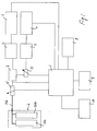
- an ultrasound imaging apparatus includes a central unit 1 which controls a transmission channel 2 having a transmitter 3. Moreover, the central unit 1 also controls a receiving channel 4 having a receiver 5. The transmitter 3 and the receiver 5 are connected to a probe 6 by means of a switching and ultrasonic beam-forming unit 7.
- Memories 8, a display screen 9 and a unit 10 for reading/writing portable storage media are further connected to the central processor unit 1.
- the probe 6 includes a plurality of transducers 106 which are connected together by the cable 206.
- the cable 206 is also connected to the switch 7, hence to the transmitter and the receiver by means of an inductance 12, whereas the probe and the cable are connected to the receiver 5 by means of both the inductance 12 and a capacitor 13 which is inserted in the circuit in parallel with the parasitic capacitance of the receiver 5.
- Figs. 2 and 3 show an equivalent circuit upon transmission and reception respectively, i.e. when the switch 7 connects the probe 6 and the cable 206 to the transmitter 3 and the receiver 5 respectively. While the transmission and receiving channels are physically joined by a separator circuit, i.e. the switching unit 7, the equivalent circuits thereof are different. Particularly, upon transmission, the transmitter 3 operates like a low impedance generator, whereas the assembly composed of the probe 6 and the cable 206 actually forms a resonant circuit. Conversely, upon reception, the receiver 5 operates like a resonant circuit, whereas the probe-cable assembly operates like a low to medium impedance generator.
- the following tuning condition may be used for oscillating resonant circuits:
- the corresponding oscillating circuit may be calibrated, i.e. the circuit formed by said probe-cable assembly may be calibrated to the resonance frequency corresponding to the fundamental frequency of transmission pulses, and the circuit formed by the receiver may be calibrated to the selected harmonic of the fundamental transmission frequency, particularly to the second harmonic.
- the resonance frequency of the circuit in combination with said compensating inductance Lc of 15 ⁇ H results to be 4 MHz, i.e. at the second harmonic of the fundamental frequency of the transmitted pulse.
- a compensating capacitor Cc may be placed in parallel to Cr, so that Cc + Cr are approximately equal to Cp/4. This allows to maintain the tuning inductance on an optimized value for transmission and to also tune the transmitting resonant circuit.
- the tuning inductance may be set on the receiver, and a compensating capacitor may be considered which, in combination with said tuning inductance, optimizes tuning of the transmitting resonant circuit.
- the optimized tuning inductance may be directly mounted on the probe-cable assembly, regardless of the specific ultrasound imaging machine, as the transmitting resonant circuit is tuned regardless of the characteristics of the transmitter 3.
- each probe-connecting cable assembly would have its own tuning inductance which is determined based on the electric characteristics of said specific assembly.
- the latter might be set after selecting a predetermined assembly, if the tuning capacitor provided with the probe and the cable could not allow optimized tuning of the receiving resonant circuit.
- the probe 6 might include a memory 306 for storing the relevant electric data for tuning the receiving resonant circuit, and particularly the value of the compensating inductance associated to the probe and the value of the equivalent capacitor of the probe-cable assembly.
- the central processing unit 1 might read data from the memory 306 of the probe 6. Based on said data, the processing unit 1 may first determine if a compensating capacitor is to be set for the receiving channel. When a compensating capacitor is needed, said processing unit may secondly determine the value of said compensating capacitor and set a variable capacitor provided in the receiving channel parallel to the parasitic capacitance of the receiver 5 to said capacitance value.
- the memory 306 of the probe may only contain one identification code
- the memory 8 may contain several tables of data relating to several different probe-cable assemblies, as well as a software program for reading the identification code stored 306 in the probe 6 and for comparing it with the list of identification codes included in the memory 8 and uniquely associated to tables of electric data of the assembly identified by said code whereby, once the data table whose code coincides with the one read from the memory 306 of the probe is found, the procedure of setting the compensating capacitor of the receiving resonant circuit is executed as described above.
- the comparing program directly requests data through a message, e.g. displayed on the screen 9 or transmitted by any other means, possibly sound.
- a portable magnetic medium may be provided in combination with the probe, with the corresponding data table stored therein, which may be read 10 by the machine by means of a special reader 10, whereby the data may be loaded into the memory 8 and the set up procedure may be executed as described above.
- the above procedures may be executed in a manner similar to the installation of drivers for computer devices or the like, like plug and play procedures.
- the set up procedure as described above for the compensating capacitor of the resonant circuit in the receiving channel is also applicable to the resonant circuit tuning inductance in the transmission channel.
- the inductance might not be placed on the probe-cable assembly, but at the input of the ultrasound imaging machine.
- the ultrasound imaging machine may be arranged to automatically or semiautomatically set said tuning inductance to an optimized value for the probe-cable assembly being used. It shall be noted that, here again, all the above considered options for setting the compensating capacitor to tune the resonant circuit in the receiving channel may be provided. It shall be further noted that, in the same manner as the compensating capacitor may be set to zero, i.e.
- variable tuning inductance provided inside the ultrasound imaging machine may be reduced to zero or by-passed, if the probe already has a tuning inductance integrated thereon, as this would result from the information provided either automatically by the memory integrated in the probe or by the tables contained in the memory of the ultrasound imaging machine, or by the data contained in any portable storage media.
- the invention allows to remove or reduce the spurious signal components upon transmission.
- the resonant circuit may be tuned directly on the probe, regardless of the ultrasound imaging machine in use.
- the provision of a tuning inductance also has an effect on the receiving channel, which is also similar to a resonant circuit, to be tuned in most cases to the second harmonic resonance frequency already based on the tuning inductance for the transmitting resonant circuit.
- the transmitting and/or receiving resonant circuits may be tuned in several possibly automatic or semiautomatic manners. Particularly, by coupling the receiving channel to the probe through a resonant circuit which is tuned or may be tuned to the second harmonic frequency, any contribution to the received signal due to the second harmonic may be separated from those at the fundamental frequency, without using the complex filtering procedures currently required, or anyway limiting the use of said procedures.
- the method and apparatus of this invention find use in any ultrasound imaging mode, particularly in any ultrasound imaging mode using contrast agents and/or received signals at a harmonic of the fundamental frequency of the transmitted pulses.
- the method according to the present invention may be combined with any other kind of ultrasound imaging method for example with a multiple pulse technique employing modulated wavelets which provide coding upon transmission and correlated filtering upon reception, wherein the term wavelets includes arbitrary analog signals not having discrete times and amplitudes as well as pulse sequences having discrete times and amplitudes.
- the method according to the invention may be combined with a so called Pulse Inversion technique, in which only a few components of the at least two successive transmitted pulses are inverted, whereas the other components are not inverted, the received signals being summed together as described in US 5,706,819.
- a further improvement may provide the method according to the present invention in combination with a multi pulse technique, in which an even number of pulses half of which is inverted with respect of the other half number of the said pulses are transmitted and the received signals relating to all or al least part of these transmitted pulses is summed together.
- a multi pulse technique in which an even number of pulses half of which is inverted with respect of the other half number of the said pulses are transmitted and the received signals relating to all or al least part of these transmitted pulses is summed together.
- the order of transmission of the said four pulses being of any kind, particularly the normal and inverted pulses are transmitted alternatively one to the other or the two inverted pulses are transmitted directly one after the other as the first two, the last two or the intermediate two pulses.
- the method according to the present invention may be combined with an imaging technique providing the emission of two successive transmission pulses and the reception of the two reflection echo signals generated by said transmission pulses and in which means are provided for differentiating the two reflected echo signals from each other.
Abstract
Description
Claims (58)
Applications Claiming Priority (2)
| Application Number | Priority Date | Filing Date | Title |
|---|---|---|---|
| ITSV20010030 | 2001-08-14 | ||
| IT2001SV000030A ITSV20010030A1 (en) | 2001-08-14 | 2001-08-14 | METHOD AND DEVICE FOR THE TRANSMISSION OF ULTRASONIC PULSES AND THE RECEPTION OF THE ECHO SIGNALS TO A HARMONIC OF THE TRANSMISSION FREQUENCY |
Publications (3)
| Publication Number | Publication Date |
|---|---|
| EP1293802A2 true EP1293802A2 (en) | 2003-03-19 |
| EP1293802A3 EP1293802A3 (en) | 2003-04-23 |
| EP1293802B1 EP1293802B1 (en) | 2014-02-19 |
Family
ID=11457104
Family Applications (1)
| Application Number | Title | Priority Date | Filing Date |
|---|---|---|---|
| EP02017366.2A Expired - Lifetime EP1293802B1 (en) | 2001-08-14 | 2002-08-02 | Ultrasound system and method for receiving echo signals at a harmonic of the transmission frequency |
Country Status (3)
| Country | Link |
|---|---|
| US (1) | US7458935B2 (en) |
| EP (1) | EP1293802B1 (en) |
| IT (1) | ITSV20010030A1 (en) |
Cited By (2)
| Publication number | Priority date | Publication date | Assignee | Title |
|---|---|---|---|---|
| WO2015120132A1 (en) * | 2014-02-07 | 2015-08-13 | The Regents Of The University Of California | Frequency tuning and/or frequency tracking of a mechanical system with low sensitivity to electrical feedthrough |
| CN109124680A (en) * | 2017-06-16 | 2019-01-04 | 美国西门子医疗解决公司 | It is used to form the method and ultrasonic system of the ultrasonic signal of ultrasonic probe |
Families Citing this family (12)
| Publication number | Priority date | Publication date | Assignee | Title |
|---|---|---|---|---|
| EP2267481A1 (en) * | 2003-11-26 | 2010-12-29 | Teratech Corporation | Modular portable ultrasound systems |
| US20080281205A1 (en) * | 2004-01-16 | 2008-11-13 | Morteza Naghavi | Methods and Apparatuses For Medical Imaging |
| JP5154554B2 (en) | 2006-08-01 | 2013-02-27 | ボストン サイエンティフィック サイムド,インコーポレイテッド | Pulse inversion sequence for nonlinear imaging |
| JP5195587B2 (en) * | 2009-03-31 | 2013-05-08 | 株式会社デンソー | Ultrasonic sensor |
| US10772602B2 (en) * | 2014-11-25 | 2020-09-15 | Koninklijke Philips N.V. | System for monitoring a use of a medical device |
| US10585178B2 (en) * | 2015-10-21 | 2020-03-10 | Semiconductor Componenents Industries, Llc | Piezo transducer controller and method having adaptively-tuned linear damping |
| KR20180041507A (en) | 2016-10-14 | 2018-04-24 | 삼성메디슨 주식회사 | A ultrasound imaging apparatus and control method thereof |
| US10856843B2 (en) | 2017-03-23 | 2020-12-08 | Vave Health, Inc. | Flag table based beamforming in a handheld ultrasound device |
| US10469846B2 (en) | 2017-03-27 | 2019-11-05 | Vave Health, Inc. | Dynamic range compression of ultrasound images |
| US11531096B2 (en) | 2017-03-23 | 2022-12-20 | Vave Health, Inc. | High performance handheld ultrasound |
| US11446003B2 (en) | 2017-03-27 | 2022-09-20 | Vave Health, Inc. | High performance handheld ultrasound |
| US11504093B2 (en) * | 2021-01-22 | 2022-11-22 | Exo Imaging, Inc. | Equalization for matrix based line imagers for ultrasound imaging systems |
Citations (5)
| Publication number | Priority date | Publication date | Assignee | Title |
|---|---|---|---|---|
| EP0770352A1 (en) | 1995-10-10 | 1997-05-02 | Advanced Technology Laboratories, Inc. | Ultrasonic diagnostic imaging with contrast agents |
| US5706819A (en) | 1995-10-10 | 1998-01-13 | Advanced Technology Laboratories, Inc. | Ultrasonic diagnostic imaging with harmonic contrast agents |
| US5833614A (en) | 1997-07-15 | 1998-11-10 | Acuson Corporation | Ultrasonic imaging method and apparatus for generating pulse width modulated waveforms with reduced harmonic response |
| US5902243A (en) | 1998-04-15 | 1999-05-11 | Acuson Corporation | Ultrasonic imaging method with multiple pulse cancellation |
| US6050947A (en) | 1998-04-20 | 2000-04-18 | General Electric Company | Method and apparatus for harmonic tissue imaging and contrast imaging using coded transmission |
Family Cites Families (10)
| Publication number | Priority date | Publication date | Assignee | Title |
|---|---|---|---|---|
| JPS57203434A (en) * | 1981-06-08 | 1982-12-13 | Tokyo Shibaura Electric Co | Ultrasonic diagnostic apparatus |
| GB2212267B (en) * | 1987-11-11 | 1992-07-29 | Circulation Res Ltd | Methods and apparatus for the examination and treatment of internal organs |
| DE69331692T2 (en) * | 1992-09-16 | 2002-10-24 | Hitachi Ltd | ULTRASCHALLBESTRAHLUNGSGERAET |
| JPH06225881A (en) * | 1993-02-01 | 1994-08-16 | Aloka Co Ltd | Ultrasonic diagnostic device |
| US5724976A (en) * | 1994-12-28 | 1998-03-10 | Kabushiki Kaisha Toshiba | Ultrasound imaging preferable to ultrasound contrast echography |
| US6104670A (en) * | 1995-03-02 | 2000-08-15 | Acuson Corporation | Ultrasonic harmonic imaging system and method |
| JPH08280681A (en) * | 1995-04-12 | 1996-10-29 | Fujitsu Ltd | Ultrasonic diagnostic apparatus |
| US5632277A (en) * | 1996-06-28 | 1997-05-27 | Siemens Medical Systems, Inc. | Ultrasound imaging system employing phase inversion subtraction to enhance the image |
| US6213947B1 (en) * | 1999-03-31 | 2001-04-10 | Acuson Corporation | Medical diagnostic ultrasonic imaging system using coded transmit pulses |
| US6241676B1 (en) * | 1999-06-10 | 2001-06-05 | Agilent Technologies, Inc. | Ultrasound transmit waveforms having low harmonic content |
-
2001
- 2001-08-14 IT IT2001SV000030A patent/ITSV20010030A1/en unknown
-
2002
- 2002-08-02 EP EP02017366.2A patent/EP1293802B1/en not_active Expired - Lifetime
- 2002-08-13 US US10/217,779 patent/US7458935B2/en active Active
Patent Citations (5)
| Publication number | Priority date | Publication date | Assignee | Title |
|---|---|---|---|---|
| EP0770352A1 (en) | 1995-10-10 | 1997-05-02 | Advanced Technology Laboratories, Inc. | Ultrasonic diagnostic imaging with contrast agents |
| US5706819A (en) | 1995-10-10 | 1998-01-13 | Advanced Technology Laboratories, Inc. | Ultrasonic diagnostic imaging with harmonic contrast agents |
| US5833614A (en) | 1997-07-15 | 1998-11-10 | Acuson Corporation | Ultrasonic imaging method and apparatus for generating pulse width modulated waveforms with reduced harmonic response |
| US5902243A (en) | 1998-04-15 | 1999-05-11 | Acuson Corporation | Ultrasonic imaging method with multiple pulse cancellation |
| US6050947A (en) | 1998-04-20 | 2000-04-18 | General Electric Company | Method and apparatus for harmonic tissue imaging and contrast imaging using coded transmission |
Cited By (5)
| Publication number | Priority date | Publication date | Assignee | Title |
|---|---|---|---|---|
| WO2015120132A1 (en) * | 2014-02-07 | 2015-08-13 | The Regents Of The University Of California | Frequency tuning and/or frequency tracking of a mechanical system with low sensitivity to electrical feedthrough |
| US10284208B2 (en) | 2014-02-07 | 2019-05-07 | The Regents Of The University Of California | Frequency tuning and/or frequency tracking of a mechanical system with low sensitivity to electrical feedthrough |
| CN109124680A (en) * | 2017-06-16 | 2019-01-04 | 美国西门子医疗解决公司 | It is used to form the method and ultrasonic system of the ultrasonic signal of ultrasonic probe |
| CN109124680B (en) * | 2017-06-16 | 2021-09-07 | 美国西门子医疗解决公司 | Method for forming an ultrasound signal of an ultrasound probe and ultrasound system |
| US11303270B2 (en) | 2017-06-16 | 2022-04-12 | Siemens Medical Solutions Usa, Inc. | Pulse cancellation compensation method for contrast agent imaging |
Also Published As
| Publication number | Publication date |
|---|---|
| US20030036704A1 (en) | 2003-02-20 |
| EP1293802B1 (en) | 2014-02-19 |
| EP1293802A3 (en) | 2003-04-23 |
| ITSV20010030A1 (en) | 2003-02-14 |
| US7458935B2 (en) | 2008-12-02 |
Similar Documents
| Publication | Publication Date | Title |
|---|---|---|
| EP1293802B1 (en) | Ultrasound system and method for receiving echo signals at a harmonic of the transmission frequency | |
| US8047994B2 (en) | Ultrasound imaging method combined with the presence of contrast media in the body under examination | |
| US4584880A (en) | Tissue signature tracking tranceiver | |
| US5218869A (en) | Depth dependent bandpass of ultrasound signals using heterodyne mixing | |
| EP1122556A9 (en) | Enhanced tissue-generated harmonic imaging using coded excitation | |
| EP1121901A2 (en) | Angle independent ultrasound volume flow measurement | |
| EP1609423A2 (en) | Ultrasonic diagnostic apparatus | |
| US6626836B2 (en) | Adaptive signal processing scheme for contrast agent imaging | |
| US5261280A (en) | Tissue signature tracking transceiver | |
| EP0193899A1 (en) | Tissue signature tracking transceiver having upconverted if amplification | |
| WO2005091885A3 (en) | System and method for vascular border detection | |
| CN108348220A (en) | For needle visually adaptively deflection adjustment | |
| US4413520A (en) | Ultrasonic imaging apparatus | |
| CN111447879B (en) | Ultrasonic probe transducer testing | |
| US20030060712A1 (en) | Ultrasonic diagnosis apparatus and ultrasound imaging method | |
| US20100137715A1 (en) | Ultrasonic imaging apparatus and control method for ultrasonic imaging apparatus | |
| US10571436B2 (en) | Transducer array CMUT element biasing | |
| CN109799284B (en) | Multi-harmonic self-adaptive separation method for ultrasonic echo signals | |
| US20040133104A1 (en) | Detection of a coherent reflector in noisy ultrasound data | |
| US6047601A (en) | Self-tuning crystal notch filter | |
| JPH06225881A (en) | Ultrasonic diagnostic device | |
| JPS63221241A (en) | Ultrasonic diagnosing device | |
| US20050251008A1 (en) | System and method for filtering in imaging systems | |
| JP3889986B2 (en) | Ultrasonic diagnostic equipment | |
| CN116999088A (en) | Method for removing inherent interference in ultrasonic diagnostic system |
Legal Events
| Date | Code | Title | Description |
|---|---|---|---|
| PUAI | Public reference made under article 153(3) epc to a published international application that has entered the european phase |
Free format text: ORIGINAL CODE: 0009012 |
|
| PUAL | Search report despatched |
Free format text: ORIGINAL CODE: 0009013 |
|
| AK | Designated contracting states |
Kind code of ref document: A2 Designated state(s): AT BE BG CH CY CZ DE DK EE ES FI FR GB GR IE IT LI LU MC NL PT SE SK TR Designated state(s): AT BE BG CH CY CZ DE DK EE ES FI FR GB GR IE IT LI LU MC NL PT SE SK TR |
|
| AX | Request for extension of the european patent |
Extension state: AL LT LV MK RO SI |
|
| AK | Designated contracting states |
Designated state(s): AT BE BG CH CY CZ DE DK EE ES FI FR GB GR IE IT LI LU MC NL PT SE SK TR |
|
| AX | Request for extension of the european patent |
Extension state: AL LT LV MK RO SI |
|
| 17P | Request for examination filed |
Effective date: 20030515 |
|
| AKX | Designation fees paid |
Designated state(s): AT BE BG CH CY CZ DE DK EE ES FI FR GB GR IE IT LI LU MC NL PT SE SK TR |
|
| RAP1 | Party data changed (applicant data changed or rights of an application transferred) |
Owner name: ESAOTE S.P.A. |
|
| RAP1 | Party data changed (applicant data changed or rights of an application transferred) |
Owner name: ESAOTE S.P.A. |
|
| RAP1 | Party data changed (applicant data changed or rights of an application transferred) |
Owner name: ESAOTE S.P.A. |
|
| 17Q | First examination report despatched |
Effective date: 20100426 |
|
| REG | Reference to a national code |
Ref country code: DE Ref legal event code: R079 Ref document number: 60245998 Country of ref document: DE Free format text: PREVIOUS MAIN CLASS: G01S0015890000 Ipc: G01S0007520000 |
|
| RAP1 | Party data changed (applicant data changed or rights of an application transferred) |
Owner name: ESAOTE S.P.A. |
|
| GRAP | Despatch of communication of intention to grant a patent |
Free format text: ORIGINAL CODE: EPIDOSNIGR1 |
|
| RIC1 | Information provided on ipc code assigned before grant |
Ipc: G01S 15/89 20060101ALI20130923BHEP Ipc: G01S 7/52 20060101AFI20130923BHEP |
|
| INTG | Intention to grant announced |
Effective date: 20131014 |
|
| RAP1 | Party data changed (applicant data changed or rights of an application transferred) |
Owner name: ESAOTE S.P.A. |
|
| GRAS | Grant fee paid |
Free format text: ORIGINAL CODE: EPIDOSNIGR3 |
|
| GRAA | (expected) grant |
Free format text: ORIGINAL CODE: 0009210 |
|
| AK | Designated contracting states |
Kind code of ref document: B1 Designated state(s): AT BE BG CH CY CZ DE DK EE ES FI FR GB GR IE IT LI LU MC NL PT SE SK TR |
|
| REG | Reference to a national code |
Ref country code: GB Ref legal event code: FG4D |
|
| REG | Reference to a national code |
Ref country code: CH Ref legal event code: EP |
|
| REG | Reference to a national code |
Ref country code: AT Ref legal event code: REF Ref document number: 652904 Country of ref document: AT Kind code of ref document: T Effective date: 20140315 |
|
| REG | Reference to a national code |
Ref country code: DE Ref legal event code: R096 Ref document number: 60245998 Country of ref document: DE Effective date: 20140403 |
|
| REG | Reference to a national code |
Ref country code: IE Ref legal event code: FG4D |
|
| REG | Reference to a national code |
Ref country code: NL Ref legal event code: VDEP Effective date: 20140219 |
|
| REG | Reference to a national code |
Ref country code: AT Ref legal event code: MK05 Ref document number: 652904 Country of ref document: AT Kind code of ref document: T Effective date: 20140219 |
|
| PG25 | Lapsed in a contracting state [announced via postgrant information from national office to epo] |
Ref country code: SE Free format text: LAPSE BECAUSE OF FAILURE TO SUBMIT A TRANSLATION OF THE DESCRIPTION OR TO PAY THE FEE WITHIN THE PRESCRIBED TIME-LIMIT Effective date: 20140219 Ref country code: PT Free format text: LAPSE BECAUSE OF FAILURE TO SUBMIT A TRANSLATION OF THE DESCRIPTION OR TO PAY THE FEE WITHIN THE PRESCRIBED TIME-LIMIT Effective date: 20140619 Ref country code: ES Free format text: LAPSE BECAUSE OF FAILURE TO SUBMIT A TRANSLATION OF THE DESCRIPTION OR TO PAY THE FEE WITHIN THE PRESCRIBED TIME-LIMIT Effective date: 20140219 Ref country code: CY Free format text: LAPSE BECAUSE OF FAILURE TO SUBMIT A TRANSLATION OF THE DESCRIPTION OR TO PAY THE FEE WITHIN THE PRESCRIBED TIME-LIMIT Effective date: 20140219 Ref country code: FI Free format text: LAPSE BECAUSE OF FAILURE TO SUBMIT A TRANSLATION OF THE DESCRIPTION OR TO PAY THE FEE WITHIN THE PRESCRIBED TIME-LIMIT Effective date: 20140219 Ref country code: AT Free format text: LAPSE BECAUSE OF FAILURE TO SUBMIT A TRANSLATION OF THE DESCRIPTION OR TO PAY THE FEE WITHIN THE PRESCRIBED TIME-LIMIT Effective date: 20140219 Ref country code: NL Free format text: LAPSE BECAUSE OF FAILURE TO SUBMIT A TRANSLATION OF THE DESCRIPTION OR TO PAY THE FEE WITHIN THE PRESCRIBED TIME-LIMIT Effective date: 20140219 |
|
| PG25 | Lapsed in a contracting state [announced via postgrant information from national office to epo] |
Ref country code: BE Free format text: LAPSE BECAUSE OF FAILURE TO SUBMIT A TRANSLATION OF THE DESCRIPTION OR TO PAY THE FEE WITHIN THE PRESCRIBED TIME-LIMIT Effective date: 20140219 |
|
| PG25 | Lapsed in a contracting state [announced via postgrant information from national office to epo] |
Ref country code: DK Free format text: LAPSE BECAUSE OF FAILURE TO SUBMIT A TRANSLATION OF THE DESCRIPTION OR TO PAY THE FEE WITHIN THE PRESCRIBED TIME-LIMIT Effective date: 20140219 Ref country code: CZ Free format text: LAPSE BECAUSE OF FAILURE TO SUBMIT A TRANSLATION OF THE DESCRIPTION OR TO PAY THE FEE WITHIN THE PRESCRIBED TIME-LIMIT Effective date: 20140219 Ref country code: EE Free format text: LAPSE BECAUSE OF FAILURE TO SUBMIT A TRANSLATION OF THE DESCRIPTION OR TO PAY THE FEE WITHIN THE PRESCRIBED TIME-LIMIT Effective date: 20140219 |
|
| REG | Reference to a national code |
Ref country code: DE Ref legal event code: R097 Ref document number: 60245998 Country of ref document: DE |
|
| PG25 | Lapsed in a contracting state [announced via postgrant information from national office to epo] |
Ref country code: SK Free format text: LAPSE BECAUSE OF FAILURE TO SUBMIT A TRANSLATION OF THE DESCRIPTION OR TO PAY THE FEE WITHIN THE PRESCRIBED TIME-LIMIT Effective date: 20140219 |
|
| PLBE | No opposition filed within time limit |
Free format text: ORIGINAL CODE: 0009261 |
|
| STAA | Information on the status of an ep patent application or granted ep patent |
Free format text: STATUS: NO OPPOSITION FILED WITHIN TIME LIMIT |
|
| 26N | No opposition filed |
Effective date: 20141120 |
|
| REG | Reference to a national code |
Ref country code: DE Ref legal event code: R097 Ref document number: 60245998 Country of ref document: DE Effective date: 20141120 |
|
| PG25 | Lapsed in a contracting state [announced via postgrant information from national office to epo] |
Ref country code: MC Free format text: LAPSE BECAUSE OF FAILURE TO SUBMIT A TRANSLATION OF THE DESCRIPTION OR TO PAY THE FEE WITHIN THE PRESCRIBED TIME-LIMIT Effective date: 20140219 Ref country code: LU Free format text: LAPSE BECAUSE OF FAILURE TO SUBMIT A TRANSLATION OF THE DESCRIPTION OR TO PAY THE FEE WITHIN THE PRESCRIBED TIME-LIMIT Effective date: 20140802 |
|
| REG | Reference to a national code |
Ref country code: CH Ref legal event code: PL |
|
| PG25 | Lapsed in a contracting state [announced via postgrant information from national office to epo] |
Ref country code: CH Free format text: LAPSE BECAUSE OF NON-PAYMENT OF DUE FEES Effective date: 20140831 Ref country code: LI Free format text: LAPSE BECAUSE OF NON-PAYMENT OF DUE FEES Effective date: 20140831 |
|
| REG | Reference to a national code |
Ref country code: IE Ref legal event code: MM4A |
|
| PG25 | Lapsed in a contracting state [announced via postgrant information from national office to epo] |
Ref country code: IE Free format text: LAPSE BECAUSE OF NON-PAYMENT OF DUE FEES Effective date: 20140802 |
|
| PG25 | Lapsed in a contracting state [announced via postgrant information from national office to epo] |
Ref country code: BG Free format text: LAPSE BECAUSE OF FAILURE TO SUBMIT A TRANSLATION OF THE DESCRIPTION OR TO PAY THE FEE WITHIN THE PRESCRIBED TIME-LIMIT Effective date: 20140219 |
|
| PG25 | Lapsed in a contracting state [announced via postgrant information from national office to epo] |
Ref country code: GR Free format text: LAPSE BECAUSE OF FAILURE TO SUBMIT A TRANSLATION OF THE DESCRIPTION OR TO PAY THE FEE WITHIN THE PRESCRIBED TIME-LIMIT Effective date: 20140520 |
|
| REG | Reference to a national code |
Ref country code: FR Ref legal event code: PLFP Year of fee payment: 15 |
|
| PG25 | Lapsed in a contracting state [announced via postgrant information from national office to epo] |
Ref country code: TR Free format text: LAPSE BECAUSE OF FAILURE TO SUBMIT A TRANSLATION OF THE DESCRIPTION OR TO PAY THE FEE WITHIN THE PRESCRIBED TIME-LIMIT Effective date: 20140219 |
|
| REG | Reference to a national code |
Ref country code: FR Ref legal event code: PLFP Year of fee payment: 16 |
|
| REG | Reference to a national code |
Ref country code: FR Ref legal event code: PLFP Year of fee payment: 17 |
|
| PGFP | Annual fee paid to national office [announced via postgrant information from national office to epo] |
Ref country code: DE Payment date: 20200810 Year of fee payment: 19 Ref country code: FR Payment date: 20200810 Year of fee payment: 19 Ref country code: GB Payment date: 20200810 Year of fee payment: 19 |
|
| PGFP | Annual fee paid to national office [announced via postgrant information from national office to epo] |
Ref country code: IT Payment date: 20210805 Year of fee payment: 20 |
|
| REG | Reference to a national code |
Ref country code: DE Ref legal event code: R119 Ref document number: 60245998 Country of ref document: DE |
|
| GBPC | Gb: european patent ceased through non-payment of renewal fee |
Effective date: 20210802 |
|
| PG25 | Lapsed in a contracting state [announced via postgrant information from national office to epo] |
Ref country code: GB Free format text: LAPSE BECAUSE OF NON-PAYMENT OF DUE FEES Effective date: 20210802 Ref country code: FR Free format text: LAPSE BECAUSE OF NON-PAYMENT OF DUE FEES Effective date: 20210831 Ref country code: DE Free format text: LAPSE BECAUSE OF NON-PAYMENT OF DUE FEES Effective date: 20220301 |