EP1411368A1 - Ultrasonic diagnostic apparatus and ultrasonic diagnostic method - Google Patents
Ultrasonic diagnostic apparatus and ultrasonic diagnostic method Download PDFInfo
- Publication number
- EP1411368A1 EP1411368A1 EP20030023279 EP03023279A EP1411368A1 EP 1411368 A1 EP1411368 A1 EP 1411368A1 EP 20030023279 EP20030023279 EP 20030023279 EP 03023279 A EP03023279 A EP 03023279A EP 1411368 A1 EP1411368 A1 EP 1411368A1
- Authority
- EP
- European Patent Office
- Prior art keywords
- signal
- power
- frequency component
- ultrasound
- electric signal
- Prior art date
- Legal status (The legal status is an assumption and is not a legal conclusion. Google has not performed a legal analysis and makes no representation as to the accuracy of the status listed.)
- Withdrawn
Links
Images


Classifications
-
- G—PHYSICS
- G01—MEASURING; TESTING
- G01S—RADIO DIRECTION-FINDING; RADIO NAVIGATION; DETERMINING DISTANCE OR VELOCITY BY USE OF RADIO WAVES; LOCATING OR PRESENCE-DETECTING BY USE OF THE REFLECTION OR RERADIATION OF RADIO WAVES; ANALOGOUS ARRANGEMENTS USING OTHER WAVES
- G01S7/00—Details of systems according to groups G01S13/00, G01S15/00, G01S17/00
- G01S7/52—Details of systems according to groups G01S13/00, G01S15/00, G01S17/00 of systems according to group G01S15/00
- G01S7/52017—Details of systems according to groups G01S13/00, G01S15/00, G01S17/00 of systems according to group G01S15/00 particularly adapted to short-range imaging
- G01S7/52023—Details of receivers
- G01S7/52036—Details of receivers using analysis of echo signal for target characterisation
- G01S7/52038—Details of receivers using analysis of echo signal for target characterisation involving non-linear properties of the propagation medium or of the reflective target
-
- G—PHYSICS
- G01—MEASURING; TESTING
- G01S—RADIO DIRECTION-FINDING; RADIO NAVIGATION; DETERMINING DISTANCE OR VELOCITY BY USE OF RADIO WAVES; LOCATING OR PRESENCE-DETECTING BY USE OF THE REFLECTION OR RERADIATION OF RADIO WAVES; ANALOGOUS ARRANGEMENTS USING OTHER WAVES
- G01S7/00—Details of systems according to groups G01S13/00, G01S15/00, G01S17/00
- G01S7/52—Details of systems according to groups G01S13/00, G01S15/00, G01S17/00 of systems according to group G01S15/00
- G01S7/52017—Details of systems according to groups G01S13/00, G01S15/00, G01S17/00 of systems according to group G01S15/00 particularly adapted to short-range imaging
- G01S7/52077—Details of systems according to groups G01S13/00, G01S15/00, G01S17/00 of systems according to group G01S15/00 particularly adapted to short-range imaging with means for elimination of unwanted signals, e.g. noise or interference
-
- G—PHYSICS
- G01—MEASURING; TESTING
- G01N—INVESTIGATING OR ANALYSING MATERIALS BY DETERMINING THEIR CHEMICAL OR PHYSICAL PROPERTIES
- G01N2291/00—Indexing codes associated with group G01N29/00
- G01N2291/02—Indexing codes associated with the analysed material
- G01N2291/024—Mixtures
- G01N2291/02491—Materials with nonlinear acoustic properties
-
- G—PHYSICS
- G01—MEASURING; TESTING
- G01S—RADIO DIRECTION-FINDING; RADIO NAVIGATION; DETERMINING DISTANCE OR VELOCITY BY USE OF RADIO WAVES; LOCATING OR PRESENCE-DETECTING BY USE OF THE REFLECTION OR RERADIATION OF RADIO WAVES; ANALOGOUS ARRANGEMENTS USING OTHER WAVES
- G01S7/00—Details of systems according to groups G01S13/00, G01S15/00, G01S17/00
- G01S7/52—Details of systems according to groups G01S13/00, G01S15/00, G01S17/00 of systems according to group G01S15/00
- G01S7/52017—Details of systems according to groups G01S13/00, G01S15/00, G01S17/00 of systems according to group G01S15/00 particularly adapted to short-range imaging
- G01S7/52046—Techniques for image enhancement involving transmitter or receiver
- G01S7/52047—Techniques for image enhancement involving transmitter or receiver for elimination of side lobes or of grating lobes; for increasing resolving power
Definitions
- the present invention relates to an ultrasonic diagnostic apparatus, and especially relates to technology for reducing an artifact (a virtual image) contained in an ultrasound image.
- the ultrasonic diagnostic apparatus which enables to observe an object to be tested in a noninvasive and real time manner, has been an irreplaceable existence in a medical field.
- the ultrasonic diagnostic apparatus is an apparatus that sends an ultrasonic pulse generated by a probe (a search unit) to the object, and visualizes condition in the object into an image according to an ultrasonic echo reflected.
- a probe a search unit
- the ultrasonic diagnostic apparatus sends an ultrasonic pulse generated by a probe (a search unit) to the object, and visualizes condition in the object into an image according to an ultrasonic echo reflected.
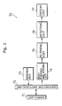
- Fig. 1 is a block diagram that shows a functional configuration of the conventional ultrasonic diagnostic apparatus 70.
- the conventional ultrasonic diagnostic apparatus 70 is composed of a search unit 71, a send/receive switching unit 72, a sending unit 73, a beam forming and adding unit 74, a filtering unit 75, a detecting unit 76 and a display unit 77.
- the search unit 71 is an apparatus that sends an ultrasonic pulse to an object to be examined, and receives an ultrasonic (hereinafter referred to as an "ultrasonic echo") reflected from the object.
- an ultrasonic hereinafter referred to as an "ultrasonic echo”
- the search unit 71 receives a pulse signal (hereinafter referred to as a "transmission pulse signal”) to generate the ultrasonic pulse from the sending unit 73, and generates the ultrasonic pulse based on this.
- the search unit 71 when the search unit 71 receives the ultrasonic echo, the search unit 71 converts the ultrasonic echo reflected from the object into an electric signal (hereinafter referred to as a "received echo signal"), and outputs it to the send/receive switching unit 72.
- a received echo signal an electric signal
- the send/receive switching unit 72 connects the search unit 71 with the spending unit 73.
- the send/receive switching unit 72 switches the search unit 71 to connect with the sending unit 73.
- the sending unit 73 generates the transmission pulse signal, and outputs it to the send/receive switching unit 72.
- the beam forming and adding unit 74 executes focusing and all necessary beam formation and addition to the received echo signal that is received from the search unit 71 via the send/receive switching unit 72, and outputs it to the filtering unit 75.
- the filtering unit 75 executes a filtering process to the received echo signal output from the beam forming and adding unit 74.
- the detecting unit 76 executes envelope detection to the received echo signal, which has been processed through the filtering process and output from the filtering process 75, and outputs the received echo signal after the detection process (hereinafter referred to as a "received detection signal") to the display unit 77.
- the display unit 77 generates an ultrasonic image based on the received detection signal output from the detecting unit 76.
- the transmission pulse signal is generated in the sending unit 73.
- the ultrasonic pulse generated based on this transmission pulse signal is sent to the object from the search unit 71.
- the ultrasonic pulse sent to the object is reflected at a sound impedance boundary within the object, and comes back to the search unit 71 with time delay caused according to a reflection depth after the transmission has been started.
- the search unit 71 converts the received ultrasonic echo into the received electric echo signal, and outputs it to the beam forming and adding unit 74.
- the beam form and adding unit 74 corrects the difference in the receiving time when each of the oscillators composing the search unit 71 receives the ultrasonic echo, and executes focusing on the received echo signal.
- a filtering process by a band path filter is executed for efficiently extracting the received echo signal in the harmonics frequency, which is a central frequency or twice of the central frequency in the filtering unit 75.
- the received echo signal that has been through the filtering unit 75 is multiplexed by using a Hilbert conversion filter in detecting unit 76. Then, after that, by applying the envelope detection to it, it is converted into the received detection signal which shows luminance for generating an ultrasonic image, and the like.
- the display unit 77 generates the ultrasonic image based on the received detection signal, and displays it on a display apparatus, or the like.
- an ultrasonic pulse having desired directivity for example, a feature to have a stronger acoustic pressure in a front direction
- desired directivity for example, a feature to have a stronger acoustic pressure in a front direction
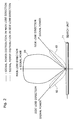
- the ultrasonic pulse actually sent contains a plural number of side lobes sent in an undesired direction (for example, 45 degrees in both right and left directions) in addition to the main lobe sent in a desired direction (in the front direction).
- Fig. 2 is a diagram that shows overview of a plural number of side lobes 82 and 83, which are generated at both sides of a main lobe 81 and sent in undesired directions (i.e. in right and left oblique directions. Hereinafter it is referred to as a "side lobe direction"). Because of these side lobes, the side lobe of the ultrasonic pulse is sent to an object located in the side lobe direction.
- the ultrasonic diagnostic apparatus 70 When the ultrasonic diagnostic apparatus 70 receives the ultrasonic echo, it receives the ultrasonic echo reflected from the object located in the side lobe direction at the same time it also receives the main lobe of the ultrasonic pulse reflected from the object that can reflect the ultrasound to be displayed as the ultrasound image. As a result of it, the ultrasonic echo reflected from the object located in the side lobe direction generated an artifact (a virtual image), and causes a problem to induce misdiagnosis through the ultrasound image containing the artifact (Please see the above reference book).
- an artifact a virtual image
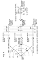
- Fig. 3 is a pattern diagram to show a process that the artifact (a virtual image) generated by the above side lobes 82 and 83 are displayed as the ultrasound image.
- the artifact a virtual image
- this ultrasonic pulse contains the side lobe.
- objects 93 ⁇ 95 located in both right and left side lobe directions, which are not desired to be displayed as the ultrasound image and from which the ultrasound may be reflected, these objects reflect the side lobe so that the received echo signals 93a ⁇ 95a are generated.
- the signals 93a ⁇ 95a through the above side lobe remain even in the received detection signal, and these appear as the artifact.
- the present invention aims at providing an ultrasonic diagnostic apparatus and an ultrasonic diagnostic method for preventing any wrong diagnosis due to an artifact (a virtual image) caused by a side lobe.
- the ultrasonic diagnostic apparatus may be an ultrasonic diagnostic apparatus that generates and displays an ultrasonic image of an object to be examined based on reflection of ultrasound having a main lobe and a side lobe, comprising: an ultrasonic sending/receiving unit operable to generate the ultrasound, receive the ultrasound reflected from the object, and convert the ultrasound into an electric signal; a first calculating unit operable to extract a fundamental wave frequency component from the converted electric signal and calculate power of the signal; a second calculating unit operable to extract a harmonics frequency component from the converted electric signal and calculate power of the signal; a power ratio calculating unit operable to calculate a ratio of the calculated power of the signal of the fundamental frequency component to the calculated power of the signal of the harmonics frequency component; an output controlling unit operable to control and output the electric signal of the fundamental wave frequency component based on a value of the calculated ratio; and an image display unit operable to generate and display an ultrasonic image based on the output electric signal.
- the ultrasonic diagnostic apparatus related to the present invention is an ultrasonic diagnostic apparatus that generates and displays a ultrasonic image of an object to be examined based on reflection of ultrasound having a main lobe and a side lobe, comprising: an ultrasound sending/receiving unit operable to generate the ultrasound, receive the ultrasound reflected from the object, and convert the ultrasound into an electric signal; a first calculating unit operable to extract a fundamental wave frequency component from the converted electric signal and calculate power of the signal; a second calculating unit operable to extract a harmonics frequency component from the converted electric signal and calculate power of the signal; a power ratio calculating unit operable to calculate a ratio of the calculated power of the signal of the fundamental frequency component to the calculated power of the signal of the harmonics frequency component; an output controlling unit operable to control and output the electric signal of the harmonics frequency component based on a value of the calculated ratio; and an image display unit operable to generate and display an ultrasonic image based on the output electric signal.
- the present invention may be embodied as a method having characteristic and structural means of the above ultrasonic diagnostic apparatus as steps, and may also be embodied as a program containing all of these steps. Then, the program is not only be stored in a ROM and the like that are contained in the ultrasonic diagnostic apparatus, but it may also be distributed through a recording media such as a CD-ROM or a transmission media such as a communication network.
- the ultrasonic diagnostic apparatus decides whether the received detection signal is a signal to generate the artifact or not, by using a difference between the transmission power in the main lobe direction and the transmission power in the side lobe direction within the ultrasonic pulse sent from the search unit and a difference in degree of the nonlinear diffusion distortion phenomenon contained in the object to be examined. Based on this result, the output level of the received detection signal is suppressed, and the above artifact is reduced, of which practical value is high.
- the main lobe direction has a wide spread in a transmission direction, even lateral resolving power can be improved by appropriately setting the power ratio threshold value used in the present invention.
- Fig. 4 is an outlook view of the ultrasonic diagnostic apparatus 10 according to the present embodiment.
- An apparatus 10 is an ultrasonic diagnostic apparatus, which does not just generate an ultrasonic image, but also reduces an artifact (a virtual image) generated by a side lobe and is capable of providing more accurate diagnosis.
- the ultrasonic diagnostic apparatus 10 is mainly composed of a display unit 10a, a main unit 10b and a probe 10c.
- the display unit 10a is a display apparatus equipped with a liquid crystal display (LCD), a cathode-ray tube (CRT), or the like, which displays an ultrasound image and all necessary information obtained through an ultrasonic echo method and the like, and includes a touch panel and the like that accept an input from an operator.
- LCD liquid crystal display
- CRT cathode-ray tube
- the main unit 10b includes the following elements: a send/receive circuit that controls transmission/reception of an ultrasound in the probe 10c; a signal/image processing circuit containing a digital signal processor (DSP) and a random access memory (RAM) and the like for processing various types of images and signals; an LCD display containing a group of switches and a mouse and a touch panel for receiving the operator's operation; and so on.
- a send/receive circuit that controls transmission/reception of an ultrasound in the probe 10c
- a signal/image processing circuit containing a digital signal processor (DSP) and a random access memory (RAM) and the like for processing various types of images and signals
- DSP digital signal processor
- RAM random access memory
- the probe 10c is a search unit containing an ultrasonic oscillator, an acoustic lens and the like for receiving and sending the ultrasound.
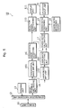
- Fig. 5 is a block diagram that shows a functional configuration of the ultrasonic diagnostic apparatus 10 according to the present embodiment.
- this apparatus 10 includes the following elements: a search unit 11; a send/receive switching unit 12; a sending unit 13; a beam forming and adding unit 14; a fundamental wave BPF (band path filtering) unit 151; a harmonics BPF unit 152; a harmonics detecting unit 162; a power ratio calculating unit 17; a power ratio reference memory 18; a power ratio comparing unit 19; an operation input unit 20; a detection signal suppressing unit 110; and a display unit 111.
- a search unit 11 includes the following elements: a search unit 11; a send/receive switching unit 12; a sending unit 13; a beam forming and adding unit 14; a fundamental wave BPF (band path filtering) unit 151; a harmonics BPF unit 152; a harmonics detecting unit 162; a power ratio calculating unit 17; a power ratio reference memory 18
- the search unit 11 is a unit that generates the ultrasonic pulse and receives the ultrasonic echo reflected from the object (equivalent to the probe 10c in the above Fig. 4). When the ultrasonic pulse is sent, this search unit 11 generates the ultrasonic pulse based on the transmission pulse signal received from the sending unit 13. On the other hand, when the ultrasonic echo is received, the search unit 11 converts the ultrasonic echo reflected from the object into a received echo signal, and outputs this received echo signal to the send/receive switching unit 12.
- the send/receive switching unit 12 When the ultrasonic pulse is sent, the send/receive switching unit 12 connects the search unit 11 with the sending unit 13. When the ultrasonic pulse is received, the send/receive switching unit 12 switches the search unit 11 to connect with the beam forming and adding unit 14.
- the sending unit 13 When the ultrasonic pulse is sent, the sending unit 13 generates a transmission pulse signal, and outputs it to the send/receive switching unit 12.
- the beam forming and adding unit 14 executes focusing for the received echo signal that is received from the search unit 11 via the send/receive switching unit 12, and applies the necessary beam formation and addition.
- the fundamental wave BPF unit 151 executes a filtering process to the received echo signal output from the beam forming and adding unit 14 for extracting a signal component of central frequency corresponding to the fundamental wave of the ultrasonic pulse.
- the harmonics BPF unit 152 executes a filtering process to the received echo signal output from the beam forming and adding unit 14 for extracting a signal component of harmonics frequency composing non-linear distortion occurred when the fundamental wave of the ultrasonic pulse diffuses in the object.
- the fundamental wave detecting unit 161 executes detection to the signal component of the central frequency of the received echo signal output from the fundamental wave BPF unit 151.
- the harmonics detecting unit 162 executes detection to the signal component of the harmonics frequency of the received echo signal output from the harmonics BPF unit 152.
- the power ratio calculating unit 17 calculates a power ratio in the received detection signal respectively output from the fundamental wave detecting unit 161 and the harmonics detecting unit 162 (for example, a maximum amplitude value of the received detection signal of the harmonics/a maximum amplitude value of the received detection signal of the fundamental wave).
- the power ratio reference memory 18 stores a "power ratio threshold value" set per diffusion distance (or may be called as a "depth") in the object.
- the power ratio threshold value is a standard value used for deciding whether the received detection signal is based on the main lobe or based on the side lobe. When the power ratio is less than this value, the received detection signal is decided to be the received detection signal based on the side lobe.
- the diffusion distance and the power ratio threshold value are corresponded and memorized. For example, when the spread distance (depth) is "5cm”, the power ratio threshold value is "0.3”. When the spread distance (depth) is "10cm”, the power ratio threshold value is "0.35". This power ratio threshold value may be changed by a user via the operation input unit 20.
- the power ratio comparing unit 19 compares a "power ratio”, which is an output of the power ratio calculating unit 17, with its corresponding "power ratio threshold value” by each diffusion distance (depth), which is stored in the power ratio reference memory 18.
- the power ratio comparing unit 19 notifies its result (i.e. "it is an artifact", “it is not an artifact” and the like.) to the detection signal suppressing unit 110.
- the power ratio is "0.1" in the case of the diffusion distance (depth) is "5 cm”
- its corresponding power ratio threshold value is "0.3”
- the power ratio comparing unit 19 decides it is an artifact based on the side lobe.
- the detection signal suppressing unit 110 controls the output of the fundamental wave detecting unit 161 based on the notice received from the power ratio comparing unit 19. For example, when the detection signal suppressing unit 110 receives a notice that "it is a side lobe" from the power ratio comparing unit 19, it controls the received detection signal of the fundamental wave. For example, the detection signal suppressing unit 110 reduces it to 20 percent when outputting it, or does not output it at all.
- the display unit 111 generates an ultrasonic image based on the echo signal, which is an output of the detection signal suppressing unit 110, and displays it.
- the sending unit 13 At first, for sending the ultrasonic pulse to the object, the sending unit 13 generates a transmission pulse signal, and sends it to the search unit 11. In addition, the search unit 11 generates an ultrasonic pulse based on this transmission pulse signal, and sends it to the object.
- the ultrasonic pulse that is sent from the search unit 11 contains a main lobe and a side lobe. Due to this, the ultrasonic pulse (side lobe) is also sent to an object located in the side lobe direction. Therefore, when the ultrasonic diagnostic apparatus 10 receives the ultrasonic echo, it does not receive only the ultrasonic echo reflected from an object desired to be displayed as a diagnostic image located in the main lobe direction, but also it receives the ultrasonic echo reflected from the object located in the side lobe direction. As a result of it, the ultrasonic pulse from the side lobe direction is displayed as an artifact (a virtual image).
- the first point is a difference between the transmission power in the main lobe direction and the transmission power in the side lobe direction within the transmitted ultrasonic pulse. That is to say, as clarified from the above Fig. 2, the transmission power in the main lobe direction is bigger than the transmission power in the side lobe direction.
- the second point is a phenomenon of nonlinear diffusion distortion occurred when the ultrasonic pulse goes through the object. This phenomenon is a phenomenon that a wave form of the ultrasonic pulse is gradually distorted as the transmitted ultrasonic pulse diffuses in the object. According to diffusion distance (depth), the ultrasonic pulse has more harmonics frequency components in the transmitted frequency (the fundamental frequency), which is N times (twice, three times, or the like) as much as the one in a regular transmitted frequency (the fundamental wave frequency).
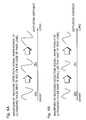
- Fig. 6 is a pattern diagram showing the phenomenon of nonlinear diffusion distortion occurred when the ultrasonic pulse diffuses in the object.
- Fig. 6A is an example of a wave form of the received echo signal wave in the event that the power of the ultrasonic pulse sent is big (i.e. in the event of the main lobe).
- Fig. 6B is an example of the received echo signal wave form for a case the power of the ultrasonic pulse sent is small (i.e. in the event of the side lobe).
- the wave form of the received echo signal becomes more saw-toothed.
- this phenomenon of nonlinear diffusion distortion is closely related to power strength, either small or big, of the transmission ultrasonic pulse.
- the nonlinear diffusion distortion occurs in shorter diffusion distance (depth) compared with a case when the power is small.
- big harmonics occur in shorter diffusion distance (depth).
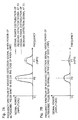
- Fig. 7 is a diagram that typically shows the frequency spectrum of the received detection signal in the nonlinear diffusion distortion phenomenon described in the above Fig. 6.
- Fig. 6A is an example of the frequency spectrum of the received detection signal for a case the power of the transmission ultrasonic pulse is big (i.e. in the event of the main lobe).
- Fig. 6B is an example of the frequency spectrum of the received detection signal for a case the power of the transmission ultrasonic pulse is small (i.e. in the event of the side lobe).
- Fig. 7A shows signal power distribution of the received echo signal when the diffusion distance is at Z0 and Z1 for a case the power of the transmission ultrasonic pulse is big.
- Fig. 7B shows signal power distribution of the received detection signal when the diffusion distance is at Z0 and Z1 for a case the power of the transmission ultrasonic pulse is small. In this case, the signal power of the harmonics frequency does not substantially get bigger even if the diffusion distance is longer.
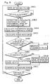
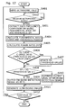
- Fig. 8 is a flow chart that shows a flow of actions of the ultrasonic diagnostic apparatus 10.
- the ultrasonic pulse is sent to the object (S401)
- the ultrasonic pulse is reflected at a sound impedance boundary within the object, and it comes back to the search unit 11 with some time delay occurred according to the reflection depth after transmission has started (S402).
- the ultrasonic echo received by this search unit 11 is received in a way that reflection waves from the main lobe direction and the side lobe direction are superimposed each other.
- the ultrasonic echo received by the search unit 11 is converted into the received echo signal and sent to the beam forming and adding unit 14.
- the beam forming and adding unit 14 corrects the difference in the reaching time spent by the received echo signal between oscillators that form the search unit 11, and execute focusing on the received echo signal.
- the fundamental wave frequency component is extracted and its signal power is calculated by using the fundamental wave BPF unit 151 and the fundamental wave detecting unit 161 (S403, S404).
- the harmonics frequency component is extracted and its signal power is calculated by using the harmonics BPF unit 152 and the harmonics detecting unit 162 (S403, S404).
- the power ratio calculating unit 17 calculates a ratio Rp of each signal power calculated by the fundamental wave detecting unit 161 and the harmonics detecting unit 162 (S405).
- the power ratio comparing unit 19 compares the power ratio Rp calculated by the power ratio calculating unit 17 with the power ratio threshold value Rs memorized by each diffusion distance (depth), which is stored in the power ratio reference memory 18, and make a notification based on its comparison result to the detection signal suppressing unit 110.
- the detection signal suppressing unit 110 suppresses a signal level of the received detection signal output from the fundamental wave detecting unit 161 (S410) (for example, it suppresses it to 20 percent). If not, it keeps the same signal level of the received detection signal output from the fundamental wave detecting unit 161 (S409).
- the display unit 111 generates an ultrasonic image based the received detection signal output from the detection signal suppressing unit 110, and displays it (S411). These processes mentioned above are continued until the diagnosis using the ultrasonic diagnostic apparatus is completed (S401 ⁇ S412).
- the received detection signal which is input to the detection signal suppressing unit 110, is regarded as the received echo signal output from the fundamental wave detecting unit 161.
- the received detection signal output from the harmonics detecting unit 162 shall be used as its input.
- the ultrasonic diagnostic apparatus 10 related to the present embodiment, detection and suppression of the received echo signal generated by the side lobe, which is a cause of the artifact contained in the ultrasonic echo, are conducted by calculating and comparing the power ratios of "harmonics power/fundamental wave power" in the received detection signal. Therefore, it is possible to generate a clear ultrasonic image, which has fewer artifacts, as the ultrasonic image displayed on the display unit 111, and prevent misdiagnosis.
- an ultrasonic diagnostic apparatus is an ultrasonic diagnostic apparatus that can reduce an artifact by suppressing a level of the received detection signal generated by the side lobe in the ultrasonic pulse.
- this ultrasonic diagnostic apparatus is especially different from the ultra diagnostic apparatus according to the firs embodiment with respect to a point that it uses a dynamic band path filter as a band path filter for extracting a fundamental wave frequency component or a harmonics frequency component.
- Fig. 9 is a block diagram that shows a functional configuration of an ultrasonic diagnostic apparatus 40 according to the present embodiment.
- the ultrasonic diagnostic apparatus 40 includes the following elements: a search unit 41; a send/receive switching unit 42; a sending unit 43; a beam forming and adding unit 44; a fundamental wave DBPF (a dynamic band path filter) unit 451; a DBPF (a dynamic band path filter) unit 452; a fundamental wave detecting unit 461; a harmonics detecting unit 462; a power ratio calculating unit 47; a power ratio reference memory 48; a power ratio comparing unit 49; a detection signal suppressing unit 410; and a display unit 411.
- the configuration of the ultrasonic diagnostic apparatus according to the second embodiment is almost the same as the one of the first embodiment, the following explanation focuses on components, which are different. Because the search unit 41, the send/receive switching unit 42, the sending unit 43, the beam forming and adding unit 44, the fundamental wave detecting unit 461, the harmonics detecting unit 462, the power ratio calculating unit 47, the power ratio reference memory 48, the power ratio comparing unit 49, the detection signal suppressing unit 410 and the display unit 411 in Fig.
- the search unit 11 the send/receive switching unit 12, the sending unit 13, the beam forming and adding unit 14, the fundamental wave detecting unit 161, the harmonics detecting unit 162, the power ratio calculating unit 17, the power ratio reference memory 18, the power ratio comparing unit 19, the detection signal suppressing unit 110 and the display unit 111 in the ultrasonic diagnostic apparatus 10 according to the aforementioned first embodiment, their explanation is omitted here.
- the fundamental wave DBPF unit 451 and the harmonics DBPF unit 452 have a filtering feature of which band path width dynamically moves to a lower frequency band width, as the receiving depth gets deeper.
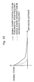
- a reason why the BPF having such feature is used is because it has a characteristic that the signal power is remarkably attenuated as the frequency gets higher, which is as shown in Fig. 10, though the power of the transmitted ultrasonic pulse is attenuated according to diffusion distance (depth).
- Fig. 11 shows an example of the frequency feature of this dynamic band path filter.
- the dynamic band path filter By using the dynamic band path filter, it becomes possible to control the band path bandwidth to be changed according to the diffusion distance (depth) in a dynamic way. Therefore, it is possible to obtain the received detection signal in a good S/N ratio, and eventually possible to generated the ultrasonic image that is unlikely to cause misdiagnosis.
- Fig. 12 is a flow chart showing a flow of actions of the ultrasonic diagnostic apparatus 40. As clarified in Fig. 12, the flow is the same as the flow in Fig. 8 according to the first embodiment except for facts that DBPF is used in the fundamental wave DBPF unit 451 and also DBPF is used in the harmonics DBPF unit 452 (S901).
- the received detection signal that is input to the detection signal suppressing unit 410 is regarded as the received detection signal output from the fundamental wave detection unit 461.
- the received detection signal output from the harmonics detecting unit 462 is used as its input.
- the ultrasonic diagnostic apparatus 40 through calculation and comparison of the power ratios of "harmonics power/fundamental wave power" in the received detection signal, the received echo signal generated by the side lobe, which is a cause of an artifact contained in the ultrasonic echo, is detected and suppressed. Additionally, the band path width is controlled to be changed in a dynamic way according to the diffusion distance (depth), and the artifact is attempted to be reduced by extracting more realistic fundamental wave frequency components and harmonics frequency components. Therefore, it is possible to generate a clearer ultrasonic image as the ultrasonic image displayed in the display unit 111, and thereby misdiagnosis can prevented.
- the explanation has been provided for a case that the artifact is attempted to be reduced by judging whether the echo signal is originated from the side lobe or not based on the ratio between the signal power of the fundamental wave frequency component and the signal power of the harmonics frequency component.
- the invention may be structured in the same way to reduce the artifact by judging whether the echo signal is originated from the side lobe or not.
Abstract
A beam forming and adding unit 14 receives an echo signal
that contains reflection by a side lobe of an ultrasonic pulse, and
executes its focusing. A fundamental wave BPF unit 151 and a
fundamental wave detecting unit 161 extract a fundamental wave
component from the echo signal, and calculates its signal power.
A harmonics BPF unit 152 and a harmonics detecting unit 162
extract a harmonics component from the echo signal, and
calculate its signal power. A power ratio calculating unit 17 and a
power ratio comparing unit 19 calculate a ratio of these two signal
powers calculated, compare this power ratio with a power ratio
threshold value stored in a power ratio reference memory 18, and
notify its comparison result to a detection signal suppressing unit
110. The detection signal suppressing unit 110 suppresses the
echo signal according to the notification result, and outputs it. A
display unit 111 generates an ultrasonic image based on the
output echo signal, and displays it.
Description
- The present invention relates to an ultrasonic diagnostic apparatus, and especially relates to technology for reducing an artifact (a virtual image) contained in an ultrasound image.
- An ultrasonic diagnostic apparatus, which enables to observe an object to be tested in a noninvasive and real time manner, has been an irreplaceable existence in a medical field. The ultrasonic diagnostic apparatus is an apparatus that sends an ultrasonic pulse generated by a probe (a search unit) to the object, and visualizes condition in the object into an image according to an ultrasonic echo reflected. (For example, see pp7-20 and pp24-25 in "Ultrasonic Medical Science TEXT Basic Ultrasonic Medical Science" written by Itoh and Hirata in April, 1998 published by Ishiyaku Shuppan Co., Ltd.)
- The following explains a configuration of a conventional ultrasonic diagnostic apparatus and actions taken by the apparatus.
- Fig. 1 is a block diagram that shows a functional configuration of the conventional ultrasonic
diagnostic apparatus 70. - As shown in Fig. 1, the conventional ultrasonic
diagnostic apparatus 70 is composed of asearch unit 71, a send/receiveswitching unit 72, asending unit 73, a beam forming and addingunit 74, afiltering unit 75, a detectingunit 76 and adisplay unit 77. - The
search unit 71 is an apparatus that sends an ultrasonic pulse to an object to be examined, and receives an ultrasonic (hereinafter referred to as an "ultrasonic echo") reflected from the object. When thesearch unit 71 sends the ultrasonic pulse, thesearch unit 71 receives a pulse signal (hereinafter referred to as a "transmission pulse signal") to generate the ultrasonic pulse from thesending unit 73, and generates the ultrasonic pulse based on this. On the other hand, when thesearch unit 71 receives the ultrasonic echo, thesearch unit 71 converts the ultrasonic echo reflected from the object into an electric signal (hereinafter referred to as a "received echo signal"), and outputs it to the send/receiveswitching unit 72. - When the ultrasonic pulse is sent, the send/receive
switching unit 72 connects thesearch unit 71 with thespending unit 73. On the other hand, when the ultrasonic pulse is received, the send/receiveswitching unit 72 switches thesearch unit 71 to connect with thesending unit 73. When the ultrasonic pulse is sent, thesending unit 73 generates the transmission pulse signal, and outputs it to the send/receiveswitching unit 72. - The beam forming and adding
unit 74 executes focusing and all necessary beam formation and addition to the received echo signal that is received from thesearch unit 71 via the send/receiveswitching unit 72, and outputs it to thefiltering unit 75. Thefiltering unit 75 executes a filtering process to the received echo signal output from the beam forming and addingunit 74. The detectingunit 76 executes envelope detection to the received echo signal, which has been processed through the filtering process and output from thefiltering process 75, and outputs the received echo signal after the detection process (hereinafter referred to as a "received detection signal") to thedisplay unit 77. Thedisplay unit 77 generates an ultrasonic image based on the received detection signal output from the detectingunit 76. - Next, actions taken in the conventional ultrasonic
diagnostic apparatus 70 are explained. For sending the ultrasonic pulse to the object, the transmission pulse signal is generated in thesending unit 73. The ultrasonic pulse generated based on this transmission pulse signal is sent to the object from thesearch unit 71. The ultrasonic pulse sent to the object is reflected at a sound impedance boundary within the object, and comes back to thesearch unit 71 with time delay caused according to a reflection depth after the transmission has been started. Thesearch unit 71 converts the received ultrasonic echo into the received electric echo signal, and outputs it to the beam forming and addingunit 74. The beam form and addingunit 74 corrects the difference in the receiving time when each of the oscillators composing thesearch unit 71 receives the ultrasonic echo, and executes focusing on the received echo signal. - In addition, because the received echo signal after the beam formation and addition contains some noise components, a filtering process by a band path filter (BPF) is executed for efficiently extracting the received echo signal in the harmonics frequency, which is a central frequency or twice of the central frequency in the
filtering unit 75. The received echo signal that has been through thefiltering unit 75 is multiplexed by using a Hilbert conversion filter in detectingunit 76. Then, after that, by applying the envelope detection to it, it is converted into the received detection signal which shows luminance for generating an ultrasonic image, and the like. Lastly, thedisplay unit 77 generates the ultrasonic image based on the received detection signal, and displays it on a display apparatus, or the like. - For the ultrasonic diagnostic apparatus, an ultrasonic pulse having desired directivity (for example, a feature to have a stronger acoustic pressure in a front direction) is used for improving picture quality of the ultrasonic image.
- However, the ultrasonic pulse actually sent contains a plural number of side lobes sent in an undesired direction (for example, 45 degrees in both right and left directions) in addition to the main lobe sent in a desired direction (in the front direction).
- Fig. 2 is a diagram that shows overview of a plural number of
side lobes main lobe 81 and sent in undesired directions (i.e. in right and left oblique directions. Hereinafter it is referred to as a "side lobe direction"). Because of these side lobes, the side lobe of the ultrasonic pulse is sent to an object located in the side lobe direction. When the ultrasonicdiagnostic apparatus 70 receives the ultrasonic echo, it receives the ultrasonic echo reflected from the object located in the side lobe direction at the same time it also receives the main lobe of the ultrasonic pulse reflected from the object that can reflect the ultrasound to be displayed as the ultrasound image. As a result of it, the ultrasonic echo reflected from the object located in the side lobe direction generated an artifact (a virtual image), and causes a problem to induce misdiagnosis through the ultrasound image containing the artifact (Please see the above reference book). - Fig. 3 is a pattern diagram to show a process that the artifact (a virtual image) generated by the
above side lobes objects echo signals objects 93 ∼ 95 located in both right and left side lobe directions, which are not desired to be displayed as the ultrasound image and from which the ultrasound may be reflected, these objects reflect the side lobe so that the receivedecho signals 93a ∼ 95a are generated. AS a result of it, thesignals 93a ∼ 95a through the above side lobe remain even in the received detection signal, and these appear as the artifact. - In the light of the above issues and problems, the present invention aims at providing an ultrasonic diagnostic apparatus and an ultrasonic diagnostic method for preventing any wrong diagnosis due to an artifact (a virtual image) caused by a side lobe.
- In order to achieve the above objective, the ultrasonic diagnostic apparatus may be an ultrasonic diagnostic apparatus that generates and displays an ultrasonic image of an object to be examined based on reflection of ultrasound having a main lobe and a side lobe, comprising: an ultrasonic sending/receiving unit operable to generate the ultrasound, receive the ultrasound reflected from the object, and convert the ultrasound into an electric signal; a first calculating unit operable to extract a fundamental wave frequency component from the converted electric signal and calculate power of the signal; a second calculating unit operable to extract a harmonics frequency component from the converted electric signal and calculate power of the signal; a power ratio calculating unit operable to calculate a ratio of the calculated power of the signal of the fundamental frequency component to the calculated power of the signal of the harmonics frequency component; an output controlling unit operable to control and output the electric signal of the fundamental wave frequency component based on a value of the calculated ratio; and an image display unit operable to generate and display an ultrasonic image based on the output electric signal.
- Additionally, to achieve the above objective, the ultrasonic diagnostic apparatus related to the present invention is an ultrasonic diagnostic apparatus that generates and displays a ultrasonic image of an object to be examined based on reflection of ultrasound having a main lobe and a side lobe, comprising: an ultrasound sending/receiving unit operable to generate the ultrasound, receive the ultrasound reflected from the object, and convert the ultrasound into an electric signal; a first calculating unit operable to extract a fundamental wave frequency component from the converted electric signal and calculate power of the signal; a second calculating unit operable to extract a harmonics frequency component from the converted electric signal and calculate power of the signal; a power ratio calculating unit operable to calculate a ratio of the calculated power of the signal of the fundamental frequency component to the calculated power of the signal of the harmonics frequency component; an output controlling unit operable to control and output the electric signal of the harmonics frequency component based on a value of the calculated ratio; and an image display unit operable to generate and display an ultrasonic image based on the output electric signal.
- Furthermore, to accomplish the above objective, the present invention may be embodied as a method having characteristic and structural means of the above ultrasonic diagnostic apparatus as steps, and may also be embodied as a program containing all of these steps. Then, the program is not only be stored in a ROM and the like that are contained in the ultrasonic diagnostic apparatus, but it may also be distributed through a recording media such as a CD-ROM or a transmission media such as a communication network.
- As mentioned above, the ultrasonic diagnostic apparatus according to the present invention decides whether the received detection signal is a signal to generate the artifact or not, by using a difference between the transmission power in the main lobe direction and the transmission power in the side lobe direction within the ultrasonic pulse sent from the search unit and a difference in degree of the nonlinear diffusion distortion phenomenon contained in the object to be examined. Based on this result, the output level of the received detection signal is suppressed, and the above artifact is reduced, of which practical value is high.
- Furthermore, because the main lobe direction has a wide spread in a transmission direction, even lateral resolving power can be improved by appropriately setting the power ratio threshold value used in the present invention. As a result, it is possible to construct an ultrasonic diagnosis apparatus that can display the ultrasonic image of which the artifact is reduced and lateral resolving power is improved.
- These and other subjects, advantages and features of the invention will become apparent from the following description thereof taken in conjunction with the accompanying drawings that illustrate a specific embodiment of the invention. In the Drawings:
- Fig. 1 is an overview diagram that shows a functional configuration of the conventional ultrasonic diagnostic apparatus.
- Fig. 2 is a diagram that typically shows conventional power distribution of the transmission pulse.
- Fig. 3 is a diagram that typically shows conventional power distribution of the received pulse according to diffusion distance.
- Fig. 4 is an outlook view of the ultrasonic diagnostic apparatus according to a first embodiment.
- Fig. 5 is a block diagram that shows a functional configuration of the ultrasonic diagnostic apparatus according to the first embodiment.
- Fig. 6 is a diagram that explains a signal wave form that is distorted by a nonlinear diffusion due to a difference in transmission power.
- Fig. 7 is an example of a signal spectrum that is distorted by a nonlinear diffusion due to a difference in transmission power.
- Fig. 8 is a flow chart that shows a flow of processes of the ultrasonic diagnostic apparatus according to the first embodiment.
- Fig. 9 is a block diagram that shows a functional configuration of the ultrasonic diagnostic apparatus according to a second embodiment.
- Fig. 10 is an example of a curve showing a relationship between diffusion distance (depth) and the received signal power.
- Fig. 11 is an example of a frequency property curve showing a relationship between diffusion distance (depth) and amplitude of the received signal.
- Fig. 12 is a flow chart that shows a flow of processes of the ultrasonic diagnostic apparatus according to the second embodiment.
-
- The following describes the present invention with reference to several embodiments and drawings.
- Fig. 4 is an outlook view of the ultrasonic
diagnostic apparatus 10 according to the present embodiment. Anapparatus 10 is an ultrasonic diagnostic apparatus, which does not just generate an ultrasonic image, but also reduces an artifact (a virtual image) generated by a side lobe and is capable of providing more accurate diagnosis. The ultrasonicdiagnostic apparatus 10 is mainly composed of adisplay unit 10a, amain unit 10b and aprobe 10c. - The
display unit 10a is a display apparatus equipped with a liquid crystal display (LCD), a cathode-ray tube (CRT), or the like, which displays an ultrasound image and all necessary information obtained through an ultrasonic echo method and the like, and includes a touch panel and the like that accept an input from an operator. - The
main unit 10b includes the following elements: a send/receive circuit that controls transmission/reception of an ultrasound in theprobe 10c; a signal/image processing circuit containing a digital signal processor (DSP) and a random access memory (RAM) and the like for processing various types of images and signals; an LCD display containing a group of switches and a mouse and a touch panel for receiving the operator's operation; and so on. - The
probe 10c is a search unit containing an ultrasonic oscillator, an acoustic lens and the like for receiving and sending the ultrasound. - Fig. 5 is a block diagram that shows a functional configuration of the ultrasonic
diagnostic apparatus 10 according to the present embodiment. As shown in Fig. 5, thisapparatus 10 includes the following elements: asearch unit 11; a send/receive switchingunit 12; a sendingunit 13; a beam forming and addingunit 14; a fundamental wave BPF (band path filtering)unit 151; aharmonics BPF unit 152; aharmonics detecting unit 162; a powerratio calculating unit 17; a powerratio reference memory 18; a powerratio comparing unit 19; anoperation input unit 20; a detectionsignal suppressing unit 110; and adisplay unit 111. - The
search unit 11 is a unit that generates the ultrasonic pulse and receives the ultrasonic echo reflected from the object (equivalent to theprobe 10c in the above Fig. 4). When the ultrasonic pulse is sent, thissearch unit 11 generates the ultrasonic pulse based on the transmission pulse signal received from the sendingunit 13. On the other hand, when the ultrasonic echo is received, thesearch unit 11 converts the ultrasonic echo reflected from the object into a received echo signal, and outputs this received echo signal to the send/receive switchingunit 12. - When the ultrasonic pulse is sent, the send/receive switching
unit 12 connects thesearch unit 11 with the sendingunit 13. When the ultrasonic pulse is received, the send/receive switchingunit 12 switches thesearch unit 11 to connect with the beam forming and addingunit 14. - When the ultrasonic pulse is sent, the sending
unit 13 generates a transmission pulse signal, and outputs it to the send/receive switchingunit 12. The beam forming and addingunit 14 executes focusing for the received echo signal that is received from thesearch unit 11 via the send/receive switchingunit 12, and applies the necessary beam formation and addition. - The fundamental
wave BPF unit 151 executes a filtering process to the received echo signal output from the beam forming and addingunit 14 for extracting a signal component of central frequency corresponding to the fundamental wave of the ultrasonic pulse. Theharmonics BPF unit 152 executes a filtering process to the received echo signal output from the beam forming and addingunit 14 for extracting a signal component of harmonics frequency composing non-linear distortion occurred when the fundamental wave of the ultrasonic pulse diffuses in the object. - The fundamental wave detecting unit 161 executes detection to the signal component of the central frequency of the received echo signal output from the fundamental
wave BPF unit 151. Theharmonics detecting unit 162 executes detection to the signal component of the harmonics frequency of the received echo signal output from theharmonics BPF unit 152. - The power
ratio calculating unit 17 calculates a power ratio in the received detection signal respectively output from the fundamental wave detecting unit 161 and the harmonics detecting unit 162 (for example, a maximum amplitude value of the received detection signal of the harmonics/a maximum amplitude value of the received detection signal of the fundamental wave). - The power
ratio reference memory 18 stores a "power ratio threshold value" set per diffusion distance (or may be called as a "depth") in the object. "The power ratio threshold value" is a standard value used for deciding whether the received detection signal is based on the main lobe or based on the side lobe. When the power ratio is less than this value, the received detection signal is decided to be the received detection signal based on the side lobe. The diffusion distance and the power ratio threshold value are corresponded and memorized. For example, when the spread distance (depth) is "5cm", the power ratio threshold value is "0.3". When the spread distance (depth) is "10cm", the power ratio threshold value is "0.35". This power ratio threshold value may be changed by a user via theoperation input unit 20. - The power
ratio comparing unit 19 compares a "power ratio", which is an output of the powerratio calculating unit 17, with its corresponding "power ratio threshold value" by each diffusion distance (depth), which is stored in the powerratio reference memory 18. The powerratio comparing unit 19 notifies its result (i.e. "it is an artifact", "it is not an artifact" and the like.) to the detectionsignal suppressing unit 110. For example, when the power ratio is "0.1" in the case of the diffusion distance (depth) is "5 cm", and its corresponding power ratio threshold value is "0.3", the powerratio comparing unit 19 decides it is an artifact based on the side lobe. - The detection
signal suppressing unit 110 controls the output of the fundamental wave detecting unit 161 based on the notice received from the powerratio comparing unit 19. For example, when the detectionsignal suppressing unit 110 receives a notice that "it is a side lobe" from the powerratio comparing unit 19, it controls the received detection signal of the fundamental wave. For example, the detectionsignal suppressing unit 110 reduces it to 20 percent when outputting it, or does not output it at all. - The
display unit 111 generates an ultrasonic image based on the echo signal, which is an output of the detectionsignal suppressing unit 110, and displays it. - Next, actions taken by the ultrasonic
diagnostic apparatus 10 according to the present embodiment are explained. - At first, for sending the ultrasonic pulse to the object, the sending
unit 13 generates a transmission pulse signal, and sends it to thesearch unit 11. In addition, thesearch unit 11 generates an ultrasonic pulse based on this transmission pulse signal, and sends it to the object. - In this case, as mentioned in the above issues that the invention attempts to resolve, the ultrasonic pulse that is sent from the
search unit 11 contains a main lobe and a side lobe. Due to this, the ultrasonic pulse (side lobe) is also sent to an object located in the side lobe direction. Therefore, when the ultrasonicdiagnostic apparatus 10 receives the ultrasonic echo, it does not receive only the ultrasonic echo reflected from an object desired to be displayed as a diagnostic image located in the main lobe direction, but also it receives the ultrasonic echo reflected from the object located in the side lobe direction. As a result of it, the ultrasonic pulse from the side lobe direction is displayed as an artifact (a virtual image). - There are two remarkable points here. The first point is a difference between the transmission power in the main lobe direction and the transmission power in the side lobe direction within the transmitted ultrasonic pulse. That is to say, as clarified from the above Fig. 2, the transmission power in the main lobe direction is bigger than the transmission power in the side lobe direction. The second point is a phenomenon of nonlinear diffusion distortion occurred when the ultrasonic pulse goes through the object. This phenomenon is a phenomenon that a wave form of the ultrasonic pulse is gradually distorted as the transmitted ultrasonic pulse diffuses in the object. According to diffusion distance (depth), the ultrasonic pulse has more harmonics frequency components in the transmitted frequency (the fundamental frequency), which is N times (twice, three times, or the like) as much as the one in a regular transmitted frequency (the fundamental wave frequency).
- Fig. 6 is a pattern diagram showing the phenomenon of nonlinear diffusion distortion occurred when the ultrasonic pulse diffuses in the object. Fig. 6A is an example of a wave form of the received echo signal wave in the event that the power of the ultrasonic pulse sent is big (i.e. in the event of the main lobe). Fig. 6B is an example of the received echo signal wave form for a case the power of the ultrasonic pulse sent is small (i.e. in the event of the side lobe). As shown in Fig. 6 (especially Fig. 6A), as the diffusion distance gets longer (the depth gets deeper), the wave form of the received echo signal becomes more saw-toothed. This is because, when the ultrasound goes through a medium (an inside of the object), it moves fast in an area where the power of the ultrasound is big (acoustic pressure is big), and it moves slowly in an area where the power of the ultrasound is small (acoustic pressure is small). Therefore, the wave form becomes saw-tooth, and the distortion as shown in Fig. 6 occurs.
- Additionally, as shown in Fig. 6A and Fig. 6B, this phenomenon of nonlinear diffusion distortion is closely related to power strength, either small or big, of the transmission ultrasonic pulse. For the same reason as above, when the power of the ultrasonic pulse is big, the nonlinear diffusion distortion occurs in shorter diffusion distance (depth) compared with a case when the power is small. In other words, when the power is big, big harmonics occur in shorter diffusion distance (depth).
- Fig. 7 is a diagram that typically shows the frequency spectrum of the received detection signal in the nonlinear diffusion distortion phenomenon described in the above Fig. 6. Fig. 6A is an example of the frequency spectrum of the received detection signal for a case the power of the transmission ultrasonic pulse is big (i.e. in the event of the main lobe). Fig. 6B is an example of the frequency spectrum of the received detection signal for a case the power of the transmission ultrasonic pulse is small (i.e. in the event of the side lobe).
- To explain this more in detail, Fig. 7A shows signal power distribution of the received echo signal when the diffusion distance is at Z0 and Z1 for a case the power of the transmission ultrasonic pulse is big. As the diffusion distance gets longer (Z1>Z0), the signal power of the harmonics frequency (F1=2F0) gets substantially bigger.
- On the other hand, Fig. 7B shows signal power distribution of the received detection signal when the diffusion distance is at Z0 and Z1 for a case the power of the transmission ultrasonic pulse is small. In this case, the signal power of the harmonics frequency does not substantially get bigger even if the diffusion distance is longer.
- From these remarkable points mentioned above, considering the power ratios of the fundamental wave frequency component and harmonics frequency component (harmonics power/fundamental wave power), it is possible to say that the ultrasonic echo received from the side lobe direction, which is a cause of the artifact (the virtual image), tends to have a smaller power ratio than the one of the ultrasonic echo received from the main lobe direction. Therefore, it is possible to reduce the artifact when the output of the received detection signal is suppressed based on this power ratio.
- Next, based on what has been mentioned in the above, the following describes actions taken by the ultrasonic
diagnostic apparatus 10 according to the first embodiment with reference to Fig. 8. Fig. 8 is a flow chart that shows a flow of actions of the ultrasonicdiagnostic apparatus 10. - At first, when the ultrasonic pulse is sent to the object (S401), the ultrasonic pulse is reflected at a sound impedance boundary within the object, and it comes back to the
search unit 11 with some time delay occurred according to the reflection depth after transmission has started (S402). It means that the ultrasonic echo received by thissearch unit 11 is received in a way that reflection waves from the main lobe direction and the side lobe direction are superimposed each other. The ultrasonic echo received by thesearch unit 11 is converted into the received echo signal and sent to the beam forming and addingunit 14. The beam forming and addingunit 14 corrects the difference in the reaching time spent by the received echo signal between oscillators that form thesearch unit 11, and execute focusing on the received echo signal. Since it is unknown whether the received echo signal after the beam formation and addition is the received echo signal based on the ultrasonic echo reflected from the main lobe, or the received echo signal based on the ultrasonic echo reflected from the side lobe, and besides the received echo signal contains noise components, the fundamental wave frequency component is extracted and its signal power is calculated by using the fundamentalwave BPF unit 151 and the fundamental wave detecting unit 161 (S403, S404). On the other hand, the harmonics frequency component is extracted and its signal power is calculated by using theharmonics BPF unit 152 and the harmonics detecting unit 162 (S403, S404). - Then, the power
ratio calculating unit 17 calculates a ratio Rp of each signal power calculated by the fundamental wave detecting unit 161 and the harmonics detecting unit 162 (S405). - Here, when the user changes the above power ratio threshold value Rs (S406), the value of the power ratio threshold value Rs stored in the power
ratio reference memory 18 is updated (S407). - In addition, the power
ratio comparing unit 19 compares the power ratio Rp calculated by the powerratio calculating unit 17 with the power ratio threshold value Rs memorized by each diffusion distance (depth), which is stored in the powerratio reference memory 18, and make a notification based on its comparison result to the detectionsignal suppressing unit 110. - If the notification received from the power
ratio comparing unit 19 shows that "it is an artifact", the detectionsignal suppressing unit 110 suppresses a signal level of the received detection signal output from the fundamental wave detecting unit 161 (S410) (for example, it suppresses it to 20 percent). If not, it keeps the same signal level of the received detection signal output from the fundamental wave detecting unit 161 (S409). - Lastly, the
display unit 111 generates an ultrasonic image based the received detection signal output from the detectionsignal suppressing unit 110, and displays it (S411). These processes mentioned above are continued until the diagnosis using the ultrasonic diagnostic apparatus is completed (S401~ S412). - In the above explanation, the received detection signal, which is input to the detection
signal suppressing unit 110, is regarded as the received echo signal output from the fundamental wave detecting unit 161. However, when an ultrasonic image display mode (Tissue Harmonics Imaging Mode) with harmonics is used, the received detection signal output from theharmonics detecting unit 162 shall be used as its input. - As has been mentioned above, according to the ultrasonic
diagnostic apparatus 10 related to the present embodiment, detection and suppression of the received echo signal generated by the side lobe, which is a cause of the artifact contained in the ultrasonic echo, are conducted by calculating and comparing the power ratios of "harmonics power/fundamental wave power" in the received detection signal. Therefore, it is possible to generate a clear ultrasonic image, which has fewer artifacts, as the ultrasonic image displayed on thedisplay unit 111, and prevent misdiagnosis. - Just as the ultrasonic
diagnostic apparatus 10 according to the first embodiment, an ultrasonic diagnostic apparatus according to the second embodiment is an ultrasonic diagnostic apparatus that can reduce an artifact by suppressing a level of the received detection signal generated by the side lobe in the ultrasonic pulse. However, this ultrasonic diagnostic apparatus is especially different from the ultra diagnostic apparatus according to the firs embodiment with respect to a point that it uses a dynamic band path filter as a band path filter for extracting a fundamental wave frequency component or a harmonics frequency component. - Fig. 9 is a block diagram that shows a functional configuration of an ultrasonic
diagnostic apparatus 40 according to the present embodiment. As shown in Fig. 9, the ultrasonicdiagnostic apparatus 40 includes the following elements: asearch unit 41; a send/receive switchingunit 42; a sendingunit 43; a beam forming and addingunit 44; a fundamental wave DBPF (a dynamic band path filter)unit 451; a DBPF (a dynamic band path filter)unit 452; a fundamentalwave detecting unit 461; aharmonics detecting unit 462; a powerratio calculating unit 47; a powerratio reference memory 48; a powerratio comparing unit 49; a detectionsignal suppressing unit 410; and adisplay unit 411. - Because the configuration of the ultrasonic diagnostic apparatus according to the second embodiment is almost the same as the one of the first embodiment, the following explanation focuses on components, which are different. Because the
search unit 41, the send/receive switchingunit 42, the sendingunit 43, the beam forming and addingunit 44, the fundamentalwave detecting unit 461, theharmonics detecting unit 462, the powerratio calculating unit 47, the powerratio reference memory 48, the powerratio comparing unit 49, the detectionsignal suppressing unit 410 and thedisplay unit 411 in Fig. 9 are the same as thesearch unit 11, the send/receive switchingunit 12, the sendingunit 13, the beam forming and addingunit 14, the fundamental wave detecting unit 161, theharmonics detecting unit 162, the powerratio calculating unit 17, the powerratio reference memory 18, the powerratio comparing unit 19, the detectionsignal suppressing unit 110 and thedisplay unit 111 in the ultrasonicdiagnostic apparatus 10 according to the aforementioned first embodiment, their explanation is omitted here. - The fundamental
wave DBPF unit 451 and theharmonics DBPF unit 452 have a filtering feature of which band path width dynamically moves to a lower frequency band width, as the receiving depth gets deeper. A reason why the BPF having such feature is used is because it has a characteristic that the signal power is remarkably attenuated as the frequency gets higher, which is as shown in Fig. 10, though the power of the transmitted ultrasonic pulse is attenuated according to diffusion distance (depth). Fig. 11 shows an example of the frequency feature of this dynamic band path filter. - By using the dynamic band path filter, it becomes possible to control the band path bandwidth to be changed according to the diffusion distance (depth) in a dynamic way. Therefore, it is possible to obtain the received detection signal in a good S/N ratio, and eventually possible to generated the ultrasonic image that is unlikely to cause misdiagnosis.
- Next, based on what has been mentioned above, actions taken by the ultrasonic
diagnostic apparatus 40 related to the second embodiment is explained with reference to Fig. 12. Fig. 12 is a flow chart showing a flow of actions of the ultrasonicdiagnostic apparatus 40. As clarified in Fig. 12, the flow is the same as the flow in Fig. 8 according to the first embodiment except for facts that DBPF is used in the fundamentalwave DBPF unit 451 and also DBPF is used in the harmonics DBPF unit 452 (S901). - In the above explanation, in the same way as the first embodiment, the received detection signal that is input to the detection
signal suppressing unit 410 is regarded as the received detection signal output from the fundamentalwave detection unit 461. However, when the ultrasonic image display mode (the Tissue Harmonics Imaging mode) with the harmonics is used, the received detection signal output from theharmonics detecting unit 462 is used as its input. - As mentioned above, according to the ultrasonic
diagnostic apparatus 40 according to the present embodiment, through calculation and comparison of the power ratios of "harmonics power/fundamental wave power" in the received detection signal, the received echo signal generated by the side lobe, which is a cause of an artifact contained in the ultrasonic echo, is detected and suppressed. Additionally, the band path width is controlled to be changed in a dynamic way according to the diffusion distance (depth), and the artifact is attempted to be reduced by extracting more realistic fundamental wave frequency components and harmonics frequency components. Therefore, it is possible to generate a clearer ultrasonic image as the ultrasonic image displayed in thedisplay unit 111, and thereby misdiagnosis can prevented. - In the first embodiment and the second embodiment mentioned above, the explanation has been provided for a case that the artifact is attempted to be reduced by judging whether the echo signal is originated from the side lobe or not based on the ratio between the signal power of the fundamental wave frequency component and the signal power of the harmonics frequency component. However, it is not limited to this. For example, based on a ratio between the signal power of the N dimensional harmonics frequency components (N: an integer of 2 or higher) and the signal power of the M dimensional harmonics frequency components (N<M, M: an integer of 3 or higher), the invention may be structured in the same way to reduce the artifact by judging whether the echo signal is originated from the side lobe or not.
Claims (16)
- An ultrasonic diagnostic apparatus that generates and displays an ultrasonic image of an object to be examined based on reflection of ultrasound having a main lobe and a side lobe, comprising:an ultrasonic sending/receiving unit operable to generate the ultrasound, receive the ultrasound reflected from the object, and convert the ultrasound into an electric signal;a first calculating unit operable to extract a fundamental wave frequency component from the converted electric signal and calculate power of the signal;a second calculating unit operable to extract a harmonics frequency component from the converted electric signal and calculate power of the signal;a power ratio calculating unit operable to calculate a ratio of the calculated power of the signal of the fundamental frequency component to the calculated power of the signal of the harmonics frequency component;an output controlling unit operable to control and output the electric signal of the fundamental wave frequency component based on a value of the calculated ratio; andan image display unit operable to generate and display an ultrasonic image based on the output electric signal.
- An ultrasonic diagnostic apparatus that generates and displays a ultrasonic image of an object to be examined based on reflection of ultrasound having a main lobe and a side lobe, comprising:an ultrasound sending/receiving unit operable to generate the ultrasound, receive the ultrasound reflected from the object, and convert the ultrasound into an electric signal;a first calculating unit operable to extract a fundamental wave frequency component from the converted electric signal and calculate power of the signal;a second calculating unit operable to extract a harmonics frequency component from the converted electric signal and calculate power of the signal;a power ratio calculating unit operable to calculate a ratio of the calculated power of the signal of the fundamental frequency component to the calculated power of the signal of the harmonics frequency component;an output controlling unit operable to control and output the electric signal of the harmonics frequency component based on a value of the calculated ratio; andan image display unit operable to generate and display an ultrasonic image based on the output electric signal.
- The ultrasonic diagnostic apparatus according to Claim 1 or 2,
wherein the output controlling unit compares the power ratio with a specific power ratio threshold value, and performs the control based on a comparison result. - The ultrasonic diagnostic apparatus according to Claim 3,
wherein the output controlling unit decides, when the power ratio is the same as or less than the power ratio threshold value, that the electric signal is an electric signal based on the side lobe, and suppresses and outputs a signal level of the electric signals. - The ultrasonic diagnostic apparatus according to Claim 4, further comprising a threshold value updating unit operable to accept an operational input from a user, and update content of the power ratio threshold value based on the accepted operational input, and
wherein the output controlling unit makes the comparison based on the updated power ratio threshold value. - The ultrasonic diagnostic apparatus according to Claim 1,
wherein the first calculating unit extracts the fundamental wave frequency component by using a dynamic band path filter, and
the second calculating unit extracts the harmonics frequency component by using a dynamic band path filter. - An ultrasonic diagnostic apparatus that generates and displays an ultrasonic image of an object to be examined based on reflection of ultrasound having a main lobe and a side lobe, comprising:an ultrasound sending/receiving unit operable to generate the ultrasound, receive the ultrasound reflected from the object, and convert the ultrasound into an electric signal;a first calculating unit operable to extract an N dimensional harmonics frequency component (N: an integer of 2 or more) from the converted electric signal, and calculate power of the signal;a second calculating unit operable to extract an M dimensional harmonics frequency component (N<M, M: an integer of 3 or more) from the converted electric signal, and calculate power of the signal;a power ratio calculating unit operable to calculate a ratio of the calculated power of the signal of the N dimensional harmonics frequency component to the calculated power of the signal of the M dimensional harmonics frequency component;an output controlling unit operable to control and output the electric signal of the N dimensional harmonics frequency component based on a value of the calculated ratio; andan image display unit operable to generate and display an ultrasonic image based on the output electric signal.
- An ultrasonic diagnostic apparatus that generates and displays an ultrasonic image of an object to be examined based on reflection of ultrasound having a main lobe and a side lobe, comprising:an ultrasound sending/receiving unit operable to generate the ultrasound, receive the ultrasound reflected from the object, and convert the ultrasound into an electric signal;a first calculating unit operable to extract an N dimensional harmonics frequency component (N: an integer of 2 or more) from the converted electric signal, and calculate power of the signal;a second calculating unit operable to extract an M dimensional harmonics frequency component (N<M, M: an integer of 3 or more) from the converted electric signal, and calculate power of the signal;a power ratio calculating unit operable to calculate a ratio of the calculated power of the signal of the N dimensional harmonics frequency component to the calculated power of the signal of the M dimensional harmonics frequency component;an output controlling unit operable to control and output the electric signal of the M dimensional harmonics frequency component based on a value of the calculated ratio; andan image display unit operable to generate and display an ultrasonic image based on the output electric signal.
- An ultrasonic diagnostic method for generating and displaying an ultrasonic image of an object to be examined based on reflection of ultrasound having a main lobe and a side lobe, comprising:an ultrasound sending/receiving step of generating the ultrasound, receiving the ultrasound reflected from the object, and converting the ultrasound into an electric signal;a first calculating step of extracting a fundamental wave frequency component from the converted electric signal, and calculating power of the signal;a second calculating step of extracting a harmonics frequency component from the converted electric signal, and calculating power of the signal;a power ratio calculating step of calculating a ratio of the calculated power of the signal of the fundamental frequency component to the calculated power of the signal of the harmonics frequency component;an output controlling step of controlling and outputting the electric signal of the fundamental wave frequency component based on a value of the calculated ratio; andan image display step of generating and displaying an ultrasonic image based on the output electric signal.
- An ultrasonic diagnostic method for generating and displaying an ultrasonic image of an object to be examined based on reflection of ultrasound having a main lobe and a side lobe, comprising:an ultrasound sending/receiving step of generating the ultrasound, receiving the ultrasound reflected from the object, and converting the ultrasound into an electric signal;a first calculating step of extracting a fundamental wave frequency component from the converted electric signal, and calculating power of the signal;a second calculating step of extracting a harmonics frequency component from the converted electric signal, and calculating power of the signal;a power ratio calculating step of calculating a ratio of the calculated power of the signal of the fundamental frequency component to the calculated power of the signal of the harmonics frequency component;an output controlling step of controlling and outputting the electric signal of the harmonics frequency component based on a value of the calculated ratio; andan image display step of generating and displaying an ultrasonic image based on the output electric signal.
- The ultrasonic diagnostic method according to Claim 9 or 10,
wherein at the output controlling step, the power ratio is compared with a specific power ratio threshold value, and the control based on a comparison result is performed. - The ultrasonic diagnostic method according to Claim 9 or 11,
Wherein at the output controlling step, when the power ratio is the same as or less than the power ratio threshold value, it is decided that the electric signal is an electric signal based on the side lobe, and a signal level of the electric signals is suppressed and output. - An ultrasonic diagnostic method for generating and displaying an ultrasonic image of an object to examined based on reflection of ultrasound having a main lobe and a side lobe, comprising:an ultrasound sending/receiving step of generating the ultrasound, receiving the ultrasound reflected from the object, and converting the ultrasound into an electric signal;a first calculating step of extracting an N dimensional harmonics frequency component (N: an integer of 2 or more) from the converted electric signal, and calculating power of the signal;a second calculating step of extracting an M dimensional harmonics frequency component (N<M, M: an integer of 3 or more) from the converted electric signal, and calculating power of the signal;a power ratio operation step of calculating a ratio of the calculated power of the signal of the N dimensional harmonics frequency component to the calculated power of the signal of the M dimensional harmonics frequency component;an output controlling step of controlling and outputting the electric signal of the N dimensional harmonics frequency component based on a value of the calculated ratio; andan image display step of generating and displaying an ultrasohic image based on the output electric signal.
- An ultrasonic diagnostic apparatus that generates and displays an ultrasonic image of an object to examined based on reflection of ultrasound having a main lobe and a side lobe, comprising:an ultrasound sending/receiving step of generating the ultrasound, receiving the ultrasound reflected from the object, and converting the ultrasound into an electric signal;a first calculating step of extracting an N dimensional harmonics frequency component (N: an integer of 2 or more) from the converted electric signal, and calculating power of the signal;a second calculating step of extracting an M dimensional harmonics frequency component (N<M, M: an integer of 3 or more) from the converted electric signal, and calculating power of the signal;a power ratio operation step of calculating a ratio of the calculated power of the signal of the N dimensional harmonics frequency component to the calculated power of the signal of the M dimensional harmonics frequency component;an output controlling step of controlling and outputting the electric signal of the M dimensional harmonics frequency component based on a value of the calculated ratio; andan image display step of generating and display an ultrasonic image based on the output electric signal.
- A program for an ultrasonic diagnostic apparatus that generates and displays an ultrasonic image of an object to examined based on reflection of ultrasound having a main lobe and a side lobe, comprising:an ultrasound sending/receiving step of generating the ultrasound, receiving the ultrasound reflected from the object, and converting the ultrasound into an electric signal;a first calculating step of extracting a fundamental wave frequency component from the converted electric signal, and calculating power of the signal;a second calculating step of extracting a harmonics frequency component from the converted electric signal, and calculating power of the signal;a power ratio operation step of calculating a ratio of the calculated power of the signal of the fundamental frequency component to the calculated power of the signal of the harmonics frequency component;an output controlling step of controlling and outputting the electric signal of the fundamental wave frequency component based on a value of the calculated ratio; andan image display step of generating and displaying an ultrasonic image based on the output electric signal.
- A program for an ultrasonic diagnostic apparatus that generates and displays an ultrasonic image of an object to be examined based on reflection of ultrasound having a main lobe and a side lobe, comprising:an ultrasound sending/receiving step of generating the ultrasound, receiving the ultrasound reflected from the object, and converting the ultrasound into an electric signal;a first calculating step of extracting a fundamental wave frequency component from the converted electric signal, and calculating power of the signal;a second calculating step of extracting a harmonics frequency component from the converted electric signal, and calculating power of the signal;a power ratio operation step of calculating a ratio of the calculated power of the signal of the fundamental frequency component to the calculated power of the signal of the harmonics frequency component;an output controlling step of controlling and outputting the electric signal of the harmonics frequency component based on a value of the calculated ratio; andan image display step of generating and displaying an ultrasonic image based on the output electric signal.
Applications Claiming Priority (2)
| Application Number | Priority Date | Filing Date | Title |
|---|---|---|---|
| JP2002300957 | 2002-10-15 | ||
| JP2002300957A JP2004135705A (en) | 2002-10-15 | 2002-10-15 | Ultrasonograph and ultrasonic diagnostic method |
Publications (1)
| Publication Number | Publication Date |
|---|---|
| EP1411368A1 true EP1411368A1 (en) | 2004-04-21 |
Family
ID=32040791
Family Applications (1)
| Application Number | Title | Priority Date | Filing Date |
|---|---|---|---|
| EP20030023279 Withdrawn EP1411368A1 (en) | 2002-10-15 | 2003-10-15 | Ultrasonic diagnostic apparatus and ultrasonic diagnostic method |
Country Status (3)
| Country | Link |
|---|---|
| US (1) | US6923766B2 (en) |
| EP (1) | EP1411368A1 (en) |
| JP (1) | JP2004135705A (en) |
Cited By (1)
| Publication number | Priority date | Publication date | Assignee | Title |
|---|---|---|---|---|
| EP2871475A1 (en) * | 2013-11-07 | 2015-05-13 | Mitsubishi Hitachi Power Systems, Ltd. | Ultrasonic testing sensor and ultrasonic testing method |
Families Citing this family (4)
| Publication number | Priority date | Publication date | Assignee | Title |
|---|---|---|---|---|
| US6988410B2 (en) * | 2003-10-24 | 2006-01-24 | General Electric Company | Inspection method and apparatus for determining incipient mechanical failure |
| US7546769B2 (en) * | 2005-12-01 | 2009-06-16 | General Electric Compnay | Ultrasonic inspection system and method |
| JP2013000351A (en) * | 2011-06-16 | 2013-01-07 | Hitachi Aloka Medical Ltd | Ultrasonic diagnostic apparatus |
| KR101858137B1 (en) * | 2017-03-08 | 2018-05-16 | 대진대학교 산학협력단 | Method For Evaluating Filters That Suppress Sidelobes In Ultrasound Images Using Computer Simulations |
Citations (4)
| Publication number | Priority date | Publication date | Assignee | Title |
|---|---|---|---|---|
| US5235985A (en) * | 1992-04-30 | 1993-08-17 | Mcmorrow Gerald J | Automatic bladder scanning apparatus |
| US6132377A (en) * | 1999-03-31 | 2000-10-17 | Acuson Corporation | Medical diagnostic ultrasonic imaging system and method using differential sub-band detection techniques |
| US6181810B1 (en) * | 1998-07-30 | 2001-01-30 | Scimed Life Systems, Inc. | Method and apparatus for spatial and temporal filtering of intravascular ultrasonic image data |
| US6221018B1 (en) * | 1997-07-15 | 2001-04-24 | Acuson Corporation | Medical ultrasonic diagnostic imaging method and apparatus |
Family Cites Families (6)
| Publication number | Priority date | Publication date | Assignee | Title |
|---|---|---|---|---|
| DE4137256A1 (en) | 1991-03-29 | 1992-10-01 | Deutsche Forsch Luft Raumfahrt | FLEXIBLE BAND LEADER |
| US5526816A (en) * | 1994-09-22 | 1996-06-18 | Bracco Research S.A. | Ultrasonic spectral contrast imaging |
| US5961460A (en) * | 1997-04-11 | 1999-10-05 | Acuson Corporation | Ultrasound imaging enhancement methods and systems |
| US5833614A (en) * | 1997-07-15 | 1998-11-10 | Acuson Corporation | Ultrasonic imaging method and apparatus for generating pulse width modulated waveforms with reduced harmonic response |
| US5913823A (en) * | 1997-07-15 | 1999-06-22 | Acuson Corporation | Ultrasound imaging method and system for transmit signal generation for an ultrasonic imaging system capable of harmonic imaging |
| US5961464A (en) * | 1998-09-16 | 1999-10-05 | Hewlett-Packard Company | Ultrasound contrast agent detection using spectral analysis from acoustic scan lines |
-
2002
- 2002-10-15 JP JP2002300957A patent/JP2004135705A/en active Pending
-
2003
- 2003-10-14 US US10/682,931 patent/US6923766B2/en not_active Expired - Fee Related
- 2003-10-15 EP EP20030023279 patent/EP1411368A1/en not_active Withdrawn
Patent Citations (4)
| Publication number | Priority date | Publication date | Assignee | Title |
|---|---|---|---|---|
| US5235985A (en) * | 1992-04-30 | 1993-08-17 | Mcmorrow Gerald J | Automatic bladder scanning apparatus |
| US6221018B1 (en) * | 1997-07-15 | 2001-04-24 | Acuson Corporation | Medical ultrasonic diagnostic imaging method and apparatus |
| US6181810B1 (en) * | 1998-07-30 | 2001-01-30 | Scimed Life Systems, Inc. | Method and apparatus for spatial and temporal filtering of intravascular ultrasonic image data |
| US6132377A (en) * | 1999-03-31 | 2000-10-17 | Acuson Corporation | Medical diagnostic ultrasonic imaging system and method using differential sub-band detection techniques |
Cited By (4)
| Publication number | Priority date | Publication date | Assignee | Title |
|---|---|---|---|---|
| EP2871475A1 (en) * | 2013-11-07 | 2015-05-13 | Mitsubishi Hitachi Power Systems, Ltd. | Ultrasonic testing sensor and ultrasonic testing method |
| CN104634880A (en) * | 2013-11-07 | 2015-05-20 | 三菱日立电力系统株式会社 | Utrasonic testing sensor and ultrasonic testing method |
| US9435769B2 (en) | 2013-11-07 | 2016-09-06 | Mitsubishi Hitachi Power Systems, Ltd. | Ultrasonic testing sensor and ultrasonic testing method |
| CN104634880B (en) * | 2013-11-07 | 2017-08-08 | 三菱日立电力系统株式会社 | Ultrasonic examination sensor and defect detection on ultrasonic basis |
Also Published As
| Publication number | Publication date |
|---|---|
| JP2004135705A (en) | 2004-05-13 |
| US6923766B2 (en) | 2005-08-02 |
| US20040077947A1 (en) | 2004-04-22 |
Similar Documents
| Publication | Publication Date | Title |
|---|---|---|
| US6508766B2 (en) | Ultrasound diagnostic apparatus | |
| US7749167B2 (en) | Apparatus and method for ultrasonic diagnostic imaging | |
| JP4130114B2 (en) | Ultrasonic imaging apparatus and ultrasonic signal processing method | |
| US9782146B2 (en) | Ultrasonic diagnostic scanner and method for processing ultrasonic signal | |
| JP2011254862A (en) | Ultrasonic diagnostic apparatus | |
| JP2001299764A (en) | Ultrasonographic instrument | |
| US9107602B2 (en) | Adaptive clutter filtering in an ultrasound system | |
| JP4575737B2 (en) | Ultrasonic imaging device | |
| WO2015133677A1 (en) | Device for reducing speckle in ultrasound image | |
| US20100137715A1 (en) | Ultrasonic imaging apparatus and control method for ultrasonic imaging apparatus | |
| US6726630B2 (en) | Ultrasound diagnosis apparatus for imaging with a contrast agent | |
| EP1411368A1 (en) | Ultrasonic diagnostic apparatus and ultrasonic diagnostic method | |
| US6704437B1 (en) | Noise estimation method and apparatus for noise adaptive ultrasonic image processing | |
| US6190322B1 (en) | Ultrasonic imaging system and method using linear cancellation | |
| KR100978479B1 (en) | Ultrasound system and method for performing high-speed scan conversion | |
| JP2002165796A (en) | Ultrasonic diagnostic equipment | |
| JP4791820B2 (en) | Ultrasonic diagnostic apparatus and control program for ultrasonic diagnostic apparatus | |
| KR101124759B1 (en) | Ultrasound system and method for enhancing quality of ultrasound image based on entropy information | |
| JP3644895B2 (en) | Ultrasonic diagnostic equipment | |
| JP4383732B2 (en) | Ultrasonic image generator | |
| CN111012379A (en) | Method and system for performing ultrasound imaging | |
| JP4664209B2 (en) | Ultrasonic diagnostic apparatus and ultrasonic imaging program for performing imaging thereof | |
| JPH10127628A (en) | Ultrasonic diagnostic system | |
| JP3295787B2 (en) | Ultrasound diagnostic equipment | |
| KR101542807B1 (en) | Image Quality Improving Method and Ultrasonic Imaging Apparatus using the same |
Legal Events
| Date | Code | Title | Description |
|---|---|---|---|
| PUAI | Public reference made under article 153(3) epc to a published international application that has entered the european phase |
Free format text: ORIGINAL CODE: 0009012 |
|
| AK | Designated contracting states |
Kind code of ref document: A1 Designated state(s): AT BE BG CH CY CZ DE DK EE ES FI FR GB GR HU IE IT LI LU MC NL PT RO SE SI SK TR |
|
| AX | Request for extension of the european patent |
Extension state: AL LT LV MK |
|
| 17P | Request for examination filed |
Effective date: 20041008 |
|
| AKX | Designation fees paid |
Designated state(s): DE FR GB NL |
|
| STAA | Information on the status of an ep patent application or granted ep patent |
Free format text: STATUS: THE APPLICATION IS DEEMED TO BE WITHDRAWN |
|
| 18D | Application deemed to be withdrawn |
Effective date: 20060503 |