EP1489761A1 - Method and apparatus for generating complex four-phase sequences for a cdma communication system - Google Patents
Method and apparatus for generating complex four-phase sequences for a cdma communication system Download PDFInfo
- Publication number
- EP1489761A1 EP1489761A1 EP04018352A EP04018352A EP1489761A1 EP 1489761 A1 EP1489761 A1 EP 1489761A1 EP 04018352 A EP04018352 A EP 04018352A EP 04018352 A EP04018352 A EP 04018352A EP 1489761 A1 EP1489761 A1 EP 1489761A1
- Authority
- EP
- European Patent Office
- Prior art keywords
- bit
- values
- spread spectrum
- parameter
- mixer
- Prior art date
- Legal status (The legal status is an assumption and is not a legal conclusion. Google has not performed a legal analysis and makes no representation as to the accuracy of the status listed.)
- Granted
Links
Images


Classifications
-
- H—ELECTRICITY
- H04—ELECTRIC COMMUNICATION TECHNIQUE
- H04B—TRANSMISSION
- H04B7/00—Radio transmission systems, i.e. using radiation field
- H04B7/24—Radio transmission systems, i.e. using radiation field for communication between two or more posts
- H04B7/26—Radio transmission systems, i.e. using radiation field for communication between two or more posts at least one of which is mobile
-
- H—ELECTRICITY
- H04—ELECTRIC COMMUNICATION TECHNIQUE
- H04J—MULTIPLEX COMMUNICATION
- H04J13/00—Code division multiplex systems
- H04J13/10—Code generation
-
- H—ELECTRICITY
- H04—ELECTRIC COMMUNICATION TECHNIQUE
- H04J—MULTIPLEX COMMUNICATION
- H04J13/00—Code division multiplex systems
- H04J13/0007—Code type
- H04J13/0022—PN, e.g. Kronecker
-
- H—ELECTRICITY
- H04—ELECTRIC COMMUNICATION TECHNIQUE
- H04J—MULTIPLEX COMMUNICATION
- H04J13/00—Code division multiplex systems
- H04J13/10—Code generation
- H04J13/102—Combining codes
-
- H—ELECTRICITY
- H04—ELECTRIC COMMUNICATION TECHNIQUE
- H04J—MULTIPLEX COMMUNICATION
- H04J13/00—Code division multiplex systems
- H04J13/0007—Code type
- H04J2013/0037—Multilevel codes
Definitions
- Each subscriber unit in a CDMA communication system receives a plurality of pseudo-random sequences from base stations which are within the communicating range of the subscriber unit. As indicated above, the receiving unit uses a particular pseudo-random code to attempt to decode one of the received pseudo-random sequences.
- the particular code can only be used to decode one pseudo-random sequence, the other received pseudo-random sequences contribute to noise.
- the present invention provides an improved method and apparatus for generating complex four-phase pseudo-random code sequences, which can easily be mapped to a QPSK signal constellation and which have a low cross correlation and low out-of-phase autocorrelation.
- a pseudo-random code generator produces complex four-phase CDMA codes utilizing an accumulator and a plurality of flip flops.
- the accumulator receives a quotient of a parameter M divided by a parameter N and receives feedback from the plurality of flip flops.
- the parameter M and N are integers, wherein M is relatively prime to N.
- the accumulator combines the quotient with the data received from the flip flops and transmits the combined data to the flip flops. Two bits are extracted and used to produce I and Q codes.
- a pseudo-random code generator produces complex four-phase CDMA codes by providing a circuit for outputting an arithmetic progression of values and an incremental value of the arithmetic progression of values.
- the pseudo-random code generator also contains a first mixer for receiving the arithmetic progression of values and the incremental values.
- a second mixer receives the output of the first mixer and combines this output with the quotient of a parameter 2M divided by parameter N, wherein M and N are integers and M is relatively prime to N. Two bits are extracted from the second mixer and are converted into I and Q codes.
- a spread spectrum transmitter 10 includes an analog-to-digital (A/D) converter 12 for receiving a voice signal.
- a switch 14 receives both the digital voice signal from the A/D converter 12 and a digital data signal from a terminal (not shown).
- the switch 14 connects the spread spectrum transmitter 10 with an input for either digital voice signal or digital data.
- the digital voice signal and digital data are hereafter collectively referred to as digital data.
- the switch 14 directs the digital data to a spreader 20 , which may comprise a mixer.
- a pseudo-random sequence generated by code generator 30 is applied to the spreader 20 .
- the code generator 30 and the spreader 20 are shown as being contained within spread spectrum encoder 40 .
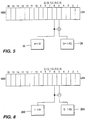
- a conventional spreading sequence is a pseudo-random digital sequence as shown in Figure 3 .
- the sequence is used to spread the signal being transmitted and to despread the signal being received.
- Two different binary codes using two different LFSR circuits provide I and Q channels for transmission of data. However, if there is high crosscorrelation between the I and Q channels at the receiver side, a great deal of noise will be output by the receiver.
- the ideal power spectrum is flat, where the average power is distributed over all frequency bins equally. This results in a narrow autocorrelation. All of the
- Equation (6) This equation is a modified version of Equation (6) and it performs the mapping of phase angles to one of four points for easy QPSK implementation. It limits the phases to the set ⁇ 0, ⁇ /2, ⁇ , 3 ⁇ /2 ⁇ .
- Figure 6 is a flow diagram of the method performed by the circuit shown in Figure 4 .
- the initial parameters M and N are loaded into registers or memory (not shown) before performing the dividing function (M divided by N).
- the value in accumulator 31 is preferably equal to zero.
- the remaining apparatus in the code generator 30 is also initialized ( S1 ) .
- the sum, which initially is zero, is added to the quotient of M/N ( S2 ).
- the fifth and sixth bits of the new sum are extracted ( S3 ) in order to be converted into the I and Q values ( S4 and S5 ) .
- the bits (L-2) and (L-3) should be mapped to QPSK constellation as follows:
- Figure 7 shows a second embodiment of the code generator 200 .
- Code generator 200 is substituted for code generator 30 and generates four-phase pseudo-random code sequences similar to those generated by the code generator 200 which greatly improve auto correlation properties and cross correlation properties.
- the second embodiment is an example of the second suboptimum implementation of Equation (11).
- four-phase sequences of any length can be generated, a length of 127 bits is selected as an example.
- a number M is selected to be relatively prime to N.
- the output of flip flops 220 1 through 220 L are transmitted to flip flops 230 1 through 230 L as well as mixer 240 .
- the mixer 240 also receives the output of flip flops 230 1 through 230 L .
- the accumulator 210 and flip flops 220 1 - 220 L , flip flops 230 1 - 230 L , and mixer 240 provide a flip flop feedback circuit.
- the output of mixer 240 is input to mixer 250 .
- Mixer 250 also receives an 8 bit input from (M/N).
- the extractor 260 extracts the fifth and sixth least significant bits from the mixer 250 .
- the sixth least significant bit output from extractor 260 is converted to an I value by converter 280 .
- Figure 9 is a flow diagram of the method performed by the circuit shown in Figure 7 .
- the initial parameters M and N are loaded into registers or memory (not shown) before performing the dividing function (M/N).
- the value k is preferably equal to zero.
- the remaining apparatus in the second embodiment of the code generator 200 is also initialized ( S1 ).
- the value of (M/N)k(k+1) is calculated ( S2 ).
- the fifth and sixth bits resulting from the above calculation are extracted ( S3 ) in order to be converted into I and Q values ( S4 and S5 ).
- the bits (L-2) and (L-3) should be mapped to QPSK constellation as follows:
Abstract
and means for converting the extracted first bit and second bit to I and Q values.

Description
- The present invention generally relates to an improved sequence design for code-division multiple access (CDMA) communications. More particularly, the invention is directed to generating complex four-phase pseudo-random code sequences which may be directly mapped to a quadrature phase shift keying (QPSK) signal constellation.
- Code-division multiple access (CDMA) is a type of spread spectrum communication system wherein each subscriber unit is distinguished from all other subscriber units by the possession of a unique code. In order to communicate with a particular subscriber unit, a transmitting unit imprints the unique code upon a transmission and the receiving unit uses the code to decode the transmission. CDMA communication systems transmit voice and data information using signals that appear noiselike and random. Since the random sequences are generated by standard deterministic logic elements, the generation of the bit sequences are predictable and repeatable. It is the use of these repeatable binary random sequences that permits easy modulation of any information-bearing digital signal for data communications. These predictable random sequences are called pseudo-random sequences.
- Each subscriber unit in a CDMA communication system receives a plurality of pseudo-random sequences from base stations which are within the communicating range of the subscriber unit. As indicated above, the receiving unit uses a particular pseudo-random code to attempt to decode one of the received pseudo-random sequences. The particular code can only be used to decode one pseudo-random sequence, the other received pseudo-random sequences contribute to noise.
- As the correlation between the pseudo-random sequences used by the CDMA communication system decreases, the amount of noise output by the receiving unit also decreases. This decrease can be explained as follows: There is a high correlation between the one pseudo-random sequence including the data to be transmitted to the subscriber unit and the pseudo-random sequence generated by the receiver. As the correlation between the one pseudo-random sequence and the other pseudo-random sequences decreases (i.e. cross correlation), it becomes easier for the subscriber unit to recognize its particular pseudo-random sequence and filter out all of the other pseudo-random sequences. Thus, noise is reduced and signal clarity enhanced.
- There is a need for an improved pseudo-random sequence generator which generates sequences having improved cross correlation properties to reduce the noise experienced by the receiver. There is also a need for a pseudo-random code generator that is easy to implement.
- The present invention provides an improved method and apparatus for generating complex four-phase pseudo-random code sequences, which can easily be mapped to a QPSK signal constellation and which have a low cross correlation and low out-of-phase autocorrelation.
- In one embodiment, a pseudo-random code generator produces complex four-phase CDMA codes utilizing an accumulator and a plurality of flip flops. The accumulator receives a quotient of a parameter M divided by a parameter N and receives feedback from the plurality of flip flops. The parameter M and N are integers, wherein M is relatively prime to N. The accumulator combines the quotient with the data received from the flip flops and transmits the combined data to the flip flops. Two bits are extracted and used to produce I and Q codes.
- In another embodiment, a pseudo-random code generator produces complex four-phase CDMA codes by providing a circuit for outputting an arithmetic progression of values and an incremental value of the arithmetic progression of values. The pseudo-random code generator also contains a first mixer for receiving the arithmetic progression of values and the incremental values. A second mixer receives the output of the first mixer and combines this output with the quotient of a parameter 2M divided by parameter N, wherein M and N are integers and M is relatively prime to N. Two bits are extracted from the second mixer and are converted into I and Q codes.
- Other advantages will become apparent to those skilled in the art after reading the detailed description of the preferred embodiments.
-
- Figure 1 is a block diagram of a spread spectrum transmitter of the present invention;
- Figure 2 is a block diagram of a spread spectrum receiver of the present invention;
- Figure 3 is a timing diagram of a conventional pseudo-random code sequence;
- Figure 4 is a first embodiment of a spread spectrum code generator for generating four-phase sequences according to the present invention;
- Figure 5 is a diagram showing the conversion to I and Q in the first embodiment of the spread spectrum code generator;
- Figure 6 is a diagram showing the method steps for generating four-phase sequences according to the first embodiment of the present invention;
- Figure 7 is a second embodiment of a spread spectrum code generator for generating four-phase sequences according to the present invention;
- Figure 8 is a diagram showing the conversion to I and Q in the second embodiment of the spread spectrum code generator;
- Figure 9 is a diagram showing the method steps for generating four-phase sequences according to the second embodiment of the present invention;
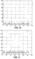
- Figure 10 is a graph of an example of an autocorrelation function for the first suboptimum implementation.
- Figure 11 is an example of a crosscorrelation function for the first suboptimum implementation.
-
- The preferred embodiments are described with reference to drawing figures wherein like numerals represent like elements throughout.
- A spread spectrum transmitter 10, as shown in Figure 1, includes an analog-to-digital (A/D) converter 12 for receiving a voice signal. A switch 14 receives both the digital voice signal from the A/D converter 12 and a digital data signal from a terminal (not shown). The switch 14 connects the spread spectrum transmitter 10 with an input for either digital voice signal or digital data. The digital voice signal and digital data are hereafter collectively referred to as digital data. The switch 14 directs the digital data to a spreader 20, which may comprise a mixer. A pseudo-random sequence generated by code generator 30 is applied to the spreader 20. The code generator 30 and the spreader 20 are shown as being contained within spread spectrum encoder 40.
- The spreader 20 performs a frequency spectrum spreading function by multiplying the digital data by the pseudo-random sequence in the time domain, which is equivalent to convolving the bimodal spectrum of the digital data with the approximately rectangular spectrum of the pseudo-random sequence in the frequency domain. The output of the spreader 20 is applied to a low-pass filter 50, whose cutoff frequency is equal to the system chip rate, Fcr. The output of the low-pass filter 50 is then applied to one terminal of a mixer 60 and upconverted, as determined by the carrier frequency Fc which is applied to its other terminal. The upconverted signal is then passed through a band-pass filter 70, which may be a helical resonator. The filter 70 has a bandwidth equal to twice the chip rate and a center frequency equal to the center frequency of the bandwidth of the spread spectrum system. The output of the filter 70 is applied to the input of an RF amplifier 80, whose output drives an antenna 90.
- A spread spectrum receiver 100 is shown in Figure 2. An antenna 110 receives the transmitted spread spectrum signal, which is filtered by a bandpass filter 120. The filter has a bandwidth equal to twice the chip rate Fcr, and a center frequency equal to the center frequency of the bandwidth of the spread spectrum system. The output of the filter 120 is subsequently downconverted by a mixer 130, possibly in two stages, to a baseband signal using a local oscillator having a constant frequency which is approximately the same as the carrier frequency Fc of the transmitter 10. The output of the mixer 130 is then despread by applying it to a first terminal of the despreader 140 while applying the same pseudo-random sequence as delivered to the spreader 20 to a second terminal of the despreader 140. The pseudo-random sequence is generated by a code generator 30. The despreader 140 and the code generator 30 are contained within a spread spectrum decoder 160 as shown in Figure 2. The output of the despreader 140 is applied to a low pass filter 180, which has a cutoff frequency at the data rate of the data input to the spread spectrum transmitter 10. The output of the low-pass filter 180 is a replica of the data input to Figure 1.
- It should be appreciated by those of skill in the art that the pseudo-random sequence used in the receiver 100 of a spread spectrum communication system must be synchronized with the pseudo-random sequence used in the transmitter 10. Methods for achieving this synchronization are also well known.
- A conventional spreading sequence is a pseudo-random digital sequence as shown in Figure 3. The sequence is used to spread the signal being transmitted and to despread the signal being received. Two different binary codes using two different LFSR circuits provide I and Q channels for transmission of data. However, if there is high crosscorrelation between the I and Q channels at the receiver side, a great deal of noise will be output by the receiver.
- The code generator 30 of the present invention generates pseudo-random code sequences with greatly enhanced crosscorrelation properties compared with the prior art pseudo-random sequences such as the one shown in Figure 3. A prior art pseudo-random sequence essentially comprises a signal having different frequency components. This signal is a combination of sinusoidal waveforms having different frequencies; both high frequency sinusoidal waveforms and low frequency sinusoidal waveforms. Thus, the signal has a frequency spectrum which can be divided into frequency where c k is the strength of the sinusoids at one of the discrete Fourier series representations or the strength of the sinusoids in the region or bin. The average power in s(t) is written as follows:The magnitude spectrum of s(t) is |ck| and power spectrum is |ck|2. The ideal power spectrum is flat, where the average power is distributed over all frequency bins equally. This results in a narrow autocorrelation. All of the |ck|2 should be equal. To obtain this, the instantaneous frequency is:

- The primary constraint is that the phase of the complex spreading sequence should be limited to {0, π/2, π, 3π/2}. This limitation leads to sudden phase changes and prevents the power spectrum from becoming completely flat. However, a sequence with relatively flat power spectral density can be obtained. For the phase to be continuous at t = (k/N)T, the recursive equation is
- The suboptimum implementation of the above equation when Θk is limited to {0,π/2,π,3π/2} is as follows:
- Continuing the sequential phase deviation to develop asecond suboptimum implementation, one has:

- Examining Equation 6 one sees that each phase term can be obtained by adding a variable term (2 π/N)( Mk) to the previous phase. Furthermore, since 2πk is equal to zero modulo 2π, the term one needs to add each phase to find the next phase reduces to (M/N), which is not an integer. Therefore, a possible implementation can be a recursive adder (accumulator) which adds the term (M/N) to the phase in each iteration.
- Figure 4 shows a first embodiment of the code generator 30 for generating four-phase pseudo-random code sequences which greatly improve autocorrelation properties and cross correlation properties. The first embodiment is an example of the first suboptimum implementation of Equation 7. Although four-phase sequences of any length can be generated, a length of 127 bits is selected as an example. Further, for the purposes of this example, there are N number of chips in a symbol, which represents the processing gain. A number M is selected to be relatively prime to N, which means that M and N do not have a common factor. The number of bits L required to provide a binary representation of the processing gain N is determined by solving the following equation:
- The code generator 30 includes an accumulator 31 which is 2L bits in length. Since N=127 in this example, L=8. Therefore, accumulator 31 has a length of 16 bits. An eight bit number M/N is applied to one input of the accumulator 31. A sixteen bit number from flip flops 32 1 through 32 2L is applied to a second input for the accumulator 31. Flip flops 321 through 322L may be replaced by a shift register. Although bits are input to flip flops 321 -322L and to accumulator 31 in parallel, the bits could also be input in series. The sum of the two numbers input into the accumulator 31 is transmitted to flip flops 321 through 322L . An extractor 33 extracts the fifth and sixth least significant bits from the flip flops 32 1 through 322L (Figure 5). The fifth and sixth least significant bits are applied to an exclusive-or gate 34.
- The output of the exclusive-or gate 34 is converted to a Q value by a converter 36. The sixth bit output from extractor 33 is converted to an I value by converter 35. The I and Q values output from converters 35 and 36 are applied to spreader 20 or despreader 140. As indicated before, M/N is an eight bit number in this example. The fifth and sixth bits of the accumulator output represent the first two significant bits of 4 (M/N) which appears in Equation (7). When 4 (M/N) is mapped to one of four values {0, 1,2, 3} by taking modulo 4, the result is the first two significant bits of 4(M/N), or equivalently fifth and sixth bits of the accumulator.
- Figure 6 is a flow diagram of the method performed by the circuit shown in Figure 4. The initial parameters M and N are loaded into registers or memory (not shown) before performing the dividing function (M divided by N). In addition, the value in accumulator 31 is preferably equal to zero. The remaining apparatus in the code generator 30 is also initialized (S1) . The sum, which initially is zero, is added to the quotient of M/N (S2). The fifth and sixth bits of the new sum are extracted (S3) in order to be converted into the I and Q values (S4 and S5) . The bits (L-2) and (L-3) should be mapped to QPSK constellation as follows:
- 00→11
- 01→1-1
- 10→-1-1
- 11→-11 This mapping can be done in software or hardware by using first:
-
- For example, if the sixth bit for L-2 bit is equal to zero, then the I value is one. If the sixth bit is a one, then the I value is negative one. In the case of the Q value, if the output of exclusive-or gate 34 is a zero, the Q value is one. If the output of exclusive-or gate 34 is a one, the Q value is negative one. The I and Q values are output to the spreader 20 or despreader 140 (S6). Method steps S2 through S6 are repeated until all the digital data supplied by switch 14 is transmitted or all the data is received by switch 190.
- Figure 7 shows a second embodiment of the code generator 200. Code generator 200 is substituted for code generator 30 and generates four-phase pseudo-random code sequences similar to those generated by the code generator 200 which greatly improve auto correlation properties and cross correlation properties. The second embodiment is an example of the second suboptimum implementation of Equation (11). Although four-phase sequences of any length can be generated, a length of 127 bits is selected as an example. Further, for the purposes of this example, there are N number of chips in a symbol, which represents the processing gain. A number M is selected to be relatively prime to N. The number of bits L required to provide a binary representation of processing gain N is determined by solving Equation (12). Since M=127 in this example, L=8. Therefore (M/N) is sixteen bits in length.
- The code generator 30 includes an accumulator 210 which is L bits in length. Accumulator 210 has a length of 8 bits. A "1" is preferably applied to one input of accumulator 210. The number from flip flops 2201 through 220L is applied to a second input of the accumulator 210. Flip flops 2201 through 220L may be replaced by a shift register. Although bits are input to flip flops 2201 through 220L and accumulator 210 in parallel, the bits could be input in series. The sum of the two numbers input into the accumulator 210 is transmitted to flip flops 2201 through 220L . The output of flip flops 220 1 through 220L are transmitted to flip flops 2301 through 230L as well as mixer 240. The mixer 240 also receives the output of flip flops 2301 through 230L . The accumulator 210 and flip flops 2201 -220L , flip flops 2301 -230L , and mixer 240 provide a flip flop feedback circuit. The output of mixer 240 is input to mixer 250. Mixer 250 also receives an 8 bit input from (M/N). The extractor 260 extracts the fifth and sixth least significant bits from the mixer 250. The sixth least significant bit output from extractor 260 is converted to an I value by converter 280. The fifth and sixth least significant bits are applied to an exclusive-or gate 270. The output of the exclusive-or gate 270 is converted to a Q value by a converter 290 as shown in Figure 8. The I and Q values output from converters 280 and 290 are applied to spreader 20 or despreader 140. As indicated before, (M/N) is an eight bit number in this example. Flip flops 2201 through 2201 output the k value and flip flops 2301 through 230L output the k+1 value to the mixer 240. The mixer 250 receives the output of mixer 240 and the product of (M/N). When 2(M/N)k(k+1) is mapped to one of the four values {0, 1, 2, 3} by taking modulo 4, the result is the fifth and sixth bits from extractor 260 (Figure 8).
- Figure 9 is a flow diagram of the method performed by the circuit shown in Figure 7. The initial parameters M and N are loaded into registers or memory (not shown) before performing the dividing function (M/N). In addition, the value k is preferably equal to zero. The remaining apparatus in the second embodiment of the code generator 200 is also initialized (S1). The value of (M/N)k(k+1) is calculated (S2). The fifth and sixth bits resulting from the above calculation are extracted (S3) in order to be converted into I and Q values (S4 and S5). The bits (L-2) and (L-3) should be mapped to QPSK constellation as follows:
- 00→11
- 01→1-1
- 10→-1-1
- 11→-11 This mapping can be done in software or hardware by using first:
-
- For example, if the sixth bit for L-2 is equal to zero, then the I value is 1. If the sixth bit is a 1, then the I value is -1. In the case of the Q value, if the output of the exclusive-or gate 270 is a zero, the Q value is 1. If the output of the exclusive-or gate 270 is a 1, the Q value is -1. The I and Q values are output to the spreader 20 or the despreader 140 (S6). The k value is incremented. Method steps S2 through S7 are repeated into all the digital data supplied by switch 14 is transmitted where all the data is received by switch 190.
- Figure 10 shows an auto correlation function where N=127 and M=44, which is the result of using the first suboptimum implementation to generate the pseudo-random code.
- Figure 11 shows a cross correlation function where N=127 and M=44, which is the result of using the first suboptimum implementation to generate the pseudo-random code.
- The autocorrelation a(n) for the sequence s(k) is given as:where the indexes in parentheses are taken modulo N, and the crosscorrelation c(n) of two sequences s(k) and r(k) is given as:
 where again the index is taken modulo N. The first suboptimum implementation achieves the desirable result of making the magnitude of the crosscorrelation and autocorrelation (except for a(0)) small compared to N. Although the results of the example of the second suboptimum implementation are not shown, the results are similar. Equations 13 and 14 are well known to one having ordinary skill in the art.
- Although the invention has been described in part by making detailed reference to certain specific embodiments, such detail is intended to be instructive rather than restrictive. It will be appreciated by those skilled in the art that many variations may be made in a structure and mode of operation without departing from the spirit and scope of the invention as disclosed in the teachings herein.
-
- 1. An apparatus for generating complex four-phase code division multiple access
(CDMA) codes comprising:
- a plurality of flip flops, which are initially set to zero;
- an accumulator having a first input for receiving an output from said plurality of flip flops and a second input for receiving a quotient of a parameter M divided by a parameter N, wherein M and N are integers and wherein M is relatively prime to N;
- said accumulator combines data received via said first and second inputs and outputs the combined data to said flip flops;
- an extractor extracting a first bit and a second bit from the flip flops; and
- means for converting the extracted first bit and second bit to I and Q code.
- 2. The apparatus as in aspect 1 wherein the plurality of flip flops provide a feedback and the accumulator is an adder.
- 3. An apparatus as in aspect 1 wherein there are sixteen flip flops representing progressively more specific bits, said first extracted bit is the fifth least significant bit, and wherein said second extracted bit is the sixth least significant bit.
- 4. The apparatus as in aspect 1 wherein the I and Q code is transmitted to a spreader.
- 5. The apparatus as in aspect 1 wherein the I and Q code is transmitted to a despreader.
- 6. A method for generating complex four-phase code division multiple access
(CDMA) codes comprising:
- (a) providing a register having a plurality of bits initially set to zero;
- (b) selecting a first parameter M and a second parameter N wherein M and N are integers and M is relatively prime to N;
- (c) combining the quotient M/N with the content of the register to produce a bit combination;
- (d) replacing the content of the register with the bit combination;
- (e) extracting first and second bits from the register;
- (f) generating I and Q code from the first and second extracted bits;
- (g) outputting the I and Q code; and
- (h) repeating steps (c) through (g).
- 7. The method as in aspect 6 wherein the register has sixteen bits of progressively more significance and the first bit is the fifth least significant bit from the sum, and wherein the second bit is the sixth least significant bit from the sum.
- 8. The method as in aspect 6, wherein the combining is performed by an adder which outputs the sum of the quotient of M/N and the content of the register.
- 9. The method as in aspect 6, wherein the I and Q code is output to a spreader.
- 10. The method as in aspect 6 wherein the I and Q code is output to a despreader.
- 11. An apparatus for generating complex four-phase code division multiple access
(CDMA) codes comprising:
- means for outputting an arithmetic progression of values;
- means for outputting an incremental value of said arithmetic progression of values;
- a first mixer having a first input for receiving said arithmetic progression of values and a second input for receiving said incremental values;
- a second mixer having a joint input receiving an output of said first mixer and a second input receiving the quotient of a parameter M divided by a parameter N, wherein M and N are integers and wherein M is relatively prime to N;
- an extractor associated with the output of said second mixer for extracting a first bit and a second bit from the second mixer; and
- means for converting the extracted first and second bits to I and Q code.
- 12. The apparatus of aspect 10 wherein said means for outputting an arithmetic progression of values and said means for outputting an incremental value of said arithmetic progression of values include at least one shift register.
- 13. The apparatus as in aspect 10, wherein the first bit is the fifth least significant bit of the second mixer and the second bit is the sixth least significant bit of the second mixer.
- 14. The apparatus as in aspect 10 wherein the I and Q codes are output to a spreader.
- 15. The apparatus as in aspect 10 wherein the I and Q codes are output to a despreader.
- 16. A method for generating four-phase code division multiple access (CDMA)
codes comprising:
- (a) selecting a parameter M and a processing gain N wherein M and N are integers and M is relatively prime to N;
- (b) dividing a processing gain N by M to provide a quotient;
- (c) mixing the quotient with an arithmetic progression of values and an incremental value of said arithmetic progression of values to provide a result;
- (d) extracting first and second bits from the result;
- (e) generating I and Q data from the extracted first and second bits;
- (f) outputting the I and Q data; and
- (g) repeating steps (c) through (f).
- 17. The method as in aspect 15, wherein the first bit is the fifth least significant bit from the mixer, and wherein the second bit is the sixth least significant bit from the mixer.
- 18. The method as in aspect 15, wherein the I and Q data is output to a spreader.
- 19. The method as in aspect 15, wherein the I and Q data is output to a despreader.
-
| (L-2) | (L-3) | (L-2) | (L-2)⊕(L-3) | |
| 0 | 0 | → | 0 | 0 |
| 0 | 1 | → | 0 | 1 |
| 1 | 0 | → | 1 | 1 |
| 1 | 1 | → | 1 | 0 |
| (L-2) | (L-3) | (L-2) | (L-2)⊕(L-3) | |
| 0 | 0 | → | 0 | 0 |
| 0 | 1 | → | 0 | 1 |
| 1 | 0 | → | 1 | 1 |
| 1 | 1 | → | 1 | 0 |
Claims (26)
- A spread spectrum transmitter comprising a spread spectrum encoder for encoding digital data to produce a spread spectrum signal and means for transmitting said signal, characterized in that the spread spectrum encoder includes a code generator incorporating an apparatus for generating complex four-phase code division multiple access (CDMA) codes, the apparatus comprising:an extractor extracting a first bit and a second bit from the flip flops; and means for converting the extracted first bit and second bit to I and Q values.a plurality of flip flops,an accumulator having a first input for receiving an output from said plurality of flip flops and a second input for receiving a quotient of a parameter M divided by a parameter N, wherein M and N are integers and wherein M is relatively prime to N; said accumulator combines data received via said first and second inputs and outputs the combined data to said flip flops;
- The transmitter of claim 1 wherein the plurality of flip flops provide a feedback and the accumulator is an adder.
- The transmitter of claim 1 wherein there are sixteen flip flops representing progressively more specific bits, said first extracted bit is the fifth least significant bit, and wherein said second extracted bit is the sixth least significant bit.
- The transmitter of claim 1 wherein there are 2L flip flops, wherein N ≤ 2L
- A method for transmitting a spread spectrum signal comprising the steps of encoding digital data to produce a spread spectrum signal and transmitting said signal, characterized in that the step of encoding includes generating complex four-phase code division multiple access (CDMA) codes by:(a) providing a register having a plurality of bits;(b) selecting a first parameter M and a second parameter N wherein M and N are integers and M is relatively prime to N;(c) combining the quotient M/N with the content of the register to produce a bit combination;(d) replacing the content of the register with the bit combination;(e) extracting first and second bits from the register;(f) generating I and Q values from the first and second extracted bits;(g) outputting the I and Q values; and(h) repeating steps (c) through (g).
- The method of claim 5 wherein the register has sixteen bits of progressively more significance and the first bit is the fifth least significant bit from the sum, and wherein the second bit is the sixth least significant bit from the sum.
- The method of claim 5, wherein the combining is performed by an adder which outputs the sum of the quotient of M/N and the content of the register.
- A spread spectrum transmitter comprising a spread spectrum encoder for encoding digital data to produce a spread spectrum signal and means for transmitting said signal, characterized in that the spread spectrum encoder includes a code generator incorporating an apparatus for generating complex four-phase code division multiple access (CDMA) codes comprising:wherein M and N are integers and wherein M is relatively prime to N;means for outputting an arithmetic progression of values;means for outputting an incremental value of said arithmetic progression of values;a first mixer having a first input for receiving said arithmetic progression of valuesand a second input for receiving said incremental values;a second mixer having a joint input receiving an output of said first mixer and asecond input receiving the quotient of a parameter M divided by a parameter N,an extractor associated with the output of said second mixer for extracting a first bitand a second bit from the second mixer; andmeans for converting the extracted first and second bits to I and Q values.
- The transmitter of claim 8 wherein said means for outputting an arithmetic progression of values and said means for outputting an incremental value of said arithmetic progression of values include at least one shift register.
- The transmitter of claim 8, wherein the first bit is the fifth least significant bit of the second mixer and the second bit is the sixth least significant bit of the second mixer.
- A method for transmitting a spread spectrum signal comprising the steps of encoding digital data to produce a spread spectrum signal and transmitting said signal, characterized in that the step of encoding includes generating four-phase code division multiple access (CDMA) codes by:(a) selecting a parameter M and a parameter N wherein M and N are integers and M is relatively prime to N;(b) dividing the parameter M by the parameter N to provide a quotient;(c) mixing the quotient with an arithmetic progression of values and an incremental value of said arithmetic progression of values to provide a result;(d) extracting first and second bits from the result;(e) generating I and Q values from the extracted first and second bits;(f) outputting the I and Q values; and(g) repeating steps (c) through (f).
- The method of claim 11, wherein the first bit is the fifth least significant bit from the mixer, and wherein the second bit is the sixth least significant bit from the mixer.
- A spread spectrum receiver comprising a transmitted spread spectrum signal receiver and a despreader for despreading a received spread spectrum signal to generate a replica of a transmitted digital data signal, characterized in that the despreader includes a code generator incorporating an apparatus for generating complex four-phase code division multiple access (CDMA) codes, the apparatus comprising:means for converting the extracted first bit and second bit to I and Q values.a plurality of flip flops,an accumulator having a first input for receiving an output from said plurality of flip flops and a second input for receiving a quotient of a parameter M divided by a parameter N, wherein M and N are integers and wherein M is relatively prime to N; said accumulator combines data received via said first and second inputs and outputs the combined data to said flip flops; an extractor extracting a first bit and a second bit from the flip flops; and
- The receiver of claim 13 wherein the plurality of flip flops provide a feedback and the accumulator is an adder.
- The receiver of claim 13 wherein there are sixteen flip flops representing progressively more specific bits, said first extracted bit is the fifth least significant bit, and wherein said second extracted bit is the sixth least significant bit.
- The receiver of claim 13 wherein there are 2L flip flops, wherein N ≤ 2L
- A method for receiving a spread spectrum signal comprising the steps of receiving
a transmitted spread spectrum signal and despreading said signal, characterized in that the step of despreading includes generating complex four-phase code division multiple access (CDMA) codes by:(a) providing a register having a plurality of bits;(b) selecting a first parameter M and a second parameter N wherein M and N are integers and M is relatively prime to N;(c) combining the quotient M/N with the content of the register to produce a bit combination;(d) replacing the content of the register with the bit combination;(e) extracting first and second bits from the register;(f) generating I and Q values from the first and second extracted bits;(g) outputting the I and Q values; and(h) repeating steps (c) through (g). - The method of claim 17 wherein the register has sixteen bits of progressively more significance and the first bit is the fifth least significant bit from the sum, and wherein the second bit is the sixth least significant bit from the sum.
- The method of claim 17, wherein the combining is performed by an adder which outputs the sum of the quotient of M/N and the content of the register.
- A spread spectrum receiver comprising a transmitted spread spectrum signal receiver and a despreader for despreading a received spread spectrum signal to generate a replica of a transmitted digital data signal, characterized in that the despreader includes a code generator incorporating an apparatus for generating complex four-phase code division multiple access (CDMA) codes comprising:wherein M and N are integers and wherein M is relatively prime to N;means for outputting an arithmetic progression of values;means for outputting an incremental value of said arithmetic progression of values;a first mixer having a first input for receiving said arithmetic progression of valuesand a second input for receiving said incremental values;a second mixer having a joint input receiving an output of said first mixer and a second input receiving the quotient of a parameter M divided by a parameter N,an extractor associated with the output of said second mixer for extracting a first bit and a second bit from the second mixer; andmeans for converting the extracted first and second bits to I and Q values.
- The receiver of claim 18 wherein said means for outputting an arithmetic progression of values and said means for outputting an incremental value of said arithmetic progression of values include at least one shift register.
- The receiver of claim 18, wherein the first bit is the fifth least significant bit of the second mixer and the second bit is the sixth least significant bit of the second mixer.
- A method for receiving a spread spectrum signal comprising the steps of receiving a transmitted spread spectrum signal and despreading said signal, characterized in that the step of despreading includes generating four-phase code division multiple access (CDMA) codes by:(a) selecting a parameter M and a parameter N wherein M and N are integers and M is relatively prime to N;(b) dividing the parameter M by the parameter N to provide a quotient;(c) mixing the quotient with an arithmetic progression of values and an incremental value of said arithmetic progression of values to provide a result;(d) extracting first and second bits from the result;(e) generating I and Q values from the extracted first and second bits;(f) outputting the I and Q values; and(g) repeating steps (c) through (f).
- The method of claim 23, wherein the first bit is the fifth least significant bit from the mixer, and wherein the second bit is the sixth least significant bit from the mixer.
- An apparatus for generating complex four-phase code division multiple access (CDMA) codes, the apparatus comprising:a shift register,an accumulator having a first input for receiving an output from said shift register and a second input for receiving a quotient of a parameter M divided by a parameter N, wherein M and N are integers and wherein M is relatively prime to N; said accumulator combines data received via said first and second inputs and outputs the combined data to said shift register;
an extractor extracting a first bit and a second bit from the shift register; and means
for converting the extracted first bit and second bit to I and Q values. - The apparatus of claim 25 wherein the shift register has 2L bits where N ≤ 2L.
Applications Claiming Priority (3)
| Application Number | Priority Date | Filing Date | Title |
|---|---|---|---|
| US956808 | 1997-10-23 | ||
| US08/956,808 US6026117A (en) | 1997-10-23 | 1997-10-23 | Method and apparatus for generating complex four-phase sequences for a CDMA communication system |
| EP98922420A EP0965188B9 (en) | 1997-10-23 | 1998-05-20 | Method and apparatus for generating complex four-phase sequences for a cdma communication system |
Related Parent Applications (1)
| Application Number | Title | Priority Date | Filing Date |
|---|---|---|---|
| EP98922420A Division EP0965188B9 (en) | 1997-10-23 | 1998-05-20 | Method and apparatus for generating complex four-phase sequences for a cdma communication system |
Publications (2)
| Publication Number | Publication Date |
|---|---|
| EP1489761A1 true EP1489761A1 (en) | 2004-12-22 |
| EP1489761B1 EP1489761B1 (en) | 2007-03-28 |
Family
ID=25498721
Family Applications (2)
| Application Number | Title | Priority Date | Filing Date |
|---|---|---|---|
| EP04018352A Expired - Lifetime EP1489761B1 (en) | 1997-10-23 | 1998-05-20 | Method and apparatus for generating complex four-phase sequences for a cdma communication system |
| EP98922420A Expired - Lifetime EP0965188B9 (en) | 1997-10-23 | 1998-05-20 | Method and apparatus for generating complex four-phase sequences for a cdma communication system |
Family Applications After (1)
| Application Number | Title | Priority Date | Filing Date |
|---|---|---|---|
| EP98922420A Expired - Lifetime EP0965188B9 (en) | 1997-10-23 | 1998-05-20 | Method and apparatus for generating complex four-phase sequences for a cdma communication system |
Country Status (13)
| Country | Link |
|---|---|
| US (8) | US6026117A (en) |
| EP (2) | EP1489761B1 (en) |
| JP (1) | JP3884776B2 (en) |
| KR (1) | KR100545502B1 (en) |
| CN (2) | CN1496045A (en) |
| AT (2) | ATE358364T1 (en) |
| AU (1) | AU7497398A (en) |
| CA (1) | CA2272864C (en) |
| DE (3) | DE69825427T2 (en) |
| DK (1) | DK0965188T3 (en) |
| ES (2) | ES2282768T3 (en) |
| HK (1) | HK1025690A1 (en) |
| WO (1) | WO1999021299A1 (en) |
Families Citing this family (24)
| Publication number | Priority date | Publication date | Assignee | Title |
|---|---|---|---|---|
| US6385264B1 (en) * | 1999-06-08 | 2002-05-07 | Qualcomm Incorporated | Method and apparatus for mitigating interference between base stations in a wideband CDMA system |
| KR100404180B1 (en) * | 1999-07-06 | 2003-11-03 | 엘지전자 주식회사 | Base Station Signal Demodulation Device in Communication System |
| WO2001055866A1 (en) * | 2000-01-28 | 2001-08-02 | Morphics Technolgoy Inc. | A wireless spread spectrum communication platform using dynamically reconfigurable logic |
| WO2001067605A1 (en) * | 2000-03-09 | 2001-09-13 | Fujitsu Limited | Method and apparatus for producing pseudorandom signal |
| DE10036372A1 (en) * | 2000-07-18 | 2002-01-31 | Univ Berlin Tech | Transmitter for transmitter/receiver arrangement has encoding arrangement between data converter and data output for converting data of first type into coded data of same data type |
| GB2376157B (en) * | 2001-01-29 | 2003-12-10 | Morphics Tech Inc | A method of generating a configuration for a configurable spread spectrum communication device |
| US7203474B2 (en) * | 2001-10-24 | 2007-04-10 | Rohm Co., Ltd. | Receiver system |
| AU2002250774A1 (en) * | 2002-03-22 | 2003-10-08 | Linkair Communications, Inc. | A coding method to create general spread spectrum sequence with zero correlation window |
| JP4571178B2 (en) * | 2002-11-12 | 2010-10-27 | 株式会社リコー | Ultra-wideband communication receiver, reproduction data generation method for ultra-wideband communication, and ultra-wideband communication system |
| JP4057467B2 (en) * | 2002-11-12 | 2008-03-05 | 株式会社リコー | Ultra-wideband communication receiver and reproduction data generation method for ultra-wideband communication |
| KR100511299B1 (en) | 2002-12-13 | 2005-08-31 | 엘지전자 주식회사 | Data symbol mapping and spreading apparatus for mobile communication system |
| EP1496371A1 (en) * | 2003-07-07 | 2005-01-12 | Mitsubishi Electric Information Technology Centre Europe B.V. | Generation of packets of waveforms |
| US20060013332A1 (en) * | 2004-07-16 | 2006-01-19 | Rayburn David C | Method of sending information using superresolution to didtinguish overlapping symbols |
| US8363704B1 (en) | 2003-07-24 | 2013-01-29 | Rayburn David C | Method of transmitting information using a bandwidth limited communications channel |
| US8391410B2 (en) | 2004-07-29 | 2013-03-05 | Qualcomm Incorporated | Methods and apparatus for configuring a pilot symbol in a wireless communication system |
| US20070081484A1 (en) * | 2004-07-29 | 2007-04-12 | Wang Michael M | Methods and apparatus for transmitting a frame structure in a wireless communication system |
| CA2575551A1 (en) * | 2004-07-29 | 2006-02-09 | Qualcomm Incorporated | System and method for interleaving |
| US20080317142A1 (en) * | 2005-07-29 | 2008-12-25 | Qualcomm Incorporated | System and method for frequency diversity |
| US9246728B2 (en) | 2004-07-29 | 2016-01-26 | Qualcomm Incorporated | System and method for frequency diversity |
| US9391751B2 (en) * | 2005-07-29 | 2016-07-12 | Qualcomm Incorporated | System and method for frequency diversity |
| US9042212B2 (en) | 2005-07-29 | 2015-05-26 | Qualcomm Incorporated | Method and apparatus for communicating network identifiers in a communication system |
| US7983945B2 (en) * | 2006-10-18 | 2011-07-19 | Vienna Human Capital Advisors, Llc | Method and system for analysis of financial investment in human capital resources |
| WO2012111256A1 (en) * | 2011-02-18 | 2012-08-23 | パナソニック株式会社 | Method of signal generation and signal generating device |
| EP2608474B1 (en) * | 2011-12-23 | 2018-09-05 | Vodafone Holding GmbH | Method and transmitter/receiver for data transmission with flexible exploitation of time and frequency diversity |
Citations (4)
| Publication number | Priority date | Publication date | Assignee | Title |
|---|---|---|---|---|
| US5218559A (en) * | 1991-01-16 | 1993-06-08 | France Telecom Etablissement Autonome De Droit Public (Centre National D'etudes Des Telecommunications) | Pseudo-random generator |
| US5416797A (en) * | 1990-06-25 | 1995-05-16 | Qualcomm Incorporated | System and method for generating signal waveforms in a CDMA cellular telephone system |
| US5471497A (en) * | 1993-11-01 | 1995-11-28 | Zehavi; Ephraim | Method and apparatus for variable rate signal transmission in a spread spectrum communication system using coset coding |
| US5497395A (en) * | 1994-04-04 | 1996-03-05 | Qualcomm Incorporated | Method and apparatus for modulating signal waveforms in a CDMA communication system |
Family Cites Families (21)
| Publication number | Priority date | Publication date | Assignee | Title |
|---|---|---|---|---|
| FR1580108A (en) * | 1966-03-02 | 1969-09-05 | ||
| US3648238A (en) * | 1970-05-15 | 1972-03-07 | Precision Instr Co | Error-correcting encoder and decoder for asymmetric binary data channels |
| US4158193A (en) * | 1977-06-06 | 1979-06-12 | International Data Sciences, Inc. | Data transmission test set with synchronization detector |
| FR2394921A1 (en) * | 1977-06-13 | 1979-01-12 | Poitevin Jean Pierre | FOUR-PHASE JUMP-SHIFT MODULATOR |
| US4755969A (en) * | 1986-11-07 | 1988-07-05 | Digital Electronic Communications Equipment (Dece Corp.) | Pseudo random sequence generation |
| US5361047A (en) * | 1990-02-13 | 1994-11-01 | Hitachi, Ltd. | PI/4 shift QPSK modulator and communication apparatus used therewith |
| US5187676A (en) * | 1991-06-28 | 1993-02-16 | Digital Equipment Corporation | High-speed pseudo-random number generator and method for generating same |
| US5233629A (en) * | 1991-07-26 | 1993-08-03 | General Instrument Corporation | Method and apparatus for communicating digital data using trellis coded qam |
| FI925870A (en) * | 1991-12-27 | 1993-06-28 | Mitsubishi Electric Corp | DEMODULATOR MED FOERDROEJD DETEKTERING |
| US5408628A (en) * | 1992-07-07 | 1995-04-18 | Odetics, Inc. | Solid state recorder with flexible width data bus utilizing lock mapping and error correction and detection circuits |
| US5373532A (en) * | 1992-09-11 | 1994-12-13 | Fujitsu Limited | π/4 quadrature phase shift keying modulator |
| US5488629A (en) * | 1993-02-17 | 1996-01-30 | Matsushita Electric Industrial Co., Ltd. | Signal processing circuit for spread spectrum communications |
| US5467294A (en) * | 1994-03-09 | 1995-11-14 | Hu; Vince | High speed, low power direct digital synthesizer |
| KR970002951B1 (en) * | 1994-04-13 | 1997-03-13 | 양승택 | Power-of-two length pseudorandom noise sequence generator |
| US5604770A (en) * | 1994-10-13 | 1997-02-18 | Hewlett-Packard Company | PI/4 DQPSK modulation with coarse mapper precession and fine filter precession |
| US5640416A (en) * | 1995-06-07 | 1997-06-17 | Comsat Corporation | Digital downconverter/despreader for direct sequence spread spectrum communications system |
| JP2737730B2 (en) * | 1995-11-30 | 1998-04-08 | 日本電気株式会社 | Spread spectrum transceiver |
| US6823488B1 (en) * | 1998-08-27 | 2004-11-23 | Texas Instruments Incorporated | Packet binary convolutional codes |
| US6201835B1 (en) * | 1999-03-05 | 2001-03-13 | Burr-Brown Corporation | Frequency-shaped pseudo-random chopper stabilization circuit and method for delta-sigma modulator |
| US6374278B1 (en) * | 1999-03-25 | 2002-04-16 | Intel Corporation | Method and apparatus for the generation of statistically random numbers |
| US6628727B1 (en) * | 2000-01-10 | 2003-09-30 | Syncomm Technology Corporation | Apparatus and method for performing π/4-DQPSK baseband modulation based on a signal mapping to be simplified |
-
1997
- 1997-10-23 US US08/956,808 patent/US6026117A/en not_active Expired - Lifetime
-
1998
- 1998-05-20 DE DE69825427T patent/DE69825427T2/en not_active Expired - Lifetime
- 1998-05-20 DK DK98922420T patent/DK0965188T3/en active
- 1998-05-20 KR KR1019997004487A patent/KR100545502B1/en not_active IP Right Cessation
- 1998-05-20 ES ES04018352T patent/ES2282768T3/en not_active Expired - Lifetime
- 1998-05-20 AU AU74973/98A patent/AU7497398A/en not_active Abandoned
- 1998-05-20 AT AT04018352T patent/ATE358364T1/en not_active IP Right Cessation
- 1998-05-20 CN CNA2003101044210A patent/CN1496045A/en active Pending
- 1998-05-20 CA CA002272864A patent/CA2272864C/en not_active Expired - Fee Related
- 1998-05-20 AT AT98922420T patent/ATE272917T1/en not_active IP Right Cessation
- 1998-05-20 EP EP04018352A patent/EP1489761B1/en not_active Expired - Lifetime
- 1998-05-20 CN CN98801378A patent/CN1131609C/en not_active Expired - Fee Related
- 1998-05-20 JP JP52396999A patent/JP3884776B2/en not_active Expired - Fee Related
- 1998-05-20 DE DE69837452T patent/DE69837452T2/en not_active Expired - Lifetime
- 1998-05-20 DE DE0965188T patent/DE965188T1/en active Pending
- 1998-05-20 ES ES98922420T patent/ES2138949T3/en not_active Expired - Lifetime
- 1998-05-20 WO PCT/US1998/010199 patent/WO1999021299A1/en active IP Right Grant
- 1998-05-20 EP EP98922420A patent/EP0965188B9/en not_active Expired - Lifetime
-
1999
- 1999-12-27 US US09/472,348 patent/US6337875B1/en not_active Expired - Lifetime
-
2000
- 2000-06-19 HK HK00103672A patent/HK1025690A1/en not_active IP Right Cessation
-
2001
- 2001-11-13 US US10/011,113 patent/US6606344B2/en not_active Expired - Fee Related
-
2002
- 2002-02-04 US US10/066,860 patent/US6614833B2/en not_active Expired - Fee Related
- 2002-02-04 US US10/067,082 patent/US6597726B2/en not_active Expired - Fee Related
- 2002-02-04 US US10/066,968 patent/US6731671B2/en not_active Expired - Fee Related
-
2003
- 2003-08-08 US US10/637,463 patent/US7164705B2/en not_active Expired - Fee Related
-
2004
- 2004-02-12 US US10/777,369 patent/US20050002443A1/en not_active Abandoned
Patent Citations (4)
| Publication number | Priority date | Publication date | Assignee | Title |
|---|---|---|---|---|
| US5416797A (en) * | 1990-06-25 | 1995-05-16 | Qualcomm Incorporated | System and method for generating signal waveforms in a CDMA cellular telephone system |
| US5218559A (en) * | 1991-01-16 | 1993-06-08 | France Telecom Etablissement Autonome De Droit Public (Centre National D'etudes Des Telecommunications) | Pseudo-random generator |
| US5471497A (en) * | 1993-11-01 | 1995-11-28 | Zehavi; Ephraim | Method and apparatus for variable rate signal transmission in a spread spectrum communication system using coset coding |
| US5497395A (en) * | 1994-04-04 | 1996-03-05 | Qualcomm Incorporated | Method and apparatus for modulating signal waveforms in a CDMA communication system |
Non-Patent Citations (1)
| Title |
|---|
| C. DOWNING: "PROPOSAL FOR A DIGITAL PSEUDORANDOM NUMBER GENERATOR", ELECTRONIC LETTERS, vol. 20, no. 11, 1 May 1984 (1984-05-01), london ,gb, pages 435 - 436, XP002075219 * |
Also Published As
Similar Documents
| Publication | Publication Date | Title |
|---|---|---|
| EP0965188B1 (en) | Method and apparatus for generating complex four-phase sequences for a cdma communication system | |
| RU2280957C2 (en) | Method, transmitter, and receiver for digital communications with expanded signal spectrum by way of modulation using complementary golay numbers | |
| RU2242819C2 (en) | Multiple access coding using convoluted sequences for mobile radio communication systems | |
| US7411997B2 (en) | Apparatus and method for filtering a spectrum spread communication | |
| Popovic | Spreading sequences for multicarrier CDMA systems | |
| KR100296563B1 (en) | Severe taxing for wireless communication | |
| JP4406401B2 (en) | Communication apparatus and communication method | |
| US7443906B1 (en) | Apparatus and method for modulating data message by employing orthogonal variable spreading factor (OVSF) codes in mobile communication system | |
| EP0782288B1 (en) | Spread spectrum communication system | |
| US6636549B1 (en) | Method for calculating phase shift coefficients of an M sequence | |
| Sarwate et al. | Partial correlation effects in direct-sequence spread-spectrum multiple-access communication systems | |
| JPH07107007A (en) | Spreading code generation system | |
| MXPA99004719A (en) | Method and apparatus for generating complex four-phase sequences for a cdma communication system | |
| Kraus et al. | Evaluation of a continuous valued chaotic spreader used in a Chaotic Digital Code-Division Multiple Access ((CD) 2 MA) system | |
| Massey et al. | Regenerative pseudo‐noise‐like (PNL) ranging sequences for deep‐space missions | |
| JPH09162846A (en) | Transmitting system by spread spectrum system | |
| JPH08307320A (en) | Radio communication equipment | |
| JPH08251138A (en) | Method and equipment for spread spectrum communication |
Legal Events
| Date | Code | Title | Description |
|---|---|---|---|
| PUAI | Public reference made under article 153(3) epc to a published international application that has entered the european phase |
Free format text: ORIGINAL CODE: 0009012 |
|
| 17P | Request for examination filed |
Effective date: 20040803 |
|
| AC | Divisional application: reference to earlier application |
Ref document number: 0965188 Country of ref document: EP Kind code of ref document: P |
|
| AK | Designated contracting states |
Kind code of ref document: A1 Designated state(s): AT BE CH DE DK ES FI FR GB GR IE IT LI LU MC NL PT SE |
|
| RIN1 | Information on inventor provided before grant (corrected) |
Inventor name: OZLUTURK, FATIH M. |
|
| AKX | Designation fees paid |
Designated state(s): AT BE CH DE DK ES FI FR GB GR IE IT LI LU MC NL PT SE |
|
| REG | Reference to a national code |
Ref country code: HK Ref legal event code: DE Ref document number: 1074121 Country of ref document: HK |
|
| GRAP | Despatch of communication of intention to grant a patent |
Free format text: ORIGINAL CODE: EPIDOSNIGR1 |
|
| RAP1 | Party data changed (applicant data changed or rights of an application transferred) |
Owner name: INTERDIGITAL TECHNOLOGY CORPORATION |
|
| GRAS | Grant fee paid |
Free format text: ORIGINAL CODE: EPIDOSNIGR3 |
|
| GRAA | (expected) grant |
Free format text: ORIGINAL CODE: 0009210 |
|
| AC | Divisional application: reference to earlier application |
Ref document number: 0965188 Country of ref document: EP Kind code of ref document: P |
|
| AK | Designated contracting states |
Kind code of ref document: B1 Designated state(s): AT BE CH DE DK ES FI FR GB GR IE IT LI LU MC NL PT SE |
|
| PG25 | Lapsed in a contracting state [announced via postgrant information from national office to epo] |
Ref country code: CH Free format text: LAPSE BECAUSE OF FAILURE TO SUBMIT A TRANSLATION OF THE DESCRIPTION OR TO PAY THE FEE WITHIN THE PRESCRIBED TIME-LIMIT Effective date: 20070328 Ref country code: NL Free format text: LAPSE BECAUSE OF FAILURE TO SUBMIT A TRANSLATION OF THE DESCRIPTION OR TO PAY THE FEE WITHIN THE PRESCRIBED TIME-LIMIT Effective date: 20070328 Ref country code: LI Free format text: LAPSE BECAUSE OF FAILURE TO SUBMIT A TRANSLATION OF THE DESCRIPTION OR TO PAY THE FEE WITHIN THE PRESCRIBED TIME-LIMIT Effective date: 20070328 Ref country code: AT Free format text: LAPSE BECAUSE OF FAILURE TO SUBMIT A TRANSLATION OF THE DESCRIPTION OR TO PAY THE FEE WITHIN THE PRESCRIBED TIME-LIMIT Effective date: 20070328 Ref country code: BE Free format text: LAPSE BECAUSE OF FAILURE TO SUBMIT A TRANSLATION OF THE DESCRIPTION OR TO PAY THE FEE WITHIN THE PRESCRIBED TIME-LIMIT Effective date: 20070328 |
|
| REG | Reference to a national code |
Ref country code: GB Ref legal event code: FG4D |
|
| REG | Reference to a national code |
Ref country code: CH Ref legal event code: EP |
|
| REF | Corresponds to: |
Ref document number: 69837452 Country of ref document: DE Date of ref document: 20070510 Kind code of ref document: P |
|
| REG | Reference to a national code |
Ref country code: IE Ref legal event code: FG4D |
|
| REG | Reference to a national code |
Ref country code: SE Ref legal event code: TRGR |
|
| PG25 | Lapsed in a contracting state [announced via postgrant information from national office to epo] |
Ref country code: PT Free format text: LAPSE BECAUSE OF FAILURE TO SUBMIT A TRANSLATION OF THE DESCRIPTION OR TO PAY THE FEE WITHIN THE PRESCRIBED TIME-LIMIT Effective date: 20070828 |
|
| ET | Fr: translation filed | ||
| REG | Reference to a national code |
Ref country code: CH Ref legal event code: PL |
|
| NLV1 | Nl: lapsed or annulled due to failure to fulfill the requirements of art. 29p and 29m of the patents act | ||
| REG | Reference to a national code |
Ref country code: ES Ref legal event code: FG2A Ref document number: 2282768 Country of ref document: ES Kind code of ref document: T3 |
|
| REG | Reference to a national code |
Ref country code: HK Ref legal event code: WD Ref document number: 1074121 Country of ref document: HK |
|
| PG25 | Lapsed in a contracting state [announced via postgrant information from national office to epo] |
Ref country code: MC Free format text: LAPSE BECAUSE OF NON-PAYMENT OF DUE FEES Effective date: 20070531 Ref country code: DK Free format text: LAPSE BECAUSE OF FAILURE TO SUBMIT A TRANSLATION OF THE DESCRIPTION OR TO PAY THE FEE WITHIN THE PRESCRIBED TIME-LIMIT Effective date: 20070328 |
|
| PLBE | No opposition filed within time limit |
Free format text: ORIGINAL CODE: 0009261 |
|
| STAA | Information on the status of an ep patent application or granted ep patent |
Free format text: STATUS: NO OPPOSITION FILED WITHIN TIME LIMIT |
|
| 26N | No opposition filed |
Effective date: 20080102 |
|
| PG25 | Lapsed in a contracting state [announced via postgrant information from national office to epo] |
Ref country code: IT Free format text: LAPSE BECAUSE OF NON-PAYMENT OF DUE FEES Effective date: 20070520 Ref country code: GR Free format text: LAPSE BECAUSE OF FAILURE TO SUBMIT A TRANSLATION OF THE DESCRIPTION OR TO PAY THE FEE WITHIN THE PRESCRIBED TIME-LIMIT Effective date: 20070629 |
|
| PG25 | Lapsed in a contracting state [announced via postgrant information from national office to epo] |
Ref country code: LU Free format text: LAPSE BECAUSE OF NON-PAYMENT OF DUE FEES Effective date: 20070520 |
|
| PGFP | Annual fee paid to national office [announced via postgrant information from national office to epo] |
Ref country code: GB Payment date: 20140514 Year of fee payment: 17 Ref country code: IE Payment date: 20140512 Year of fee payment: 17 |
|
| PGFP | Annual fee paid to national office [announced via postgrant information from national office to epo] |
Ref country code: FR Payment date: 20140509 Year of fee payment: 17 Ref country code: FI Payment date: 20140512 Year of fee payment: 17 Ref country code: ES Payment date: 20140411 Year of fee payment: 17 Ref country code: DE Payment date: 20140515 Year of fee payment: 17 Ref country code: SE Payment date: 20140513 Year of fee payment: 17 |
|
| REG | Reference to a national code |
Ref country code: DE Ref legal event code: R119 Ref document number: 69837452 Country of ref document: DE |
|
| GBPC | Gb: european patent ceased through non-payment of renewal fee |
Effective date: 20150520 |
|
| PG25 | Lapsed in a contracting state [announced via postgrant information from national office to epo] |
Ref country code: FI Free format text: LAPSE BECAUSE OF NON-PAYMENT OF DUE FEES Effective date: 20150520 |
|
| REG | Reference to a national code |
Ref country code: IE Ref legal event code: MM4A |
|
| REG | Reference to a national code |
Ref country code: FR Ref legal event code: ST Effective date: 20160129 |
|
| PG25 | Lapsed in a contracting state [announced via postgrant information from national office to epo] |
Ref country code: SE Free format text: LAPSE BECAUSE OF NON-PAYMENT OF DUE FEES Effective date: 20150521 |
|
| PG25 | Lapsed in a contracting state [announced via postgrant information from national office to epo] |
Ref country code: DE Free format text: LAPSE BECAUSE OF NON-PAYMENT OF DUE FEES Effective date: 20151201 Ref country code: GB Free format text: LAPSE BECAUSE OF NON-PAYMENT OF DUE FEES Effective date: 20150520 Ref country code: IE Free format text: LAPSE BECAUSE OF NON-PAYMENT OF DUE FEES Effective date: 20150520 |
|
| PG25 | Lapsed in a contracting state [announced via postgrant information from national office to epo] |
Ref country code: FR Free format text: LAPSE BECAUSE OF NON-PAYMENT OF DUE FEES Effective date: 20150601 |
|
| REG | Reference to a national code |
Ref country code: ES Ref legal event code: FD2A Effective date: 20160628 |
|
| PG25 | Lapsed in a contracting state [announced via postgrant information from national office to epo] |
Ref country code: ES Free format text: LAPSE BECAUSE OF NON-PAYMENT OF DUE FEES Effective date: 20150521 |