EP1515158A2 - Ultrasound imaging method combined with the presence of contrast media in the body under examination - Google Patents
Ultrasound imaging method combined with the presence of contrast media in the body under examination Download PDFInfo
- Publication number
- EP1515158A2 EP1515158A2 EP03425581A EP03425581A EP1515158A2 EP 1515158 A2 EP1515158 A2 EP 1515158A2 EP 03425581 A EP03425581 A EP 03425581A EP 03425581 A EP03425581 A EP 03425581A EP 1515158 A2 EP1515158 A2 EP 1515158A2
- Authority
- EP
- European Patent Office
- Prior art keywords
- frequency
- return signal
- fundamental
- subharmonic
- band
- Prior art date
- Legal status (The legal status is an assumption and is not a legal conclusion. Google has not performed a legal analysis and makes no representation as to the accuracy of the status listed.)
- Granted
Links
Images


Classifications
-
- A—HUMAN NECESSITIES
- A61—MEDICAL OR VETERINARY SCIENCE; HYGIENE
- A61B—DIAGNOSIS; SURGERY; IDENTIFICATION
- A61B8/00—Diagnosis using ultrasonic, sonic or infrasonic waves
- A61B8/48—Diagnostic techniques
- A61B8/481—Diagnostic techniques involving the use of contrast agent, e.g. microbubbles introduced into the bloodstream
-
- G—PHYSICS
- G01—MEASURING; TESTING
- G01S—RADIO DIRECTION-FINDING; RADIO NAVIGATION; DETERMINING DISTANCE OR VELOCITY BY USE OF RADIO WAVES; LOCATING OR PRESENCE-DETECTING BY USE OF THE REFLECTION OR RERADIATION OF RADIO WAVES; ANALOGOUS ARRANGEMENTS USING OTHER WAVES
- G01S7/00—Details of systems according to groups G01S13/00, G01S15/00, G01S17/00
- G01S7/52—Details of systems according to groups G01S13/00, G01S15/00, G01S17/00 of systems according to group G01S15/00
- G01S7/52017—Details of systems according to groups G01S13/00, G01S15/00, G01S17/00 of systems according to group G01S15/00 particularly adapted to short-range imaging
- G01S7/52023—Details of receivers
- G01S7/52036—Details of receivers using analysis of echo signal for target characterisation
- G01S7/52038—Details of receivers using analysis of echo signal for target characterisation involving non-linear properties of the propagation medium or of the reflective target
- G01S7/52039—Details of receivers using analysis of echo signal for target characterisation involving non-linear properties of the propagation medium or of the reflective target exploiting the non-linear response of a contrast enhancer, e.g. a contrast agent
Definitions
- the invention addresses an ultrasound imaging method combined with the presence of contrast agents in the body under examination, comprising the steps of:
- Static tissues typically have a good echogenicity and are optimally detectable by ultrasonic imaging at the fundamental frequency by using the so-called B-mode.
- B-mode images at the fundamental transmission frequency are high-quality images, as the transmit signal may consist of a broadband pulse, i.e. a very short pulse, which ensures an optimized resolution.
- the generated return signal not only contains a fundamental component, i.e. at the same frequency as the transmit beam, but also comprises nonlinear components, as components at the second or higher-order harmonics of the fundamental transmission frequency.
- US 6,066,098 teaches an ultrasonic imaging method which does not only use a certain frequency of the return signal, but acquires the whole spectrum of the received signal frequencies. As this spectrum is characteristic for each type of tissue, this method allows to identify the type of tissue that generated the reflected signal at a predetermined scanning depth and to differentiate tissue contributions from contrast agent contributions in the return signal.
- the excitation of the subharmonic components of the return signal generated by contrast agents requires the transmit pulses to be relatively long, and such time length of transmit pulses causes an image quality degradation in terms of resolution, presence of side lobes and generation of artifacts.
- contrast agent signals is not generally designed for B-mode imaging, hence to imaging in a narrow sense, but especially for detecting the presence of contrast agents and possibly the perfusion characteristics thereof, or for determining the speed or amount of flow.
- the invention has the object of providing a method that allows to safely distinguish contrast agents from the remaining tissues, preferably of the biological type, that form the body under examination, and of providing an imaging mode that combines the B-mode image quality of the linear components of the received signal with the information that is expected to be acquired by using contrast agents, i.e. substantially the presence thereof.
- a further object of the present invention is to allow the inventive method to be implemented to continuously moving organs, e.g. the heart.
- the invention achieves the above purposes by providing a method as described above, in which:
- the identification in a return signal of a reflected point along a scan line, of a return signal component whose frequency is equal to a subharmonic of the transmit signal frequency, allows to determine the nature of the reflected point, i.e. whether the reflected point is formed by the contrast agent or a tissue.
- the above method is applied to the return signals which correspond to a plurality of adjacent scan lines, which define a scan plane.
- the reflected points along a scan line to be assumed as contrast agents are those whose return signal has a fundamental component and a subharmonic component having similar or substantially identical amplitudes and a harmonic component having a lower amplitude than the fundamental and the harmonic components.
- the second harmonic and subharmonic components are not used for ultrasonic imaging, but only to discriminate the areas of said image that correspond to regions of the body under examination which carry the contrast agent. Therefore, the method of the invention includes the steps of:
- the method of the invention provides a comparison of relative and not absolute amplitude values.
- the invention provides an amplitude standardization for the above three components of the return signal, by using, as a reference, the amplitude value obtained for the fundamental transmission frequency component of the return signal.
- a simple relativization method consists in dividing the amplitudes of the three frequency components of the return signal by the amplitude of the return signal component at the fundamental transmission frequency, for each reflected point along each scan line.
- a proper reflector nature discriminating analysis based on the amplitudes of the three frequency components of the return component, i.e. the fundamental, harmonic and subharmonic components, may be performed, according to the invention thanks to an amplitude standardization step, consisting in that, for each return signal component, at the fundamental transmission frequency, at the harmonic frequency and at the subharmonic frequency, an amplitude compensation is provided, which is a function of the penetration depth, i.e. the propagation time and the signal component frequency.
- the inventive method may be practically implemented in several different modes. In all these modes, the problem arises of accounting for the fact that ultrasonic probes, i.e. the transducer arrays that form them, generally have a narrow frequency band.
- the frequency bands of probes are generally of 1.6MHz to 3.2 MHz.
- a feasible, but cost ineffective and functionally inconvenient arrangement consists in providing a specific probe for imaging processes with the above method. Nevertheless, apart from the additional cost of a special probe, the user is expected to connect the probe every time and reset the imaging apparatus to optimize its settings relative to the new probe.
- the method implementation modes may be differentiated depending on specific applications relative to the body under examination. Particularly referring to diagnostic imaging, two specific fields of use are recognized.
- a first field of use is the radiological field, in which the regions of the body under examination include no moving tissues or organs, except blood or lymphatic flows.
- the time factor i.e. the duration of the signal transmit and receive cycle is not critical, as organs are static and contrast agents remain therein for sufficiently long times.
- the invention provides successive transmission of three identically focused ultrasonic beams, which are optimized for the fundamental frequency, the harmonic frequency and the subharmonic frequency respectively.
- a successive reception is also provided of three identically focused ultrasonic beams, which are optimized for the fundamental frequency, the harmonic frequency and the subharmonic frequency respectively.
- the method of the invention provides, in combination with the above, an array of transducers having a predetermined transmit/receive band width, wherein an upper band limit is defined which is twice the lower band limit, three identically focused beams being successively generated, having a center frequency between the upper and the lower limits, a frequency corresponding to the lower limit of said band, and a frequency corresponding to the upper limit of said band, whereas the return signal associated to the transmit signal at the center frequency, is used for receiving the center or fundamental frequency component of the return signal, the return signal associated to the transmit signal at the lower band frequency is used for receiving the harmonic component of the return signal, and the return signal associated to the transmit signal at the upper band limit is used for receiving the subharmonic component of the return signal.
- the three fundamental, harmonic and subharmonic components of the return signal may be detected without replacing the probe and in a very simple manner.
- the above arrangements also allow to further optimize the three identically focused transmit beams relative to the return signal frequency component to be excited and with reference to the utilization of said signal component.
- the transmit beam may be appropriately optimized for the fundamental component of the return signal regarding the function of said component to provide information for generating the B-mode background image.
- the fired transmit beam may be formed by at least one broad band, i.e. short duration pulse. This provides a better signal-to-noise ratio and an enhanced resolution.
- the transmit beam is optimized for the harmonic and/or subharmonic component of the return signal, to be a narrow band signal, i.e. having a long duration. This obviously involves a decreased signal-to-noise ratio, a low resolution and the presence of artifacts.
- the method of this invention yields a B-mode background image generated by the fundamental transmission frequency component of the return signal, the so-called linear component of the return signal, that has a high quality and provides an enhanced resolution and an optimized signal-to-noise ratio, whereas reflector nature discrimination is performed by using transmit beam firing parameters which ensure the best excitation effect on harmonic and subharmonic components, thereby providing an optimized detection of the presence of said components and amplitude measurement thereof.
- the method of the invention allows the transmission arrangements to be used for a particular transducer array, wherein said transducer array is divided into three different groups of transducers.
- the transducers of each of said three groups are excited to generate a transmit beam at the center frequency between the upper and the lower band limits, a transmit beam at the lower band limit frequency and a transmit beam at the upper band limit frequency.
- the transducer groups are excited in succession, and are identically focused, i.e. on the same scan line.
- the above transmitting steps providing a succession of three identically focused transmit beams, each of which beams is optimized for exciting and receiving, by using the same probe, one of the three components of the return signal, at the transmission frequency, at the harmonic of the transmission frequency and at the subharmonic of the transmission frequency respectively, cannot be executed when the imaging method is used for bodies under examination containing moving tissues or organs, e.g. in cardiologic imaging applications.
- the triplet of transmit beams would be transmitted at different times, wherein the moving organ exhibits different conditions. Therefore, the return signals at the three different frequency components would relate to a different moving organ condition for each frequency component of the return signal, thereby providing a less accurate evaluation.
- the invention provides an implementation mode that is different from the one that described herein for radiological applications.
- the invention provides the combination with a probe or a transducer array having a predetermined transmit/receive frequency band width range, wherein an upper band limit may be defined which is twice the lower band limit.
- this application allows, in principle, to use any type of method allowing to introduce, within the transmit beam duration, the three different frequencies, i.e. the center frequency of the transducer array band between the lower and the upper limits and the frequencies of the lower and upper limits.
- the three different frequencies i.e. the center frequency of the transducer array band between the lower and the upper limits and the frequencies of the lower and upper limits.
- several methods are known for detecting the frequency spectrum of the return signal to identify the transmission frequency, the harmonic frequency and the subharmonic frequency components of said signal.
- the transmitted signal may be encoded to include the three fundamental, harmonic and subharmonic frequencies, thanks to the fact that the transmit beam is linearly modulated between the lower frequency limit and the upper frequency limit of the transducer band, within the duration of the transmit beam, whereas the received return signal is accordingly demodulated to extract the return signal components at the fundamental frequency, corresponding to the center band frequency, at the harmonic frequency, corresponding to the upper band limit, and at the subharmonic frequency, corresponding to the lower band limit.
- This is a so-called pulse modulation encoding, known as CHIRP.
- CHIRP modulation has been used for a long time in the radar field and may also find application in the electroacoustic field, thanks to the fact that the signals in use are still RF signals.
- the return signal is demodulated for extracting the center band frequency, the upper band limit frequency and the lower band limit frequency components of the signal by using a time-frequency transform.
- a transform known as wavelet transform is used as a particular embodiment of the above method.
- a spectral map of the return signal may be generated to identify the center frequency between the upper limit and the lower limit of the band and the lower and upper limit frequencies of the band by sampling the return signal, and processing the sampled and digitized signal by a discrete wavelet transform. Then, the spectral map may be analyzed, for instance, by comparing it with reference spectral maps, which are used to identify the spectral map type and the reflector nature. This method is described in greater detail in US 6,066,098, granted to the owner hereof, and whose content is integrated herein by reference.
- the principle of the present invention consists in that ultrasound imaging of a body under examination is performed by exciting reflection echoes having components at the fundamental frequency of the exciting signal, at the subharmonic of said fundamental frequency and at the harmonic of said fundamental frequency.
- the reflector nature may be determined by analyzing the amplitudes of the ultrasonic imaging return signal for each reflected point, for instance along a scan line.
- contrast agents are known to have a nonlinear reflection behavior, causing the presence of a return signal component at a harmonic frequency, e.g.
- the second harmonic of the fundamental frequency of the reflected signal is also exhibited by biological tissues, particularly soft tissues.
- biological tissues particularly soft tissues.
- the nonlinear reflector that generates reflected signals having second harmonic components is a contrast agent or a nonlinear reflector, for instance, a soft biological tissue.
- contrast agents were excited by appropriate acoustic pressures and by an appropriate energy transfer, they also generated, within the ultrasonic imaging return signal, subharmonic components of said signal, particularly at a first subharmonic of the fundamental transmission frequency.
- contrast agents If contrast agents are appropriately excited, they generate return signal components at the first subharmonic of the fundamental frequency of the transmit signal, whose amplitudes are similar in all respects to those of the fundamental frequency component of the reflected signal.
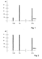
- Figure 1 shows typical return signal components from biological tissues, at the first subharmonic of the fundamental transmission frequency, at the fundamental transmission frequency, and at the first harmonic of the fundamental transmission frequency.
- Figure 2 shows typical return signal components from contrast agents at the three above mentioned frequencies.
- the present invention provides a method wherein said three return signal components are determined and separated, and their respective amplitudes are stored to generate a diagram like that shown in Figures 1 and 2, and discriminate between tissue reflectors and contrast agent reflectors. Accordingly, an image is reconstructed by using the reflected signal component at the same frequency as the fundamental transmission frequency, as a B-mode image, for instance a grey-scale B-mode image.
- the discrimination between contrast agents and tissues allows to identify the B-mode image areas that correspond to the areas in which contrast agents were detected, in the manner described above.
- Subharmonic and harmonic components are not used to construct images, but only for the above mentioned reflector nature discrimination.
- the image areas corresponding to the reflectors that were identified as contrast agents are displayed on the B-mode grey scale generated by the fundamental component of the return signal by color variations or chrominance variations of the image areas.
- the method of the invention is particularly adapted to the purposes of the two imaging modes, and yields a high quality background image, and a highly reliable indication of the flow presence, as well as a highly reliable localization of said flows.
- the frequency bands of probes are generally of about 1.6MHz to 3.2 MHz. If a center frequency of 2.4 MHz is selected, then both the subharmonic and the harmonic frequencies are outside the probe band.
- probes may be provided that have higher frequency bands, or multiple transducer arrays, each being optimized for such a frequency band that at least one of the arrays includes the subharmonic frequency and at least one of the arrays includes the second harmonic of the fundamental frequency.
- a first transducer array might include in its band a frequency of 2.4 MHz, whereas a second array is optimized for a frequency band including the first subharmonic frequency, i.e. 1.2 MHz and a third array is optimized for receiving the first harmonic frequency, i.e. 4.8 MHz.
- This arrangement might obviate the above mentioned problems but is expensive and inconvenient for the user, who should replace the probe at each imaging process with the method of the invention and who would have to calibrate and optimize the system at each probe replacement.
- the return signal component having the fundamental frequency of the transmit beam is separated and processed in the return signal. This is shown in the two superimposed left diagrams of Figure 3. Referring to the previous example of a probe having a lower band limit of 1.6 MHz and an upper band limit of 3.2 MHz, the fundamental frequency of the transmit beam and the frequency of the detected return signal component is of 2.4 MHz.
- the second transmit beam is transmitted at a frequency equal to the lower band limit and the return signal component whose frequency corresponds to the second harmonic of the fundamental transmission frequency is obtained from the return signal. This is shown in the central column of the diagram of Figure 3.
- the transmit beam is transmitted at a frequency of 1.6 MHz, whereas the return signal includes the second harmonic component having a frequency of 3.2 MHz.
- the third transmit beam has a frequency corresponding to the upper band limit, whereas the component at the first subharmonic of said transmit signal is detected from the return signal.
- the fundamental transmission frequency is of 3.2 MHz
- the first subharmonic frequency is of 1.6 MHz.
- the above described mode comprising a scan sequence, whereby three transmit beams having the above mentioned frequencies are successively transmitted, has the advantage of optimally adjusting the transmission parameters relative to the designed function of the corresponding return signal components.
- the transmit beam at the center frequency, for detecting the return signal component at said center frequency is designed for B-mode background imaging and may be optimized for this purpose.
- the transmit beam at said center frequency of the band is a short, i.e. broad band, pulse. This allows to maintain an enhanced resolution and an optimized signal-to-noise ratio, as well as to reduce the presence of artifacts.
- the transmit beams optimized to receive harmonic and subharmonic components of the return signal are formed by narrow band, i.e. long duration pulses, which are definitely inadequate to yield high quality images, but certainly more effective to excite nonlinear reflection responses from contrast agents.
- FIG. 5 shows a chart of an ultrasonic imaging apparatus operating according to the above embodiment of the inventive method.
- a central controller 1 controls the transmitter 2 and the receiver 3, which are in turn connected to the transducers through a switch 4, the latter being synchronized with the transmit and receive steps.
- the signal that comes from the receiver 3 is bandpass filtered 5, 5', 5'', relative to the fundamental frequency of the transmit beam, the second harmonic of the fundamental transmission frequency and the first subharmonic of the fundamental transmission frequency.
- the application of these filters is synchronized with the sequence of transmit beams optimized for receiving the corresponding reflected signal component, at the above frequencies.
- the return signal components for each reflected point along each scan line are stored 6, 6', 6''. Particularly, the amplitude of said components is stored.
- the fundamental components of return signals are processed 10 for generating a B-mode image, to be displayed on the monitor 9.
- the discriminator controls the monitor pixel aspect in the areas of the B-mode image, i.e. the background image, corresponding to areas of the body under examination in which return signals have been identified that were assumed as being generated by contrast agents, according to the above method.
- the aspect of these pixels, corresponding to contrast agent signal contributions is controlled, for instance, by appropriate color assignment or chrominance variations.
- the image obtained thereby is a high quality image, in terms of resolution and sharpness, relative to the background B-mode image, and is highly reliable for the identification of contrast agents.
- the return signal components at the transmission frequency, the harmonic frequency and the subharmonic frequency cannot be scanned by a succession of identically focused transmit beams, each optimized for one of said return signal components, as each of the three successive beams generates a return signal for a different condition of the subject being examined, because, in the time between two successive transmit beams, the subject being examined, for instance the organ, has moved, therefore the component of the return signal for a successive transmit beam cannot be compared with the preceding one.
- the invention provides an alternative embodiment, wherein techniques are used for encoding and modulating the transmit beam frequency, which allow to modulate the transmission frequency within the duration of the transmit beam.
- the frequency of the transmit beam is modulated linearly within the duration of the transmit beam, by varying the transmit beam frequency from a start value to an end value, which form the limits of a predetermined band width.
- the frequency of the transmit beam may be varied linearly within the duration of the transmit beam from the frequency corresponding to the lower limit of the probe band to the frequency corresponding to the upper limit of the probe band.
- a demodulation of the frequency spectrum is required, which demodulation is correlated in time with the transmission modulation.
- Figure 4 shows the waveform of the transmitted signal for a linear chirp passing from a lower limit of the probe band, equal to 1/2 Fo to an upper limit of the band, equal to 2Fo. Note that the wavelength decreases with time.
- modulation types are provided which are not continuous and linear and involve phase and frequency hops in schemes of discrete steps.
- One of such techniques is known as Pseudo Chirp and is described in Coded Excitation System for Improving the Penetration of Real-Time Phased Array Imaging Systems" , Matthew O'Donnel, IEE Transaction on Ultrasonics, Ferroelectrics and Frequency Control, Vol. 39, No.3 May 1992
- Demodulation or decoding is generally performed by correlated filtering of the return signal.
- Several other encoding and decoding techniques are described in US 6,494,839, US 5,961,463, US 5,980,459 and US 6,050,947 which are integrated herein as a reference.
- FIG. 6 An apparatus for implementing the method of the invention, which uses techniques for encoding/decoding or frequency modulation and demodulation for transmitted and received signal is schematically shown in Fig. 6.
- parts that are equal to or have the same function as parts of the device as shown in Figure 5 are denoted with the same reference numbers.
- Transmission, encoding or modulation, and reception and decoding or demodulation are controlled by a controller 1.
- the transmitter 2 has encoder/modulator functions and the receiver 3 has decoder/demodulator functions.
- Decoding or demodulation is often provided by correlations or convolutions and filtering. Particularly, a so-called FIR filtering process is often used.
- the decoding or demodulation process yields the three separate components of the return signal for the single transmitted beam. Said components are designated as Fo, 2Fo and Fo/2 in Figure 6. Now, the amplitudes of said components are detected and the processing thereof is substantially identical to the one discussed with reference to Figure 5.
- the invention provides the use of a different technique, based on the Wavelet transform.
- the steps of said technique consist in generating a spectrum of the transmit beam including the above mentioned three frequencies and in subsequently detecting, in a correlated manner, the spectral map of the return signal.
- the steps of this technique include sampling and digitization of the return signal, and subsequent processing by a Wavelet transform. Then, the spectral map may be analyzed, for instance, by comparing it with reference spectral maps, which are used to identify the spectral map type and the reflector nature. This method is described in greater detail in US 6,066,098, granted to the owner hereof, and whose content is integrated herein by reference.
- Figure 7 shows a simplified scheme of an apparatus operating by detecting the spectral map of the return signal and comparing it with predetermined unique spectral maps to recognize the reflector nature specific map.
- the signal coming from the RX receiver is sampled and digitized 11 and subjected to the Wavelet transform 12.
- a spectral map is thus obtained for each reflector, which map is compared 13 with reference spectral maps stored in a memory 14 of the apparatus.
- the reflector is assigned a reflector type.
Abstract
Description
- The invention addresses an ultrasound imaging method combined with the presence of contrast agents in the body under examination, comprising the steps of:
- transmitting, by using an array of electroacoustic transducers, at least one beam of acoustic waves into one body under examination, which carries contrast agents, said waves being transmitted at a first fundamental transmission frequency and being focused on at least one scan line;
- receiving the acoustic beam reflected from the body under examination and the contrast agents, by using an array of receiving electroacoustic transducers, which transducers generate an electric return signal, corresponding to the reflected acoustic beam along said at least one scan line;
- separating the at least one harmonic or subharmonic components and the fundamental component of said return signal;
- generating one image from at least one of the return signal components, at the fundamental frequency, at the harmonic and/or subharmonic frequency.
-
- In diagnostic ultrasonic imaging, several modes are known for processing electroacoustic return signals. These different modes have the purpose of displaying different types of tissues or objects that may be more or less echogenic.
- Static tissues typically have a good echogenicity and are optimally detectable by ultrasonic imaging at the fundamental frequency by using the so-called B-mode. In this mode, as is well known, the envelope of the return signal is detected, whose amplitude is correlated to a grey scale, thereby forming an image. B-mode images at the fundamental transmission frequency are high-quality images, as the transmit signal may consist of a broadband pulse, i.e. a very short pulse, which ensures an optimized resolution.
- Static tissues, and particularly soft tissues, also generate nonlinear reflected signals. The generated return signal not only contains a fundamental component, i.e. at the same frequency as the transmit beam, but also comprises nonlinear components, as components at the second or higher-order harmonics of the fundamental transmission frequency.
- Highly perfused tissues or blood flows or other body flows are poorly echoghenic, i.e. generate reflection contributions well below the intensity of the reflection contributions generated by static tissues. This limitation was accordingly obviated by using substances that amplify the reflection response and are introduced in said blood flows. These substances, known as contrast agents, have a strongly nonlinear reflection response, and therefore generate return signal contributions at the second harmonic of the transmit beam fundamental frequency. The so-called harmonic imaging mode was developed for contrast agent ultrasonic imaging, and allows to remove the fundamental frequency contributions of the return signal and to use the second harmonic components generated by contrast agents for image reconstruction.
- Nevertheless, as mentioned above about soft tissues, these tissues also generate nonlinear contributions of the return signals, therefore the presence of blood flows with contrast agents prevents from differentiating between the return signal due to a soft tissue and a return signal due to a contrast agent.
- US 6,066,098 teaches an ultrasonic imaging method which does not only use a certain frequency of the return signal, but acquires the whole spectrum of the received signal frequencies. As this spectrum is characteristic for each type of tissue, this method allows to identify the type of tissue that generated the reflected signal at a predetermined scanning depth and to differentiate tissue contributions from contrast agent contributions in the return signal.
- From documents US 6,290,647 and US 6,117,082, it is known to use another characteristic of contrast agents for ultrasonic imaging thereof, and differentiation thereof from tissues. Indeed, when the transmit signal is exposed to an appropriate mechanical pressure, contrast agent return signals may be excited which have signal components at a subharmonic of the transmit signal frequency. Such subharmonic frequency is not substantially present in the reflected signals generated by physiological tissues. The two documents provide that ultrasonic imaging of regions that carry contrast agents may be performed by using said components of the subharmonic signal, alternatively or in addition to the harmonic component of the return signal.
- Nevertheless, the excitation of the subharmonic components of the return signal generated by contrast agents requires the transmit pulses to be relatively long, and such time length of transmit pulses causes an image quality degradation in terms of resolution, presence of side lobes and generation of artifacts.
- On the other hand, traditional B-mode images, obtained by using the linear component of the received signal allow, as mentioned above, the generation of high quality images.
- It shall be further noted that the use of contrast agent signals is not generally designed for B-mode imaging, hence to imaging in a narrow sense, but especially for detecting the presence of contrast agents and possibly the perfusion characteristics thereof, or for determining the speed or amount of flow.
- Due to the above, the methods taught by US 6,290,647 and 6,117,082 involve a number of image quality restrictions.
- Problems also arise in the excitation and reception of subharmonic signals, as the band widths of ultrasonic probes are generally insufficient to ensure the reception of harmonic and subharmonic frequencies of the fundamental transmission frequency.
- The invention has the object of providing a method that allows to safely distinguish contrast agents from the remaining tissues, preferably of the biological type, that form the body under examination, and of providing an imaging mode that combines the B-mode image quality of the linear components of the received signal with the information that is expected to be acquired by using contrast agents, i.e. substantially the presence thereof.
- A further object of the present invention is to allow the inventive method to be implemented to continuously moving organs, e.g. the heart.
- The invention achieves the above purposes by providing a method as described above, in which:
- the fundamental component, the harmonic component and the subharmonic component are separated in the return signal;
- the amplitudes of the return signal are stored for each of the fundamental, harmonic or subharmonic frequency components at each reflected point along said scan line;
- the nature of the reflected point along the scan line being discriminated depending on the amplitudes of the fundamental, harmonic and subharmonic components of the return signal and
- the nature of the reflected point being assumed as a contrast agent when the subharmonic component of the return signal has an amplitude above a predetermined minimum amplitude.
-
- Therefore, the identification, in a return signal of a reflected point along a scan line, of a return signal component whose frequency is equal to a subharmonic of the transmit signal frequency, allows to determine the nature of the reflected point, i.e. whether the reflected point is formed by the contrast agent or a tissue.
- According to an improvement, the above method is applied to the return signals which correspond to a plurality of adjacent scan lines, which define a scan plane.
- According to the reflected point nature discriminating analysis of the present method, the reflected points along a scan line to be assumed as contrast agents are those whose return signal has a fundamental component and a subharmonic component having similar or substantially identical amplitudes and a harmonic component having a lower amplitude than the fundamental and the harmonic components.
- In fact, it was found that, by exciting with an appropriate acoustic pressure the nonlinear reflected component at the subharmonic of the fundamental transmission frequency, the intensity of said subharmonic component is substantially equal to that of the fundamental transmission frequency of the return signal.
- In the method of the present invention, the second harmonic and subharmonic components are not used for ultrasonic imaging, but only to discriminate the areas of said image that correspond to regions of the body under examination which carry the contrast agent. Therefore, the method of the invention includes the steps of:
- generating a B-mode panoramic background image of the fundamental transmission frequency component of the return signal
- providing a differential display, over the B-mode background image, by assigning one or more specific display colors and/or by chrominance variations, to the areas of said background images corresponding to the reflected points that are defined as contrast agents.
-
- Regarding amplitude comparisons between the various frequency components of the return signal, the method of the invention provides a comparison of relative and not absolute amplitude values. In fact, there is no convenience in providing absolute amplitude thresholds for the harmonic, subharmonic and fundamental frequency components of the return signal, as the absolute amplitude value may vary depending on the type of tissue being examined. To this end, the invention provides an amplitude standardization for the above three components of the return signal, by using, as a reference, the amplitude value obtained for the fundamental transmission frequency component of the return signal. A simple relativization method consists in dividing the amplitudes of the three frequency components of the return signal by the amplitude of the return signal component at the fundamental transmission frequency, for each reflected point along each scan line.
- As the propagation of the acoustic pulse in the body under examination is frequency-dependent, a proper reflector nature discriminating analysis, based on the amplitudes of the three frequency components of the return component, i.e. the fundamental, harmonic and subharmonic components, may be performed, according to the invention thanks to an amplitude standardization step, consisting in that, for each return signal component, at the fundamental transmission frequency, at the harmonic frequency and at the subharmonic frequency, an amplitude compensation is provided, which is a function of the penetration depth, i.e. the propagation time and the signal component frequency.
- The inventive method may be practically implemented in several different modes. In all these modes, the problem arises of accounting for the fact that ultrasonic probes, i.e. the transducer arrays that form them, generally have a narrow frequency band. The frequency bands of probes are generally of 1.6MHz to 3.2 MHz.
- The implementation of this method requires additional steps to be provided, to overcome probe band limitations.
- A feasible, but cost ineffective and functionally inconvenient arrangement, consists in providing a specific probe for imaging processes with the above method. Nevertheless, apart from the additional cost of a special probe, the user is expected to connect the probe every time and reset the imaging apparatus to optimize its settings relative to the new probe.
- Regarding the above mentioned narrow band of ultrasonic probes, the method implementation modes may be differentiated depending on specific applications relative to the body under examination. Particularly referring to diagnostic imaging, two specific fields of use are recognized. A first field of use is the radiological field, in which the regions of the body under examination include no moving tissues or organs, except blood or lymphatic flows.
- Here, a simplified implementation mode may be provided. In fact, the time factor, i.e. the duration of the signal transmit and receive cycle is not critical, as organs are static and contrast agents remain therein for sufficiently long times.
- Therefore, in the above conditions, the invention provides successive transmission of three identically focused ultrasonic beams, which are optimized for the fundamental frequency, the harmonic frequency and the subharmonic frequency respectively. In combination therewith, a successive reception is also provided of three identically focused ultrasonic beams, which are optimized for the fundamental frequency, the harmonic frequency and the subharmonic frequency respectively.
- More specifically, the method of the invention provides, in combination with the above, an array of transducers having a predetermined transmit/receive band width, wherein an upper band limit is defined which is twice the lower band limit, three identically focused beams being successively generated, having a center frequency between the upper and the lower limits, a frequency corresponding to the lower limit of said band, and a frequency corresponding to the upper limit of said band, whereas the return signal associated to the transmit signal at the center frequency, is used for receiving the center or fundamental frequency component of the return signal, the return signal associated to the transmit signal at the lower band frequency is used for receiving the harmonic component of the return signal, and the return signal associated to the transmit signal at the upper band limit is used for receiving the subharmonic component of the return signal.
- Hence, for each scan line, the three fundamental, harmonic and subharmonic components of the return signal may be detected without replacing the probe and in a very simple manner.
- In addition, the above arrangements also allow to further optimize the three identically focused transmit beams relative to the return signal frequency component to be excited and with reference to the utilization of said signal component.
- Indeed, the transmit beam may be appropriately optimized for the fundamental component of the return signal regarding the function of said component to provide information for generating the B-mode background image. Here, the fired transmit beam may be formed by at least one broad band, i.e. short duration pulse. This provides a better signal-to-noise ratio and an enhanced resolution.
- However, for harmonic and subharmonic components, energy must be transferred to the reflectors. In fact, in order to excite particularly subharmonic components a sufficient amount of energy must be transferred to the reflectors whereas, as reflectors are contrast agents, peak energy is not only unnecessary, but even harmful, as if acoustic pressure gets above a certain limit, there is the risk of breaking the microbubbles that form the contrast agents. Hence, in this case, the transmit beam is optimized for the harmonic and/or subharmonic component of the return signal, to be a narrow band signal, i.e. having a long duration. This obviously involves a decreased signal-to-noise ratio, a low resolution and the presence of artifacts. Nevertheless, as the method of the invention provides that such components only have reflector nature discriminating functions, such effects that might be considered inconvenient for imaging, do not affect the result or the function of harmonic and subharmonic components of the signal. Also, transmit beams having a predetermined acoustic pressure and a long duration are optimal for exciting harmonic and subharmonics.
- Thanks to the above arrangements, the method of this invention yields a B-mode background image generated by the fundamental transmission frequency component of the return signal, the so-called linear component of the return signal, that has a high quality and provides an enhanced resolution and an optimized signal-to-noise ratio, whereas reflector nature discrimination is performed by using transmit beam firing parameters which ensure the best excitation effect on harmonic and subharmonic components, thereby providing an optimized detection of the presence of said components and amplitude measurement thereof.
- In addition to the use of a traditional transducer array, the method of the invention allows the transmission arrangements to be used for a particular transducer array, wherein said transducer array is divided into three different groups of transducers. The transducers of each of said three groups are excited to generate a transmit beam at the center frequency between the upper and the lower band limits, a transmit beam at the lower band limit frequency and a transmit beam at the upper band limit frequency.
- In accordance with the above arrangements, the transducer groups are excited in succession, and are identically focused, i.e. on the same scan line.
- The above transmitting steps, providing a succession of three identically focused transmit beams, each of which beams is optimized for exciting and receiving, by using the same probe, one of the three components of the return signal, at the transmission frequency, at the harmonic of the transmission frequency and at the subharmonic of the transmission frequency respectively, cannot be executed when the imaging method is used for bodies under examination containing moving tissues or organs, e.g. in cardiologic imaging applications. Here, the triplet of transmit beams would be transmitted at different times, wherein the moving organ exhibits different conditions. Therefore, the return signals at the three different frequency components would relate to a different moving organ condition for each frequency component of the return signal, thereby providing a less accurate evaluation.
- In the case of moving organs within the body under examination, the invention provides an implementation mode that is different from the one that described herein for radiological applications.
- As a rule, in order to also implement the inventive method for imaging bodies containing moving organs or tissues or body parts, the invention provides the combination with a probe or a transducer array having a predetermined transmit/receive frequency band width range, wherein an upper band limit may be defined which is twice the lower band limit.
- In order to prevent the three successive transmission events of the radiological solution, this application allows, in principle, to use any type of method allowing to introduce, within the transmit beam duration, the three different frequencies, i.e. the center frequency of the transducer array band between the lower and the upper limits and the frequencies of the lower and upper limits. In principle, several methods are known for detecting the frequency spectrum of the return signal to identify the transmission frequency, the harmonic frequency and the subharmonic frequency components of said signal.
- According to a first embodiment, the transmitted signal may be encoded to include the three fundamental, harmonic and subharmonic frequencies, thanks to the fact that the transmit beam is linearly modulated between the lower frequency limit and the upper frequency limit of the transducer band, within the duration of the transmit beam, whereas the received return signal is accordingly demodulated to extract the return signal components at the fundamental frequency, corresponding to the center band frequency, at the harmonic frequency, corresponding to the upper band limit, and at the subharmonic frequency, corresponding to the lower band limit. This is a so-called pulse modulation encoding, known as CHIRP. CHIRP modulation has been used for a long time in the radar field and may also find application in the electroacoustic field, thanks to the fact that the signals in use are still RF signals. A more detailed description of chirp modulation is contained in "Spaceborn Radar Remote Sensing: Applications and Techniques", Charles Elachi, Institute of Electrical and Electronics Engineers Press, New York, December 1988. The document "Coded Excitation System for Improving the Penetration of Real-Time Phased Array Imaging Systems" , Matthew O'Donnel, IEE Transaction on Ultrasonics, Ferroelectrics and Frequency Control, Vol. 39, No. 3 May 1992, describes the application of a "Pseudo CHIRP" method in ultrasonic imaging, and said document is integrated herein by reference.
- According to a further alternative embodiment, the return signal is demodulated for extracting the center band frequency, the upper band limit frequency and the lower band limit frequency components of the signal by using a time-frequency transform. A particular embodiment of the above method provides the use of a transform known as wavelet transform.
- Here, a spectral map of the return signal may be generated to identify the center frequency between the upper limit and the lower limit of the band and the lower and upper limit frequencies of the band by sampling the return signal, and processing the sampled and digitized signal by a discrete wavelet transform. Then, the spectral map may be analyzed, for instance, by comparing it with reference spectral maps, which are used to identify the spectral map type and the reflector nature. This method is described in greater detail in US 6,066,098, granted to the owner hereof, and whose content is integrated herein by reference.
- The above are not the only arrangements that may be used in combination with the method of the invention. Other arrangements may be used for encoding the transmitted signals and for filtering the received signals by correlation, such as those described in US 6,494,839, US 5,961,463, US 5,980,459 and US 6,050,947, which are integrated herein by reference.
- In most of the above mentioned ultrasonic pulse encoding methods, a considerable technical advantage is provided, in addition to the advantage of concentrating the excitation and detecting the fundamental, harmonic and subharmonic components within a single transmit and receive event, which advantage consists in that, while the pulse has a relatively long duration, hence a low resolution, the encoding and correlated decoding thereof causes a signal compression during reception, which allows to obviate the long duration of the signal and to obtain images whose quality is similar to the that obtained by using broad band, short duration transmit pulses.
- This advantage is also combined with the fact that the peak acoustic pressure during transmission does not exceed contrast agent destruction limits, and contrast agents are preserved from such destruction but, thanks to the signal compression obtained by the coding and decoding process, amplitude peaks are obtained, for at least some of the spectral components of the return signal, that have a sufficient amplitude for optimized imaging.
- The characteristics of the inventive method and the advantages derived therefrom will appear more clearly from the following description of a few non limiting embodiments, illustrated in the annexed drawings, in which:
- Fig. 1 shows the discretized spectrum of the return signal, at the fundamental transmission frequency, at the second harmonic of the fundamental transmission frequency and at the first subharmonic of the fundamental frequency of the transmit signal, said signal being a return signal derived from a reflector consisting of a tissue of a body under examination.
- Fig. 2 is a diagram like that of Figure 1, in which the spectrum relates to the return signal deriving from the contrast agent as a reflector.
- Fig. 3 is a diagram that shows the successive transmission of three identically focused beams at different fundamental transmission frequencies, such as to ensure that the return signal components corresponding to the fundamental transmission frequency, the subharmonic and the harmonic of each respective fundamental transmission frequency, all fall within the frequency band of an array of transmitting and receiving electroacoustic transducers.
- Fig. 4 shows an example of linear encoding of a transmit pulse frequency according to the CHIRP encoding method.
- Fig. 5 schematically shows an ultrasonic imaging apparatus whereby the method of this invention may be implemented in a variant that provides successive firing of three identically focused transmit beams having different fundamental transmission frequencies, like in the example of Figure 3.
- Fig. 6 schematically shows an ultrasonic imaging machine for implementing the inventive method, in which the transmit beam is encoded or frequency modulated and the return signal is decoded/frequency demodulated, while being correlated to the transmit beam.
- Fig. 7 schematically shows an ultrasonic imaging apparatus for implementing the method of this invention, in which the frequency spectrum map of the return signal is determined, which spectrum is compared with typical reference spectra for the return signal due to the tissue and for the reflected signal due to contrast agents.
-
- The principle of the present invention consists in that ultrasound imaging of a body under examination is performed by exciting reflection echoes having components at the fundamental frequency of the exciting signal, at the subharmonic of said fundamental frequency and at the harmonic of said fundamental frequency. The reflector nature may be determined by analyzing the amplitudes of the ultrasonic imaging return signal for each reflected point, for instance along a scan line. There exists the need, in ultrasonic imaging, of differentiating whether the received return signal is due to the tissue or to a contrast agent that was appropriately used. While contrast agents are known to have a nonlinear reflection behavior, causing the presence of a return signal component at a harmonic frequency, e.g. the second harmonic of the fundamental frequency of the reflected signal, such nonlinear reflection behavior is also exhibited by biological tissues, particularly soft tissues. Hence, it is currently difficult to discriminate whether the nonlinear reflector that generates reflected signals having second harmonic components is a contrast agent or a nonlinear reflector, for instance, a soft biological tissue.
- Such discrimination is of the utmost importance, as contrast agents are used to allow ultrasonic imaging of blood or lymphatic flows, which are known to be poorly echogenic and provide too little a contribution to the fundamental component, as compared with the same contribution generated by tissues. Therefore, it is important to positively identify the nature of the reflector that generated the harmonic component of the return signal.
- To this end, it was found that, if contrast agents were excited by appropriate acoustic pressures and by an appropriate energy transfer, they also generated, within the ultrasonic imaging return signal, subharmonic components of said signal, particularly at a first subharmonic of the fundamental transmission frequency.
- On the other hand, such subharmonic component is almost absent or has very low amplitudes in return signals due to the reflection by either soft or hard biological tissues.
- If contrast agents are appropriately excited, they generate return signal components at the first subharmonic of the fundamental frequency of the transmit signal, whose amplitudes are similar in all respects to those of the fundamental frequency component of the reflected signal.
Figure 1 shows typical return signal components from biological tissues, at the first subharmonic of the fundamental transmission frequency, at the fundamental transmission frequency, and at the first harmonic of the fundamental transmission frequency. - Figure 2 shows typical return signal components from contrast agents at the three above mentioned frequencies.
- Such difference between the spectra of the two return signals somewhat constitutes a discriminant for determining the difference between reflector types, i.e. tissues and contrast agents.
- The present invention provides a method wherein said three return signal components are determined and separated, and their respective amplitudes are stored to generate a diagram like that shown in Figures 1 and 2, and discriminate between tissue reflectors and contrast agent reflectors. Accordingly, an image is reconstructed by using the reflected signal component at the same frequency as the fundamental transmission frequency, as a B-mode image, for instance a grey-scale B-mode image.
- On the other hand, the discrimination between contrast agents and tissues allows to identify the B-mode image areas that correspond to the areas in which contrast agents were detected, in the manner described above. Subharmonic and harmonic components are not used to construct images, but only for the above mentioned reflector nature discrimination. The image areas corresponding to the reflectors that were identified as contrast agents are displayed on the B-mode grey scale generated by the fundamental component of the return signal by color variations or chrominance variations of the image areas.
- As the B-mode background image obtained by the fundamental transmission frequency component of the return signal generally has an optimized resolution and as contrast agents are only used to identify the presence of a flow, the method of the invention is particularly adapted to the purposes of the two imaging modes, and yields a high quality background image, and a highly reliable indication of the flow presence, as well as a highly reliable localization of said flows.
- However, the implementation of the inventive method must account for the fact that ultrasonic probes have low-amplitude transmit and receive frequency bands. The frequency bands of probes are generally of about 1.6MHz to 3.2 MHz. If a center frequency of 2.4 MHz is selected, then both the subharmonic and the harmonic frequencies are outside the probe band.
- As a general rule, probes may be provided that have higher frequency bands, or multiple transducer arrays, each being optimized for such a frequency band that at least one of the arrays includes the subharmonic frequency and at least one of the arrays includes the second harmonic of the fundamental frequency. Hence, a first transducer array might include in its band a frequency of 2.4 MHz, whereas a second array is optimized for a frequency band including the first subharmonic frequency, i.e. 1.2 MHz and a third array is optimized for receiving the first harmonic frequency, i.e. 4.8 MHz. This arrangement might obviate the above mentioned problems but is expensive and inconvenient for the user, who should replace the probe at each imaging process with the method of the invention and who would have to calibrate and optimize the system at each probe replacement.
- In radiological imaging, i.e. of bodies or regions of bodies containing stationary tissues and organs, such probe replacement problem might be obviated by generating a succession of three transmit beams for each scan line, each of which beams is optimized to transmit a fundamental frequency generating, within the frequency band of the probe, return signals having a fundamental frequency, a frequency equal to the first subharmonic of the fundamental transmission frequency and a frequency equal to the second harmonic of the fundamental transmission frequencies, which are all within the probe band. A simple way to obtain this is schematically shown in Figure 3. When considering an ultrasonic imaging probe whose frequency band has a lower limit corresponding to half the upper limit, the three transmit beams are generated, the first being at the center frequency between the lower limit and the upper limit of the probe band. Here, the return signal component having the fundamental frequency of the transmit beam is separated and processed in the return signal. This is shown in the two superimposed left diagrams of Figure 3. Referring to the previous example of a probe having a lower band limit of 1.6 MHz and an upper band limit of 3.2 MHz, the fundamental frequency of the transmit beam and the frequency of the detected return signal component is of 2.4 MHz.
- The second transmit beam is transmitted at a frequency equal to the lower band limit and the return signal component whose frequency corresponds to the second harmonic of the fundamental transmission frequency is obtained from the return signal. This is shown in the central column of the diagram of Figure 3. In the above example of a probe, the transmit beam is transmitted at a frequency of 1.6 MHz, whereas the return signal includes the second harmonic component having a frequency of 3.2 MHz.
- In the right column of the diagram of Figure 3, the third transmit beam has a frequency corresponding to the upper band limit, whereas the component at the first subharmonic of said transmit signal is detected from the return signal. With reference to the above probe example, the fundamental transmission frequency is of 3.2 MHz, whereas the first subharmonic frequency is of 1.6 MHz.
- The above described mode comprising a scan sequence, whereby three transmit beams having the above mentioned frequencies are successively transmitted, has the advantage of optimally adjusting the transmission parameters relative to the designed function of the corresponding return signal components. Hence, for example, the transmit beam at the center frequency, for detecting the return signal component at said center frequency is designed for B-mode background imaging and may be optimized for this purpose. In fact, in the method of the present invention, the transmit beam at said center frequency of the band is a short, i.e. broad band, pulse. This allows to maintain an enhanced resolution and an optimized signal-to-noise ratio, as well as to reduce the presence of artifacts.
- Regarding the transmit beams optimized to receive the subharmonic and harmonic components of the transmission signal, there is no need for these components to provide a broad band pulse, as said subharmonic and harmonic components are not used for image reconstruction. Their presence is only needed to identify the nature of reflectors, i.e. to recognize whether reflectors are tissues or contrast agents.
- Nevertheless, for a proper excitation of harmonic and subharmonic components of the return signal, especially when contrast agents are present, the amplitude of the transmitted signal is not so critical as the amount of energy transferred to contrast agents, provided that acoustic pressure thresholds are not exceeded, in which case contrast agents would be broken. Therefore, the transmit beams optimized to receive harmonic and subharmonic components of the return signal are formed by narrow band, i.e. long duration pulses, which are definitely inadequate to yield high quality images, but certainly more effective to excite nonlinear reflection responses from contrast agents.
- Figure 5 shows a chart of an ultrasonic imaging apparatus operating according to the above embodiment of the inventive method. Here, a central controller 1 controls the
transmitter 2 and thereceiver 3, which are in turn connected to the transducers through aswitch 4, the latter being synchronized with the transmit and receive steps. The signal that comes from thereceiver 3 is bandpass filtered 5, 5', 5'', relative to the fundamental frequency of the transmit beam, the second harmonic of the fundamental transmission frequency and the first subharmonic of the fundamental transmission frequency. The application of these filters is synchronized with the sequence of transmit beams optimized for receiving the corresponding reflected signal component, at the above frequencies. The return signal components for each reflected point along each scan line are stored 6, 6', 6''. Particularly, the amplitude of said components is stored. These values are standardized relative to the fundamental frequency amplitude and compared 7, 7', 7'' with appropriate threshold values, particularly at least as regards the subharmonic component of the return signal. The comparison result is routed to adiscriminator 8, which generates signals for controlling adisplay monitor 9 for the pixels of said monitor that correspond to the image areas in which the signal received from the body under examination is due to contrast agents. - The fundamental components of return signals are processed 10 for generating a B-mode image, to be displayed on the
monitor 9. The discriminator controls the monitor pixel aspect in the areas of the B-mode image, i.e. the background image, corresponding to areas of the body under examination in which return signals have been identified that were assumed as being generated by contrast agents, according to the above method. The aspect of these pixels, corresponding to contrast agent signal contributions is controlled, for instance, by appropriate color assignment or chrominance variations. - The image obtained thereby is a high quality image, in terms of resolution and sharpness, relative to the background B-mode image, and is highly reliable for the identification of contrast agents.
- The above described method, which allows to obviate the band width limits of prior art ultrasonic probes, without using a special ultrasonic probe, cannot unfortunately be used when the body under examination or the part thereof is a moving organ, tissue or part.
- If this is the case, the return signal components at the transmission frequency, the harmonic frequency and the subharmonic frequency cannot be scanned by a succession of identically focused transmit beams, each optimized for one of said return signal components, as each of the three successive beams generates a return signal for a different condition of the subject being examined, because, in the time between two successive transmit beams, the subject being examined, for instance the organ, has moved, therefore the component of the return signal for a successive transmit beam cannot be compared with the preceding one.
- In these conditions, the invention provides an alternative embodiment, wherein techniques are used for encoding and modulating the transmit beam frequency, which allow to modulate the transmission frequency within the duration of the transmit beam.
- As mentioned above, some of these techniques are known and currently used.
- According to a first variant embodiment, the frequency of the transmit beam is modulated linearly within the duration of the transmit beam, by varying the transmit beam frequency from a start value to an end value, which form the limits of a predetermined band width. Referring to the probe that was mentioned above as an example, the frequency of the transmit beam may be varied linearly within the duration of the transmit beam from the frequency corresponding to the lower limit of the probe band to the frequency corresponding to the upper limit of the probe band. During reception, a demodulation of the frequency spectrum is required, which demodulation is correlated in time with the transmission modulation.
- This technique is known from RADAR technology as CHIRP. Figure 4 shows the waveform of the transmitted signal for a linear chirp passing from a lower limit of the probe band, equal to 1/2 Fo to an upper limit of the band, equal to 2Fo. Note that the wavelength decreases with time.
- Other modulation types are provided which are not continuous and linear and involve phase and frequency hops in schemes of discrete steps. One of such techniques is known as Pseudo Chirp and is described in Coded Excitation System for Improving the Penetration of Real-Time Phased Array Imaging Systems" , Matthew O'Donnel, IEE Transaction on Ultrasonics, Ferroelectrics and Frequency Control, Vol. 39, No.3 May 1992
- Demodulation or decoding is generally performed by correlated filtering of the return signal. Several other encoding and decoding techniques are described in US 6,494,839, US 5,961,463, US 5,980,459 and US 6,050,947 which are integrated herein as a reference.
- An apparatus for implementing the method of the invention, which uses techniques for encoding/decoding or frequency modulation and demodulation for transmitted and received signal is schematically shown in Fig. 6. Here, parts that are equal to or have the same function as parts of the device as shown in Figure 5 are denoted with the same reference numbers.
- Transmission, encoding or modulation, and reception and decoding or demodulation are controlled by a controller 1. The
transmitter 2 has encoder/modulator functions and thereceiver 3 has decoder/demodulator functions. By encoding, in the transmit signal, the frequency components optimized for exciting the return signal components at the fundamental transmission frequency, at the harmonic and at the subharmonic of the transmission frequency, it is possible to introduce in a single transmit beam all the required optimizations to maintain the subharmonic and harmonic frequencies within the probe band. - Decoding or demodulation is often provided by correlations or convolutions and filtering. Particularly, a so-called FIR filtering process is often used. The decoding or demodulation process yields the three separate components of the return signal for the single transmitted beam. Said components are designated as Fo, 2Fo and Fo/2 in Figure 6. Now, the amplitudes of said components are detected and the processing thereof is substantially identical to the one discussed with reference to Figure 5.
- In addition to the above transmit signal encoding techniques, techniques may be also provided for detecting the spectral map of the return signal.
- In this case, the invention provides the use of a different technique, based on the Wavelet transform. The steps of said technique consist in generating a spectrum of the transmit beam including the above mentioned three frequencies and in subsequently detecting, in a correlated manner, the spectral map of the return signal.
- The steps of this technique include sampling and digitization of the return signal, and subsequent processing by a Wavelet transform.
Then, the spectral map may be analyzed, for instance, by comparing it with reference spectral maps, which are used to identify the spectral map type and the reflector nature. This method is described in greater detail in US 6,066,098, granted to the owner hereof, and whose content is integrated herein by reference. - Figure 7 shows a simplified scheme of an apparatus operating by detecting the spectral map of the return signal and comparing it with predetermined unique spectral maps to recognize the reflector nature specific map.
- Unlike the previous embodiments, the signal coming from the RX receiver is sampled and digitized 11 and subjected to the
Wavelet transform 12. A spectral map is thus obtained for each reflector, which map is compared 13 with reference spectral maps stored in amemory 14 of the apparatus. Depending on the correspondence of the spectral map with one of the reference maps, the reflector is assigned a reflector type. - Regarding the rest of the procedure of B-mode imaging and display from the return signal component at the transmission frequency, these steps are substantially identical or similar to those provided above for radiological use.
Claims (20)
- Ultrasound imaging method combined with the presence of contrast agents in the body under examination, comprising the steps of:characterized in thattransmitting, by using an array of electroacoustic transducers, at least one beam of acoustic waves into one body under examination, which carries contrast agents, said waves being transmitted at a first fundamental transmission frequency and being focused on at least one scan line;receiving the acoustic beam reflected from the body under examination and the contrast agents, by using an array of receiving electroacoustic transducers, which transducers generate an electric return signal, corresponding to the reflected acoustic beam along said at least one scan line;separating the at least one harmonic or subharmonic components and the fundamental component of said return signal;generating one image from at least one of the return signal components, at the fundamental frequency, at the harmonic and/or subharmonic frequency.the fundamental component, the harmonic component and the subharmonic component are separated in the return signal;the amplitudes of the return signal are stored for each of the fundamental, harmonic or subharmonic frequency components at each reflected point along said scan line;the nature of the reflected point along the scan line being discriminated depending on the amplitudes of the fundamental, harmonic and subharmonic components of the return signal andthe nature of the reflected point being assumed as a contrast agent when the subharmonic component of the return signal has an amplitude above a predetermined minimum amplitude.
- A method as claimed in claim 1, characterized in that it is applied to the return signals which correspond to a plurality of adjacent scan lines, which define a scan plane.
- A method as claimed in claims 1 and 2, characterized in that the reflected points along a scan line to be assumed as contrast agents are those whose return signal has a fundamental component and a subharmonic component having similar or substantially identical amplitudes and a harmonic component having a lower amplitude than the fundamental and the harmonic components.
- A method as claimed in one or more of the preceding claims, characterized in that it includes the following steps:generating a B-mode panoramic background image of the fundamental transmission frequency component of the return signalproviding a differential display, over the B-mode background image, by assigning one or more specific display colors and/or by chrominance variations, to the areas of said background images corresponding to the reflected points that are defined as contrast agents.
- A method as claimed in one or more of the preceding claims, characterized in that, for each return signal component, at the fundamental transmission frequency, at the harmonic frequency and at the subharmonic frequency, an amplitude compensation is provided, which is a function of the penetration depth, i.e. the propagation time and the signal component frequency.
- A method as claimed in one or more of the preceding claims, characterized in that a successive transmission is provided of three identically focused ultrasonic beams, each of which is optimized for the fundamental frequency, the harmonic frequency and the subharmonic frequency respectively.
- A method as claimed in one or more of the preceding claims, characterized in that a successive reception is provided of three identically focused ultrasonic beams, each of which is optimized for the fundamental frequency, the harmonic frequency and the subharmonic frequency respectively.
- A method as claimed in one or more of the preceding claims, characterized in that it is provided in combination with an array of transducers having a predetermined transmit/receive band width, wherein an upper band limit is defined which is twice the lower band limit, three identically focused beams being successively generated, having a center frequency between the upper and the lower limits, a frequency corresponding to the lower limit of said band, and a frequency corresponding to the upper limit of said band, whereas the return signal associated to the transmit signal at the center frequency, is used for receiving the center or fundamental frequency component of the return signal, the return signal associated to the transmit signal at the lower band frequency is used for receiving the harmonic component of the return signal, and the return signal associated to the transmit signal at the upper band limit is used for receiving the subharmonic component of the return signal.
- A method as claimed in one or more of the preceding claims, characterized in that the transmit beam optimized for the fundamental component of the return signal is a broad band, i.e. short duration and high resolution beam.
- A method as claimed in one or more of the preceding claims, characterized in that the transmit beam optimized for the harmonic and/or subharmonic component of the return signal is a narrow band, i.e. long duration and low resolution beam.
- A method as claimed in one or more of the preceding claims, characterized in that it provides that the transducer array is divided into three different groups of transducers, the transducers of each of which groups are excited to generate a transmit beam at the center frequency between the upper and the lower band limits, a transmit beam at the lower band limit frequency and a transmit beam at the upper band limit frequency.
- A method as claimed in claim 11, characterized in that the three groups of transducers are excited to generate three identically focused simultaneous transmit beams.
- A method as claimed in claims 1 to 5, characterized in that it is provided in combination with a transducer array having a predetermined transmit/receive frequency band width range, wherein an upper band limit may be defined which is twice the lower band limit, the frequency of the transmit beam being linearly modulated between the lower frequency limit and the upper frequency limit of the transducer band, within the duration of the transmit beam, whereas the received return signal is accordingly demodulated to extract the return signal components at the fundamental frequency, corresponding to the center band frequency, at the harmonic frequency, corresponding to the upper band limit, and at the subharmonic frequency, corresponding to the lower band limit.
- A method as claimed in claim 13, characterized in that the frequency modulation of the transmit beam and the corresponding demodulation of the receive beam are performed with the pulse modulation technique known as CHIRP.
- A method as claimed in claims 1 to 5, characterized in that it is provided in combination with a transducer array having a predetermined transmit/receive frequency band width range, wherein an upper band limit may be defined which is twice the lower band limit, an ultrasonic transmit beam being generated, which is frequency modulated to have a spectrum including signal components at a center frequency between the upper limit and the lower limit, signal components at the lower limit frequency and signal components at the upper limit frequency, whereas the return signal is demodulated to extract the signal components at the central frequency, at the upper limit frequency and at the lower limit frequency respectively, by using a time-frequency transform, known as Wavelet transform.
- A method as claimed in claim 15, characterized in that it provides the generation of a spectral map of the return signal, to identify the center frequency between the upper limit and the lower limit of the band and the lower and upper limit frequencies of the band by sampling the return signal, and processing the sampled and digitized signal by a discrete wavelet transform.
- A method as claimed in claims 1 to 5, characterized in that it is provided in combination with a transducer array having a predetermined transmit/receive frequency band width range, wherein an upper band limit may be defined which is twice the lower band limit, the transmit beam being provided with a frequency spectrum comprising the lower band limit frequency, the center frequency between the upper band limit and the lower band limit, and the upper band limit frequency, and being modulated by encoding, and the fundamental, harmonic and subharmonic components of the return signal, corresponding to the center frequency between the upper and the lower band limits, to the upper limit frequency and to the lower limit frequency respectively being extracted by correlated filtering.
- A method as claimed in one or more of the preceding claims, characterized in that the transmit beam frequency spectrum is encoded by dividing the transducer array into at least two, preferably three groups that are activated with predetermined phase differences and/or different frequencies.
- A method as claimed in one or more of the preceding claims, characterized in that amplitude comparisons between the various frequency components of the return signal are performed with reference to standardized amplitude values, by using as a reference the amplitude value the amplitude value obtained for the fundamental transmission frequency component of the return signal.
- A method as claimed in claim 19, characterized in that standardization includes the determination of the quotient of each of the amplitudes of the return signal components at the fundamental transmission frequency, at the harmonic and at the subharmonic thereof, by the amplitude of the return signal component at said fundamental transmission frequency, for each reflected point along each scan line.
Priority Applications (3)
| Application Number | Priority Date | Filing Date | Title |
|---|---|---|---|
| EP03425581.0A EP1515158B1 (en) | 2003-09-09 | 2003-09-09 | Ultrasound imaging method combined with the presence of contrast media in the body under examination |
| US10/935,978 US7691064B2 (en) | 2003-09-09 | 2004-09-08 | Ultrasound imaging method combined with the presence of contrast media in the body under examination |
| US12/703,487 US8047994B2 (en) | 2003-09-09 | 2010-02-10 | Ultrasound imaging method combined with the presence of contrast media in the body under examination |
Applications Claiming Priority (1)
| Application Number | Priority Date | Filing Date | Title |
|---|---|---|---|
| EP03425581.0A EP1515158B1 (en) | 2003-09-09 | 2003-09-09 | Ultrasound imaging method combined with the presence of contrast media in the body under examination |
Publications (3)
| Publication Number | Publication Date |
|---|---|
| EP1515158A2 true EP1515158A2 (en) | 2005-03-16 |
| EP1515158A3 EP1515158A3 (en) | 2006-03-08 |
| EP1515158B1 EP1515158B1 (en) | 2013-07-17 |
Family
ID=34130426
Family Applications (1)
| Application Number | Title | Priority Date | Filing Date |
|---|---|---|---|
| EP03425581.0A Expired - Lifetime EP1515158B1 (en) | 2003-09-09 | 2003-09-09 | Ultrasound imaging method combined with the presence of contrast media in the body under examination |
Country Status (2)
| Country | Link |
|---|---|
| US (2) | US7691064B2 (en) |
| EP (1) | EP1515158B1 (en) |
Cited By (1)
| Publication number | Priority date | Publication date | Assignee | Title |
|---|---|---|---|---|
| KR20160022639A (en) * | 2014-08-20 | 2016-03-02 | 삼성전자주식회사 | Ultrasonic diagnostic equipment capable of generating harmonic image and method of generating ultrasonic image including harmonic image |
Families Citing this family (22)
| Publication number | Priority date | Publication date | Assignee | Title |
|---|---|---|---|---|
| EP1712182B1 (en) * | 2005-04-14 | 2020-12-30 | Esaote S.p.A. | Method of ultrasonic detection and localization of contrast agent microbubbles and method for local drug administration by using microbubble carriers |
| US20100056924A1 (en) * | 2006-11-20 | 2010-03-04 | Koninklijke Philips Electronics N.V. | Control and display of ultrasonic microbubble cavitation |
| WO2009087792A1 (en) * | 2008-01-10 | 2009-07-16 | Hitachi Medical Corporation | Ultrasonic imaging apparatus |
| DE102009047474A1 (en) * | 2009-12-04 | 2011-06-09 | Robert Bosch Gmbh | Motion monitor as well as use |
| DE102012212894A1 (en) * | 2012-07-24 | 2014-01-30 | Robert Bosch Gmbh | Method for operating an environment detection system of a vehicle with at least two transceiver units and environment detection system |
| EP2949273A4 (en) * | 2013-01-23 | 2016-11-09 | Olympus Corp | Ultrasonic observation device, method for operating ultrasonic observation device, and program for operating ultrasonic observation device |
| MX363171B (en) | 2013-07-09 | 2019-03-13 | Halliburton Energy Services Inc | Integrated computational elements with laterally-distributed spectral filters. |
| WO2015005904A1 (en) | 2013-07-09 | 2015-01-15 | Halliburton Energy Services, Inc. | Integrated computational elements with frequency selective surface |
| WO2015023284A1 (en) | 2013-08-15 | 2015-02-19 | Halliburton Energy Services, Inc. | Reducing distortion in amplified signals in well logging tools |
| MX361644B (en) | 2013-12-24 | 2018-12-13 | Halliburton Energy Services Inc | Real-time monitoring of fabrication of integrated computational elements. |
| EP2909763A4 (en) | 2013-12-24 | 2015-12-23 | Halliburton Energy Services Inc | Adjusting fabrication of integrated computational elements |
| WO2015099711A1 (en) | 2013-12-24 | 2015-07-02 | Halliburton Energy Services, Inc. | In-situ monitoring of fabrication of integrated computational elements |
| WO2015099707A1 (en) | 2013-12-24 | 2015-07-02 | Halliburton Energy Services, Inc. | Fabrication of critical layers of integrated computational elements |
| EP3063682A1 (en) | 2013-12-30 | 2016-09-07 | Halliburton Energy Services, Inc. | Determining temperature dependence of complex refractive indices of layer materials during fabrication of integrated computational elements |
| WO2015102657A1 (en) | 2013-12-31 | 2015-07-09 | Halliburton Energy Services, Inc. | Fabrication of integrated computational elements using substrate support shaped to match spatial profile of deposition plume |
| WO2015122923A1 (en) | 2014-02-14 | 2015-08-20 | Halliburton Energy Services, Inc. | In-situ spectroscopy for monitoring fabrication of integrated computational elements |
| MX358581B (en) | 2014-03-21 | 2018-08-27 | Halliburton Energy Services Inc | Monolithic band-limited integrated computational elements. |
| WO2015191084A1 (en) | 2014-06-13 | 2015-12-17 | Halliburton Energy Services, Inc. | Integrated computational element with multiple frequency selective surfaces |
| JP6978316B2 (en) * | 2015-01-29 | 2021-12-08 | コーニンクレッカ フィリップス エヌ ヴェKoninklijke Philips N.V. | Broadband mixed fundamental and harmonic frequency ultrasound diagnostic imaging |
| CN106061396B (en) * | 2015-04-08 | 2019-05-21 | 深圳迈瑞生物医疗电子股份有限公司 | A kind of ultrasonic contrast imaging method and device |
| CN107533033B (en) * | 2015-05-07 | 2021-06-22 | 深圳市大疆创新科技有限公司 | System and method for detecting an object |
| US10376240B2 (en) * | 2015-05-15 | 2019-08-13 | Siemens Medical Solutions Usa, Inc. | Contrast agent sensitive medical ultrasound imaging |
Citations (6)
| Publication number | Priority date | Publication date | Assignee | Title |
|---|---|---|---|---|
| US5980459A (en) * | 1998-03-31 | 1999-11-09 | General Electric Company | Ultrasound imaging using coded excitation on transmit and selective filtering of fundamental and (sub)harmonic signals on receive |
| US6050947A (en) * | 1998-04-20 | 2000-04-18 | General Electric Company | Method and apparatus for harmonic tissue imaging and contrast imaging using coded transmission |
| US6066098A (en) * | 1997-06-13 | 2000-05-23 | Esaote S.P.A. | Method for enhancing the diagnostic power of ultrasonic scanning systems by using real-time spectral maps, and device operating by said method |
| WO2000042916A1 (en) * | 1999-01-21 | 2000-07-27 | Acuson Corporation | Method and apparatus for ultrasound contrast imaging |
| US6117082A (en) * | 1999-03-31 | 2000-09-12 | Acuson Corporation | Medical diagnostic ultrasound imaging system and method with fractional harmonic seed signal |
| US20020091317A1 (en) * | 2001-01-08 | 2002-07-11 | Chiao Richard Yung | Method and apparatus using golay-coded excitation for echocardiology |
Family Cites Families (51)
| Publication number | Priority date | Publication date | Assignee | Title |
|---|---|---|---|---|
| JP3833282B2 (en) * | 1994-06-24 | 2006-10-11 | 株式会社東芝 | Ultrasonic diagnostic equipment |
| US5675554A (en) * | 1994-08-05 | 1997-10-07 | Acuson Corporation | Method and apparatus for transmit beamformer |
| US5678553A (en) * | 1994-11-01 | 1997-10-21 | Schering Aktiengesellschaft | Ultrasonic processes and circuits for carrying out those processes |
| US6005827A (en) * | 1995-03-02 | 1999-12-21 | Acuson Corporation | Ultrasonic harmonic imaging system and method |
| US6027448A (en) * | 1995-03-02 | 2000-02-22 | Acuson Corporation | Ultrasonic transducer and method for harmonic imaging |
| US5784559A (en) * | 1995-11-06 | 1998-07-21 | Sun Microsystems, Inc. | Full duplex flow control for ethernet networks |
| US5812678A (en) * | 1996-02-26 | 1998-09-22 | Scalise; Stanley J. | Auscultation augmentation device |
| US6050944A (en) * | 1997-06-17 | 2000-04-18 | Acuson Corporation | Method and apparatus for frequency control of an ultrasound system |
| US5833614A (en) * | 1997-07-15 | 1998-11-10 | Acuson Corporation | Ultrasonic imaging method and apparatus for generating pulse width modulated waveforms with reduced harmonic response |
| US5913823A (en) * | 1997-07-15 | 1999-06-22 | Acuson Corporation | Ultrasound imaging method and system for transmit signal generation for an ultrasonic imaging system capable of harmonic imaging |
| US6193659B1 (en) * | 1997-07-15 | 2001-02-27 | Acuson Corporation | Medical ultrasonic diagnostic imaging method and apparatus |
| US6312379B1 (en) * | 1997-08-15 | 2001-11-06 | Acuson Corporation | Ultrasonic harmonic imaging system and method using waveform pre-distortion |
| US5919138A (en) * | 1997-08-22 | 1999-07-06 | Acuson Corporation | Ultrasound imaging system user interface |
| US6171245B1 (en) * | 1998-03-12 | 2001-01-09 | Siemens Medical Systems, Inc. | Method of imaging scatterers based on acoustically stimulated changes of their acoustic properties |
| US6106572A (en) * | 1998-03-25 | 2000-08-22 | Origins Software Company | Forward and reverse hierarchical page level debugger |
| US6074348A (en) * | 1998-03-31 | 2000-06-13 | General Electric Company | Method and apparatus for enhanced flow imaging in B-mode ultrasound |
| US6186949B1 (en) * | 1998-03-31 | 2001-02-13 | General Electric Company | Method and apparatus for three-dimensional flow imaging using coded excitation |
| US6108572A (en) * | 1998-03-31 | 2000-08-22 | General Electric Company | Method and apparatus for harmonic imaging using multiple focal zones |
| JP4116143B2 (en) * | 1998-04-10 | 2008-07-09 | 株式会社東芝 | Ultrasonic diagnostic equipment |
| US5961463A (en) | 1998-08-24 | 1999-10-05 | General Electric Company | Nonlinear imaging using orthogonal transmit and receive codes |
| US6226352B1 (en) * | 1998-09-08 | 2001-05-01 | Veritas Pharmaceuticals, Inc. | System and method for radiographic imaging of tissue |
| US6213947B1 (en) * | 1999-03-31 | 2001-04-10 | Acuson Corporation | Medical diagnostic ultrasonic imaging system using coded transmit pulses |
| US6132377A (en) * | 1999-03-31 | 2000-10-17 | Acuson Corporation | Medical diagnostic ultrasonic imaging system and method using differential sub-band detection techniques |
| US6471655B1 (en) * | 1999-06-29 | 2002-10-29 | Vitalwave Corporation | Method and apparatus for the noninvasive determination of arterial blood pressure |
| US6290647B1 (en) * | 1999-07-02 | 2001-09-18 | Acuson Corporation | Contrast agent imaging with subharmonic and harmonic signals in diagnostic medical ultrasound |
| JP4377495B2 (en) * | 1999-10-29 | 2009-12-02 | 株式会社東芝 | Ultrasonic diagnostic equipment |
| DE60113982D1 (en) * | 2000-01-31 | 2006-02-23 | Tonni F Johansen | PHASE DEVIATION CORRECTION AND PULSE HORIZONTAL CORRECTION IN ULTRASONIC ECHOGRAPHY |
| US6309356B1 (en) * | 2000-03-06 | 2001-10-30 | Acuson Corporation | Method and apparatus for forming medical ultrasound images |
| WO2001085011A2 (en) * | 2000-05-11 | 2001-11-15 | Technion Research & Development Foundation Ltd. | Wavelet depulsing of ultrasound echo sequences |
| US6425869B1 (en) * | 2000-07-18 | 2002-07-30 | Koninklijke Philips Electronics, N.V. | Wideband phased-array transducer for uniform harmonic imaging, contrast agent detection, and destruction |
| US6514203B2 (en) * | 2001-02-12 | 2003-02-04 | Sonata Technologies Ltd. | Method for ultrasonic coronary thrombolysis |
| US6626836B2 (en) * | 2001-04-04 | 2003-09-30 | Siemens Medical Solutions Usa, Inc. | Adaptive signal processing scheme for contrast agent imaging |
| US6967975B2 (en) * | 2001-05-09 | 2005-11-22 | General Electric Company | System and method for time-domain multiplexed communication in ultrasound applications |
| US6906169B2 (en) * | 2001-05-25 | 2005-06-14 | United Biomedical, Inc. | Immunogenic peptide composition comprising measles virus Fprotein Thelper cell epitope (MUFThl-16) and N-terminus of β-amyloid peptide |
| US6494839B1 (en) | 2001-08-06 | 2002-12-17 | Koninklijke Philips Electronics N.V. | Ultrasonic diagnostic imaging system transmitter for sum and difference frequency imaging |
| US6544184B1 (en) * | 2001-08-28 | 2003-04-08 | Acuson Corporation | Imaging with reduced artifacts for medical diagnostic ultrasound |
| US7011632B2 (en) * | 2001-09-18 | 2006-03-14 | Kretztechnik Ag | Methods and apparatus for ultrasonic compound imaging |
| US6589179B2 (en) * | 2001-11-27 | 2003-07-08 | Koninklijke Philips Electronics Nv | Three-dimensional doppler ultrasonic imaging system and method |
| KR100406098B1 (en) * | 2001-12-26 | 2003-11-14 | 주식회사 메디슨 | Ultrasound imaging system and method based on simultaneous multiple transmit-focusing using the weighted orthogonal chirp signals |
| JP3910860B2 (en) * | 2002-02-05 | 2007-04-25 | 株式会社日立メディコ | Ultrasonic imaging device |
| JP3908555B2 (en) * | 2002-02-08 | 2007-04-25 | 株式会社東芝 | Ultrasonic diagnostic equipment |
| US6899681B1 (en) * | 2002-02-15 | 2005-05-31 | Acuson Corporation | Automated power level for contrast agent imaging |
| US6890301B2 (en) * | 2002-03-05 | 2005-05-10 | Koninklijke Philips Electronics Nv | Diagnostic ultrasonic imaging system having combined scanhead connections |
| US6971991B2 (en) * | 2002-03-08 | 2005-12-06 | Imperium, Inc. | Apparatus for multimodal plane wave ultrasound imaging |
| US6796944B2 (en) * | 2002-05-17 | 2004-09-28 | Ge Medical Systems Global Technology, Llc | Display for subtraction imaging techniques |
| US6953434B2 (en) * | 2002-09-24 | 2005-10-11 | Ge Medical Systems Global Technology Company, Llc | Method and apparatus to enhance ultrasound contrast imaging using stepped-chirp waveforms |
| US6783496B2 (en) * | 2002-11-01 | 2004-08-31 | Ge Medical Systems Global Technology Company, Llc | Method and apparatus for improving contrast-to-tissue ratio in ultrasound contrast imaging with subharmonic imaging |
| US7780597B2 (en) * | 2003-02-14 | 2010-08-24 | Siemens Medical Solutions Usa, Inc. | Method and apparatus for improving the performance of capacitive acoustic transducers using bias polarity control and multiple firings |
| US6960169B2 (en) * | 2003-05-19 | 2005-11-01 | Siemens Medical Solutions Usa, Inc. | Spread spectrum coding for ultrasound contrast agent imaging |
| CN2667744Y (en) | 2003-11-29 | 2004-12-29 | 富士康(昆山)电脑接插件有限公司 | Electronic card connector |
| US20050148877A1 (en) * | 2003-12-17 | 2005-07-07 | Siemens Medical Solutions Usa, Inc. | Multidimensional transducer probe with different transmit and receive segments for medical ultrasound imaging |
-
2003
- 2003-09-09 EP EP03425581.0A patent/EP1515158B1/en not_active Expired - Lifetime
-
2004
- 2004-09-08 US US10/935,978 patent/US7691064B2/en active Active
-
2010
- 2010-02-10 US US12/703,487 patent/US8047994B2/en not_active Expired - Fee Related
Patent Citations (6)
| Publication number | Priority date | Publication date | Assignee | Title |
|---|---|---|---|---|
| US6066098A (en) * | 1997-06-13 | 2000-05-23 | Esaote S.P.A. | Method for enhancing the diagnostic power of ultrasonic scanning systems by using real-time spectral maps, and device operating by said method |
| US5980459A (en) * | 1998-03-31 | 1999-11-09 | General Electric Company | Ultrasound imaging using coded excitation on transmit and selective filtering of fundamental and (sub)harmonic signals on receive |
| US6050947A (en) * | 1998-04-20 | 2000-04-18 | General Electric Company | Method and apparatus for harmonic tissue imaging and contrast imaging using coded transmission |
| WO2000042916A1 (en) * | 1999-01-21 | 2000-07-27 | Acuson Corporation | Method and apparatus for ultrasound contrast imaging |
| US6117082A (en) * | 1999-03-31 | 2000-09-12 | Acuson Corporation | Medical diagnostic ultrasound imaging system and method with fractional harmonic seed signal |
| US20020091317A1 (en) * | 2001-01-08 | 2002-07-11 | Chiao Richard Yung | Method and apparatus using golay-coded excitation for echocardiology |
Cited By (1)
| Publication number | Priority date | Publication date | Assignee | Title |
|---|---|---|---|---|
| KR20160022639A (en) * | 2014-08-20 | 2016-03-02 | 삼성전자주식회사 | Ultrasonic diagnostic equipment capable of generating harmonic image and method of generating ultrasonic image including harmonic image |
Also Published As
| Publication number | Publication date |
|---|---|
| US20100145196A1 (en) | 2010-06-10 |
| US7691064B2 (en) | 2010-04-06 |
| US20050054928A1 (en) | 2005-03-10 |
| EP1515158A3 (en) | 2006-03-08 |
| US8047994B2 (en) | 2011-11-01 |
| EP1515158B1 (en) | 2013-07-17 |
Similar Documents
| Publication | Publication Date | Title |
|---|---|---|
| US8047994B2 (en) | Ultrasound imaging method combined with the presence of contrast media in the body under examination | |
| US5526816A (en) | Ultrasonic spectral contrast imaging | |
| US6068597A (en) | Vibrational resonance ultrasonic Doppler spectrometer and imager | |
| JP4394828B2 (en) | Ultrasound blood vessel image forming apparatus and operating method thereof | |
| US6896658B2 (en) | Simultaneous multi-mode and multi-band ultrasonic imaging | |
| JP5645628B2 (en) | Ultrasonic diagnostic equipment | |
| US6454715B2 (en) | Methods and apparatus for blood speckle detection in an intravascular ultrasound imaging system | |
| EP0592967B1 (en) | Ultrasonic tissue imaging method and apparatus with doppler velocity and acceleration processing | |
| US6213951B1 (en) | Medical diagnostic ultrasound method and system for contrast specific frequency imaging | |
| EP1884195A1 (en) | Ultrasonograph and ultrasonic image display method | |
| US6626836B2 (en) | Adaptive signal processing scheme for contrast agent imaging | |
| JPH11290318A (en) | Ultrasonic diagnostic system | |
| MXPA96001754A (en) | Images by spectro ultrason contrast | |
| US6132377A (en) | Medical diagnostic ultrasonic imaging system and method using differential sub-band detection techniques | |
| EP2908716B1 (en) | Hybrid mechanical-electromagnetic imaging method and the system thereof | |
| US6213946B1 (en) | Methods and apparatus for speckle reduction by orthogonal pulse compounding in medical ultrasound imaging | |
| WO2009072022A1 (en) | Ultrasonic contrast imaging with microbubble oscillation enhancement | |
| US20050124879A1 (en) | Tissue imaging at superharmonic frequencies | |
| CN116058865A (en) | Method and system for determining physical characteristics of a medium | |
| Adachi et al. | Improvement of spatial resolution for third harmonic detection using a separately arranged transmitting/receiving ultrasonic transducer | |
| JP2004337461A (en) | Ultrasonic diagnostic apparatus |
Legal Events
| Date | Code | Title | Description |
|---|---|---|---|
| PUAI | Public reference made under article 153(3) epc to a published international application that has entered the european phase |
Free format text: ORIGINAL CODE: 0009012 |
|
| 17P | Request for examination filed |
Effective date: 20040510 |
|
| AK | Designated contracting states |
Kind code of ref document: A2 Designated state(s): AT BE BG CH CY CZ DE DK EE ES FI FR GB GR HU IE IT LI LU MC NL PT RO SE SI SK TR |
|
| AX | Request for extension of the european patent |
Extension state: AL LT LV MK |
|
| RAP1 | Party data changed (applicant data changed or rights of an application transferred) |
Owner name: ESAOTE S.P.A. |
|
| PUAL | Search report despatched |
Free format text: ORIGINAL CODE: 0009013 |
|
| AK | Designated contracting states |
Kind code of ref document: A3 Designated state(s): AT BE BG CH CY CZ DE DK EE ES FI FR GB GR HU IE IT LI LU MC NL PT RO SE SI SK TR |
|
| AX | Request for extension of the european patent |
Extension state: AL LT LV MK |
|
| RAP1 | Party data changed (applicant data changed or rights of an application transferred) |
Owner name: ESAOTE S.P.A. |
|
| RAP1 | Party data changed (applicant data changed or rights of an application transferred) |
Owner name: ESAOTE S.P.A. |
|
| AKX | Designation fees paid |
Designated state(s): AT BE BG CH CY CZ DE DK EE ES FI FR GB GR HU IE IT LI LU MC NL PT RO SE SI SK TR |
|
| 17Q | First examination report despatched |
Effective date: 20061023 |
|
| GRAP | Despatch of communication of intention to grant a patent |
Free format text: ORIGINAL CODE: EPIDOSNIGR1 |
|
| INTG | Intention to grant announced |
Effective date: 20130325 |
|
| GRAS | Grant fee paid |
Free format text: ORIGINAL CODE: EPIDOSNIGR3 |
|
| GRAA | (expected) grant |
Free format text: ORIGINAL CODE: 0009210 |
|
| AK | Designated contracting states |
Kind code of ref document: B1 Designated state(s): AT BE BG CH CY CZ DE DK EE ES FI FR GB GR HU IE IT LI LU MC NL PT RO SE SI SK TR |
|
| REG | Reference to a national code |
Ref country code: GB Ref legal event code: FG4D |
|
| REG | Reference to a national code |
Ref country code: CH Ref legal event code: EP |
|
| REG | Reference to a national code |
Ref country code: IE Ref legal event code: FG4D |
|
| REG | Reference to a national code |
Ref country code: AT Ref legal event code: REF Ref document number: 622537 Country of ref document: AT Kind code of ref document: T Effective date: 20130815 |
|
| REG | Reference to a national code |
Ref country code: DE Ref legal event code: R096 Ref document number: 60344502 Country of ref document: DE Effective date: 20130912 |
|
| REG | Reference to a national code |
Ref country code: AT Ref legal event code: MK05 Ref document number: 622537 Country of ref document: AT Kind code of ref document: T Effective date: 20130717 |
|
| REG | Reference to a national code |
Ref country code: NL Ref legal event code: VDEP Effective date: 20130717 |
|
| PG25 | Lapsed in a contracting state [announced via postgrant information from national office to epo] |
Ref country code: BE Free format text: LAPSE BECAUSE OF FAILURE TO SUBMIT A TRANSLATION OF THE DESCRIPTION OR TO PAY THE FEE WITHIN THE PRESCRIBED TIME-LIMIT Effective date: 20130717 Ref country code: CY Free format text: LAPSE BECAUSE OF FAILURE TO SUBMIT A TRANSLATION OF THE DESCRIPTION OR TO PAY THE FEE WITHIN THE PRESCRIBED TIME-LIMIT Effective date: 20130703 Ref country code: SE Free format text: LAPSE BECAUSE OF FAILURE TO SUBMIT A TRANSLATION OF THE DESCRIPTION OR TO PAY THE FEE WITHIN THE PRESCRIBED TIME-LIMIT Effective date: 20130717 Ref country code: PT Free format text: LAPSE BECAUSE OF FAILURE TO SUBMIT A TRANSLATION OF THE DESCRIPTION OR TO PAY THE FEE WITHIN THE PRESCRIBED TIME-LIMIT Effective date: 20131118 Ref country code: AT Free format text: LAPSE BECAUSE OF FAILURE TO SUBMIT A TRANSLATION OF THE DESCRIPTION OR TO PAY THE FEE WITHIN THE PRESCRIBED TIME-LIMIT Effective date: 20130717 |
|
| PG25 | Lapsed in a contracting state [announced via postgrant information from national office to epo] |
Ref country code: NL Free format text: LAPSE BECAUSE OF FAILURE TO SUBMIT A TRANSLATION OF THE DESCRIPTION OR TO PAY THE FEE WITHIN THE PRESCRIBED TIME-LIMIT Effective date: 20130717 Ref country code: SI Free format text: LAPSE BECAUSE OF FAILURE TO SUBMIT A TRANSLATION OF THE DESCRIPTION OR TO PAY THE FEE WITHIN THE PRESCRIBED TIME-LIMIT Effective date: 20130717 Ref country code: ES Free format text: LAPSE BECAUSE OF FAILURE TO SUBMIT A TRANSLATION OF THE DESCRIPTION OR TO PAY THE FEE WITHIN THE PRESCRIBED TIME-LIMIT Effective date: 20131028 Ref country code: FI Free format text: LAPSE BECAUSE OF FAILURE TO SUBMIT A TRANSLATION OF THE DESCRIPTION OR TO PAY THE FEE WITHIN THE PRESCRIBED TIME-LIMIT Effective date: 20130717 Ref country code: GR Free format text: LAPSE BECAUSE OF FAILURE TO SUBMIT A TRANSLATION OF THE DESCRIPTION OR TO PAY THE FEE WITHIN THE PRESCRIBED TIME-LIMIT Effective date: 20131018 |
|
| PG25 | Lapsed in a contracting state [announced via postgrant information from national office to epo] |
Ref country code: CY Free format text: LAPSE BECAUSE OF FAILURE TO SUBMIT A TRANSLATION OF THE DESCRIPTION OR TO PAY THE FEE WITHIN THE PRESCRIBED TIME-LIMIT Effective date: 20130717 |
|
| PG25 | Lapsed in a contracting state [announced via postgrant information from national office to epo] |
Ref country code: EE Free format text: LAPSE BECAUSE OF FAILURE TO SUBMIT A TRANSLATION OF THE DESCRIPTION OR TO PAY THE FEE WITHIN THE PRESCRIBED TIME-LIMIT Effective date: 20130717 Ref country code: RO Free format text: LAPSE BECAUSE OF FAILURE TO SUBMIT A TRANSLATION OF THE DESCRIPTION OR TO PAY THE FEE WITHIN THE PRESCRIBED TIME-LIMIT Effective date: 20130717 Ref country code: DK Free format text: LAPSE BECAUSE OF FAILURE TO SUBMIT A TRANSLATION OF THE DESCRIPTION OR TO PAY THE FEE WITHIN THE PRESCRIBED TIME-LIMIT Effective date: 20130717 Ref country code: SK Free format text: LAPSE BECAUSE OF FAILURE TO SUBMIT A TRANSLATION OF THE DESCRIPTION OR TO PAY THE FEE WITHIN THE PRESCRIBED TIME-LIMIT Effective date: 20130717 Ref country code: MC Free format text: LAPSE BECAUSE OF FAILURE TO SUBMIT A TRANSLATION OF THE DESCRIPTION OR TO PAY THE FEE WITHIN THE PRESCRIBED TIME-LIMIT Effective date: 20130717 Ref country code: CZ Free format text: LAPSE BECAUSE OF FAILURE TO SUBMIT A TRANSLATION OF THE DESCRIPTION OR TO PAY THE FEE WITHIN THE PRESCRIBED TIME-LIMIT Effective date: 20130717 |
|
| REG | Reference to a national code |
Ref country code: CH Ref legal event code: PL |
|
| PLBE | No opposition filed within time limit |
Free format text: ORIGINAL CODE: 0009261 |
|
| STAA | Information on the status of an ep patent application or granted ep patent |
Free format text: STATUS: NO OPPOSITION FILED WITHIN TIME LIMIT |
|
| 26N | No opposition filed |
Effective date: 20140422 |
|
| REG | Reference to a national code |
Ref country code: IE Ref legal event code: MM4A |
|
| PG25 | Lapsed in a contracting state [announced via postgrant information from national office to epo] |
Ref country code: LI Free format text: LAPSE BECAUSE OF NON-PAYMENT OF DUE FEES Effective date: 20130930 Ref country code: CH Free format text: LAPSE BECAUSE OF NON-PAYMENT OF DUE FEES Effective date: 20130930 Ref country code: IE Free format text: LAPSE BECAUSE OF NON-PAYMENT OF DUE FEES Effective date: 20130909 |
|
| REG | Reference to a national code |
Ref country code: DE Ref legal event code: R097 Ref document number: 60344502 Country of ref document: DE Effective date: 20140422 |
|
| PG25 | Lapsed in a contracting state [announced via postgrant information from national office to epo] |
Ref country code: TR Free format text: LAPSE BECAUSE OF FAILURE TO SUBMIT A TRANSLATION OF THE DESCRIPTION OR TO PAY THE FEE WITHIN THE PRESCRIBED TIME-LIMIT Effective date: 20130717 |
|
| PG25 | Lapsed in a contracting state [announced via postgrant information from national office to epo] |
Ref country code: BG Free format text: LAPSE BECAUSE OF FAILURE TO SUBMIT A TRANSLATION OF THE DESCRIPTION OR TO PAY THE FEE WITHIN THE PRESCRIBED TIME-LIMIT Effective date: 20130717 Ref country code: LU Free format text: LAPSE BECAUSE OF NON-PAYMENT OF DUE FEES Effective date: 20130909 Ref country code: HU Free format text: LAPSE BECAUSE OF FAILURE TO SUBMIT A TRANSLATION OF THE DESCRIPTION OR TO PAY THE FEE WITHIN THE PRESCRIBED TIME-LIMIT; INVALID AB INITIO Effective date: 20030909 |
|
| REG | Reference to a national code |
Ref country code: FR Ref legal event code: PLFP Year of fee payment: 14 |
|
| REG | Reference to a national code |
Ref country code: FR Ref legal event code: PLFP Year of fee payment: 15 |
|
| PGFP | Annual fee paid to national office [announced via postgrant information from national office to epo] |
Ref country code: FR Payment date: 20170912 Year of fee payment: 15 Ref country code: GB Payment date: 20170912 Year of fee payment: 15 |
|
| GBPC | Gb: european patent ceased through non-payment of renewal fee |
Effective date: 20180909 |
|
| PG25 | Lapsed in a contracting state [announced via postgrant information from national office to epo] |
Ref country code: FR Free format text: LAPSE BECAUSE OF NON-PAYMENT OF DUE FEES Effective date: 20180930 |
|
| PG25 | Lapsed in a contracting state [announced via postgrant information from national office to epo] |
Ref country code: GB Free format text: LAPSE BECAUSE OF NON-PAYMENT OF DUE FEES Effective date: 20180909 |
|
| PGFP | Annual fee paid to national office [announced via postgrant information from national office to epo] |
Ref country code: DE Payment date: 20210914 Year of fee payment: 19 |
|
| PGFP | Annual fee paid to national office [announced via postgrant information from national office to epo] |
Ref country code: IT Payment date: 20220906 Year of fee payment: 20 |
|
| REG | Reference to a national code |
Ref country code: DE Ref legal event code: R119 Ref document number: 60344502 Country of ref document: DE |
|
| PG25 | Lapsed in a contracting state [announced via postgrant information from national office to epo] |
Ref country code: DE Free format text: LAPSE BECAUSE OF NON-PAYMENT OF DUE FEES Effective date: 20230401 |