EP1540820B1 - Method and apparatus for channel equalization - Google Patents
Method and apparatus for channel equalization Download PDFInfo
- Publication number
- EP1540820B1 EP1540820B1 EP03762110A EP03762110A EP1540820B1 EP 1540820 B1 EP1540820 B1 EP 1540820B1 EP 03762110 A EP03762110 A EP 03762110A EP 03762110 A EP03762110 A EP 03762110A EP 1540820 B1 EP1540820 B1 EP 1540820B1
- Authority
- EP
- European Patent Office
- Prior art keywords
- filter
- coefficients
- channel
- precode
- data
- Prior art date
- Legal status (The legal status is an assumption and is not a legal conclusion. Google has not performed a legal analysis and makes no representation as to the accuracy of the status listed.)
- Expired - Lifetime
Links
Images


Classifications
-
- H—ELECTRICITY
- H04—ELECTRIC COMMUNICATION TECHNIQUE
- H04L—TRANSMISSION OF DIGITAL INFORMATION, e.g. TELEGRAPHIC COMMUNICATION
- H04L25/00—Baseband systems
- H04L25/02—Details ; arrangements for supplying electrical power along data transmission lines
- H04L25/03—Shaping networks in transmitter or receiver, e.g. adaptive shaping networks
- H04L25/03006—Arrangements for removing intersymbol interference
- H04L25/03343—Arrangements at the transmitter end
-
- H—ELECTRICITY
- H04—ELECTRIC COMMUNICATION TECHNIQUE
- H04L—TRANSMISSION OF DIGITAL INFORMATION, e.g. TELEGRAPHIC COMMUNICATION
- H04L25/00—Baseband systems
- H04L25/02—Details ; arrangements for supplying electrical power along data transmission lines
- H04L25/03—Shaping networks in transmitter or receiver, e.g. adaptive shaping networks
- H04L25/03006—Arrangements for removing intersymbol interference
- H04L25/03012—Arrangements for removing intersymbol interference operating in the time domain
- H04L25/03114—Arrangements for removing intersymbol interference operating in the time domain non-adaptive, i.e. not adjustable, manually adjustable, or adjustable only during the reception of special signals
- H04L25/03146—Arrangements for removing intersymbol interference operating in the time domain non-adaptive, i.e. not adjustable, manually adjustable, or adjustable only during the reception of special signals with a recursive structure
Definitions
- the invention relates to communication systems and in particular to a method and apparatus for channel equalization.
- Another proposed solution is to increase the transmission rate of existing networks.
- One widely deployed network standard is the version of Ethernet that utilizes twisted pairs of copper wire as its transmission medium.
- twisted pair copper is bandwidth limited.
- data signals transmitted at very high rates in the gigabit per second range over the twisted pair copper, or other medium are subject to significant levels of distortion. Upon reception, recovering the transmitted signal may be impossible due to this distortion.
- DFE decision feedback equalizer
- the DFE may operate in conjunction with a slicer, to determine a voltage level of the signal at a particular sampling time.
- the slicer output is fed back to the DFE as a feedback signal to aid in subsequent decisions.
- the DFE with slicer feedback is capable of decreasing the error rate under certain conditions, it suffers from catastrophic failure when presented with a string of slicer errors as feedback to the DFE. Catastrophic failure is even more likely when error correction is adopted. This is not an acceptable solution and generally will not fall within the specifications set forth by most communication standards.
- GI-HONG IM ET AL "Performance of a Hybrid Decision Feedback Equalizer Structure for CAP-Based DSL Systems" IEEE TRANSACTIONS ON SIGNAL PROCESSING, IEEE SERVICE CENTER, NEW YORK, NY, US, vol. 49, no. 8, August 2001 (2001-08), ISSN: 1053-587X discloses hybrid-type decision feedback equaliser structures for high-speed digital transmission systems. A number of different embodiments are disclosed, each showing different precoding structures for various decision feedback equalizers. In a training period, the feedforward filter and the feedback filter in a receiver are adapted. The resulting coefficients of the feedback filter are then transmitted back to the transmitter over a reverse channel.
- EYUBOGLU M V "Flexible precoding for V.fast (modem)" DATA TRANSMISSION - ADVANCES IN MODEM AND ISDN TECHNOLOGY AND APPLICATIONS, 1992., INTERNATIONAL CONFERENCE ON LONDON, UK, LONDON, UK, IEE UK, 1992. pages 13-18, ISBN: 0-85296-552-4 discloses flexible precoding for V.fast.
- a precoder and a precoding receiver are provided.
- the precoder utilises a feedback filter in combination with a slicer.
- the receiver utilises a feedback filter in combination with a Viterbi decoder and a further feedback filter and slicer.
- the same feedback filter coefficients are utilised in the prediction filter as are utilised in the decoder.
- the feedback filter coefficients are determined during training after a linear equaliser has been trained. The feedback coefficients are then transmitted back to the transmitter at the end of training.
- US 6,356,555 discloses techniques for digital data transmission using orthogonal codes.
- a receiver which receives data transmitted by a transmitter.
- the receiver utilises feedforward equalisers and decision feedback equalisers. These equalisers receive their adoptive tap coefficients from a least mean square calculation circuit.
- the least mean square circuit iteratively calculates the new tap coefficients and provides these to the equalisers.
- the final tap weight coefficients are sent to the precode equalisation filter in the transmitter.
- US 6,167,082 discloses adaptive equalisation with precoded systems.
- An embodiment of a typical digital communication system is shown.
- the communication system utilises a feedforward equalilser block, and a feedback loop.
- Two paths are shown, one for an in-phase and one for quadrature components.
- the feedforward equaliser aims to cancel the maximum phase response of the channel which results in precursor intersymbol interference, whilst the decision feedback equaliser seeks to cancel the minimum phase response of the channel which results in post-cursor intersymbol interference.
- Five different adaptation schemes are disclosed which may be utilised to inform a precoder of the need to update its coefficients.
- a transmitter is configured to communicate with a receiver via one or more communication channels.
- the receiver may be configured with a feedforward filter and a feedback filter while the transmitter is configured with a precode filter. Filter operation is controlled by coefficient values.
- a method and apparatus for filtering is disclosed that overcomes the drawbacks of the prior art.
- the method and apparatus for filtering described herein is utilised for equalization to compensate for the effects of intersymbol interference.
- the step of transmitting may comprise transmitting the minimum phase coefficients over one or more twisted pair conductors to a precode filter in a transmitter.
- the processing may comprise performing spectral factorization and forming a polynomial to obtain the minimum phase coefficients and the maximum phase coefficients.
- a method for equalizing a signal comprises receiving a signal transmitted through a communication channel and performing a first equalization process on the signal utilizing a first equalizer having maximum phase coefficient values.
- performing a second equalization process may further include providing a feedback signal to a decision device.
- the predetermined value comprises zero.
- the first filter coefficient values, second filter coefficient values, and precode filter coefficient values may be determined during a training process and one aspect of the training process may comprise spectral factorization.
- a system comprising a first transceiver comprising a data source interface configured to receive data from a data source, a precode filter configured to equalize the data to at least partially account for transmission through a channel, a digital to analog converter configured to convert the data to a first analog signal, a line driver configured to adjust the power of the first analog signal for transmission over a channel, and a receiver configured to receive data from a second transceiver.
- This system may also include a second transceiver with an amplifier configured to receive a second analog signal from the channel such that the second analog signal comprises a distorted version of the first analog signal.
- the system may also include the following aspects: an analog to digital converter configured to convert the second analog signal to data, a first filter configured to process the data to at least partially reverse the effects of transmission through the channel, a second filter configured to process the data to at least partially reverse the effects of transmission through the channel, a decision device configured to quantize portions of the data into two or more distinct values, and a transmitter configured to transmit precode filter coefficient data to the precode filter in the first transceiver.
- the second filter comprises a feedback filter having greater than N coefficients and the first N coefficients are set to zero such that N comprises an integer value having magnitude of less than 20.
- the method and apparatus disclosed is embodied as a computer program product comprising a computer useable medium as claimed in claim 18.
- the computer program product may be located in a communication receiver or a transmitter.
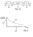
- FIG. 1A illustrates an example embodiment of a transmitter and a receiver.
- a transmitter 100 includes a transmitter input 104 and a transmitter output 108.
- the output 108 of the transmitter 100 connects to a channel 112.
- the channel 112 connects to an input 116 of a receiver 120.
- the receiver 120 includes a receiver output 124.
- the receiver output 124 may connect to a computing device, terminal, switch, router, network processing device, or any device configured to receive data over the channel 112.
- the transmitter 100 may comprise any device configured to transmit data from a first location to a second location.
- the receiver 120 may comprise any device configured to receive data transmitted from the first location to the second location. It is contemplated that a transmitter 100 and receiver 120 may be located at both ends of the channel 112 to enable transmission in both directions. In one embodiment the transmitter 100 and receiver 120 are located in a network interface card in a network terminal, such as a computer configured as part of a local area network.
- the channel 112 may comprise any type communication medium capable of transporting data between a first location and a second location.
- the channel 112 comprises twisted pair copper wire, such as is compatible with data transmission with certain existing Ethernet communication protocols.
- Any type channel 112 may be utilized with the method and apparatus described herein including but not limited to fiber optic, coaxial, non-twisted metallic conductors, or a wireless medium.
- a channel 112 connects a first transceiver 130 to a second transceiver 134. T he first transceiver 130 connects to the channel 112 via an interface 144.
- the interface 144 is configured to isolate the incoming from outgoing signals.
- the channel 112 may comprise numerous conductors and hence the interface 144 performs isolation and separates the conductors based on direction of data flow and based on connection to either of a receiver module 138 or a transmitter module 142.
- the receive module 138 and transmit module 142 may comprise any assembly of hardware, software, or both configured to operate in accordance with the principles described herein.
- the receive module 138 and transmit module 142 communicate with a processor 146.
- the processor 146 may include or communicate with memory 150.
- the memory 150 may comprise one or more of the following types of memory: RAM, ROM, hard disk drive, flash memory, or EPROM.
- the processor 146 may be configured to perform one or more calculations or signal analysis. In one embodiment the processor 146 is configured to execute machine readable code stored on the memory 150. The processor 146 may perform additional signal processing tasks as described below.
- the second transceiver 134 is configured similarly to the first transceiver 130.
- the second transceiver 134 comprises an interface 152 connected to a receiver module 156 and a transmitter module 160.
- the receiver module 156 and a transmitter module 160 communicate with a processor 164, which in turn connects to a memory 168. Operation occurs as described below in more detail.
- FIG. 2 an exemplary plot of the frequency response of a channel, such as channel 112 of Figure 1 .
- a plot of the channel's frequency response 200 is plotted against a vertical axis 204 representing a channel response magnitude while the horizontal axis 208 represents frequency.
- the channel frequency response is severely attenuated across the available bandwidth.
- Intersymbol interference limits the maximum useable bandwidth of a channel by limiting the rate at which pulses, bits, symbols, or signals may be transmitted across the channel. As a result of intersymbol interference, it may be impossible to decode a signal at the receiver, or, if decoding is possible, then an unacceptably high error rate may occur.
- the method and apparatus described herein overcomes the bandwidth limiting effects of intersymbol interference thereby allowing greater transmission rates through channels that cause intersymbol interference. While the method and apparatus described herein is capable of operation in numerous different environments and overcoming the signal distorting effects of any type channel, it is particularly well suited to overcome the effects of transmission through twisted pair copper because transmission through twisted pair copper experiences severe intersymbol interference.
- a data source 300 connects to a mapping module 304, which in turn connects to a precode filter 305.
- the data source 300 may comprise any source of data to be transmitted over a channel.
- the data source 300 comprises a processing or networking layer of a communication protocol.
- the data source 300 comprises a network processing device.
- the data arrives from application software executing on a computer.
- the mapping module 304 comprises hardware, software, or a combination of both configured to transform the received binary data into one or more symbols capable or representing one or more bits of binary data.
- One example mapping that may occur is pulse amplitude modulation (PAM) wherein the several bits of binary data are mapped into a single symbol.
- Another example of mapping comprises quadrature amplitude modulation (QAM).
- PAM pulse amplitude modulation
- QAM quadrature amplitude modulation
- mapping module 304 may incorporate forward error correction (FEC) coding.
- FEC forward error correction
- Examples of FEC coding comprise convolutional coding and trellis coding. It is contemplated that the method and apparatus described herein may be utilized with any form of error correction, or without error correction.
- the precode filter 308 connects to the output of the mapping module 304 and comprises a signal modification device configured to manipulate the signal to counter the distorting effects of the channel.
- the precode filter 308 may be configured as a digital filter having coefficient values set to achieve a desired level of signal modification.
- the precode filter 308 comprises a finite impulse response filter adapted to at least partially negate the distorting effects of a channel. Selection of precode filter coefficients is discussed below in greater detail.
- the output of the precode filter 308 connects to a digital to analog (D/A) converter 312 to transform the mapped signal to an analog format. Thereafter, the signal is provided to a line driver/amplifier 316.
- the line driver/amplifier 316 transforms the signal to a power level suitable for transmission over the channel. The degree or level of amplification may be dependant upon the power limits or specification as defined by a particular communication protocol, crosstalk and coupling concerns, and the distance to a receiver or a repeater.
- the output of the line driver/amplifier 316 connects to a transformer/hybrid 320.
- the transformer/hybrid 320 provides isolation between transmit and receive signals as well as the channel itself.
- the output of the transformer/hybrid 320 connects to a channel.
- FIG. 4 illustrates a block diagram of an example embodiment of a precode filter 400 embodied as a finite impulse response (FIR) filter.
- an input 404 connects to a delay register 408 that is configured to receive and delay for a clock cycle or other period.
- the input 404 also connects to a multiplier 412A having a multiplier value Po.
- the output of the multiplier 412A connects to a summing junction 424.
- the output of the register 408 connects to multiplier 412B having a multiplier value P 1 .
- the output of the multiplier 412B connects to the summing junction 424 to add the output of the multiplier 412B and the multiplier 412A.
- the output of the register 408 also connects to a register 416, the output of which connects to multiplier 412C.
- the output of the multiplier 412C connects to the summing junction 436, which also receives the output of summing junction 424.
- the filter 400 continues in this configuration until connecting to a register 432 that has an output connected to a multiplier 412D with a multiplier factor P N .
- the output of multiplier 412D connects to a summing junction 444 that also receives the output of the previous summing junction.
- This configuration is N+1 long with the elements of the filter controlling the modification or precoding that occurs on the signal.
- the multiplier values may comprise the filter coefficients. Hence, a signal is output from the filter having been modified based on the values of the multipliers 412.
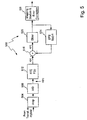
- FIG. 5 illustrates a block diagram of an example embodiment of a receiver. This is but one possible receiver configuration. It is contemplated that other receiver configurations may be enabled without departing from the scope of the invention.
- the receiver 500 comprises an amplifier 504 configured to receive a signal arriving over a channel.
- the amplifier 504 increases the power level or voltage of the received signal, which may have been attenuated by transmission through the channel.
- the amplified signal feeds into an analog to digital (A/D) converter 508, which in turn provides a digital signal, rx(n), to a feed forward equalizer (FFE) 512.
- the output of the FFE, x(n) connects to a summing junction 516.
- A/D analog to digital
- FFE feed forward equalizer
- the summing junction 516 also receives an input from a decision feedback equalizer (DFE) 524. In one embodiment the summing junction subtracts the DFE input from the FFE output.
- the summing junction 516 provides its output, s(n), to a decision device, such as a slicer 520.
- the slicer 520 comprises any device capable of analyzing a received signal at particular points in time and quantizing the received signal to two or more distinct values. In one embodiment the slicer operates in conjunction with PAM 10 mapping t o quantize its input to one of 10 values. I n one embodiment the slicer 520 analyzes the received signal's voltage level, after processing, to determine the symbol sent over the channel.
- the output of the slicer 520 may comprise binary data or mapped voltage levels.
- the slicer 520 provides it output to a de-mapping module 528 and as an input signal to the DFE 524. If the transmitter performed error correction encoding on the signal prior to transmission, then the de-mapping module 528 may perform error correction decoding on the received signal to decrease the bit error rate. The error correction processing, as part of the forward error correction, reduces the effective error rate of the data signal. Forward error correction may occur on binary data or symbols.
- the FFE 512 and the DFE 524 perform equalization on the received signal to compensate for the distorting effects of the channel.
- the DFE 524 receives and weights past values, which are subsequently subtracted, in the summing junction 516, from the arriving signal. It is contemplated that the FFE 512 and DFE 524 may possess coefficients, or other scaling values, associated with one or more taps or stages of the FFE and the DFE. The coefficient values are selected to achieve desired signal equalization to thereby negate, reverse, or reduce the effects of the channel. In one embodiment the FFE 512 and DFE 524 coefficient value are selected based on the principles described herein.
- the coefficient values of the FFE 512, DFE 524, and the precode filter are calculated and selected to counter the signal distorting effects of the channel while minimizing noise amplification and minimizing the undesirable effects of error propagation through the DFE feedback loop.
- Figure 6A illustrates an exemplary plot of an exemplary received pulse.
- the received signal is the superposition of many pulses scaled by the data symbol:
- a received pulse 604 is shown as a function of voltage represented on a vertical axis 608 and time on a horizontal axis 612.
- a main cursor 620 identifies a sampling point 616.
- the sampling point may be considered the point at which a slicer determines the values of the data symbols.
- Sample points arriving prior to the main cursor 620 are defined as pre-cursor points 624 while sample points arriving after the main cursor are defined as post-cursor points 628.
- DFE operation is directed primarily to post-cursor intersymbol interference mitigation while the FFE operation is directed to pre-cursor intersymbol interference mitigation.
- FFE operation it is desired to achieve FFE operation such that a pulse, received through the channel and after processing by the FFE would be monic and minimum phase, i.e. all the pre-cursor information is eliminated.
- FIG. 6B illustrates an exemplary plot of an exemplary received signal 670 with intersymbol interference.
- intersymbol interference signal samples 640 are shown in addition to the desired signal sample 616. It is contemplated that the intersymbol interference signal samples 640 may interfere, due to channel distortion, with the desired signal samples 616 to produce a sample 650 of the received signal 670. As can be understood, the desired sample 616 will combine with the interference samples 640 to create a signal having a reduced magnitude 650. While an extreme example, it can be understood that in the absence of channel equalization, the slicer, when presented with the reduced voltage magnitude 650, will result in an incorrect decision. This creates a symbol error and is particularly troublesome because, in certain mapping schemes, each symbol can equate to many binary bits. The method and apparatus described herein achieves equalization and overcomes these drawbacks.
- the variable C represents the coefficients of the equivalent channel, d represents data symbols and the variable n represents a sampling time. Accordingly, n is the current sampling time while n-1 represents a previous sampling time.
- the FFE is configured to eliminate the pre-cursor terms while the main cursor and K 3 post-cursor terms remain. Stated another way, the main cursor d n and the terms to the right of the main cursor are left to form the output of the FFE.
- coefficients are selected to overcome the drawbacks of the prior art based on a partial precoding method.
- precoding occurs for only a limited number of post-cursors and FFE processing and DFE processing also occurs at the receiver. Selection or calculation of the coefficients for the precoder, FFE, and DFE occur as described below. Based on the coefficient selection and the inclusion of a precoder, FFE, and DFE the pre and post cursor intersymbol interference is eliminated or reduced and error propagation is reduced to an acceptable level or eliminated. Moreover, the peak to average (PAR) value of the signal presented to the receiver is within acceptable limits and error propagation is minimized or eliminated.
- PAR peak to average
- the FFE may be represented as the coefficients of a polynomial.
- this resulting K th order polynomial may be factored into the minimum phase roots and the maximum phase roots.
- the minimum phase roots are defined as all roots where the absolute value of r k ⁇ 1 for all k and the maximum phase roots are defined as all roots where the absolute value of r k > 1 for all k.
- a trained FFE is a maximum phase type system.
- a trained DFE tends to be minimum phase. It follows that mixed phase systems include root values that have magnitude both greater than and less than 1.
- Figure 7 illustrates an operational flow diagram of an exemplary method of operation.
- the method described herein performs training and processing to establish precoder coefficients and equalizer coefficients for the FFE and the DFE.
- the precoder in the transmitter operates to reduce or eliminate the part of post-cursor interference which contributes most to error propagation while the FFE in the receiver operates to reduce or eliminate pre-cursor interference.
- the DFE in the receiver operates to eliminate residual post cursor interference.
- the length, i.e. the number of taps, and hence number of coefficients of the DFE is made to be greater than the number of coefficients in the precoder given by N+1.
- the D FE is configured with more taps than an associated precode filter. Hence there is a greater number of taps in the DFE than the number of post-cursors that are to be precoded by the precode filter.
- the initial coefficient values in a DFE have the largest influence on the DFE.
- the first N DFE taps are considered to have the greatest effect on the operation of the DFE output.
- an error by the slicer that is fed back to the DFE when the first N coefficients of the DFE are set to zero is less likely to propagate additional errors than a DFE with the first N coefficients set to non-zero values.
- setting the first N coefficients of the DFE to zero reduces the likelihood of additional errors in subsequent decisions by a slicer.
- the use of the precoder to effect the first N taps of the DFE filter is discussed below in more detail.
- Training comprises a process of filter coefficient calculation.
- the training occurs each time the receiver or transmitter is energized or activated.
- training occurs during design of the system and the filter coefficients are hardcoded.
- the FFE is trained as a mixed phase filter and not as the typical maximum phase filter. Stated another way, a training event occurs whereby the coefficients of the taps of the FFE are determined.
- the FFE is configured to include both minimum and maximum phase terms, and hence it is mixed phase.
- the training may comprise real time operation that occurs when a communication begins as part of an exchange of data between a transmitter and a receiver.
- a known or predetermined sequence may be utilized or a random or pseudorandom sequence may be utilized, such as would be required in the least mean square (LMS) algorithm for coefficient determination.
- LMS least mean square
- an assumption may be made that all devices will encounter a known channel. If such an assumption is made, then an estimate of an exemplary channel may be arrived at during a design state of the system and the equalizer system may be hardcoded or hardwired with these predetermined values. In such an embodiment the training process would not occur every time a communication session begins, but instead during device design or manufacture. Training may be achieved using hardware or software systems or a combination thereof. Processor or machine executable code may be stored in a memory and executed on a processor to determine the coefficient values. Hard coded logic, delays, summing junctions, multipliers or any other hardware may be utilized for training. It is contemplated that the method described herein may occur using computer program product comprising a computer useable medium having computer program logic recorded thereon, or hardware, or a combination of both.
- the DFE is trained such that the first N coefficients are forced to zero while the tail may assume non-zero values.
- the tail is defined as filter coefficient values other than the first N.
- the first N coefficient values are set to zero prior to training, and thereafter training occurs. In one embodiment this comprises executing any training processes, such as that described above to determine FFE coefficient values while concurrently setting the first N coefficients to a predetermined value. It is contemplated that in other embodiments the first N coefficients maybe set to a predetermined value other than zero.
- the FFE and DFE are trained simultaneously.
- N represents an arbitrary number selected based on the particular design parameters and desired filter/equalizer complexity. In one embodiment N is selected such that the value N is sufficient to reduce or eliminate catastrophic failure as a result of feedback of errors to the slicer. By setting the first N coefficients of the DFE to zero, the significance of the DFE in signal equalization is reduced and hence the chance of error propagation is reduced. In one embodiment Nisset to 4. In other embodiments the value of N may range from 1 to 50.
- the method and apparatus implements a precoder, having responsibility for precoding (equalizing) the effects of the first N post cursors that would have otherwise been equalized by the DFE. Further, there need not be a one-to-one correspondence between the number of DFE coefficients that are forced to zero and the level of precoding.
- the main tap of the FFE filter is adjusted or shifted by N cursor positions.
- the main cursor location is not the last tap, but N taps preceding the last tap.
- the FFE training results in FFE coefficients values that account for both post cursor interference and pre-cursor interference.
- the FFE is a mixed phase filter. Absent further equalization or coefficient adjustment, such as by use of a precode filter, the system, and in particular the FFE would undesirably enhance noise. This occurs because a mixed phase FFE enhances noise.
- the method performs spectral factorization on the coefficients of the trained FFE. This occurs at step 720.
- the roots are represented by the variable r' k .
- processing occurs to identify all the r' k values having magnitude of less than one. These are defined as the minimum phase roots. Any root finding algorithm maybe used to find the roots. The algorithm may be implemented in hardware, software or some combination of both. Step 720 also comprises identifying all the r k values that have magnitude greater than 1. These are defined as the maximum phase roots.
- P(z) representing the transmitter precoder function
- P z p 0 + p 1 ⁇ z - 1 + ... + p N ⁇ z - N
- This set of coefficient values ⁇ p ⁇ are, at a step 728, communicated back to the transmitter associated with the receiver. Then at a step 732, these coefficient values become the precoder coefficient values for the precoder located in the transmitter.
- the FFE coefficients determined by training at step 712, are subject to spectral factorization and the minimum phase roots are identified and formed into a polynomial.
- the coefficients of this polynomial are transmitted to the precode filter and serve as the precoder coefficient values. Hence, the precoder filter coefficients are established.
- the operation now identifies the maximum phase roots, i.e. the roots having magnitude greater than 1 for all k values. Any root finding algorithm maybe used to find the roots.
- the algorithm may be implemented as either hardware, software or some combination of both.
- F z f 0 + f 1 ⁇ z - 1 + ... + f M ⁇ z - M
- F'(z) (non-factored) differs from F(z) (factored and non-prime) in that F'(z) is a mixed phase filter which has yet to undergo spectral factorization while F(z) represent the FFE filter configured with the maximum phase roots of the factored polynomial resulting from the factorization of the coefficients of F'(z).
- the coefficients of this polynomial become the coefficients of the FFE filter in the receiver.
- the trained FFE coefficients from step 712 are thus replaced by the coefficients of the polynomial derived from the maximum phase roots after spectral factorization.
- communication using the receiver and transmitter pair may be enabled.
- the DFE coefficients and FFE coefficients are determined during the training process described above in conjunction with steps 712 and 716, with the first N coefficient values of the DFE set to zero or some other value.
- the precoder coefficients are determined to be the minimum phase roots of the factored polynomial derived from the trained FFE coefficients. This occurs at step 732.
- the FFE coefficients are set as the maximum phase roots of the factored polynomial derived from the trained FFE. This occurs at step 740.
- Data mode is defined to mean a time period when the transmitter/receiver pair operates to transmit data, such as data from a data source.
- Data mode is in contrast to training mode, handshake mode or start-up.
- Adaptation of the filter coefficients during data mode allows the filter to deal with, i.e. adapt, to changes in the channel that may occur over time. While it is assumed during the initial training process that the coefficients accurately equalize the channel, the values resulting from the initial training may be slightly incorrect or the channel transfer function m ay c hange over time.
- the first N coefficients may be maintained at zero and the remaining coefficients are adapted in real time during data mode. In another embodiment one or more of the first N coefficients may be modified. For FFE adaptation during data mode, the coefficients are adapted in real time. Alternatively, the FFE could be trained as a mixed phase filter to compensate for the fixed precoder which, in some embodiments, may not easily be adapted during data mode. It is contemplated that the precoder could be adapted during data mode via a side channel or in any other manner.
- TH precoding teaches away from the approach described herein by eliminating the DFE.
- TH precoding eliminates the use of the DFE in the receiver thereby eliminating any possibility of error propagation.
- TH precoding suffers from the disadvantages of lacking data mode adaptation. Lack of adaptation during data mode, results in a less effective equalizer because of the inability to adapt to changing channel conditions.
- TH precoding results in a transmitted signal having a large received PAR value.
- PAR is defined as peak to average value of a signal.
- a large PAR value results in a more challenging and expensive analog front end at the receiver.
- the analog to digital converter at the receiver may require more converter bits than with a signal having a smaller PAR value. This requirement limits the sampling rate of the converter and as a result limits its use in high speed applications.
- the received signal possesses a desirable, i.e. lower, PAR value.
- the FFE may be configured, during steps 736, 740, as a mixed phase system.
- step 712 and 716 would occur by training the FFE and DFE.
- the system factors the roots of the polynomial formed from the FFE coefficients and the precoder filter coefficients are set.
- the operation either during data mode or during training, may re-train the FFE and DFE with the precode filter in the loop, i.e. operating.
- the first N coefficient would be forced to zero during this re-training process.
- the FFE will become a mixed phase system.
- the FFE may introduce a minimal amount of noise enhancement, this embodiment reduces the complexity of the system and the training process while still providing desirable equalization and reducing error propagation. This embodiment also compensates for any inaccuracies that may occur during the estimation of the precoder coefficients.
- the FFE coefficients may be left as was determined at step 712, but appended with zeros (or some other value) to reduce the noise enhancement. Since, the partial ISI components that generate the postcursor components are being dealt with at the transmitter, it is possible to set the coefficients of the FFE that would otherwise equalize the pre-cursor components of the received signal to zero or some other value. Because one or more of these coefficients are set to zero or some other small value, the noise enhancement is reduced or eliminated. This reduces the complexity of the system and the training process while providing the equalization advantages discussed above.
Abstract
Description
- The invention relates to communication systems and in particular to a method and apparatus for channel equalization.
- Demand for high rate data transmission continues to increase in response to new service offerings and expanded communication network usage, such as for home and business tasks. For example, audio and video content is generally bandwidth intensive. In addition, many tasks are now commonly handled via a computer network, such as over the Internet, including ordering business supplies, exchanging documents, or information gathering. Moreover, bandwidth demand placed upon a companies local area network is increasing. Often networks are being burdened with more users and larger and more complex software applications. These applications are bandwidth intensive and the complex software applications create larger files. Although many networks are currently at bandwidth capacity additional demands are continually being placed on these networks.
- While there are numerous proposed solutions to alleviate network congestion by increasing network speeds, many of these proposed solutions involve adoption of a different communication standard or a different communication medium. While different communication standards (SONET, ATM) and different communication mediums (fiber optic cable, coaxial cable) may make it possible to increase data rates, the cost associated with migration is extremely prohibitive. For example, installation of an optical based network, i.e., 10G Ethernet on fiber or a SONET compatible network, to each computer in a local area network would require significant software and hardware upgrades on each end user's platform. The cost associated with cable installation as well as the retraining of service personnel alone is tremendous.
- Another proposed solution is to increase the transmission rate of existing networks. One widely deployed network standard is the version of Ethernet that utilizes twisted pairs of copper wire as its transmission medium. Although widely deployed and inexpensive to manufacture, twisted pair copper is bandwidth limited. As a result, data signals transmitted at very high rates in the gigabit per second range over the twisted pair copper, or other medium, are subject to significant levels of distortion. Upon reception, recovering the transmitted signal may be impossible due to this distortion.
- While it is possible to perform signal processing on the distorted signal, or even perform processing on the signal prior to transmission to counter the effects of the distortion, such prior art attempts have been insufficient to achieve very high data transmission rates with acceptable error rates.
- For example, certain prior art solutions propose utilizing a decision feedback equalizer (DFE) at the receiver. The DFE may operate in conjunction with a slicer, to determine a voltage level of the signal at a particular sampling time. The slicer output is fed back to the DFE as a feedback signal to aid in subsequent decisions. While the DFE with slicer feedback is capable of decreasing the error rate under certain conditions, it suffers from catastrophic failure when presented with a string of slicer errors as feedback to the DFE. Catastrophic failure is even more likely when error correction is adopted. This is not an acceptable solution and generally will not fall within the specifications set forth by most communication standards.
- As a result, there is a need for a method and apparatus capable of overcoming the data rate limiting effects of a channel.
- GI-HONG IM ET AL: "Performance of a Hybrid Decision Feedback Equalizer Structure for CAP-Based DSL Systems" IEEE TRANSACTIONS ON SIGNAL PROCESSING, IEEE SERVICE CENTER, NEW YORK, NY, US, vol. 49, no. 8, August 2001 (2001-08), ISSN: 1053-587X discloses hybrid-type decision feedback equaliser structures for high-speed digital transmission systems. A number of different embodiments are disclosed, each showing different precoding structures for various decision feedback equalizers. In a training period, the feedforward filter and the feedback filter in a receiver are adapted. The resulting coefficients of the feedback filter are then transmitted back to the transmitter over a reverse channel.
- EYUBOGLU M V: "Flexible precoding for V.fast (modem)" DATA TRANSMISSION - ADVANCES IN MODEM AND ISDN TECHNOLOGY AND APPLICATIONS, 1992., INTERNATIONAL CONFERENCE ON LONDON, UK, LONDON, UK, IEE UK, 1992. pages 13-18, ISBN: 0-85296-552-4 discloses flexible precoding for V.fast. A precoder and a precoding receiver are provided. The precoder utilises a feedback filter in combination with a slicer. The receiver utilises a feedback filter in combination with a Viterbi decoder and a further feedback filter and slicer. The same feedback filter coefficients are utilised in the prediction filter as are utilised in the decoder. The feedback filter coefficients are determined during training after a linear equaliser has been trained. The feedback coefficients are then transmitted back to the transmitter at the end of training.
-
US 6,356,555 discloses techniques for digital data transmission using orthogonal codes. In one embodiment a receiver is provided which receives data transmitted by a transmitter. The receiver utilises feedforward equalisers and decision feedback equalisers. These equalisers receive their adoptive tap coefficients from a least mean square calculation circuit. The least mean square circuit iteratively calculates the new tap coefficients and provides these to the equalisers. The final tap weight coefficients are sent to the precode equalisation filter in the transmitter. -
US 6,167,082 discloses adaptive equalisation with precoded systems. An embodiment of a typical digital communication system is shown. The communication system utilises a feedforward equalilser block, and a feedback loop. Two paths are shown, one for an in-phase and one for quadrature components. The feedforward equaliser aims to cancel the maximum phase response of the channel which results in precursor intersymbol interference, whilst the decision feedback equaliser seeks to cancel the minimum phase response of the channel which results in post-cursor intersymbol interference. Five different adaptation schemes are disclosed which may be utilised to inform a precoder of the need to update its coefficients. - The method and apparatus described herein overcomes the drawbacks of the prior art by providing a method and apparatus for signal processing to compensate for the effects of signal transmission through a channel. In one embodiment a transmitter is configured to communicate with a receiver via one or more communication channels. The receiver may be configured with a feedforward filter and a feedback filter while the transmitter is configured with a precode filter. Filter operation is controlled by coefficient values. Based on the coefficient calculation process described herein a method and apparatus for filtering is disclosed that overcomes the drawbacks of the prior art. In an example environment of a communication system, the method and apparatus for filtering described herein is utilised for equalization to compensate for the effects of intersymbol interference.
- In one aspect of the present invention, there is provided a method as claimed in
claim 1. - It is contemplated that the step of transmitting may comprise transmitting the minimum phase coefficients over one or more twisted pair conductors to a precode filter in a transmitter. The processing may comprise performing spectral factorization and forming a polynomial to obtain the minimum phase coefficients and the maximum phase coefficients.
- A method for equalizing a signal is also disclosed that comprises receiving a signal transmitted through a communication channel and performing a first equalization process on the signal utilizing a first equalizer having maximum phase coefficient values.
- Thereafter, performing a second equalization process on the signal utilizing a second equalizer having second equalizer coefficient values wherein the first equalization process and the second equalization process reduce the distorting effects of transmission through the channel.
- Moreover, performing a second equalization process may further include providing a feedback signal to a decision device.
- In another aspect of the present invention there is provided a system for channel equalization as claimed in claim 12.
- In one embodiment the predetermined value comprises zero.
- The first filter coefficient values, second filter coefficient values, and precode filter coefficient values may be determined during a training process and one aspect of the training process may comprise spectral factorization.
- In yet another embodiment a system is disclosed comprising a first transceiver comprising a data source interface configured to receive data from a data source, a precode filter configured to equalize the data to at least partially account for transmission through a channel, a digital to analog converter configured to convert the data to a first analog signal, a line driver configured to adjust the power of the first analog signal for transmission over a channel, and a receiver configured to receive data from a second transceiver.
- This system may also include a second transceiver with an amplifier configured to receive a second analog signal from the channel such that the second analog signal comprises a distorted version of the first analog signal. The system may also include the following aspects: an analog to digital converter configured to convert the second analog signal to data, a first filter configured to process the data to at least partially reverse the effects of transmission through the channel, a second filter configured to process the data to at least partially reverse the effects of transmission through the channel, a decision device configured to quantize portions of the data into two or more distinct values, and a transmitter configured to transmit precode filter coefficient data to the precode filter in the first transceiver.
- In another variation the second filter comprises a feedback filter having greater than N coefficients and the first N coefficients are set to zero such that N comprises an integer value having magnitude of less than 20.
- In another embodiment the method and apparatus disclosed is embodied as a computer program product comprising a computer useable medium as claimed in claim 18.
- It is contemplated that the computer program product may be located in a communication receiver or a transmitter.
- Other systems, methods, features and advantages of the invention will be or will become apparent to one with skill in the art upon examination of the following figures and detailed description. It is intended that all such additional systems, methods, features and advantages be included within this description, be within the scope of the invention, and be protected by the accompanying claims.
- The components in the figures are not necessarily to scale, emphasis instead being placed upon illustrating the principles of the invention. In the figures, like reference numerals designate corresponding parts throughout the different views.
-
Figure 1A illustrates a block diagram of an exemplary receiver and transmitter. -
Figure 1 B illustrates a block diagram of an exemplary receiver-transmitter pair. -
Figure 2 illustrates an exemplary channel frequency response. -
Figure 3 illustrates an exemplary block diagram of an example embodiment of a transmitter. -
Figure 4 illustrates a block diagram of an example embodiment of a precode filter embodied as a finite impulse response filter. -
Figure 5 illustrates a block diagram of an example embodiment of a receiver. -
Figure 6A illustrates an exemplary plot of a received signal pulse. -
Figure 6B illustrates an exemplary plot of a received signal containing intersymbol interference components. -
Figure 7 illustrates an operational flow diagram of an example method of operation. -
Figure 1A illustrates an example embodiment of a transmitter and a receiver. As shown, atransmitter 100 includes atransmitter input 104 and atransmitter output 108. Theoutput 108 of thetransmitter 100 connects to achannel 112. Thechannel 112 connects to aninput 116 of areceiver 120. Thereceiver 120 includes areceiver output 124. Thereceiver output 124 may connect to a computing device, terminal, switch, router, network processing device, or any device configured to receive data over thechannel 112. - The
transmitter 100 may comprise any device configured to transmit data from a first location to a second location. Likewise, thereceiver 120 may comprise any device configured to receive data transmitted from the first location to the second location. It is contemplated that atransmitter 100 andreceiver 120 may be located at both ends of thechannel 112 to enable transmission in both directions. In one embodiment thetransmitter 100 andreceiver 120 are located in a network interface card in a network terminal, such as a computer configured as part of a local area network. - The
channel 112 may comprise any type communication medium capable of transporting data between a first location and a second location. In one embodiment thechannel 112 comprises twisted pair copper wire, such as is compatible with data transmission with certain existing Ethernet communication protocols. Anytype channel 112 may be utilized with the method and apparatus described herein including but not limited to fiber optic, coaxial, non-twisted metallic conductors, or a wireless medium. - In reference to
Figure 1B , a block diagram of a receiver/transmitter pair is shown. Achannel 112 connects afirst transceiver 130 to asecond transceiver 134. T he first transceiver 130 connects to thechannel 112 via aninterface 144. Theinterface 144 is configured to isolate the incoming from outgoing signals. In another embodiment thechannel 112 may comprise numerous conductors and hence theinterface 144 performs isolation and separates the conductors based on direction of data flow and based on connection to either of areceiver module 138 or atransmitter module 142. The receivemodule 138 and transmitmodule 142 may comprise any assembly of hardware, software, or both configured to operate in accordance with the principles described herein. - The receive
module 138 and transmitmodule 142 communicate with aprocessor 146. Theprocessor 146 may include or communicate withmemory 150. Thememory 150 may comprise one or more of the following types of memory: RAM, ROM, hard disk drive, flash memory, or EPROM. Theprocessor 146 may be configured to perform one or more calculations or signal analysis. In one embodiment theprocessor 146 is configured to execute machine readable code stored on thememory 150. Theprocessor 146 may perform additional signal processing tasks as described below. - The
second transceiver 134 is configured similarly to thefirst transceiver 130. Thesecond transceiver 134 comprises aninterface 152 connected to areceiver module 156 and atransmitter module 160. Thereceiver module 156 and atransmitter module 160 communicate with aprocessor 164, which in turn connects to amemory 168. Operation occurs as described below in more detail. - Turning to
Figure 2 , an exemplary plot of the frequency response of a channel, such aschannel 112 ofFigure 1 . A plot of the channel'sfrequency response 200 is plotted against avertical axis 204 representing a channel response magnitude while thehorizontal axis 208 represents frequency. As can be seen, the channel frequency response is severely attenuated across the available bandwidth. - This will result in a received signal having experienced interference from adjacent pulses. This is often referred to as intersymbol interference or ISI. Intersymbol interference limits the maximum useable bandwidth of a channel by limiting the rate at which pulses, bits, symbols, or signals may be transmitted across the channel. As a result of intersymbol interference, it may be impossible to decode a signal at the receiver, or, if decoding is possible, then an unacceptably high error rate may occur.
- The method and apparatus described herein overcomes the bandwidth limiting effects of intersymbol interference thereby allowing greater transmission rates through channels that cause intersymbol interference. While the method and apparatus described herein is capable of operation in numerous different environments and overcoming the signal distorting effects of any type channel, it is particularly well suited to overcome the effects of transmission through twisted pair copper because transmission through twisted pair copper experiences severe intersymbol interference.
- In reference to
Figure 3 , an exemplary block diagram of an example embodiment of a transmitter is shown. This is but one exemplary embodiment of a transmitter. It is contemplated that other configurations may be embodied by one of ordinary skill in the art. In the exemplary configuration ofFigure 3 , adata source 300 connects to amapping module 304, which in turn connects to a precode filter 305. - The
data source 300 may comprise any source of data to be transmitted over a channel. In one embodiment thedata source 300 comprises a processing or networking layer of a communication protocol. In one embodiment thedata source 300 comprises a network processing device. In one embodiment the data arrives from application software executing on a computer. - The
mapping module 304 comprises hardware, software, or a combination of both configured to transform the received binary data into one or more symbols capable or representing one or more bits of binary data. One example mapping that may occur is pulse amplitude modulation (PAM) wherein the several bits of binary data are mapped into a single symbol. Another example of mapping comprises quadrature amplitude modulation (QAM). Through mapping, transmission of a single symbol achieves transmission of several bits of information thereby increasing data transfer rates. - In addition to mapping, the
mapping module 304 may incorporate forward error correction (FEC) coding. Examples of FEC coding comprise convolutional coding and trellis coding. It is contemplated that the method and apparatus described herein may be utilized with any form of error correction, or without error correction. - The
precode filter 308, which discussed below in greater detail, connects to the output of themapping module 304 and comprises a signal modification device configured to manipulate the signal to counter the distorting effects of the channel. Theprecode filter 308 may be configured as a digital filter having coefficient values set to achieve a desired level of signal modification. In one embodiment theprecode filter 308 comprises a finite impulse response filter adapted to at least partially negate the distorting effects of a channel. Selection of precode filter coefficients is discussed below in greater detail. - The output of the
precode filter 308 connects to a digital to analog (D/A)converter 312 to transform the mapped signal to an analog format. Thereafter, the signal is provided to a line driver/amplifier 316. The line driver/amplifier 316 transforms the signal to a power level suitable for transmission over the channel. The degree or level of amplification may be dependant upon the power limits or specification as defined by a particular communication protocol, crosstalk and coupling concerns, and the distance to a receiver or a repeater. The output of the line driver/amplifier 316 connects to a transformer/hybrid 320. The transformer/hybrid 320 provides isolation between transmit and receive signals as well as the channel itself. The output of the transformer/hybrid 320 connects to a channel. -
Figure 4 illustrates a block diagram of an example embodiment of aprecode filter 400 embodied as a finite impulse response (FIR) filter. As shown inFigure 4 , aninput 404 connects to adelay register 408 that is configured to receive and delay for a clock cycle or other period. Theinput 404 also connects to amultiplier 412A having a multiplier value Po. The output of themultiplier 412A connects to a summingjunction 424. - The output of the
register 408 connects tomultiplier 412B having a multiplier value P1. The output of themultiplier 412B connects to the summingjunction 424 to add the output of themultiplier 412B and themultiplier 412A. The output of theregister 408 also connects to aregister 416, the output of which connects tomultiplier 412C. The output of themultiplier 412C connects to the summingjunction 436, which also receives the output of summingjunction 424. Thefilter 400 continues in this configuration until connecting to aregister 432 that has an output connected to amultiplier 412D with a multiplier factor PN. The output ofmultiplier 412D connects to a summingjunction 444 that also receives the output of the previous summing junction. - This configuration is N+1 long with the elements of the filter controlling the modification or precoding that occurs on the signal. As a signal propagates through the
filter 400 it is affected by the multiplier values of the multipliers 412. In one embodiment, the multiplier values may comprise the filter coefficients. Hence, a signal is output from the filter having been modified based on the values of the multipliers 412. -
Figure 5 illustrates a block diagram of an example embodiment of a receiver. This is but one possible receiver configuration. It is contemplated that other receiver configurations may be enabled without departing from the scope of the invention. As shown thereceiver 500 comprises anamplifier 504 configured to receive a signal arriving over a channel. Theamplifier 504 increases the power level or voltage of the received signal, which may have been attenuated by transmission through the channel. The amplified signal feeds into an analog to digital (A/D)converter 508, which in turn provides a digital signal, rx(n), to a feed forward equalizer (FFE) 512. The output of the FFE, x(n), connects to a summingjunction 516. It is contemplated that one of ordinary skill in the art is capable of FFE construction and familiar with basic FFE operation. Accordingly the basic principles of FFE operation are not discussed in detail herein beyond that associated with the new and distinctive features of the invention. It is further contemplated that other filter or equalizer structures, other than an FFE, may be utilized without departing from the scope of the invention. - The summing
junction 516 also receives an input from a decision feedback equalizer (DFE) 524. In one embodiment the summing junction subtracts the DFE input from the FFE output. The summingjunction 516 provides its output, s(n), to a decision device, such as aslicer 520. Theslicer 520 comprises any device capable of analyzing a received signal at particular points in time and quantizing the received signal to two or more distinct values. In one embodiment the slicer operates in conjunction with PAM 10 mapping t o quantize its input to one of 10 values. I n one embodiment theslicer 520 analyzes the received signal's voltage level, after processing, to determine the symbol sent over the channel. The output of theslicer 520 may comprise binary data or mapped voltage levels. - The
slicer 520 provides it output to ade-mapping module 528 and as an input signal to theDFE 524. If the transmitter performed error correction encoding on the signal prior to transmission, then thede-mapping module 528 may perform error correction decoding on the received signal to decrease the bit error rate. The error correction processing, as part of the forward error correction, reduces the effective error rate of the data signal. Forward error correction may occur on binary data or symbols. - It is contemplated that one of ordinary skill in the art is capable of
DFE 524 construction and familiar with basic DFE operation. Accordingly the basic principles of DFE operation are not discussed in great detail herein beyond that associated with the new and distinctive features of the invention. It is further contemplated that other filter or equalizer structures, other than anFFE 512 orDFE 524 may be utilized without departing from the scope of the invention. - The
FFE 512 and theDFE 524 perform equalization on the received signal to compensate for the distorting effects of the channel. TheDFE 524, as part of the feedback, receives and weights past values, which are subsequently subtracted, in the summingjunction 516, from the arriving signal. It is contemplated that theFFE 512 andDFE 524 may possess coefficients, or other scaling values, associated with one or more taps or stages of the FFE and the DFE. The coefficient values are selected to achieve desired signal equalization to thereby negate, reverse, or reduce the effects of the channel. In one embodiment theFFE 512 andDFE 524 coefficient value are selected based on the principles described herein. - As an advantage of the method and apparatus described herein the coefficient values of the
FFE 512,DFE 524, and the precode filter (element 308,Figure 3 ) are calculated and selected to counter the signal distorting effects of the channel while minimizing noise amplification and minimizing the undesirable effects of error propagation through the DFE feedback loop. Through these desirable properties data communication is enabled at rates here before unattainable over certain channels and utilizing the components described herein. Moreover, complexity of all system components is capable of being realized with existing integrated circuit processes and construction. Similarly, the complexity of the processing is capable of being performed within time limits available during high speed data communication. - A discussion regarding coefficient calculation is now provided. It should be noted that although specified as particular filter configurations for purposes of discussion, it is contemplated that any type filter or signal modification device may replace the DFE, the FFE, or the precode filter.
-
Figure 6A illustrates an exemplary plot of an exemplary received pulse. The received signal is the superposition of many pulses scaled by the data symbol: As shown, a receivedpulse 604 is shown as a function of voltage represented on avertical axis 608 and time on ahorizontal axis 612. Amain cursor 620 identifies asampling point 616. The sampling point may be considered the point at which a slicer determines the values of the data symbols. Sample points arriving prior to themain cursor 620 are defined aspre-cursor points 624 while sample points arriving after the main cursor are defined aspost-cursor points 628. In one embodiment, DFE operation is directed primarily to post-cursor intersymbol interference mitigation while the FFE operation is directed to pre-cursor intersymbol interference mitigation. In one embodiment it is desired to achieve FFE operation such that a pulse, received through the channel and after processing by the FFE would be monic and minimum phase, i.e. all the pre-cursor information is eliminated. -
Figure 6B illustrates an exemplary plot of an exemplary receivedsignal 670 with intersymbol interference. As compared toFigure 6A , like elements are labeled with identical reference numerals. For purposes of discussion, intersymbolinterference signal samples 640 are shown in addition to the desiredsignal sample 616. It is contemplated that the intersymbolinterference signal samples 640 may interfere, due to channel distortion, with the desiredsignal samples 616 to produce asample 650 of the receivedsignal 670. As can be understood, the desiredsample 616 will combine with theinterference samples 640 to create a signal having a reducedmagnitude 650. While an extreme example, it can be understood that in the absence of channel equalization, the slicer, when presented with the reducedvoltage magnitude 650, will result in an incorrect decision. This creates a symbol error and is particularly troublesome because, in certain mapping schemes, each symbol can equate to many binary bits. The method and apparatus described herein achieves equalization and overcomes these drawbacks. - By way of introduction and referring to
Figure 5 , a receiver output, prior to equalization, can be defined by the convolution;
which can be expanded to;
where the value C0dn represent the main cursor and the terms prior to C0dn represent pre-cursor terms while the terms after C0dn represent post-cursor terms. The variable C represents the coefficients of the equivalent channel, d represents data symbols and the variable n represents a sampling time. Accordingly, n is the current sampling time while n-1 represents a previous sampling time. - Similarly, the FFE output may be represented as;

and this representation may be expanded as;
- As can be seen, the FFE is configured to eliminate the pre-cursor terms while the main cursor and K3 post-cursor terms remain. Stated another way, the main cursor dn and the terms to the right of the main cursor are left to form the output of the FFE.
- If the DFE coefficients are chosen to be {bn}, then the slicer input can be defined as;

where d̂ is an estimate and may be equal to d. - Thus for correctly fedback symbol decisions when d̂ equals d, then;

provided K4 is greater than or equal to K3 and
when K4 is less than K3, there will be some residual uncancelled post cursor ISI. These equations may be considered to define the signals and their processing within the receiver. - As discussed above, if incorrect decisions are made by the slicer, these incorrect decisions are fed back into the DFE and error propagation occurs. As a result of the feedback, the errors may build upon themselves. In embodiments having forward error correction processing subsequent to the DFE, this error propagation may result in long strings of errors being presented to the forward error correction processing. The problems are compounded since the slicer operates without the coding gain provided by the forward error correction. Hence the slicer error rate is higher thereby increasing the likelihood of error propagation. Consequently, the communication session must be closed and restarted. This is generally undesirable.
- In one embodiment of the method and apparatus described herein, coefficients are selected to overcome the drawbacks of the prior art based on a partial precoding method. In summary, precoding occurs for only a limited number of post-cursors and FFE processing and DFE processing also occurs at the receiver. Selection or calculation of the coefficients for the precoder, FFE, and DFE occur as described below. Based on the coefficient selection and the inclusion of a precoder, FFE, and DFE the pre and post cursor intersymbol interference is eliminated or reduced and error propagation is reduced to an acceptable level or eliminated. Moreover, the peak to average (PAR) value of the signal presented to the receiver is within acceptable limits and error propagation is minimized or eliminated.
- As described above, the FFE may be represented as the coefficients of a polynomial. Thus, the polynomial may be represented as;

which may be factored in product form as;
where r is a function of the f values and are the roots of the polynomial. In an expanded form this may be considered a Kth order polynomial. It should be further understood that this resulting Kth order polynomial may be factored into the minimum phase roots and the maximum phase roots. The minimum phase roots are defined as all roots where the absolute value of rk < 1 for all k and the maximum phase roots are defined as all roots where the absolute value of rk > 1 for all k. The case with equality to one can not occur in practice with channels having finite frequency responses. In general, a trained FFE is a maximum phase type system. In general, a trained DFE tends to be minimum phase. It follows that mixed phase systems include root values that have magnitude both greater than and less than 1. Working from this understanding regarding a trained FFE filter, the discussion of a method of training, as contemplated by the invention, may occur. - Next, to achieve the benefits of the equalization and precoding described herein, reference is made to
Figure 7. Figure 7 illustrates an operational flow diagram of an exemplary method of operation. In general the method described herein performs training and processing to establish precoder coefficients and equalizer coefficients for the FFE and the DFE. As a result, the precoder in the transmitter operates to reduce or eliminate the part of post-cursor interference which contributes most to error propagation while the FFE in the receiver operates to reduce or eliminate pre-cursor interference. The DFE in the receiver operates to eliminate residual post cursor interference. In one embodiment the length, i.e. the number of taps, and hence number of coefficients of the DFE is made to be greater than the number of coefficients in the precoder given by N+1. Thus, at astep 704 the D FE is configured with more taps than an associated precode filter. Hence there is a greater number of taps in the DFE than the number of post-cursors that are to be precoded by the precode filter. - It should also be noted that the initial coefficient values in a DFE have the largest influence on the DFE. Hence, the first N DFE taps are considered to have the greatest effect on the operation of the DFE output. Hence an error by the slicer that is fed back to the DFE when the first N coefficients of the DFE are set to zero is less likely to propagate additional errors than a DFE with the first N coefficients set to non-zero values. Thus, setting the first N coefficients of the DFE to zero reduces the likelihood of additional errors in subsequent decisions by a slicer. The use of the precoder to effect the first N taps of the DFE filter is discussed below in more detail.
- Next, at a
step 708, a training process is initiated. Training comprises a process of filter coefficient calculation. In one embodiment the training occurs each time the receiver or transmitter is energized or activated. In another embodiment training occurs during design of the system and the filter coefficients are hardcoded. At astep 712, the FFE is trained as a mixed phase filter and not as the typical maximum phase filter. Stated another way, a training event occurs whereby the coefficients of the taps of the FFE are determined. As a parameter, the FFE is configured to include both minimum and maximum phase terms, and hence it is mixed phase. It is contemplated that the training may comprise real time operation that occurs when a communication begins as part of an exchange of data between a transmitter and a receiver. A known or predetermined sequence may be utilized or a random or pseudorandom sequence may be utilized, such as would be required in the least mean square (LMS) algorithm for coefficient determination. - It is further contemplated that an assumption may be made that all devices will encounter a known channel. If such an assumption is made, then an estimate of an exemplary channel may be arrived at during a design state of the system and the equalizer system may be hardcoded or hardwired with these predetermined values. In such an embodiment the training process would not occur every time a communication session begins, but instead during device design or manufacture. Training may be achieved using hardware or software systems or a combination thereof. Processor or machine executable code may be stored in a memory and executed on a processor to determine the coefficient values. Hard coded logic, delays, summing junctions, multipliers or any other hardware may be utilized for training. It is contemplated that the method described herein may occur using computer program product comprising a computer useable medium having computer program logic recorded thereon, or hardware, or a combination of both.
- Concurrently or thereafter at a
step 716, the DFE is trained such that the first N coefficients are forced to zero while the tail may assume non-zero values. The tail is defined as filter coefficient values other than the first N. In one embodiment, the first N coefficient values are set to zero prior to training, and thereafter training occurs. In one embodiment this comprises executing any training processes, such as that described above to determine FFE coefficient values while concurrently setting the first N coefficients to a predetermined value. It is contemplated that in other embodiments the first N coefficients maybe set to a predetermined value other than zero. In one embodiment the FFE and DFE are trained simultaneously. - The term N represents an arbitrary number selected based on the particular design parameters and desired filter/equalizer complexity. In one embodiment N is selected such that the value N is sufficient to reduce or eliminate catastrophic failure as a result of feedback of errors to the slicer. By setting the first N coefficients of the DFE to zero, the significance of the DFE in signal equalization is reduced and hence the chance of error propagation is reduced. In one embodiment Nisset to 4. In other embodiments the value of N may range from 1 to 50.
- To account for the first N coefficients being set to zero or some other predetermined value, the method and apparatus implements a precoder, having responsibility for precoding (equalizing) the effects of the first N post cursors that would have otherwise been equalized by the DFE. Further, there need not be a one-to-one correspondence between the number of DFE coefficients that are forced to zero and the level of precoding.
- As a result of the first N coefficients of the DFE being set to zero during training and the FFE filter being concurrently trained, the main tap of the FFE filter is adjusted or shifted by N cursor positions. Stated another way and in the exemplary case of a tap delay line configuration, the main cursor location is not the last tap, but N taps preceding the last tap.
- At this stage in the initial coefficient calculation process, precoding is not present and due to the first N DFE coefficients being set to zero, the FFE training results in FFE coefficients values that account for both post cursor interference and pre-cursor interference. Hence the FFE is a mixed phase filter. Absent further equalization or coefficient adjustment, such as by use of a precode filter, the system, and in particular the FFE would undesirably enhance noise. This occurs because a mixed phase FFE enhances noise.
- To overcome the noise enhancement effect, the method performs spectral factorization on the coefficients of the trained FFE. This occurs at
step 720. The roots of the mixed phase FFE (F') may be represented as;
- From this equation, the roots are represented by the variable r'k. As part of
step 720 processing occurs to identify all the r'k values having magnitude of less than one. These are defined as the minimum phase roots. Any root finding algorithm maybe used to find the roots. The algorithm may be implemented in hardware, software or some combination of both. Step 720 also comprises identifying all the rk values that have magnitude greater than 1. These are defined as the maximum phase roots. - For the minimum phase roots, P(z), representing the transmitter precoder function, may be represented in factored form;

which may be expanded into a polynomial in z, atstep 724, as shown below, where {p} equals a coefficient value and z-1 represents the unit of delay in a tap delay line filter.
- This set of coefficient values {p} are, at a
step 728, communicated back to the transmitter associated with the receiver. Then at astep 732, these coefficient values become the precoder coefficient values for the precoder located in the transmitter. - In summary of steps 720 - 732, the FFE coefficients, determined by training at
step 712, are subject to spectral factorization and the minimum phase roots are identified and formed into a polynomial. The coefficients of this polynomial are transmitted to the precode filter and serve as the precoder coefficient values. Hence, the precoder filter coefficients are established. - Next or concurrently, it is desired to determine the final FFE coefficients. At
previous step 720, spectral factorization was performed on the trained FFE coefficients. In contrast to identifying the minimum phase roots, which were used to determine the precoder filter coefficients, the operation now identifies the maximum phase roots, i.e. the roots having magnitude greater than 1 for all k values. Any root finding algorithm maybe used to find the roots. The algorithm may be implemented as either hardware, software or some combination of both. These roots may be represented as;
which may be expanded into a polynomial in z, atstep 736, as shown below, where f represents a coefficient value and z-1 represents a unit of delay in the tap delay line filter.
- F'(z) (non-factored) differs from F(z) (factored and non-prime) in that F'(z) is a mixed phase filter which has yet to undergo spectral factorization while F(z) represent the FFE filter configured with the maximum phase roots of the factored polynomial resulting from the factorization of the coefficients of F'(z).
- At a
step 740, the coefficients of this polynomial become the coefficients of the FFE filter in the receiver. The trained FFE coefficients fromstep 712 are thus replaced by the coefficients of the polynomial derived from the maximum phase roots after spectral factorization. Thereafter, at astep 744, communication using the receiver and transmitter pair may be enabled. - Hence, in summary of one embodiment, the DFE coefficients and FFE coefficients are determined during the training process described above in conjunction with
steps step 732. Finally, the FFE coefficients are set as the maximum phase roots of the factored polynomial derived from the trained FFE. This occurs atstep 740. - One advantage of the method and apparatus described herein is that in one embodiment or variation the DFE or other filter may be made to adapt during operation in data mode. Data mode is defined to mean a time period when the transmitter/receiver pair operates to transmit data, such as data from a data source. Data mode is in contrast to training mode, handshake mode or start-up. Adaptation of the filter coefficients during data mode allows the filter to deal with, i.e. adapt, to changes in the channel that may occur over time. While it is assumed during the initial training process that the coefficients accurately equalize the channel, the values resulting from the initial training may be slightly incorrect or the channel transfer function m ay c hange over time. F or DFE adaptation during data mode, the first N coefficients may be maintained at zero and the remaining coefficients are adapted in real time during data mode. In another embodiment one or more of the first N coefficients may be modified. For FFE adaptation during data mode, the coefficients are adapted in real time. Alternatively, the FFE could be trained as a mixed phase filter to compensate for the fixed precoder which, in some embodiments, may not easily be adapted during data mode. It is contemplated that the precoder could be adapted during data mode via a side channel or in any other manner.
- Another advantage of the method and apparatus described herein is evident in comparison to Tomlinson-Harashima type precoding (TH precoding). TH precoding teaches away from the approach described herein by eliminating the DFE. TH precoding eliminates the use of the DFE in the receiver thereby eliminating any possibility of error propagation. However, TH precoding suffers from the disadvantages of lacking data mode adaptation. Lack of adaptation during data mode, results in a less effective equalizer because of the inability to adapt to changing channel conditions.
- Further TH precoding results in a transmitted signal having a large received PAR value. PAR is defined as peak to average value of a signal. A large PAR value results in a more challenging and expensive analog front end at the receiver. As a result of a large PAR value of a received signal, the analog to digital converter at the receiver may require more converter bits than with a signal having a smaller PAR value. This requirement limits the sampling rate of the converter and as a result limits its use in high speed applications. With the method and apparatus described herein, the received signal possesses a desirable, i.e. lower, PAR value.
- In an alternative embodiment, the FFE may be configured, during
steps step step 720, the system factors the roots of the polynomial formed from the FFE coefficients and the precoder filter coefficients are set. Instead of using the maximum phase roots of F'(z) as the final FFE coefficients as contemplated bystep 736, the operation, either during data mode or during training, may re-train the FFE and DFE with the precode filter in the loop, i.e. operating. In one embodiment, the first N coefficient would be forced to zero during this re-training process. As a result, the FFE will become a mixed phase system. Although the FFE may introduce a minimal amount of noise enhancement, this embodiment reduces the complexity of the system and the training process while still providing desirable equalization and reducing error propagation. This embodiment also compensates for any inaccuracies that may occur during the estimation of the precoder coefficients. - In another alternative embodiment, the FFE coefficients may be left as was determined at
step 712, but appended with zeros (or some other value) to reduce the noise enhancement. Since, the partial ISI components that generate the postcursor components are being dealt with at the transmitter, it is possible to set the coefficients of the FFE that would otherwise equalize the pre-cursor components of the received signal to zero or some other value. Because one or more of these coefficients are set to zero or some other small value, the noise enhancement is reduced or eliminated. This reduces the complexity of the system and the training process while providing the equalization advantages discussed above. - While various embodiments of the invention have been described, it will be apparent to those of ordinary skill in the art that many more embodiments and implementations are possible that are within the scope of this invention.
Claims (19)
- A method for filter coefficient selection in a receiver-transmitter pair comprising:training (708, 712, 716) a first filter and a second filter to determine first filter coefficients and second filter coefficients such that the first filter and the second filter have a transfer function inverse to that of a channel (112), the first filter and the second filter being located in a receiver (120) and a third filter being located in a transmitter (100), the first filter comprising a feedforward filter (512), the second filter comprising a feedback filter (524), and the third filter comprising a precode filter (308; 400), characterized by that during the training at least one second filter coefficient is forced to a predetermined value;processing (720, 724) the first filter coefficients to isolate minimum phase coefficients and maximum phase coefficients:transmitting (728) the minimum phase coefficients to the third filter;establishing (732) coefficients of the third filter based on the minimum phase coefficients; andsetting (740) the first filter coefficients based on the maximum phase coefficients.
- The method of Claim 1, wherein transmitting comprises transmitting the minimum phase coefficients over one or more twisted pair conductors to the precode filter in the transmitter.
- The method of Claim 1, wherein processing comprises performing spectral factorization.
- The method of Claim 3, wherein processing further comprises forming a polynomial to obtain the minimum phase coefficients and the maximum phase coefficients.
- The method of Claim 1, wherein the at least one second filter coefficient that is forced to a predetermined value comprises four second filter coefficients that are forced to zero.
- The method of Claim 5, wherein the third filter comprises a five tap precode filter.
- The method of any one of claims 1 to 6 comprising:receiving a signal transmitted through a communication channel;performing a first equalization process on the signal utilizing the first filter having the maximum phase coefficients; andperforming a second equalization process on the signal utilizing the second filter having the second filter coefficients:wherein the first equalization process and the second equalization process reduce the effects of transmission through the channel.
- The method of Claim 7, wherein the at least one of the second filter coefficient comprises the first four second filter coefficients and wherein the predetermined value comprises a zero value.
- The method of Claim 7, further including precoding the signal prior to transmission using the precode filter having coefficients that are based on minimum phase coefficients generated by a training process of the second filter.
- The method of Claim 7, wherein at least one of the first five second filter coefficients are set to zero.
- The method of Claim 7, wherein performing a second equalization process further includes providing a feedback signal to a decision device (520).
- A system for channel equalization comprising:a first filter configured to utilize one or more first filter coefficients;a second filter having two or more second filter coefficients;a precode filter (308; 400) having one or more precode filter coefficients, wherein the first filter and the second filter are located in a receiver (120) and the precode filter is located in a transmitter (100), and wherein the first filter comprises a feed forward filter and the second filter comprises a feedback filter:a processor configured to calculate first filter coefficients and second filter coefficients such that the first filter and the second filter have a transfer function inverse to that of a channel (112) characterized by that during the calculation at least one second filter coefficients is forced to a predetermined value, the first filter coefficients ore processed to isolate minimum phase coefficients and maximum phase coefficients, the first filter coefficients are set based on the maximum phase coefficients and the precode filter coefficients are based on the minimum phase coefficients transmitted to the precode filter.
- The system of claim 12, wherein the first filter comprises a maximum phase filter and the precode filter comprises a minimum phase filter.
- The system of Claim 13, wherein the predetermined value comprises zero.
- The system of Claim 13, wherein the first filter, second filter end precode filter coefficient values ore determined during a training process and one aspect of the training process comprises spectral factorization.
- The system of claim 12, comprising:a first transceiver comprising:a data source interface configured to receive data from a data source (300);the precede filter configured to equalize the data to at least partially account for transmission through the channel;a digital to analog converter (312) configured to convert the data to a first analog signal;a line driver (316) configured to adjust the power of the first analog signal for transmission over a channel:a receiver configured to receive data from a second transceiver, a second transceiver comprising:an amplifier (504) configured to receive a second analog signal from the channel, the second analog signal comprising a distorted version of the first analog signal:an analog to digital converter (508) configured to convert the second analog signal to data:the first filter configured to the data to at least partially reverse the effects of transmission Through the channel;- the second filter configured to process the data to at least partially reverse the effects of transmission through the channel;a decision device (530) configured t o quantize portions of the data into two or more distinct values;a transmitter configured to transmit precode filter coefficient data to the precode filter in the first transceiver.
- The system of Claim 16, wherein second fitter comprises a feedback filter having greater than N coefficient and the first N coefficients are set to zero. wherein N comprises an integer value having magnitude of less than 20.
- A computer program product comprising a computer useable medium having computer program logic recorded thereon for performing the method steps of any one of claims 1 to 7.
- The computer program product of Claim 18, wherein the computer program product is located in a communication receiver.
Applications Claiming Priority (3)
| Application Number | Priority Date | Filing Date | Title |
|---|---|---|---|
| US188274 | 2002-07-01 | ||
| US10/188,274 US6961373B2 (en) | 2002-07-01 | 2002-07-01 | Method and apparatus for channel equalization |
| PCT/US2003/020255 WO2004004192A2 (en) | 2002-07-01 | 2003-06-27 | Method and apparatus for channel equalization |
Publications (3)
| Publication Number | Publication Date |
|---|---|
| EP1540820A2 EP1540820A2 (en) | 2005-06-15 |
| EP1540820A4 EP1540820A4 (en) | 2007-12-12 |
| EP1540820B1 true EP1540820B1 (en) | 2010-01-20 |
Family
ID=29780110
Family Applications (1)
| Application Number | Title | Priority Date | Filing Date |
|---|---|---|---|
| EP03762110A Expired - Lifetime EP1540820B1 (en) | 2002-07-01 | 2003-06-27 | Method and apparatus for channel equalization |
Country Status (8)
| Country | Link |
|---|---|
| US (3) | US6961373B2 (en) |
| EP (1) | EP1540820B1 (en) |
| JP (1) | JP2005531989A (en) |
| CN (1) | CN100342645C (en) |
| AT (1) | ATE456188T1 (en) |
| AU (1) | AU2003253733A1 (en) |
| DE (1) | DE60331082D1 (en) |
| WO (1) | WO2004004192A2 (en) |
Families Citing this family (112)
| Publication number | Priority date | Publication date | Assignee | Title |
|---|---|---|---|---|
| US7031371B1 (en) * | 2000-09-25 | 2006-04-18 | Lakkis Ismail A | CDMA/TDMA communication method and apparatus for wireless communication using cyclic spreading codes |
| US7339955B2 (en) * | 2000-09-25 | 2008-03-04 | Pulse-Link, Inc. | TDMA communication method and apparatus using cyclic spreading codes |
| US7151796B2 (en) * | 2001-02-01 | 2006-12-19 | Broadcom Corporation | High performance equalizer with enhanced DFE having reduced complexity |
| US20050152483A1 (en) * | 2001-12-06 | 2005-07-14 | Ismail Lakkis | Systems and methods for implementing path diversity in a wireless communication network |
| US20050058180A1 (en) * | 2001-12-06 | 2005-03-17 | Ismail Lakkis | Ultra-wideband communication apparatus and methods |
| US7349439B2 (en) * | 2001-12-06 | 2008-03-25 | Pulse-Link, Inc. | Ultra-wideband communication systems and methods |
| US7257156B2 (en) * | 2001-12-06 | 2007-08-14 | Pulse˜Link, Inc. | Systems and methods for equalization of received signals in a wireless communication network |
| US7289494B2 (en) * | 2001-12-06 | 2007-10-30 | Pulse-Link, Inc. | Systems and methods for wireless communication over a wide bandwidth channel using a plurality of sub-channels |
| US7483483B2 (en) * | 2001-12-06 | 2009-01-27 | Pulse-Link, Inc. | Ultra-wideband communication apparatus and methods |
| US7391815B2 (en) * | 2001-12-06 | 2008-06-24 | Pulse-Link, Inc. | Systems and methods to recover bandwidth in a communication system |
| US7317756B2 (en) * | 2001-12-06 | 2008-01-08 | Pulse-Link, Inc. | Ultra-wideband communication apparatus and methods |
| US20050053121A1 (en) * | 2001-12-06 | 2005-03-10 | Ismail Lakkis | Ultra-wideband communication apparatus and methods |
| US8045935B2 (en) * | 2001-12-06 | 2011-10-25 | Pulse-Link, Inc. | High data rate transmitter and receiver |
| US7406647B2 (en) * | 2001-12-06 | 2008-07-29 | Pulse-Link, Inc. | Systems and methods for forward error correction in a wireless communication network |
| US20050201473A1 (en) * | 2001-12-06 | 2005-09-15 | Ismail Lakkis | Systems and methods for receiving data in a wireless communication network |
| US7450637B2 (en) * | 2001-12-06 | 2008-11-11 | Pulse-Link, Inc. | Ultra-wideband communication apparatus and methods |
| US6961373B2 (en) * | 2002-07-01 | 2005-11-01 | Solarflare Communications, Inc. | Method and apparatus for channel equalization |
| US7809021B2 (en) | 2002-07-10 | 2010-10-05 | Solarflare Communications, Inc. | Communication system and encoding method having low overhead |
| US7161980B2 (en) * | 2002-08-19 | 2007-01-09 | Lucent Technologies Inc. | Receiver for high rate digital communication system |
| US7164764B2 (en) * | 2002-11-07 | 2007-01-16 | Solarflare Communications, Inc. | Method and apparatus for precode crosstalk mitigation |
| US7339989B1 (en) * | 2003-04-07 | 2008-03-04 | Pmc-Sierra, Inc. | In-phase and quadrature decision feedback equalizer |
| US7369658B2 (en) * | 2003-04-07 | 2008-05-06 | Optichron, Inc. | Secure modulation and demodulation |
| US8363535B2 (en) * | 2003-04-28 | 2013-01-29 | Marvell International Ltd. | Frequency domain echo and next cancellation |
| JP4593959B2 (en) * | 2004-04-09 | 2010-12-08 | ソニー株式会社 | Adaptive equalization apparatus and method |
| KR20060031077A (en) * | 2004-10-07 | 2006-04-12 | 삼성전자주식회사 | Digital signal processor for the 100base-tx receiver using twisted pair cable |
| JP4589408B2 (en) * | 2004-12-30 | 2010-12-01 | インテル・コーポレーション | Predetermined response precoding for channels with intersymbol interference |
| US8139628B1 (en) * | 2005-01-10 | 2012-03-20 | Marvell International Ltd. | Method and device to compensate for baseline wander |
| TWI258085B (en) * | 2005-04-12 | 2006-07-11 | Univ Nat Taiwan | Soft-threshold-based multi-layer decision feedback equalizer and decision method |
| US7570889B2 (en) * | 2005-04-28 | 2009-08-04 | Lightwire, Inc. | Common electronic dispersion compensation arrangement for use with multiple optical communication channels |
| US7724847B2 (en) * | 2005-05-03 | 2010-05-25 | Intel Corporation | Techniques for reduction of delayed reflection inter-symbol interference |
| DE112005003577T5 (en) * | 2005-06-29 | 2008-05-08 | Intel Corporation, Santa Clara | Construction of a precoder and equalization |
| US20090048821A1 (en) * | 2005-07-27 | 2009-02-19 | Yahoo! Inc. | Mobile language interpreter with text to speech |
| US8743943B2 (en) * | 2005-07-28 | 2014-06-03 | Altera Corporation | High-speed data reception circuitry and methods |
| JP4717557B2 (en) * | 2005-08-30 | 2011-07-06 | 三菱電機株式会社 | Communication system and transmitter / receiver |
| US7936778B2 (en) | 2005-09-30 | 2011-05-03 | Broadcom Corporation | Method and system for 10GBASE-T start-up |
| DE112005003711T5 (en) * | 2005-09-30 | 2008-08-14 | Intel Corporation, Santa Clara | Precoder design for different channel lengths |
| TWI271934B (en) * | 2005-11-04 | 2007-01-21 | Realtek Semiconductor Corp | Equalizer and equalizing method thereof |
| WO2007112298A2 (en) | 2006-03-24 | 2007-10-04 | General Instrument Corporation | Method and apparatus for configuring logical channels in a network |
| US9088355B2 (en) | 2006-03-24 | 2015-07-21 | Arris Technology, Inc. | Method and apparatus for determining the dynamic range of an optical link in an HFC network |
| US8761387B2 (en) | 2006-05-04 | 2014-06-24 | Mindspeed Technologies, Inc. | Analog transmit crosstalk canceller |
| US7764732B2 (en) * | 2006-05-08 | 2010-07-27 | Applied Micro Circuits Corporation | Adaptive error slicer and residual intersymbol interference estimator |
| US7747172B2 (en) * | 2006-05-10 | 2010-06-29 | Hayee M Imran | Optical communication system having enhanced spectral efficiency using electronic signal processing |
| US7295397B1 (en) * | 2006-05-30 | 2007-11-13 | Broadcom Corporation | Feedforward controller and methods for use therewith |
| US7720068B2 (en) | 2006-08-23 | 2010-05-18 | Solarflare Communications, Inc. | Method and system for a multi-rate gigabit media independent interface |
| US8537972B2 (en) | 2006-12-07 | 2013-09-17 | General Instrument Corporation | Method and apparatus for determining micro-reflections in a network |
| JP2008159138A (en) * | 2006-12-22 | 2008-07-10 | Sony Corp | Reproduction device and reproducing method, signal processor and signal processing method, and program |
| WO2008150321A1 (en) * | 2007-05-25 | 2008-12-11 | Rambus Inc. | Methods and systems for transmitting auxiliary data by modulating pre-emphasis filter coefficients |
| US8406356B2 (en) * | 2007-06-06 | 2013-03-26 | Micron Technology, Inc. | Self-calibrating continuous-time equalization |
| KR20090030200A (en) | 2007-09-19 | 2009-03-24 | 엘지전자 주식회사 | Data transmitting and receiving method using phase shift based precoding and transceiver supporting the same |
| US7948862B2 (en) | 2007-09-26 | 2011-05-24 | Solarflare Communications, Inc. | Crosstalk cancellation using sliding filters |
| JP5240590B2 (en) | 2007-11-12 | 2013-07-17 | マーベル インターナショナル リミテッド | Active idle communication system |
| EP2086191A1 (en) | 2008-02-01 | 2009-08-05 | Himax Technologies Limited | Equalizer and related method |
| US8022821B2 (en) * | 2008-02-05 | 2011-09-20 | J. Baxter Brinkman International Corporation | Smart power supply |
| US8212377B2 (en) * | 2008-02-05 | 2012-07-03 | J. Baxter Brinkman International Corporation | Smart control device |
| US8320439B2 (en) * | 2008-02-29 | 2012-11-27 | Agere Systems Inc. | Methods and apparatus for adaptive link partner transmitter equalization |
| US8848816B2 (en) * | 2008-05-21 | 2014-09-30 | Qualcomm Incorporated | Method and apparatus for determining the spatial channels in a spatial division multiple access (SDMA)-based wireless communication system |
| US20090296803A1 (en) * | 2008-06-03 | 2009-12-03 | Mediatek Inc. | Block-based equalizer and method thereof |
| EP2299751B1 (en) * | 2008-06-23 | 2016-08-24 | Sharp Kabushiki Kaisha | Mobile station apparatus, communication system, and communication method |
| US8442103B2 (en) * | 2008-08-08 | 2013-05-14 | Samsung Electronics Co., Ltd | Method and system for processing a signal in a communication system |
| EP2342832B1 (en) * | 2008-10-27 | 2016-06-22 | Novelsat Ltd | High-performance faster-than-nyquist (ftn) signaling schemes |
| KR101208079B1 (en) * | 2008-12-22 | 2012-12-05 | 한국전자통신연구원 | Equalizing apparatus and method for compensating of dostortion, Data receiving apparatus |
| US8472513B2 (en) * | 2009-01-14 | 2013-06-25 | Lsi Corporation | TX back channel adaptation algorithm |
| US8428113B1 (en) | 2009-01-23 | 2013-04-23 | Pmc-Sierra, Inc. | Equalizer for heavily clipped or compressed communications signals |
| US7915923B1 (en) * | 2009-03-09 | 2011-03-29 | Pericom Semiconductor | Serial link driver interface for a communication system |
| US8275028B2 (en) * | 2009-06-30 | 2012-09-25 | Intel Corporation | Advanced television systems committee (ATSC) digital television (DTV) receiver |
| US8516532B2 (en) | 2009-07-28 | 2013-08-20 | Motorola Mobility Llc | IP video delivery using flexible channel bonding |
| US8712254B2 (en) * | 2009-08-27 | 2014-04-29 | Broadcom Corporation | Electronic dispersion compensation within optical communications using reconstruction |
| US8526485B2 (en) | 2009-09-23 | 2013-09-03 | General Instrument Corporation | Using equalization coefficients of end devices in a cable television network to determine and diagnose impairments in upstream channels |
| US8644369B1 (en) | 2009-12-01 | 2014-02-04 | Pmc-Sierra, Inc. | Equalizer adaptation for heavily compressed or clipped communications signals |
| US8516331B2 (en) | 2010-01-29 | 2013-08-20 | Broadcom Corporation | Systems for high-speed backplane applications using FEC encoding |
| US8971394B2 (en) * | 2010-02-05 | 2015-03-03 | Comcast Cable Communications, Llc | Inducing response signatures in a communication network |
| US8416697B2 (en) * | 2010-02-05 | 2013-04-09 | Comcast Cable Communications, Llc | Identification of a fault |
| US8654640B2 (en) | 2010-12-08 | 2014-02-18 | General Instrument Corporation | System and method for IP video delivery using distributed flexible channel bonding |
| US8937992B2 (en) | 2011-08-30 | 2015-01-20 | General Instrument Corporation | Method and apparatus for updating equalization coefficients of adaptive pre-equalizers |
| US8576705B2 (en) | 2011-11-18 | 2013-11-05 | General Instrument Corporation | Upstream channel bonding partial service using spectrum management |
| US9113181B2 (en) | 2011-12-13 | 2015-08-18 | Arris Technology, Inc. | Dynamic channel bonding partial service triggering |
| CN103297068B (en) * | 2012-03-02 | 2015-07-01 | 深圳市金正方科技股份有限公司 | Restraining method for interference |
| US9003460B2 (en) | 2012-04-27 | 2015-04-07 | Google Technology Holdings LLC | Network monitoring with estimation of network path to network element location |
| US8837302B2 (en) | 2012-04-27 | 2014-09-16 | Motorola Mobility Llc | Mapping a network fault |
| US8868736B2 (en) | 2012-04-27 | 2014-10-21 | Motorola Mobility Llc | Estimating a severity level of a network fault |
| US8867371B2 (en) | 2012-04-27 | 2014-10-21 | Motorola Mobility Llc | Estimating physical locations of network faults |
| US9065731B2 (en) | 2012-05-01 | 2015-06-23 | Arris Technology, Inc. | Ensure upstream channel quality measurement stability in an upstream channel bonding system using T4 timeout multiplier |
| US8767811B2 (en) | 2012-07-30 | 2014-07-01 | Lsi Corporation | Back channel adaptation using channel pulse response |
| US9136943B2 (en) | 2012-07-30 | 2015-09-15 | Arris Technology, Inc. | Method of characterizing impairments detected by equalization on a channel of a network |
| US9876516B2 (en) | 2012-08-02 | 2018-01-23 | Texas State University—San Marcos | Suppression of interference in power and communications signals |
| US8891607B2 (en) | 2012-09-06 | 2014-11-18 | Avago Technologies General Ip (Singapore) Pte. Ltd. | Feed forward equalizer tap weight adaptation based on channel estimation |
| US9424226B1 (en) * | 2012-10-25 | 2016-08-23 | Qlogic, Corporation | Method and system for signal equalization in communication between computing devices |
| US9137164B2 (en) | 2012-11-15 | 2015-09-15 | Arris Technology, Inc. | Upstream receiver integrity assessment for modem registration |
| US9015786B2 (en) | 2012-12-03 | 2015-04-21 | Comcast Cable Communications, Llc | Noise ingress detection |
| US9203639B2 (en) | 2012-12-27 | 2015-12-01 | Arris Technology, Inc. | Dynamic load balancing under partial service conditions |
| CN103905070B (en) * | 2012-12-28 | 2016-05-25 | 瑞昱半导体股份有限公司 | Device for signalling and method, balanced compensated signal receiving device and method |
| US9380475B2 (en) | 2013-03-05 | 2016-06-28 | Comcast Cable Communications, Llc | Network implementation of spectrum analysis |
| US9444719B2 (en) | 2013-03-05 | 2016-09-13 | Comcast Cable Communications, Llc | Remote detection and measurement of data signal leakage |
| US8964827B2 (en) | 2013-03-07 | 2015-02-24 | Avago Technologies General Ip (Singapore) Pte. Ltd. | Adaptation of equalizer settings using error signals sampled at several different phases |
| US9197886B2 (en) | 2013-03-13 | 2015-11-24 | Arris Enterprises, Inc. | Detecting plant degradation using peer-comparison |
| US10477199B2 (en) | 2013-03-15 | 2019-11-12 | Arris Enterprises Llc | Method for identifying and prioritizing fault location in a cable plant |
| US9042236B2 (en) | 2013-03-15 | 2015-05-26 | Arris Technology, Inc. | Method using equalization data to determine defects in a cable plant |
| US9025469B2 (en) | 2013-03-15 | 2015-05-05 | Arris Technology, Inc. | Method for estimating cable plant topology |
| US20150347963A1 (en) * | 2014-06-03 | 2015-12-03 | Unisys Corporation | Dynamically generating and managing flight routings using a logistics management system (lms) |
| CN107005307B (en) * | 2014-12-09 | 2019-06-28 | 华为技术有限公司 | A kind of method and balancer that balancer is set |
| US10263663B2 (en) * | 2015-12-17 | 2019-04-16 | Intel Corporation | M-ary pulse amplitude modulation digital equalizer |
| US20170187463A1 (en) * | 2015-12-28 | 2017-06-29 | Fujitsu Limited | Delay-based nonlinear equalizer |
| KR101785210B1 (en) * | 2016-06-10 | 2017-10-13 | 한국과학기술원 | Method and apparatus for mitigating interference in qam-fbmc system |
| US10313165B2 (en) * | 2017-03-08 | 2019-06-04 | Credo Technology Group Limited | Finite impulse response analog receive filter with amplifier-based delay chain |
| US10637692B2 (en) * | 2017-09-26 | 2020-04-28 | Micron Technology, Inc. | Memory decision feedback equalizer |
| CN109639305A (en) * | 2017-10-09 | 2019-04-16 | 深圳市中兴微电子技术有限公司 | A kind of method and receiver for realizing data receiver processing |
| US10411917B2 (en) | 2017-12-04 | 2019-09-10 | Credo Technology Group Limited | Linear feedback equalization |
| KR102430572B1 (en) | 2018-06-18 | 2022-08-09 | 삼성전자주식회사 | Electronic device including equalizer operating based on coefficient adjusted in training operation |
| WO2020014825A1 (en) * | 2018-07-16 | 2020-01-23 | Nokia Shanghai Bell Co., Ltd. | Processing of reference signals in precoding |
| US10594524B1 (en) * | 2019-01-15 | 2020-03-17 | Ethernovia Inc. | Data communications using decision feedback equalization and Tomlinson-Harashima precoding |
| CN113253214B (en) * | 2021-04-23 | 2022-07-15 | 中国电子科技集团公司第二十九研究所 | Inter-channel phase correction method |
| CN115550116B (en) * | 2022-11-30 | 2023-03-24 | 高澈科技(上海)有限公司 | Combined optimization system for tap coefficients of feedforward equalizer at sending end and receiving end |
Family Cites Families (51)
| Publication number | Priority date | Publication date | Assignee | Title |
|---|---|---|---|---|
| US4359778A (en) | 1981-02-05 | 1982-11-16 | Zenith Radio Corporation | Channel equalizer and method for cancelling ghosts |
| DE3241813A1 (en) | 1982-11-11 | 1984-05-17 | Siemens Ag | AUTOMATIC EQUALIZER ARRANGEMENT ADJUSTING THE CABLE LENGTH |
| GB2182826B (en) * | 1985-11-20 | 1990-08-01 | Stc Plc | Data transmission system |
| NL8601604A (en) | 1986-06-20 | 1988-01-18 | Philips Nv | FREQUENCY DOMAIN BLOCK-ADAPTIVE DIGITAL FILTER. |
| FR2628918B1 (en) | 1988-03-15 | 1990-08-10 | France Etat | ECHO CANCELER WITH FREQUENCY SUBBAND FILTERING |
| JP3158414B2 (en) | 1990-06-25 | 2001-04-23 | 日本電気株式会社 | Echo canceller |
| US5305307A (en) | 1991-01-04 | 1994-04-19 | Picturetel Corporation | Adaptive acoustic echo canceller having means for reducing or eliminating echo in a plurality of signal bandwidths |
| US5293402A (en) * | 1991-05-02 | 1994-03-08 | Bell Communications Research, Inc. | Wideband digital equalizers for subscriber loops |
| US5249200A (en) * | 1991-07-30 | 1993-09-28 | Codex Corporation | Device and method for combining precoding with symbol-rate spectral shaping |
| US5388124A (en) * | 1992-06-12 | 1995-02-07 | University Of Maryland | Precoding scheme for transmitting data using optimally-shaped constellations over intersymbol-interference channels |
| EP0691756A1 (en) | 1994-07-07 | 1996-01-10 | Siemens-Albis Aktiengesellschaft | Echo canceller with analogue coarse canceller and digital fine canceller |
| JP2697648B2 (en) | 1994-12-26 | 1998-01-14 | 日本電気株式会社 | Decision feedback equalizer |
| US6356555B1 (en) | 1995-08-25 | 2002-03-12 | Terayon Communications Systems, Inc. | Apparatus and method for digital data transmission using orthogonal codes |
| FR2738967B1 (en) * | 1995-09-15 | 1997-12-05 | France Telecom | ADAPTIVE EQUALIZATION DEVICE FOR DIGITAL COMMUNICATIONS SYSTEMS |
| US5896452A (en) | 1996-05-24 | 1999-04-20 | Motorola, Inc. | Multi-channel echo canceler and method using convolution of two training signals |
| US5856970A (en) | 1996-08-05 | 1999-01-05 | Motorola, Inc. | Multi-channel echo cancellation method and apparatus |
| US6160790A (en) | 1996-12-31 | 2000-12-12 | Paradyne Corporation | Crosstalk canceller system and method |
| US6167082A (en) | 1997-03-06 | 2000-12-26 | Level One Communications, Inc. | Adaptive equalizers and methods for carrying out equalization with a precoded transmitter |
| US6618480B1 (en) | 1997-04-30 | 2003-09-09 | Texas Instruments Incorporated | DAC architecture for analog echo cancellation |
| US6147979A (en) | 1997-08-12 | 2000-11-14 | Lucent Technologies, Inc. | System and method for echo cancellation in a communication system |
| US6088827A (en) | 1997-08-28 | 2000-07-11 | Level One Communications, Inc. | 1000BASE-T packetized trellis coder |
| JP3132448B2 (en) * | 1997-12-19 | 2001-02-05 | 日本電気株式会社 | Training method and training circuit for adaptive equalizer tap coefficients |
| DE19801389A1 (en) | 1998-01-16 | 1999-07-22 | Cit Alcatel | Echo cancellation method with adaptive FIR filters |
| US6236645B1 (en) * | 1998-03-09 | 2001-05-22 | Broadcom Corporation | Apparatus for, and method of, reducing noise in a communications system |
| US6304598B1 (en) * | 1998-08-28 | 2001-10-16 | Broadcom Corporation | Apparatus for, and method of, reducing power dissipation in a communications system |
| US6584160B1 (en) | 1998-08-13 | 2003-06-24 | Globespanvirata, Inc. | System and method for reducing the effects of clipping in a DMT transceiver |
| US6285653B1 (en) * | 1998-09-11 | 2001-09-04 | Fluke Corporation | Method and apparatus to measure far end crosstalk for the determination of equal level far end crosstalk |
| EP1129521B1 (en) | 1998-11-09 | 2005-06-01 | Broadcom Corporation | Fir filter structure with low latency for gigabit ethernet applications |
| US6252904B1 (en) | 1998-11-13 | 2001-06-26 | Broadcom Corporation | High-speed decoder for a multi-pair gigabit transceiver |
| US6249544B1 (en) | 1998-11-13 | 2001-06-19 | Broadcom Corporation | System and method for high-speed decoding and ISI compensation in a multi-pair transceiver system |
| US6253345B1 (en) | 1998-11-13 | 2001-06-26 | Broadcom Corporation | System and method for trellis decoding in a multi-pair transceiver system |
| US6226332B1 (en) | 1998-11-13 | 2001-05-01 | Broadcom Corporation | Multi-pair transceiver decoder system with low computation slicer |
| US6201831B1 (en) | 1998-11-13 | 2001-03-13 | Broadcom Corporation | Demodulator for a multi-pair gigabit transceiver |
| US6433558B1 (en) * | 1999-05-13 | 2002-08-13 | Microtest, Inc. | Method for diagnosing performance problems in cabling |
| US6480532B1 (en) | 1999-07-13 | 2002-11-12 | Stmicroelectronics, Inc. | Echo cancellation for an ADSL modem |
| US6198292B1 (en) * | 1999-07-20 | 2001-03-06 | Agilent Technologies, Inc. | Crosstalk test unit and method of calibration |
| US6665402B1 (en) | 1999-08-31 | 2003-12-16 | Nortel Networks Limited | Method and apparatus for performing echo cancellation |
| GB9929442D0 (en) | 1999-12-13 | 2000-02-09 | Element 14 Inc | Interference cancellaton equipment |
| US6351531B1 (en) | 2000-01-21 | 2002-02-26 | Motorola, Inc. | Method and system for controlling echo cancellation using zero echo path, ringing, and off-hook detection |
| US6751255B1 (en) * | 2000-03-09 | 2004-06-15 | Orckit Communications, Ltd. | Decision feedback analyzer with filter compensation |
| WO2001084736A1 (en) | 2000-04-28 | 2001-11-08 | Massana Research Limited | Echo and crosstalk cancellation |
| JP2004507922A (en) | 2000-08-21 | 2004-03-11 | コーニンクレッカ フィリップス エレクトロニクス エヌ ヴィ | Partitioned block frequency domain adaptive filter |
| US6351173B1 (en) * | 2000-08-25 | 2002-02-26 | Texas Instruments Incorporated | Circuit and method for an integrated level shifting latch |
| US6826226B1 (en) * | 2000-10-17 | 2004-11-30 | Telefonaktiebolaget Lm Ericsson (Publ) | Prefilter design by spectral factorization |
| US6785384B2 (en) | 2000-12-04 | 2004-08-31 | Agere Systems Inc. | Two-step algorithm for training an echo cancellation filter |
| US6862326B1 (en) * | 2001-02-20 | 2005-03-01 | Comsys Communication & Signal Processing Ltd. | Whitening matched filter for use in a communications receiver |
| US6778619B2 (en) * | 2001-05-11 | 2004-08-17 | Ericsson Inc. | Methods for receiving diversity transmissions including prefiltering to provide minimum phase channel characteristics and related receivers |
| US7120130B2 (en) | 2001-10-10 | 2006-10-10 | Tellabs Operations, Inc. | Seamless redundant echo canceller replacement in a multi-channel echo canceller |
| EP1497916B1 (en) * | 2002-04-16 | 2012-08-15 | Thomson Licensing | Decision feedback equalizer |
| US7215787B2 (en) * | 2002-04-17 | 2007-05-08 | Dirac Research Ab | Digital audio precompensation |
| US6961373B2 (en) * | 2002-07-01 | 2005-11-01 | Solarflare Communications, Inc. | Method and apparatus for channel equalization |
-
2002
- 2002-07-01 US US10/188,274 patent/US6961373B2/en not_active Expired - Lifetime
-
2003
- 2003-06-27 WO PCT/US2003/020255 patent/WO2004004192A2/en active Application Filing
- 2003-06-27 AU AU2003253733A patent/AU2003253733A1/en not_active Abandoned
- 2003-06-27 EP EP03762110A patent/EP1540820B1/en not_active Expired - Lifetime
- 2003-06-27 DE DE60331082T patent/DE60331082D1/en not_active Expired - Lifetime
- 2003-06-27 JP JP2004517928A patent/JP2005531989A/en active Pending
- 2003-06-27 CN CNB038193124A patent/CN100342645C/en not_active Expired - Lifetime
- 2003-06-27 AT AT03762110T patent/ATE456188T1/en not_active IP Right Cessation
-
2004
- 2004-05-24 US US10/852,854 patent/US7257181B2/en not_active Expired - Lifetime
-
2005
- 2005-09-06 US US11/220,508 patent/US7400677B2/en not_active Expired - Lifetime
Also Published As
| Publication number | Publication date |
|---|---|
| CN1675837A (en) | 2005-09-28 |
| WO2004004192A3 (en) | 2004-04-08 |
| ATE456188T1 (en) | 2010-02-15 |
| AU2003253733A8 (en) | 2004-01-19 |
| WO2004004192A2 (en) | 2004-01-08 |
| DE60331082D1 (en) | 2010-03-11 |
| US20040001540A1 (en) | 2004-01-01 |
| US7257181B2 (en) | 2007-08-14 |
| EP1540820A2 (en) | 2005-06-15 |
| US20050025229A1 (en) | 2005-02-03 |
| US6961373B2 (en) | 2005-11-01 |
| EP1540820A4 (en) | 2007-12-12 |
| JP2005531989A (en) | 2005-10-20 |
| CN100342645C (en) | 2007-10-10 |
| AU2003253733A1 (en) | 2004-01-19 |
| US20060007997A1 (en) | 2006-01-12 |
| US7400677B2 (en) | 2008-07-15 |
Similar Documents
| Publication | Publication Date | Title |
|---|---|---|
| EP1540820B1 (en) | Method and apparatus for channel equalization | |
| US7940839B2 (en) | Fully adaptive equalization for high loss communications channels | |
| US6421381B1 (en) | Simplified equalizer for twisted pair channel | |
| US5881108A (en) | Adaptive pre-equalizer for use in data communications equipment | |
| US7567666B2 (en) | Method and apparatus for crosstalk mitigation | |
| EP1151589B1 (en) | Modem with a reduced state maximum likelihood sequence estimator | |
| US9935800B1 (en) | Reduced complexity precomputation for decision feedback equalizer | |
| EP0467412A2 (en) | Line equalizer for digital signals | |
| US6314135B1 (en) | Method and apparatus for updating precoder coefficients in a data communication transmitter | |
| US20030072380A1 (en) | Method and apparatus for cross-talk mitigation through joint multiuser adaptive pre-coding | |
| US5471504A (en) | Bilinear decision feedback equalizer | |
| WO1998039871A2 (en) | Adaptation of pre-equalisers | |
| CN1123978A (en) | A hybrid equalizer arrangement for use in data aom unications equipment | |
| US6243425B1 (en) | Adaptive precoding system and method for equalizing communication signal | |
| CN110858824B (en) | Pre-compensator based quantization for clock recovery | |
| US6678319B1 (en) | Digital signal processing for high-speed communications | |
| US8208529B2 (en) | Equalization apparatus and method of compensating distorted signal and data receiving apparatus | |
| US20040170230A1 (en) | Method and apparatus for equalization and crosstalk mitigation | |
| EP1705824A2 (en) | High-speed bidirectional full-duplex cable interface | |
| KR20230098577A (en) | Non-linear neural network equalizer for high-speed data channels | |
| EP2503704A1 (en) | Method and apparatus for equalization and crosstalk mitigation | |
| US7292661B1 (en) | Block-iterative equalizers for digital communication system | |
| US6928107B1 (en) | Iterative precoding system and method for resource limited data transceivers | |
| WO1998037671A1 (en) | An adaptive pre-equalizer for use in data communications equipment | |
| US6519282B1 (en) | Method for digital transmission of information |
Legal Events
| Date | Code | Title | Description |
|---|---|---|---|
| PUAI | Public reference made under article 153(3) epc to a published international application that has entered the european phase |
Free format text: ORIGINAL CODE: 0009012 |
|
| 17P | Request for examination filed |
Effective date: 20050128 |
|
| AK | Designated contracting states |
Kind code of ref document: A2 Designated state(s): AT BE BG CH CY CZ DE DK EE ES FI FR GB GR HU IE IT LI LU MC NL PT RO SE SI SK TR |
|
| AX | Request for extension of the european patent |
Extension state: AL LT LV MK |
|
| DAX | Request for extension of the european patent (deleted) | ||
| A4 | Supplementary search report drawn up and despatched |
Effective date: 20071112 |
|
| 17Q | First examination report despatched |
Effective date: 20080218 |
|
| GRAP | Despatch of communication of intention to grant a patent |
Free format text: ORIGINAL CODE: EPIDOSNIGR1 |
|
| GRAS | Grant fee paid |
Free format text: ORIGINAL CODE: EPIDOSNIGR3 |
|
| GRAA | (expected) grant |
Free format text: ORIGINAL CODE: 0009210 |
|
| AK | Designated contracting states |
Kind code of ref document: B1 Designated state(s): AT BE BG CH CY CZ DE DK EE ES FI FR GB GR HU IE IT LI LU MC NL PT RO SE SI SK TR |
|
| REG | Reference to a national code |
Ref country code: GB Ref legal event code: FG4D |
|
| REG | Reference to a national code |
Ref country code: CH Ref legal event code: EP |
|
| REG | Reference to a national code |
Ref country code: IE Ref legal event code: FG4D |
|
| REF | Corresponds to: |
Ref document number: 60331082 Country of ref document: DE Date of ref document: 20100311 Kind code of ref document: P |
|
| REG | Reference to a national code |
Ref country code: NL Ref legal event code: VDEP Effective date: 20100120 |
|
| PG25 | Lapsed in a contracting state [announced via postgrant information from national office to epo] |
Ref country code: AT Free format text: LAPSE BECAUSE OF FAILURE TO SUBMIT A TRANSLATION OF THE DESCRIPTION OR TO PAY THE FEE WITHIN THE PRESCRIBED TIME-LIMIT Effective date: 20100120 |
|
| PG25 | Lapsed in a contracting state [announced via postgrant information from national office to epo] |
Ref country code: PT Free format text: LAPSE BECAUSE OF FAILURE TO SUBMIT A TRANSLATION OF THE DESCRIPTION OR TO PAY THE FEE WITHIN THE PRESCRIBED TIME-LIMIT Effective date: 20100520 Ref country code: NL Free format text: LAPSE BECAUSE OF FAILURE TO SUBMIT A TRANSLATION OF THE DESCRIPTION OR TO PAY THE FEE WITHIN THE PRESCRIBED TIME-LIMIT Effective date: 20100120 Ref country code: ES Free format text: LAPSE BECAUSE OF FAILURE TO SUBMIT A TRANSLATION OF THE DESCRIPTION OR TO PAY THE FEE WITHIN THE PRESCRIBED TIME-LIMIT Effective date: 20100501 |
|
| PG25 | Lapsed in a contracting state [announced via postgrant information from national office to epo] |
Ref country code: SI Free format text: LAPSE BECAUSE OF FAILURE TO SUBMIT A TRANSLATION OF THE DESCRIPTION OR TO PAY THE FEE WITHIN THE PRESCRIBED TIME-LIMIT Effective date: 20100120 Ref country code: FI Free format text: LAPSE BECAUSE OF FAILURE TO SUBMIT A TRANSLATION OF THE DESCRIPTION OR TO PAY THE FEE WITHIN THE PRESCRIBED TIME-LIMIT Effective date: 20100120 |
|
| PG25 | Lapsed in a contracting state [announced via postgrant information from national office to epo] |
Ref country code: BE Free format text: LAPSE BECAUSE OF FAILURE TO SUBMIT A TRANSLATION OF THE DESCRIPTION OR TO PAY THE FEE WITHIN THE PRESCRIBED TIME-LIMIT Effective date: 20100120 Ref country code: GR Free format text: LAPSE BECAUSE OF FAILURE TO SUBMIT A TRANSLATION OF THE DESCRIPTION OR TO PAY THE FEE WITHIN THE PRESCRIBED TIME-LIMIT Effective date: 20100421 Ref country code: CY Free format text: LAPSE BECAUSE OF FAILURE TO SUBMIT A TRANSLATION OF THE DESCRIPTION OR TO PAY THE FEE WITHIN THE PRESCRIBED TIME-LIMIT Effective date: 20100120 Ref country code: EE Free format text: LAPSE BECAUSE OF FAILURE TO SUBMIT A TRANSLATION OF THE DESCRIPTION OR TO PAY THE FEE WITHIN THE PRESCRIBED TIME-LIMIT Effective date: 20100120 Ref country code: RO Free format text: LAPSE BECAUSE OF FAILURE TO SUBMIT A TRANSLATION OF THE DESCRIPTION OR TO PAY THE FEE WITHIN THE PRESCRIBED TIME-LIMIT Effective date: 20100120 Ref country code: SE Free format text: LAPSE BECAUSE OF FAILURE TO SUBMIT A TRANSLATION OF THE DESCRIPTION OR TO PAY THE FEE WITHIN THE PRESCRIBED TIME-LIMIT Effective date: 20100120 |
|
| PLBE | No opposition filed within time limit |
Free format text: ORIGINAL CODE: 0009261 |
|
| STAA | Information on the status of an ep patent application or granted ep patent |
Free format text: STATUS: NO OPPOSITION FILED WITHIN TIME LIMIT |
|
| PG25 | Lapsed in a contracting state [announced via postgrant information from national office to epo] |
Ref country code: BG Free format text: LAPSE BECAUSE OF FAILURE TO SUBMIT A TRANSLATION OF THE DESCRIPTION OR TO PAY THE FEE WITHIN THE PRESCRIBED TIME-LIMIT Effective date: 20100420 Ref country code: SK Free format text: LAPSE BECAUSE OF FAILURE TO SUBMIT A TRANSLATION OF THE DESCRIPTION OR TO PAY THE FEE WITHIN THE PRESCRIBED TIME-LIMIT Effective date: 20100120 Ref country code: CZ Free format text: LAPSE BECAUSE OF FAILURE TO SUBMIT A TRANSLATION OF THE DESCRIPTION OR TO PAY THE FEE WITHIN THE PRESCRIBED TIME-LIMIT Effective date: 20100120 |
|
| 26N | No opposition filed |
Effective date: 20101021 |
|
| PG25 | Lapsed in a contracting state [announced via postgrant information from national office to epo] |
Ref country code: MC Free format text: LAPSE BECAUSE OF NON-PAYMENT OF DUE FEES Effective date: 20100630 Ref country code: DK Free format text: LAPSE BECAUSE OF FAILURE TO SUBMIT A TRANSLATION OF THE DESCRIPTION OR TO PAY THE FEE WITHIN THE PRESCRIBED TIME-LIMIT Effective date: 20100120 |
|
| REG | Reference to a national code |
Ref country code: CH Ref legal event code: PL |
|
| PG25 | Lapsed in a contracting state [announced via postgrant information from national office to epo] |
Ref country code: IT Free format text: LAPSE BECAUSE OF FAILURE TO SUBMIT A TRANSLATION OF THE DESCRIPTION OR TO PAY THE FEE WITHIN THE PRESCRIBED TIME-LIMIT Effective date: 20100120 |
|
| PG25 | Lapsed in a contracting state [announced via postgrant information from national office to epo] |
Ref country code: CH Free format text: LAPSE BECAUSE OF NON-PAYMENT OF DUE FEES Effective date: 20100630 Ref country code: IE Free format text: LAPSE BECAUSE OF NON-PAYMENT OF DUE FEES Effective date: 20100627 Ref country code: LI Free format text: LAPSE BECAUSE OF NON-PAYMENT OF DUE FEES Effective date: 20100630 |
|
| REG | Reference to a national code |
Ref country code: DE Ref legal event code: R082 Ref document number: 60331082 Country of ref document: DE Representative=s name: GRUENECKER, KINKELDEY, STOCKMAIR & SCHWANHAEUS, DE |
|
| REG | Reference to a national code |
Ref country code: DE Ref legal event code: R082 Ref document number: 60331082 Country of ref document: DE Representative=s name: GRUENECKER, KINKELDEY, STOCKMAIR & SCHWANHAEUS, DE |
|
| REG | Reference to a national code |
Ref country code: DE Ref legal event code: R082 Ref document number: 60331082 Country of ref document: DE Representative=s name: GRUENECKER, KINKELDEY, STOCKMAIR & SCHWANHAEUS, DE Effective date: 20111212 Ref country code: DE Ref legal event code: R082 Ref document number: 60331082 Country of ref document: DE Representative=s name: GRUENECKER, KINKELDEY, STOCKMAIR & SCHWANHAEUS, DE Effective date: 20111121 Ref country code: DE Ref legal event code: R081 Ref document number: 60331082 Country of ref document: DE Owner name: MARVELL INTERNATIONAL LTD., BM Free format text: FORMER OWNER: SOLARFLARE COMMUNICATION, INC., IRVINE, CALIF., US Effective date: 20111212 Ref country code: DE Ref legal event code: R082 Ref document number: 60331082 Country of ref document: DE Representative=s name: GRUENECKER PATENT- UND RECHTSANWAELTE PARTG MB, DE Effective date: 20111121 Ref country code: DE Ref legal event code: R082 Ref document number: 60331082 Country of ref document: DE Representative=s name: GRUENECKER PATENT- UND RECHTSANWAELTE PARTG MB, DE Effective date: 20111212 |
|
| REG | Reference to a national code |
Ref country code: GB Ref legal event code: S117 Free format text: REQUEST FILED; REQUEST FOR CORRECTION UNDER SECTION 117 FILED ON 10 AUGUST 2012 |
|
| PG25 | Lapsed in a contracting state [announced via postgrant information from national office to epo] |
Ref country code: LU Free format text: LAPSE BECAUSE OF NON-PAYMENT OF DUE FEES Effective date: 20100627 Ref country code: HU Free format text: LAPSE BECAUSE OF FAILURE TO SUBMIT A TRANSLATION OF THE DESCRIPTION OR TO PAY THE FEE WITHIN THE PRESCRIBED TIME-LIMIT Effective date: 20100721 |
|
| REG | Reference to a national code |
Ref country code: GB Ref legal event code: S117 Free format text: CORRECTIONS ALLOWED; REQUEST FOR CORRECTION UNDER SECTION 117 FILED ON 10 AUGUST 2012 ALLOWED ON 21 SEPTEMBER 2012 |
|
| PG25 | Lapsed in a contracting state [announced via postgrant information from national office to epo] |
Ref country code: TR Free format text: LAPSE BECAUSE OF FAILURE TO SUBMIT A TRANSLATION OF THE DESCRIPTION OR TO PAY THE FEE WITHIN THE PRESCRIBED TIME-LIMIT Effective date: 20100120 |
|
| REG | Reference to a national code |
Ref country code: GB Ref legal event code: 732E Free format text: REGISTERED BETWEEN 20121004 AND 20121010 |
|
| REG | Reference to a national code |
Ref country code: FR Ref legal event code: PLFP Year of fee payment: 14 |
|
| REG | Reference to a national code |
Ref country code: FR Ref legal event code: PLFP Year of fee payment: 15 |
|
| REG | Reference to a national code |
Ref country code: FR Ref legal event code: PLFP Year of fee payment: 16 |
|
| PGFP | Annual fee paid to national office [announced via postgrant information from national office to epo] |
Ref country code: FR Payment date: 20190625 Year of fee payment: 17 |
|
| PGFP | Annual fee paid to national office [announced via postgrant information from national office to epo] |
Ref country code: GB Payment date: 20190627 Year of fee payment: 17 |
|
| REG | Reference to a national code |
Ref country code: DE Ref legal event code: R081 Ref document number: 60331082 Country of ref document: DE Owner name: MARVELL ASIA PTE, LTD., SG Free format text: FORMER OWNER: MARVELL INTERNATIONAL LTD., HAMILTON, BM Ref country code: DE Ref legal event code: R082 Ref document number: 60331082 Country of ref document: DE Representative=s name: GRUENECKER PATENT- UND RECHTSANWAELTE PARTG MB, DE |
|
| REG | Reference to a national code |
Ref country code: GB Ref legal event code: 732E Free format text: REGISTERED BETWEEN 20201022 AND 20201028 |
|
| GBPC | Gb: european patent ceased through non-payment of renewal fee |
Effective date: 20200627 |
|
| PG25 | Lapsed in a contracting state [announced via postgrant information from national office to epo] |
Ref country code: GB Free format text: LAPSE BECAUSE OF NON-PAYMENT OF DUE FEES Effective date: 20200627 Ref country code: FR Free format text: LAPSE BECAUSE OF NON-PAYMENT OF DUE FEES Effective date: 20200630 |
|
| PGFP | Annual fee paid to national office [announced via postgrant information from national office to epo] |
Ref country code: DE Payment date: 20220628 Year of fee payment: 20 |
|
| P01 | Opt-out of the competence of the unified patent court (upc) registered |
Effective date: 20230508 |
|
| REG | Reference to a national code |
Ref country code: DE Ref legal event code: R071 Ref document number: 60331082 Country of ref document: DE |