EP1582149A1 - Ultrasonographic method and ultrasonographic device - Google Patents
Ultrasonographic method and ultrasonographic device Download PDFInfo
- Publication number
- EP1582149A1 EP1582149A1 EP03786362A EP03786362A EP1582149A1 EP 1582149 A1 EP1582149 A1 EP 1582149A1 EP 03786362 A EP03786362 A EP 03786362A EP 03786362 A EP03786362 A EP 03786362A EP 1582149 A1 EP1582149 A1 EP 1582149A1
- Authority
- EP
- European Patent Office
- Prior art keywords
- encoding
- modulation
- code
- demodulation
- reception
- Prior art date
- Legal status (The legal status is an assumption and is not a legal conclusion. Google has not performed a legal analysis and makes no representation as to the accuracy of the status listed.)
- Granted
Links
- 238000000034 method Methods 0.000 title claims abstract description 22
- 230000005540 biological transmission Effects 0.000 claims abstract description 241
- 230000015572 biosynthetic process Effects 0.000 claims abstract description 134
- 238000003786 synthesis reaction Methods 0.000 claims abstract description 134
- 230000002194 synthesizing effect Effects 0.000 claims abstract description 25
- 230000000295 complement effect Effects 0.000 claims abstract description 11
- 239000000523 sample Substances 0.000 claims description 54
- 230000008569 process Effects 0.000 claims description 2
- 230000033001 locomotion Effects 0.000 description 47
- 238000010586 diagram Methods 0.000 description 30
- 238000010276 construction Methods 0.000 description 19
- 238000005516 engineering process Methods 0.000 description 12
- 230000008859 change Effects 0.000 description 8
- 230000035945 sensitivity Effects 0.000 description 7
- 238000004364 calculation method Methods 0.000 description 6
- 230000003321 amplification Effects 0.000 description 5
- 238000003745 diagnosis Methods 0.000 description 5
- 238000003199 nucleic acid amplification method Methods 0.000 description 5
- 238000005070 sampling Methods 0.000 description 5
- 125000001475 halogen functional group Chemical group 0.000 description 4
- 230000001934 delay Effects 0.000 description 2
- 230000006870 function Effects 0.000 description 2
- 238000004088 simulation Methods 0.000 description 2
- VZSRBBMJRBPUNF-UHFFFAOYSA-N 2-(2,3-dihydro-1H-inden-2-ylamino)-N-[3-oxo-3-(2,4,6,7-tetrahydrotriazolo[4,5-c]pyridin-5-yl)propyl]pyrimidine-5-carboxamide Chemical compound C1C(CC2=CC=CC=C12)NC1=NC=C(C=N1)C(=O)NCCC(N1CC2=C(CC1)NN=N2)=O VZSRBBMJRBPUNF-UHFFFAOYSA-N 0.000 description 1
- YLZOPXRUQYQQID-UHFFFAOYSA-N 3-(2,4,6,7-tetrahydrotriazolo[4,5-c]pyridin-5-yl)-1-[4-[2-[[3-(trifluoromethoxy)phenyl]methylamino]pyrimidin-5-yl]piperazin-1-yl]propan-1-one Chemical compound N1N=NC=2CN(CCC=21)CCC(=O)N1CCN(CC1)C=1C=NC(=NC=1)NCC1=CC(=CC=C1)OC(F)(F)F YLZOPXRUQYQQID-UHFFFAOYSA-N 0.000 description 1
- AFCARXCZXQIEQB-UHFFFAOYSA-N N-[3-oxo-3-(2,4,6,7-tetrahydrotriazolo[4,5-c]pyridin-5-yl)propyl]-2-[[3-(trifluoromethoxy)phenyl]methylamino]pyrimidine-5-carboxamide Chemical compound O=C(CCNC(=O)C=1C=NC(=NC=1)NCC1=CC(=CC=C1)OC(F)(F)F)N1CC2=C(CC1)NN=N2 AFCARXCZXQIEQB-UHFFFAOYSA-N 0.000 description 1
- 238000003646 Spearman's rank correlation coefficient Methods 0.000 description 1
- 238000004458 analytical method Methods 0.000 description 1
- 238000001514 detection method Methods 0.000 description 1
- 238000011017 operating method Methods 0.000 description 1
- 210000000056 organ Anatomy 0.000 description 1
- 230000003252 repetitive effect Effects 0.000 description 1
- 230000000241 respiratory effect Effects 0.000 description 1
- 230000004044 response Effects 0.000 description 1
Images


Classifications
-
- G—PHYSICS
- G01—MEASURING; TESTING
- G01S—RADIO DIRECTION-FINDING; RADIO NAVIGATION; DETERMINING DISTANCE OR VELOCITY BY USE OF RADIO WAVES; LOCATING OR PRESENCE-DETECTING BY USE OF THE REFLECTION OR RERADIATION OF RADIO WAVES; ANALOGOUS ARRANGEMENTS USING OTHER WAVES
- G01S15/00—Systems using the reflection or reradiation of acoustic waves, e.g. sonar systems
- G01S15/88—Sonar systems specially adapted for specific applications
- G01S15/89—Sonar systems specially adapted for specific applications for mapping or imaging
- G01S15/8906—Short-range imaging systems; Acoustic microscope systems using pulse-echo techniques
- G01S15/8959—Short-range imaging systems; Acoustic microscope systems using pulse-echo techniques using coded signals for correlation purposes
- G01S15/8961—Short-range imaging systems; Acoustic microscope systems using pulse-echo techniques using coded signals for correlation purposes using pulse compression
-
- G—PHYSICS
- G01—MEASURING; TESTING
- G01S—RADIO DIRECTION-FINDING; RADIO NAVIGATION; DETERMINING DISTANCE OR VELOCITY BY USE OF RADIO WAVES; LOCATING OR PRESENCE-DETECTING BY USE OF THE REFLECTION OR RERADIATION OF RADIO WAVES; ANALOGOUS ARRANGEMENTS USING OTHER WAVES
- G01S15/00—Systems using the reflection or reradiation of acoustic waves, e.g. sonar systems
- G01S15/88—Sonar systems specially adapted for specific applications
- G01S15/89—Sonar systems specially adapted for specific applications for mapping or imaging
- G01S15/8906—Short-range imaging systems; Acoustic microscope systems using pulse-echo techniques
- G01S15/8959—Short-range imaging systems; Acoustic microscope systems using pulse-echo techniques using coded signals for correlation purposes
-
- G—PHYSICS
- G01—MEASURING; TESTING
- G01S—RADIO DIRECTION-FINDING; RADIO NAVIGATION; DETERMINING DISTANCE OR VELOCITY BY USE OF RADIO WAVES; LOCATING OR PRESENCE-DETECTING BY USE OF THE REFLECTION OR RERADIATION OF RADIO WAVES; ANALOGOUS ARRANGEMENTS USING OTHER WAVES
- G01S7/00—Details of systems according to groups G01S13/00, G01S15/00, G01S17/00
- G01S7/52—Details of systems according to groups G01S13/00, G01S15/00, G01S17/00 of systems according to group G01S15/00
- G01S7/52017—Details of systems according to groups G01S13/00, G01S15/00, G01S17/00 of systems according to group G01S15/00 particularly adapted to short-range imaging
- G01S7/52023—Details of receivers
Definitions
- the present invention relates to an ultrasonographic method with encoding transmissions/receptions and an ultrasonographic device.
- An encoding transmission/reception technology is adopted in an ultrasonographic method and ultrasonographic device in order to enhance a resolution of an ultrasonograph.
- a complementary encoding technology typically such as Golay (Golay, M. J. E. Complementary Series. IRE Trans. Inform. Theory, IT-7, pp. 82-87, Apr. 1961) is known as the encoded exchange technology.
- Golay Golay, M. J. E. Complementary Series. IRE Trans. Inform. Theory, IT-7, pp. 82-87, Apr. 1961
- an encoding set including two complementary modulation codes (A and B) is available, and a basic wave is modulated by the modulation codes (A and B) in the encoding set and is output to a probe as encoding drive signal so that an encoded ultrasonic beam can be transmitted from the probe to a subject.
- the two received signals corresponding to the ultrasonic beam are demodulated and synthesized so that the time side lobe due to code demodulating processing can be reduced.
- the time side lobe may occur due to nonlinearlity of a medium within a subject.
- an opposite polarity encoding set is created including two modulation codes having inverted polarities (such as -A and -B) of the two modulation codes (A and B) of an encoding set, and an ultrasonic beam is transmitted based on each of the modulation codes (-A and -B) of the opposite polarity encoding set and each of the modulation codes (A and B) of the encoding set.
- reception signal corresponding to the encoding set and the reception signal corresponding to the opposite polarity encoding set are synthesized so that the time side lobe due to nonlinearity of the medium within the subject can be reduced (as in Japanese Unexamined Patent Publication No. 7-59766).
- the conventional technology does not consider reducing the time side lobe due to a body motion of a subject.
- An ultrasonographic method of the invention includes a first encoding transmission/reception step for sequentially modulating, with an encoding set including a plurality of modulation codes in which at least two are in complementary relationship, and outputting a basic wave to a probe as an encoding drive signal and transmitting an ultrasonic beam and demodulating each reception signal output from the probe with demodulation codes corresponding to the modulation codes in the encoding set, a step for obtaining a first synthesis signal by synthesizing demodulation signals resulting from the demodulation in the first encoding transmission/reception step, a second encoding transmission/reception step for sequentially modulating, with a reverse encoding set including a plurality of modulation codes in reverse order of the modulation codes in the encoding set, and outputting a basic wave to the probe as an encoding drive signal and transmitting an ultrasonic beam and demodulating each reception signal output from the probe with demodulation codes corresponding to the modulation codes in the reverse encoding set, a
- the time side lobe occurring in the first synthesis signal is due to the body motion that the subject moves in a forward direction, but the time side lobe occurring in the second synthesis signal is equivalent to the time side lobe due to a body motion that the subject moves in the relatively reverse direction.
- the third synthesis signal is obtained by synthesizing the first synthesis signal and the second synthesis signal, the time side lobes occurring due to a movement of the subject can be cancelled.
- the third synthesis signal can be equivalent to a signal obtained when the subject is substantially still.
- the third synthesis signal can be a signal having a reduced time side lobe due to a body motion of the subject.
- the step for obtaining the first synthesis signal and the step for obtaining the second synthesis signal may be performed after the first encoding transmission/reception step and the second encoding transmission/reception step.
- the plurality of modulation codes in the reverse encoding set may have phases resulting from a rotation of the phases of the modulation codes in the encoding set.
- the time side lobe due to a body motion of a subject can be reduced, and, at the same time, the time side lobe due to nonlinearity of a medium within the subject can be reduced.
- the reverse encoding set may include a third modulation code having the inverted polarity of that of the second modulation code and a fourth modulation code having the inverted polarity of that of the first modulation code in order.
- the reverse encoding set may include a fourth modulation code having the inverted polarity of that of the third modulation code, a fifth modulation code having the inverted polarity of that of the second modulation code and a sixth modulation code having the inverted polarity of that of the first modulation code in order.
- the reverse encoding set may include a fifth modulation code having the inverted polarity of that of the fourth modulation code, a sixth modulation code having the inverted polarity of that of the third modulation code, a seventh modulation code having the inverted polarity of that of the second modulation code and an eighth modulation code having the inverted polarity of that of the first modulation code in order.
- the Mth (where M is a natural number equal to or lower than N) modulation code in the reverse encoding set may have the inverted polarity of that of the (N-M+1)th modulation code in the encoding set.
- the first encoding transmission/reception step and the second encoding transmission/reception step may be performed on different scan lines.
- An ultrasonograph may be reconstructed by obtaining the third synthesis signal for each scan line of two different scan lines in the reverse order of performing the first encoding transmission/reception step and the second encoding transmission/reception step and synthesizing the two third synthesis signals.
- the first encoding transmission/reception step may include dividing and transmitting ultrasonic beams corresponding to the modulation codes in the encoding set to a plurality of first scan lines
- the second encoding transmission/reception step may include dividing and transmitting ultrasonic beams corresponding to the modulation codes in the reverse encoding set to a plurality of second scan lines, which are at least partially different from the plurality of first scan lines.
- scan ultrasonic beams may be divided and transmitted to the plurality of scan lines.
- a correlation between reception signals corresponding to the scan ultrasonic beams may be analyzed and a spatial correlation of the subject may be obtained.
- the number of scan lines for dividing the plurality of ultrasonic transmission beams may be determined based on the spatial correlation.
- the number of scan lines to be synthesized across multiple scan lines may be determined based on at least one parameter of a spatial resolution, sensitivity level and frame rate of an ultrasonograph input and defined through an input unit.
- scan ultrasonic beams may be repeatedly transmitted to the scan lines.
- a correlation between reception signals corresponding to the scan ultrasonic beams may be analyzed and a time correlation of the subject may be obtained.
- At least one of the number of times of transmissions of ultrasonic transmission beams to be transmitted to the scan lines and a transmission timing may be determined based on the time correlation.
- An ultrasonographic device of the invention includes a probe for transmitting/receiving an ultrasonic wave, a transmitter that outputs a drive signal for the probe, a receiver that processes a reception signal output from the probe, an image processor that reconstructs an ultrasonograph based on a synthesis signal output from the receiver, a display unit that displays the reconstructed ultrasonograph, and a controller that controls the transmitter, the receiver, the image processor and the display unit.
- the transmitter includes a unit that creates an encoding set consisting of a plurality of modulation codes in which at least two are in complementary relationship and a reverse encoding set consisting of a plurality of modulation codes in which the arrangement order of modulation codes of the encoding set is reversed and a unit that modulates a basic wave with information on the encoding set and the reverse encoding set and generates an encoding drive signal.
- the receiver includes a unit that demodulates each reception signal corresponding to the encoding drive signal modulated with the encoding set with each demodulation code corresponding to each modulation code in the encoding set, a unit that synthesizes demodulated signals and generates a first synthesis signal, a unit that demodulates each reception signal corresponding to the encoding drive signal modulated with the reverse encoding set with each demodulation code corresponding to each modulation code in the reverse encoding set, a unit that synthesizes the demodulated signals and generates a second synthesis signal, and a unit that generates a third synthesis signal from the first synthesis signal and the second synthesis signal.
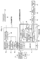
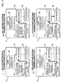
- Fig. 1 is a block diagram showing a construction of an ultrasonographic device of this embodiment.
- the ultrasonographic device includes a probe 1, a transmitter 3 and a receiver 5.
- the probe 1 transmits/receives an ultrasonic wave.
- the transmitter 3 outputs a drive signal for the probe 1.
- the receiver 5 is for a reflection echo signal (called reception signal, hereinafter) output from the probe 1.
- a transmit/receive separator 7 is provided therein for transmitting a drive signal output from the transmitter 3 and transmitting a reception signal output from the probe 1 to the receiver 5.
- a scan aperture switcher 9 is provided between the probe 1 and the transmit/receive separator 7.
- the scan aperture switcher 9 selects a transducer having the aperture of the probe 1 from multiple transducers of the probe 1.
- a signal processor 13, an image processor 15 and a display unit 17 are provided therein.
- the signal processor 13 performs detection processing, for example, on a reception signal output from the receiver 5.
- the image processor 15 reconstructs an ultrasonograph based on a signal processed by the signal processor 13.
- the display unit 17 displays the ultrasonograph reconstructed by the image processor 15.
- a controller 37 that outputs commands to these components is further provided therein.
- the transmitter 3 has a modulation waveform selector 19, a transmission pulse generator 21 and a power amplifier 23.
- the modulation waveform selector 19 selects a desired modulation encoding coefficient from prestored modulation encoding coefficients, and outputs the modulation encoding coefficient.
- the modulation encoding coefficient is included in a modulation code and has multiple code elements.
- the transmission pulse generator 21 modulates a transmission ultrasonic signal pulse (called basic wave, hereinafter) based on a modulation encoding coefficient output from the modulation waveform selector 19, and outputs the modulated basic wave as an encoding drive signal.
- the power amplifier 23 amplifies and outputs to the transmit/receive separator 7 the encoding drive signal output from the transmission pulse generator 21.
- a transmission controller 25 is further provided therein that outputs commands to the modulation waveform selector 19, transmission pulse generator 21 and power amplifier 23.
- the transmission controller 25 may include a bus controller, a register, a selector, a memory and a
- the receiver 5 has an amplifier 4 and a code demodulator 11.
- the amplifier 4 amplifies a reception signal input from the transmit/receive separator 7 based on a command output form the controller 37.
- the code demodulator 11 has a demodulation coefficient selector 27, a demodulator filter 29, a line memory 31 and synthesizer 33.
- the demodulation coefficient selector 27 selects and outputs a desired demodulation encoding coefficient from prestored demodulation encoding coefficients.
- the demodulation encoding coefficient is included in a demodulation code and includes multiple code elements corresponding to modulation encoding coefficients of a modulation code.
- the demodulation filter 29 demodulates a reception signal output from the amplifier 4 based on the demodulation coefficient output from the demodulation coefficient selector 27.
- the line memory 31 temporarily holds the reception signal output from the demodulation filter 29.
- the synthesizer 33 synthesizes the reception signal output form the demodulation filter 29 and the reception signal loaded from the line memory 31.
- a code demodulation controller 35 is further provided therein that outputs commands to the demodulation coefficient selector 27 and the line memory 31.
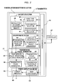
- Fig. 2 is a block diagram showing a detail construction of the transmitter 3.
- the modulation waveform selector 19 includes a code selector 39 and a waveform selector 41.
- the code selector 39 has a code type selector 43, a code length selector 45, a code interval selector 47 and a modulation encoding coefficient memory 49.
- the modulation encoding coefficient memory 49 holds modulation encoding coefficients obtained by calculations in advance.
- the code type selector 43 selects a type of modulation code (such as Golay code) in accordance with a command output from the transmission controller 25.
- the code length selector 45 selects a code length of a modulation code in accordance with a command output from the transmission controller 25.
- the code length refers to the number of code elements included in a modulation code.
- the code interval selector 47 selects an interval between modulation codes. The information (parameters) on the selected type, code length and interval are included in a modulation code.
- the modulation encoding coefficient memory 49 reads out and outputs to the transmission pulse generator 21 a proper modulation encoding coefficient from the modulation encoding coefficients based on the code type selected by the code type selector 43, the code length selected by the code length selector 45 and the code interval selected by the code interval selector 47.
- the code type selector 43, code length selector 45 and code interval selector 47 may include a register and a selector.
- the modulation encoding coefficient memory 49 may include a storage element such as an SRAM and a DRAM.
- the waveform selector 41 includes an envelope selector 51, a number-of-waves selector 53 and a transmission waveform selection memory 55.
- the transmission waveform selection memory 55 holds data on waveforms obtained by calculations in advance.
- the envelop selector 51 selects an envelope form in accordance with a command output form the transmission controller 25.
- the number-of-waves selector 53 selects the number of waves in accordance with a command output form the transmission controller 25.
- the transmission waveform selection memory 55 reads out proper data among data on waveforms based on the envelop form selected by the envelop selector 51 and the number of waves selected by the number-of-waves selector 53 and outputs the read data to the transmission pulse generator 21 as a basic wave.
- the envelope selector 51 and the number-of-waves selector 53 may include a register and a selector.
- the transmission waveform selection memory 55 may includes a storage element such as an SRAM and a DRAM.
- the transmission pulse generator 21 includes a transmission focus selector 57, a transmission focus delay generator 59, a transmission pulse waveform storage memory 61 and a transmission pulse generator 62.
- the transmission focus selector 57 defines the depth of transmission focus in accordance with a command output from the transmission controller 25.
- the depth of transmission focus refers to a depth that an ultrasonic transmission beam is converged within a subject.
- the transmission focus delay generator 59 outputs a transmission timing pulse to the transmission pulse waveform storage memory 61 based on the depth of transmission focus defined by the transmission focus selector 57.
- the transmission timing pulse refers to a signal that delays a transmission timing by a delay time defined for each transducer (channel) included in th aperture of th probe 1.
- the transmission waveform storage memory 61 selects a proper transmission pulse waveform from the transmission pulse waveforms obtained by calculations in advance based on a modulation encoding coefficient output from the modulation encoding coefficient memory 49 and a basic wave output from the transmission waveform selection memory 55.
- the transmission focus selector 57 may includes a register and a selector.
- the transmission focus delay generator 59 may includes a shift register, a selector, a counter and a frequency divider.
- the transmission pulse waveform storage memory 61 may include a storage element such as an SRAM and a DRAM.
- the transmission pulse generator 62 may include a digital-analog (D-A) converter and a buffer amplifier.
- the transmission waveform storage memory 61 outputs the selected transmission pulse waveform to the transmission pulse generator 62 in synchronization with a sampling clock when the transmission timing pulse output from the transmission focus delay generator 59 is enabled.
- the transmission pulse generator 62 converts a transmission pulse waveform of a digital signal output from the transmission pulse waveform storage memory 61 to an analog voltage value or current value by the digital-analog converter and outputs the converted transmission pulse waveform to the power amplifier 23 as an encoding drive signal.
- the power amplifier 23 includes a gain controller 63 and a power amplifier 26.
- the gain controller 63 outputs a proper gain value to the power amplifier 65 in accordance with a command output from the transmission controller 25.
- the power amplifier 65 amplifies and outputs to the transmission/reception separator 7 a gain of the encoding drive signal output from the transmission pulse generator 62 in accordance with the gain value output from the gain controller 63.
- the gain controller 63 may include a register and a selector.
- the power amplifier 65 may include an amplification FET and an adjustable gain amplifier.
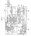
- Fig. 3 is a block diagram showing a detail construction of the code demodulator 11.
- the demodulation coefficient selector 27 of the code demodulator 11 has a demodulation code type selector 67, a demodulation code length selector 69, a demodulation code interval selector 71 and a demodulation encoding coefficient memory 73.
- a code demodulation controller 35 is provided therein that outputs commands to the demodulation code type selector 67, demodulation code length selector 69 and demodulation code interval selector 71.
- the demodulation code type selector 67 selects a type of demodulation code in accordance with a command output from the code demodulation controller 35.
- the demodulation code length selector 69 selects a code length of a demodulation code in accordance with a command output from the demodulation code controller 35.
- the demodulation code interval selector 71 selects a code interval between demodulation codes in accordance with a control command output from the code demodulation controller 35.
- the demodulation encoding coefficient memory 73 holds demodulation encoding coefficients calculated by calculations in advance.
- the demodulation encoding coefficient memory 73 reads out and outputs to the demodulation filter 29 a proper demodulation encoding coefficient from the demodulation encoding coefficients in accordance with the type of demodulation code selected by the demodulation code type selector 67, the code length selected by the code length selector 69 and the code interval selected by the demodulation code interval selector 71.
- the parameters including the code type selected by the code type selector 43, the code length selected by the code length selector 45 and the code interval selected by the code interval selector 47 correspond to the parameters for the modulation code selected by the code selector 39 of the modulation waveform selector 19.
- the demodulation code type selector 67, demodulation code length selector 69 and demodulation code interval selector 71 may include a register and a selector.
- the demodulation encoding coefficient memory 73 may have a storage element such as an SRAM and a DRAM.
- the demodulation filter 29 has a reception signal delaying unit 75 and a product adder 77.
- the reception signal delaying unit 75 performs phasing processing for a so-called reception focus on each reception signal output from the amplifier 4.
- the reception signal to be phased corresponds to the signal received by each vibrate included in the aperture of the probe 1.
- the product adder 77 adds the reception signals phased by the reception signal delaying unit 75.
- the product adder 77 further code-demodulates and outputs to th line memory 31 the added reception signal based on the demodulation encoding coefficient output from the demodulation encoding coefficient memory 73.
- the reception signal delaying unit 75 may include a shift register, a selector a counter and a frequency divider.
- the product adder 77 may include a multiplier, adder, a selector and an FIR filter.
- the line memory 31 has a line memory controller 79 and a memory 81.
- the line memory controller 79 outputs a command to the memory 81 based on a command output from the code demodulation controller 35.
- the memory 81 temporarily holds the reception signal demodulated by the product adder 77.
- the memory 81 further outputs a held reception signal to the synthesizer 33 in accordance with a command output from the line memory controller 79.
- the line memory controller 79 may includes a register, a frequency divider, a comparator, a counter and a selector.
- the memory 81 may include a storage element such as an SRAM and a DRAM.
- the synthesizer 33 has a synthesis coefficient selector 83 and a signal synthesizer 85.
- the synthesis coefficient selector 83 selects a synthesis coefficient in accordance with a command output from the code demodulation controller 35.
- the signal synthesizer 85 synthesizes a predetermined number of reception signals output with delays in time from the memory 81 based on the synthesis coefficient selected by the synthesis coefficient selector 83 and outputs the synthesized reception signal to the signal processor 13.
- the synthesis coefficient selector 83 may include a register and a selector.
- the signal synthesizer 85 may include a multiplier, an adder and a positive-negative inversion computing unit.
- an ultrasonograph is acqured by the ultrasonographic device.
- an encoding drive signal for the probe 1 is generated by the transmitter 3.
- the generated encoding drive signal is input to the probe 1 through the transmission/reception separator 7 and the scan aperture switcher 9.
- the encoded ultrasonically-encoded beam is emitted from the probe 1 to a subject.
- the ultrasonic wave reflected by the subject is received by the probe 1.
- the received ultrasonic wave undergoes amplification processing by the receiver 5 as a reception signal and then is code-demodulated.
- the demodulated reception signal is detected by the signal processor 13 and is reconstructed to an ultrasonograph (such as a B-mode image and an M-mode image) by the image processor 15.
- the reconstructed ultrasonograph is displayed on the display screen of the display unit 17.
- a type of code (such as Golay code) is first selected by the code type selector 43 in accordance with a command output from the transmission controller 25, for example.
- a code length (such as a code length of 4) is selected by the code length selector 45.
- a code interval (such as a wavelength X) is selected by the code interval selector 47.
- the wavelength ⁇ refers to a wavelength corresponding to the center frequency of an ultrasonic transmission signal.
- a proper modulation encoding coefficient is loaded from the encoding coefficient memory 49 based on the code type selected by the code type selector 43, the code length selected by the code length selector 45 and the code interval selected by the code interval selector 47.
- the processing is repeated at defined time intervals in accordance with commands from the transmission controller 25.
- a basic wave of a drive signal is generated by the waveform selector 41.
- an envelope of a transmission waveform is first selected by the envelope selector 51.
- the number of waves of the transmission waveform is selected by the number-of-waves selector 53.
- Desired transmission waveform data are selected by the transmission waveform selection memory 55 based on the selected envelope and number of waves.
- the selected transmission waveform data are output to the transmission pulse waveform storage memory 61 as the basic wave of the drive signal.
- the depth of transmission focus is defined by the transmission focus selector 57.
- a delay time is defined by the transmission focus delay generator 59 based on the defined depth of transmission focus.
- the transmission timing pulse based on the defined delay time is output from the transmission focus delay generator 59 to the transmission pulse waveform storage memory 61.
- a transmission pulse waveform is selected as an encoding drive signal by the transmission pulse waveform storage memory 61 based on the modulation encoding coefficient output form the modulation encoding coefficient memory 49 and the basic wave output from the transmission waveform selection memory 55.
- the selected encoding drive signal is a waveform resulting from the code-modulation of the basic wave with the modulation encoding coefficient.
- the encoding drive signal is loaded from the transmission pulse waveform storage memory 61 when the transmission timing pulse output from the transmission focus delay generator 59 is enabled (ON).
- the loaded encoding drive signal is output to the transmission pulse generator 62.
- the output encoding drive signal is converted from a digital signal to an analog signal by the transmission pulse generator 62.
- the converted encoding drive signal is output to the power amplifier 23.
- a desired gain value is defined by the gain controller 63 in accordance with a command output from the transmission controller 25.
- the gain of the encoding drive signal output from the transmission pulse generator 62 is amplified by the power amplifier 65 based on the defined gain value.
- the amplified encoding drive signal is input to the scan aperture switcher 9 through the transmission/reception separator 7.
- the input encoding drive signal is assigned to each transducer in the aperture of the probe 1 by the scan aperture switcher 9.
- the assigned encoding drive signal is input to each transducer in the aperture of the probe 1.
- the input encoding drive signal is converted by each transducer to an ultrasonic wave of a mechanical signal.
- the converted ultrasonic wave is transmitted as an ultrasonic transmission beam from the probe 1 to a subject.
- the ultrasonic transmission beam is formed by advancing in a direction that the wavefronts of the transmitted ultrasonic waves agree, that is, in a direction of depth of a subject.
- modulation codes A, B, -B and -A are selected as one set in the processing of generating an encoding drive signal.
- the encoding drive signal is generated by each of the selected modulation codes.
- encoding transmission is repeated four times at defined time intervals by the generated four encoding drive signals.
- the first modulation code A and the second modulation code B are first selected as a pair of Golay codes at defined time intervals by the code selector 39.
- Each of the selected modulation codes A and B is a modulation encoding coefficient including four code elements.
- the modulation encoding coefficient of the modulation code A is (1,1,1,-1).
- the modulation encoding coefficient of the modulation code B is (-1,1,-1,-1).
- the modulation encoding coefficient of the modulation code A and the modulation encoding coefficient of the modulation code B and defined to be orthogonal to each other.
- the modulation code A and modulation code B are in complementary relationship.
- the set having the modulation codes A and B in order is called encoding set.
- the multiple code elements of each of the modulation codes A and B are combined to diffuse energy of a basic wave toward the time axis and generate an encoding drive signal.
- the third modulation code -B and the fourth modulation code -A are selected at defined time intervals by the code type selector 43, code length selector 45 and code interval selector 47.
- the third modulation code -B is a code having the inverted polarity of the polarity of the second modulation code B.
- the fourth modulation code -A is a code having the inverted polarity of the polarity of the first modulation code A.
- the inversion of a polarity here refers to the rotation of a phase by 180 degrees. Therefore, the modulation encoding coefficient of the modulation code - B is (1,-1,1,1).
- the modulation encoding coefficient of the modulation code -A is (-1,-1,-1,1).
- the set having the modulation codes -B and -A in order is called inverted encoding set.
- the first to fourth modulation codes are collectively called one code packet.
- encoding transmission/reception is repeated four times on one scan line at defined time intervals based on the first to fourth modulation codes A, B, -B and -A included in one code packet.
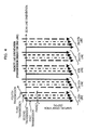
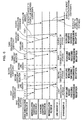
- Fig. 4 shows a method of the encoding transmission/reception repeated four times on one scan line.
- an ultrasonic transmission beam scans inside of a subject by shifting the direction to transmit (scan line) toward the aperture and is repeatedly transmitted. Then, in this embodiment, four encoding transmissions/receptions are performed on each scan line. For example, a first ultrasonic transmission beam based on the modulation code A is transmitted to a first scan line, and a reception signal corresponding to the ultrasonic transmission beam is received therefrom. Next, a second ultrasonic transmission beam based on the modulation code B is transmitted thereto, and a reception signal corresponding to the ultrasonic transmission beam is received therefrom.
- a third ultrasonic transmission beam based on the modulation code -B is transmitted thereto, and a reception signal corresponding to the ultrasonic transmission beam is received therefrom.
- a fourth ultrasonic transmission beam based on the modulation code -A is transmitted thereto, and a reception signal corresponding to the ultrasonic transmission beam is received therefrom.
- the four encoding transmissions/receptions are performed on each of scan lines (1, 2, ..., N-2, N-1, N, N+1, N+2, .
- the ultrasonic transmission beam is emitted from the probe 1 by an encoding drive signal, and the emitted ultrasonic transmission beam propagates inside of a subject. Then, the ultrasonic transmission beam is reflected as a reflection echo signal by a part where an acoustic impedance varies, such as the surface of an organ. A part of the reflection echo signal is received by multiple transducers in the aperture in the probe 1. The received reflection echo signal is converted to an electric signal, and the converted electric signal is output as a reception signal from the probe 1.
- the reception signal output from the probe 1 is output to the scan aperture switcher 9.
- the output reception signal is output to the receiver 5 through the transmission/reception separator 7.
- each reception signal input to the receiver 5 undergoes processing such as amplification by the amplifier 4.
- Each, for example, amplified reception signal is phased by reception focus processing by the reception signal delaying unit 75.
- the reception focus processing refers to processing of phasing a reception signal between channels in consideration of differences in propagation time of reception signals from a reflection source of the reception signals to the transducers and by delaying the reception signal of each of the channels by each different amount of delay.
- the type of demodulation code is selected by the demodulation code type selector 67 in accordance with a command from the code demodulation controller 35. Furthermore, the code length of the demodulation code is selected by the demodulation code length selector 69. Furthermore, the code interval between demodulation codes is selected by the demodulation code interval selector 71. Next, a proper demodulation encoding coefficient is loaded from the demodulation encoding coefficient memory 73 based on the code type selected by the demodulation code type selector 67, the code length selected by the demodulation code length selector 69 and the code interval selected by the demodulation code interval selector 71. The loaded demodulation encoding coefficient is output to the product adder 77.
- the output demodulation encoding coefficient is a modulation encoding coefficient selected by the modulation waveform selector 19 (such as (-1,1,1,1) corresponding to the modulation encoding coefficient (1,1,1,-1) of the modulation code A).
- the demodulation encoding coefficient is a demodulation code and includes multiple code elements. The multiple code elements of the demodulation encoding coefficient are combined to converge energy of a reception signal and demodulate the reception signal.
- reception signals phased by the reception signal delaying unit 75 are added by the product adder 77.
- the reception signal is obtained as an ultrasonic reception beam.
- the reception signal is multiplied by the demodulation encoding coefficient output from the demodulation encoding coefficient memory 73 by the product adder 77.
- the reception signal is code-demodulated.
- the demodulated reception signal is held by the memory 81.
- the four encoding transmissions/receptions are repeated on one scan line with one code packet.
- four reception signals are obtained by each encoding transmission/reception.
- the four reception signals are sequentially held in the memory 81.
- the held first to fourth reception signals are, as shown in Fig. 5, synthesized in code packets by the synthesizer 33 for each scan line. In other words, the first to fourth reception signals are synthesized within one code packet.
- FIG. 5 is a diagram for explaining with reference to block diagrams.
- Fig. 6 is a diagram for explaining with reference to a time chart.
- Fig. 5, (i) to (iv), and Fig. 6, (i) to (iv), show operations for demodulating and synthesizing reception signals corresponding to first to fourth ultrasonic transmission beam to the N th scan line.
- the reception signal corresponding to the first modulation code A is code-demodulated by the demodulation filter 29.
- the demodulated reception signal is held in the line memory 31.
- the reception signal corresponding to the second modulation code B is held in the line memory 31 through the demodulation filter 29.
- the reception signal corresponding to the third modulation code -B and the reception signal corresponding to the fourth modulation code -A are also held in the line memory 31 in order. Then, as shown in Fig.
- reception signals are adjusted to have the same time axis by the signal synthesizer 85.
- the reception signals are adjusted to a sampling point corresponding to the direction of depth within a subject.
- the reception signals having the same time axis are synthesized by the signal synthesizer 85 based on a synthesis coefficient output from the synthesis coefficient selector 83.
- the synthesized reception signal is output to the downstream signal processor 13.
- the encoding reception signal, code-demodulated reception signal (demodulation signal), reception signal resulting from synthesis of the demodulation signal (demodulation synthesis signal) and final synthesis signal resulting from further synthesis of the demodulation synthesis signal (synthesis signal) will be described by comparing with an existing encoding transmission/reception technology with reference to simulation results (examples).
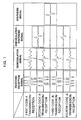
- Fig. 7 shows simulation results and the fact that the time side lobe is reduced even when an amplification distortion occurs in a reception signal due to a body motion of a subject, for example.
- Fig. 7 shows graphs having waveforms of an encoding reception signal, demodulation signal, first and second synthesis signals and third synthesis signal in order from the left column.
- the first and second synthesis signals are referred by the first and second demodulation synthesis signals, and the third synthesis signal is referred by the synthesis signal.
- the vertical axis of the graphs indicates strength of signals.
- the horizontal axis of the graphs indicates time.
- FIG. 7 shows a case of the first encoding transmission/reception based on the modulation code A, a case of the second encoding transmission/reception based on the modulation code B, a case of the third encoding transmission/reception based on the modulation code -B and a case of the fourth encoding transmission/reception based on the modulation code -A in order from the top column.
- the first to fourth encoding reception signals are signals resulting from reflection of ultrasonic transmission beams based on the modulation codes A, B, -B and -A.
- the encoding reception signals have the third and fourth amplitudes reduced by an amplitude distortion caused due to a body motion, for example.
- the demodulation signal also has a reduced amplitude.
- both first demodulation synthesis signal P1 and second demodulation synthesis signal P2 have an equivalent waveform where the first and second demodulation signals are synthesized to obtain the first demodulation synthesis signal P1, and the third and fourth demodulation signals are synthesized to obtain the second demodulation synthesis signal P2.
- all of the demodulation synthesis signals should be reconstructed with one cycle of pulse waves having a wavelength ⁇ .
- each of the demodulation synthesis signals P1 and P2 has a time side lobe before and after a main lobe in the direction of time.
- the time side lobes occurring in the demodulation synthesis signals P1 and P2 have an equal amplitude and inverted polarities.
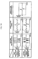
- Fig. 8 shows similar graphs to those in Fig. 7 but shows a case that a phase distortion due to a body motion occurs in an encoding reception signal instead of an amplitude distortion.
- the time side lobe due to a body motion occurs in each of the demodulation synthesis signals P1 and P2.
- further synthesizing the demodulation synthesis signal P1 and demodulation synthesis signal P2 results in a synthesis signal having a reduced time side lobe.
- a case that a frequency distortion occurs in an encoding reception signal may be handled in the same manner as that of the case that an amplitude distortion occurs in an encoding reception signal (Fig. 8).
- Fig. 9 is a graph for explaining encoding transmission/reception using a pair of Golay codes according to a conventional technology.
- the encoding drive signal is generated by modulating a drive signal (basic wave) with the modulation code A (1,1,1,-1) and modulation code B (-1,1,-1,-1) selected as the Golay codes.
- Each of the modulation codes A and B is a code having a code length of 4 including four code elements.
- the modulation code A and modulation code B are in complementary relationship.
- the code interval between the modulation codes A and B is 1 ⁇ .
- the modulation codes A and B have orthogonality and cancel the time side lobes due to code demodulations with each other.
- the first encoding reception signal is a signal resulting from reflection of an ultrasonic transmission beam based on the modulation code A.
- the second encoding reception signal is a signal resulting from reception of an ultrasonic transmission beam based on the modulation code B.
- a time side lobe due to a code demodulation occurs in the demodulation signal resulting from demodulation of the first encoding reception signal. The same is true in the second demodulation signal.
- the time side lobes occurring in the first and second demodulation signals have an equal amplitude and inverted polarities of each other.
- synthesizing the first demodulation signal and second demodulation signal results in a demodulation synthesis signal in which the time side lobes due to the code demodulation are canceled with each other.
- the time side lobes due to a code demodulation can be reduced by performing encoding transmission/reception with Golay codes of the conventional technology.
- a subject may move or a form of a subject may vary during a time interval between the first ultrasonic transmission beam and second ultrasonic transmission beam.
- a time side lobe occurs due to a body motion (such as movement) of a biological tissue.
- a time side lobe due to a body motion occurs with complementary codes typically such as Golay codes.
- the signal strength of the time main lobe of the demodulation synthesis signal is a strength resulting from multiplication of the signal strength of a reception signal in a case that no encoding transmission/reception is performed by the code length and number of encoding transmissions/receptions.
- the code length is "4"
- Fig. 10 is a similar graph to that in Fig. 9 but shows an example in which a time side lobe due to a body motion of a biological tissue occurs in a demodulation synthesis signal because a subject moves during a time interval between the first ultrasonic transmission beam and the second ultrasonic beam.
- the time main lobes of the first and second demodulation signals have different signal strengths but have the same polarity. Therefore, as shown in the right column in Fig. 10, the time main lobe of the demodulation synthesis signal have an emphasized signal strength.
- the middle column in Fig. 10 shows an example in which a time side lobe due to a body motion of a biological tissue occurs in a demodulation synthesis signal because a subject moves during a time interval between the first ultrasonic transmission beam and the second ultrasonic beam.
- the time side lobes of the first and second demodulation signals have inverted polarities of each other and have an amplitude shift from each other. Therefore, as shown in the right column in Fig. 10, synthesizing the first and second demodulation signals results in a demodulation synthesis signal in which the time side lobes are not cancelled with each other but the time side lobes remain.
- Fig. 11 is a similar graph to that in Fig. 10 but shows a state that a phase distortion occurs in an encoding reception signal due to a body motion of a subject. Like the case in Fig. 10, the time side lobe of the demodulation synthesis signal remains without being cancelled.
- the time side lobe due to nonlinearity of a medium of a subject can be reduced, and the time side lobe due to a body motion of a subject can be reduced. Therefore, the resolution of an ultrasonograph can be further enhanced.
- Synthesizing the obtained demodulation signals results in a demodulation synthesis signal P2 (second synthesis signal).
- the time side lobe occurring in the demodulation synthesis signal P2 is an equivalent signal to the one due to the body motion resulting from relatively reverse movement of a subject with reference to that of the time side lobe of the demodulation synthesis signal P1.
- Synthesizing the demodulation synthesis signal P1 and demodulation synthesis signal P2 results a synthesis signal (third synthesis signal) which is a signal in which the time side lobes occurring in the demodulation synthesis signal P1 and demodulation synthesis signal P2 due to an amount of movement of a subject are cancelled with each other.
- the synthesis signal can be equivalent to a signal obtained when the subject is substantially still.
- the demodulation synthesis signal P1 and demodulation synthesis signal P2 are synthesized, the time side lobe of the demodulation synthesis signal P1 and the time side lobe of the demodulation synthesis signal P2 cancel with each other, which can reduce the time side lobe due to a body motion of a subject.
- the demodulation synthesis signal P1 may be called forward reception signal
- the demodulation synthesis signal P2 may be called reverse reception signal.
- time side lobes occurring in demodulation synthesis signals can be cancelled with each other when a subject performs an ideal movement at a uniform speed, and the time side lobe due to the body motion can be reduced even when a subject performs a complicated movement since the movement can be regarded as a movement at a substantially uniform speed within a shorter period of time.
- a pair of Golay codes is used as an encoding set including two modulation codes
- various kinds of codes may be selected and used such as Orthogonal Complemental Pair codes (IEEE Trans, on Information Theory, vol. IT-24, No. 5 Sept. 1978, P. 546-552).
- an encoding set including three modulation codes may be used.
- the reverse encoding set may include a fourth modulation code -Z having the inverted polarity of that of the third modulation code Z, a fifth modulation code -Y having the inverted polarity of that of the second modulation code Y, and a sixth modulation code -X having the inverted polarity of that of the first modulation code.
- the modulation code -X is a code resulting from the rotation of the phase of the modulation encoding coefficient of the modulation code X by a predetermined number of phases. The same is true for the modulation codes -Y and -Z. Thus, the time side lobe can be more reduced.
- each of the modulation codes of the reverse encoding set can be defined in the same manner as that for the case having three modulation codes.
- the Mth modulation code in the reverse encoding set may have the inverted polarity of that of the (N-M+1)th modulation code in the encoding set, where N is a natural number equal to or higher than 5, and M is a natural number equal to or lower than N.
- the multiple modulation codes in the reverse encoding set may have phases resulting from rotation of the phases of the modulation codes in the encoding set.
- the time side lobe due to a body motion of a subject can be reduced, and, at the same time, the time side lobe due to nonlinearity of a medium within a subject can also be reduced.
- the code interval between modulation codes is 1 ⁇ was described, but the code interval may be 1.5 ⁇ or 2 ⁇ instead.
- the modulation encoding coefficient of the modulation code A may be (1,0,1,0,1,0,-1)
- the modulation encoding coefficient of the modulation code B may be (-1,0,1,0,-1,0,-1).
- modulation encoding coefficients are obtained by calculations in advance and the modulation encoding coefficients are stored in the modulation encoding coefficient memory 49
- a modulation encoding coefficient may be calculated and obtained by a CPU, for example, based on information on the type of modulation code, code length and code interval instead.
- a transmission waveform may be calculated and obtained by a CPU for transmission waveform pulse waveforms based on the modulation encoding coefficient.
- a second embodiment applying the present invention will be described.
- This embodiment is different from the first embodiment in that reception signals obtained from multiple scan lines having different directions are synthesized between scan lines. Therefore, the description of identical parts to those of the first embodiment will be omitted herein, and only differences will be described. Identical reference numerals are given to the identical parts in the description.
- Fig. 12 is a block diagram showing a construction and operation of a code demodulator of this embodiment.
- Fig. 13 is a time chart showing an operation of the code demodulator in Fig. 12.
- the code demodulator of this embodiment preferably configured to synthesize reception signals between scan lines.
- the code modulator 11 has a packet line memory 91 and a packet line synthesizer 93 instead of the line memory 31 and synthesizer 33 in the first embodiment.
- An output signal of the demodulation filter 29 is input to the packet line memory 91.
- An output signal of the demodulation filter 29 or packet line memory 91 is input to the packet line synthesizer 93.
- the code demodulator 11 further includes a scan line memory 95 and a scan line synthesizer 97.
- An output signal of the packet line synthesizer 93 is input to the scan line memory 95.
- An output signal of the packet line synthesizer 93 or scan line memory 95 is input to the scan line synthesizer 97.
- the packet line memory 91 and scan line memory 95 are controlled by a code demodulation controller 35.
- encoding transmissions/receptions are performed by using an encoding set including two modulation codes A and B and a reverse encoding set including two modulation codes -B and -A.
- the first to third encoding transmissions/receptions are performed on the Nth scan line.
- the first to third reception signals are demodulated by the demodulation filter 29.
- the demodulated first to third reception signals are sequentially held by the packet line memory 91.
- the fourth encoding transmission/reception is performed on the Nth scan line.
- the fourth reception signal is demodulated by the demodulation filter 29.
- the demodulated fourth reception signal is output to the packet line synthesizer 93.
- the first to third reception signals are also loaded from the packet line memory 91 and output to the packet line synthesizer 93.
- a synthesis coefficient selected by the synthesis coefficient selector 83 is output to the packet line synthesizer 93 in accordance with a command output from the code demodulation controller 35.
- the first to fourth reception signals are synthesized by the packet line synthesizer 93 based on the output synthesis coefficient.
- the synthesized reception signal is output to both of the scan line memory 95 and scan line synthesizer 97.
- the scan line memory 95 holds a last reception signal.
- the last reception signal is a reception signal from the (N-1)th scan line, for example.
- the reception signal in the Nth scan line is input from the packet line synthesizer 93 to the scan line synthesizer 97
- the reception signal in the (N-1)th scan line is loaded from the scan line memory 95.
- a synthesis coefficient selected by the synthesis coefficient selector 83 is output to the scan line synthesizer 97 in accordance with a command output from the code demodulation controller 35.
- the reception signals in the (N-1)th scan line and Nth scan line are synthesized by the scan line synthesizer 97 based on the output synthesis coefficient.
- a diagnosis image for the pixel position corresponding to the Nth scan line is created by the signal processor 13 and image processor 15 based on the synthesized reception signal.
- the reception signals in the (N-1)th and Nth scan lines are to be synthesized between scan lines by the scan line synthesizer 97, the reception signals may be synthesized easily at a ratio of 1:1 where the synthesis coefficient to be supplied to the scan line synthesizer 97 is (1,1).
- the reception signal in a first scan line (such as the (N-1)th scan line) and the reception signal in a second scan line (such as the Nth scan line adjacent to the (N-1)th scan line) different from the first scan line are synthesized based on a synthesis coefficient.
- the time side lobe due to a body motion can be more reduced.
- the memory 81 of the first embodiment is divided into the packet line memory 91 and scan line memory 95 in this embodiment. Therefore, the line memory can be efficiently used.
- This example is an example in which reception signals in two scan lines having different directions are synthesized across scan lines. More specifically, the encoding transmission/reception on the (N-1)th scan line is performed by using an encoding set including two modulation codes A and B and a reverse encoding set including two modulation codes -B and -A. Next, the encoding transmission/reception on the Nth scan line adjacent to the (N-1)th scan line is performed by using the encoding set and reverse encoding set in the reverse order. In other words, the encoding transmission/reception on the Nth scan line and the (N-1)th encoding transmission/reception are performed in the reverse order.
- the encoding transmission/reception on the (N-1)th scan line are performed based on the modulation codes A, B, -B and -A.
- the encoding transmission/reception on the Nth scan line are performed based on the modulation codes -B, -A, A and B.
- reception signals in the (N-1)th scan line are synthesized between the code packets by the packet synthesizer 93.
- the reception signals in the Nth scan line are synthesized between the code packets. Further synthesizing synthesis signals based on a synthesis coefficient results in a signal synthesis signals across the (N-1)th and Nth scan lines (inter-scan-line synthesis signal). An ultrasonograph on the Nth scan line can be reconstructed based on the resulting inter-scan-line synthesis signal.
- the time side lobe occurring in the synthesis signal at the (N-1)th scan line is a signal due to a body motion that a subject moves forwardly.
- the time side lobe occurring in the synthesis signal at the Nth scan line is equivalent to the time side lobe due to a body motion that the subject moves relatively in the reverse direction.
- encoding transmissions/receptions may be performed on two different scan lines in opposite orders of implementation of encoding transmissions/receptions against each other.
- This example is an example in which four ultrasonic transmission beams based on one code packet are divided and transmitted to multiple scan lines.
- the encoding transmission/reception on the (N-1)th scan line is performed by using modulation codes A and B.
- the encoding transmission/reception on the Nth scan line is performed by using modulation codes -B and -A.
- the reception signals in the (N-1)th and Nth scan lines are synthesized for each scan line by the packet line synthesizer 93 based on a synthesis coefficient.
- the reception signals resulting from the synthesis for each scan line are further synthesized across scan lines by the scan line synthesizer 97.
- a diagnosis image corresponding to the Nth scan line is reconstructed based on the synthesis signal. In this way, an encoding transmission/reception for synthesizing code packets across multiple (such as two) scan lines is repeated on each scan line.
- the number of transmissions/receptions on each scan line can be reduced. Therefore, the time side lobe due to a body motion can be reduced, and the frame rate of an ultrasonograph can be enhanced.
- This example is an example in which encoding transmissions/receptions are performed on a set of four scan lines.
- the encoding transmission/reception on the (N-2)th scan line is performed by using a modulation code A.
- the encoding transmission/reception on the (N-1)th scan line is performed by using a modulation code B.
- the encoding transmission/reception on the Nth scan line is performed by using a modulation code -B.
- the encoding transmission/reception on the (N+1)th scan line is performed by using a modulation code -A.
- the reception signals of the scan lines are synthesized by the scan line synthesizer 97.
- the diagnosis image corresponding to the (N+1)th scan line is reconstructed.
- ultrasonic beams corresponding to modulation codes in an encoding set may be divided and transmitted to multiple first scan lines
- ultrasonic beams corresponding to modulation codes in the reverse encoding set may be divided and transmitted to multiple second scan lines at least partially different from the multiple first scan lines.
- This example is an example in which scan lines are interpolated with a virtual scan line when multiple ultrasonic beams based on one code packet are divided and transmitted to multiple scan lines.
- the reception signals resulting from the synthesis on each of the (N-1)th and Nth scan lines are further synthesized by the scan line memory 95, the code demodulation controller 35 changes a synthesis coefficient to be supplied to the scan line memory 95.
- the number of virtual scan lines increases. Therefore, the resolution of the ultrasonograph can be enhanced. More specifically, when a synthesis is performed between the (N-1)th and Nth scan lines, the synthesis coefficients are (1/4,3/4), (2/4,2/4) and (3/4,1/4). Thus, three interpolating lines are defined between the (N-1)th and Nth scan lines (adjacent scan lines). Therefore, since the number of virtual lines increases, the resolution of the ultrasonograph can be enhanced.
- Fig. 14 is a block diagram showing a construction and operation of a code demodulator of this embodiment.
- Fig. 15 is a time chart showing an operation of the code demodulator in Fig. 14.
- This embodiment is similar to the code demodulator of the second embodiment except for the operating method of processing of synthesizing reception signals. Therefore, the description of the identical parts in the third embodiment will be omitted herein, and differences will be described. The identical reference numerals are given to identical parts therebetween in the description.
- the reception signal output from the demodulation filter 29 is directly input to the packet line synthesizer 93.
- a first reception signal by the last encoding transmission/reception held in the packet line memory 91 is loaded from the packet line synthesizer 93.
- the loaded first reception signal is synthesized to a second reception signal by the packet line synthesizer 93.
- the synthesized reception signal is returned to the packet line memory 91.
- a third reception signal output from the demodulation filter 29 is also further synthesized with a synthesized reception signal loaded from the packet line memory 91 by the packet line synthesizer 93.
- the synthesized reception signal is returned to the packet line memory 91.
- a fourth reception signal output from the demodulation filter 29 is further synthesized with a synthesized reception signal loaded from the packet line memory 91 and is output to the signal processor 13.
- a fourth embodiment applying the present invention will be described with reference to Figs. 16 and 17.
- This embodiment is different from the second embodiment in that the number of scan lines to which ultrasonic transmission beams based on one code packet are divided is determined by performing prescan for analyzing a correlation between reception signals with a scan ultrasonic transmission beam before encoding transmission/reception.
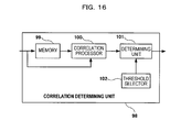
- Fig. 16 is a block diagram showing a construction of a correlation determining unit of this embodiment.
- a correlation determining unit 98 includes a memory 99, a correlation processor 100, a determining unit 101 and a threshold selector 102.
- the memory 99 includes a storage element such as an SRAM.
- the correlation processor 100 includes a computer that implements subtraction and addition calculations such as a DSP (Digital Signal Processor) and a CPU.
- the determining unit 101 includes a determining unit that compares input values.
- the threshold selector 102 includes a selector.
- Fig. 17 shows an example in which a spatial correlation is obtained by using prescanning, a specific sequence of the correlation determining unit 98 and a determining method.
- a range of interest ROI
- a predetermined number of scan lines 105 (such as scan lines in the first to sixth directions) to transmit scan ultrasonic transmission beams are defined for the target 103.
- each ultrasonic wave occurring in each scan line is received by the probe 1.
- Each of the received ultrasonic waves undergoes amplification processing by the amplifier 4 and then is output to the correlation determining unit 98 as multiple reception signals.
- Each of the reception signals input to th correlation determining unit 98 is stored in the memory 99.
- Correlation coefficients among the reception signals are obtained by the correlation processor 100 based on the reception signals loaded from the memory 99. For example, a correlation coefficient between reception signals in the first and second directions are obtained as zero (0) here.
- correlation coefficients in the second and third directions, the third and fourth directions, the fourth and fifth directions and the fifth and sixth directions are obtained as 0.4, 0.6, 0.3 and 0 here.
- Each of the obtained correlation coefficients is compared with a threshold value (such as 0.4) output from the threshold selector 102 by the determining unit 101.
- the correlation coefficient is determined as a valid value by the determining unit 101. Therefore, in this embodiment, those in the three directions of the second to fifth directions are determined as valid scan lines.
- the threshold value can be freely changed by an operator.
- Each of line addresses of the scan lines in the determined three directions is output from the correlation determining unit 98 to the controller 37. Then, based on the output line address, like the second embodiment, the ultrasonic transmission beams based on an encoding drive signal of one packet are divided and transmitted to the scan lines in the second to fifth directions.
- a spatial correlation of a subject (such as the size of the target 103) is detected before an encoding transmission/reception is performed. Therefore, if it is determined that the spatial change is small, the number of scan lines to be synthesized across multiple scan lines can be increased. As a result, the signal sensitivity may be enhanced and/or the time side lobe may be reduced.
- the number of scan lines synthesized across multiple scan lines can be reduced. Therefore, the occurrence of a halo and/or blurring in the ultrasonograph can be prevented since transmitted ultrasonic waves can be securely irradiated to the target 103.
- the maximum acceptable number of scan lines to be synthesized across multiple scan lines can be determined based on a spatial correlation. Therefore, dividing ultrasonic transmission beams to the maximum scan lines or fewer lines can prevent a halo and/or blurring in the ultrasonograph and achieve a desired signal sensitivity.
- the parameters such as a spatial resolution, sensitivity level and frame rate of an ultrasonograph may be input and defined by an operator through an input unit.
- the input unit may include a mouse and a keyboard.
- the display unit 17 displays a GUI (Graphical User Interface) for defining a parameter.
- prescanning may be performed when a part to be diagnosed is changed or may be performed periodically.
- prescanning may be started manually through a button or prescanning may be started automatically by automatically recognizing the fact that the part is moved from the target 103 based on a change in time, for example, of intensity data of a displayed image.
- a setting for validating or invalidating a prescanning function may be input from an input unit.
- the timing for performing prescanning may be a timing before multiple ultrasonic transmission beams are divided and transmitted from the probe 1 to multiple scan lines in accordance with an encoding drive signal corresponding to an encoding set and the reverse encoding set, a timing when parts to irradiate ultrasonic transmission beams transmitted from the probe 1 are changed or a predetermined timing.
- a correlation coefficient may be obtained based on: where N is a number of sampling points, and S1 and S2 are vector notations of S1 and S2.
- the number of samplings is "4" in this embodiment.
- the points n to n+3 are positions corresponding to the sample points corresponding to the target 103 in all sample points.
- Pearson product-moment correlation coefficient, Spearman's rank correlation coefficient or Kendall's rank correlation coefficient may be used. In other words, the large-and-small relationships of amounts of distribution of the values may be compared with the average.
- FIG. 18 shows an example in which a time correlation is obtained by using prescanning, a specific sequence of the correlation determining unit 98 and a determining method.
- This embodiment is different from the fourth embodiment in that the number of ultrasonic transmission beams to be transmitted to one scan line is determined by performing prescanning on one scan line before an encoding transmission/reception is performed.
- the description of identical parts to those of the fourth embodiment is omitted herein, and differences will be omitted herein.
- a correlation coefficients between reception signals is obtained by the correlation processor 100 of the correlation determining unit 98 based on the reception signals received by the probe 1. For example, when the target 103 moves by a body motion, correlation coefficients between reception signals at first and second times, second and third times, third and fourth times, fourth and fifth times and fifth and six times are obtained as 0, 0.6, 0.7, 0.4 and 0 here.
- the obtained correlation coefficients are compared by the determining unit 101 with a threshold value (such as 0.4) output from the threshold selector 102.
- a correlation coefficient equal to or higher than the threshold value is determined as a valid value by the determining unit 101. Based on the determined valid value, the number of transmissions/receptions to be performed on one scan line and the transmission timings are determined. For example, in this embodiment, the correlation coefficients between the reception signals at the second and third times, third and fourth times, fourth and fifth times and fifth and sixth times are determined as valid values. Therefore, four encoding transmissions/receptions at the second to fifth times are to be performed on the one scan line. Four encoding transmissions/receptions at the second to fifth times are to be performed at the same defined time intervals as the transmission timings of scan ultrasonic transmission beams.
- a change in time of a subject (such as a movement of the target 103 due to a body motion of the respiratory movement) can be detected. Therefore, when it is determined that the change in time is small, the number of encoding transmissions/receptions to be performed on one scan line can be increased. As a result, the signal sensitivity can be enhanced and/or the time side lobe can be reduced.
- the encoding transmissions/receptions based on modulation codes A, B, -B and -A may be performed on one scan line more number of times such as eight times or sixteen times instead of four repetitive encoding transmissions/receptions on one scan line based on modulation codes A, B, -B and -A.
- the number of encoding transmissions/receptions to be performed on one scan line can be reduced.
- a halo and/or blurring occurs in an ultrasonograph can be prevented since the ultrasonic transmission beams can be irradiated securely to the target 103.
- the maximum acceptable number of times of encoding transmissions/receptions to be performed on one scan line can be determined.
- performing encoding transmissions/receptions in the range can prevent a halo and/or blurring in the ultrasonograph and achieve a desired signal sensitivity.
- the present invention is not limited thereto.
- the parameters such as a spatial resolution, a sensitivity level and a frame rate of an ultrasonograph may be input and defined by an operator through an input unit.
- the number of times of encoding transmissions/receptions to be performed on one scan line and transmission timings can be determined.
- the defined parameter or parameters and a time correlation of a subject are totally determined so that the number of times of encoding transmissions/receptions can be determined based on the determination result.
- prescanning may be performed when a part to be diagnosed is changed or may be performed periodically.
- prescanning may be started manually through a button or prescanning may be started automatically by automatically recognizing the fact that the part is moved from the target based on a change in time, for example, of intensity data of a displayed image.
- a setting for validating or invalidating a prescanning function may be input from an input unit.
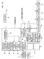
- Fig. 19 is a block diagram showing a construction of an ultrasonographic device of this embodiment.
- Fig. 20 is a block diagram showing a detail construction of a transmitted of this embodiment.
- Fig. 21 is a block diagram showing a detail construction of a code demodulator of this embodiment.
- This embodiment is different from the first embodiment in which a modulation waveform phase rotating unit 87 is provided between the modulation waveform selector 19 and the transmission pulse generator 21 and that a demodulation coefficient phase rotating unit 89 is provided between the demodulation coefficient selector 27 and demodulation filter 29. Therefore, the description of identical parts to those of the first embodiment is omitted herein, and differences will be described herein. Identical reference numerals are given to identical parts in the description.
- the ultrasonographic device of this embodiment includes the demodulation waveform phase rotating unit 87 between the modulation waveform selector 19 and transmission pulse generator 21 of the transmitter 3.
- the ultrasonographic device further includes the demodulation coefficient phase rotating unit 89 between the demodulation coefficient selector 27 and demodulation filter 29 of the code demodulator 11.
- the modulation waveform phase rotating unit 87 and the demodulation coefficient phase rotating unit 89 perform a phase rotation based on a desired frequency band.
- multiple modulation waveforms such as modulation waveforms relating to modulation codes A, B, -B and -A are selected by the modulation waveform selector 19.
- the selected multiple modulation waveforms are stored in the modulation waveform phase rotating unit 87.
- the stored modulation waveforms are loaded from the modulation waveform phase rotating unit 87 by the transmission pulse generator 21 in accordance with a predetermined transmission sequence.
- the loaded modulation waveform is output to the power amplifier 23.
- multiple demodulation encoding coefficients such as demodulation codes corresponding to modulation codes A, B, - B and -A are selected by the demodulation coefficient selector 27.
- the selected demodulation encoding coefficients are stored in the demodulation coefficient phase rotating unit 89.
- the stored demodulation encoding coefficients are loaded from the demodulation coefficient phase rotating unit 89 in accordance with a predetermined transmission sequence.
- the loaded demodulation encoding coefficients are output to the demodulation filter 29.
- modulation waveforms based on modulation codes are rotated in phase and output by the modulation waveform phase rotating unit 87. Furthermore, demodulation encoding coefficients based on modulation codes are rotated in phase and output by the demodulation coefficient phase rotating unit 89.
- computing loads can be advantageously reduced since no modulation waveform or demodulation encoding coefficient is required to calculate every encoding transmission/reception in addition to the same advantages as the advantages of the first embodiment.
- modulation codes in an encoding set are modulation codes A and B and modulation codes in the reverse encoding set are modulation codes -B and -A, for example.
- the modulation codes in the reverse encoding set have the opposite arrangement order of and phases resulting from a rotation of the phases of the modulation codes in the encoding set.
- the modulation codes in the encoding set may be modulation codes A and B
- the modulation codes in the reverse encoding set may be modulation codes B and A.
- the code construction the time side lobe due to a body motion of a subject can be reduced.
- each of embodiments and examples of the present invention are applicable in any manner except that the phases of modulation codes in the reverse encoding set are rotated. Notably, the same is true for cases in which three or more modulation codes are included in an encoding set and the reverse encoding set.
- each of the embodiments and examples of the present invention is applicable to a case in which modulation codes in an encoding set are modulation codes A and B and modulation codes in the reverse encoding set are modulation codes -A and -B.
- modulation codes in an encoding set are modulation codes A and B
- modulation codes in the reverse encoding set are modulation codes -A and -B.
- the time side lobe due to a body motion of a subject cannot be reduced, but the time side lobe due to nonlinearity of a medium within a subject can be reduced.
- the same is true for cases in which three or more modulation codes are included in an encoding set and the reverse encoding set.
Abstract
Description

Claims (20)
- An ultrasonographic method, comprising:a first encoding transmission/reception step for sequentially modulating, with an encoding set including a plurality of modulation codes in which at least two are in complementary relationship, and outputting a basic wave to a probe as an encoding drive signal and transmitting an ultrasonic beam and demodulating each reception signal output from the probe with demodulation codes corresponding to the modulation codes in the encoding set;a step for obtaining a first synthesis signal by synthesizing demodulation signals resulting from the demodulation in the first encoding transmission/reception step;a second encoding transmission/reception step for sequentially modulating, with a reverse encoding set including a plurality of modulation codes in reverse order of the modulation codes in the encoding set, and outputting a basic wave to the probe as an encoding drive signal and transmitting an ultrasonic beam and demodulating each reception signal output from the probe with demodulation codes corresponding to the modulation codes in the reverse encoding set;a step for obtaining a second synthesis signal by synthesizing demodulation signals resulting from the demodulation in the second encoding transmission/reception step;a step for obtaining a third synthesis signal by synthesizing the first synthesis signal and the second synthesis signal; anda step for reconstructing an ultrasonograph based on the third synthesis signal.
- The ultrasonographic method according to Claim 1, wherein the plurality of modulation codes in the reverse encoding set have phases resulting from a rotation of the phases of the modulation codes in the encoding set.
- The ultrasonographic method according to Claim 2, wherein the step for obtaining the first synthesis signal and the step for obtaining the second synthesis signal are performed after the first encoding transmission/reception step and the second encoding transmission/reception step.
- The ultrasonographic method according to Claim 2, wherein the first encoding transmission/reception step and the second encoding transmission/reception step are performed on different scan lines.
- The ultrasonographic method according to Claim 2, wherein an ultrasonograph is reconstructed by obtaining the third synthesis signal for each scan line of two different scan lines in the reverse order of performing the first encoding transmission/reception step and the second encoding transmission/reception step and synthesizing the two third synthesis signals.
- The ultrasonographic method according to Claim 2, wherein the first encoding transmission/reception step includes dividing and transmitting ultrasonic beams corresponding to the modulation codes in the encoding set to a plurality of first scan lines, and the second encoding transmission/reception step includes dividing and transmitting ultrasonic beams corresponding to the modulation codes in the reverse encoding set to a plurality of second scan lines, which are at least partially different from the plurality of first scan lines.
- The ultrasonographic method according to Claim 2, wherein, when the encoding set includes a first modulation code and a second modulation code, the reverse encoding set includes a third modulation code having the inverted polarity of that of the second modulation code and a fourth modulation code having the inverted polarity of that of the first modulation code in order.
- The ultrasonographic method according to Claim 2, wherein, when the encoding set includes first to third modulation codes, the reverse encoding set includes a fourth modulation code having the inverted polarity of that of the third modulation code, a fifth modulation code having the inverted polarity of that of the second modulation code and a sixth modulation code having the inverted polarity of that of the first modulation code in order.
- The ultrasonographic method according to Claim 2, wherein, when the encoding set includes first to fourth modulation codes, the reverse encoding set includes a fifth modulation code having the inverted polarity of that of the fourth modulation code, a sixth modulation code having the inverted polarity of that of the third modulation code, a seventh modulation code having the inverted polarity of that of the second modulation code and an eighth modulation code having the inverted polarity of that of the first modulation code in order.
- The ultrasonographic method according to Claim 2, wherein, when each of the encoding set and reverse encoding set includes N modulation codes, the Mth modulation code in the reverse encoding set has the inverted polarity of that of the (N-M+1)th modulation code in the encoding set where N is a natural number equal to or higher than 5 and M is a natural number equal to or lower than N.
- The ultrasonographic method according to Claim 2, wherein the encoding set includes a pair of Golay codes.
- An ultrasonographic device, comprising a probe for transmitting/receiving an ultrasonic wave; transmitting means that outputs a drive signal for the probe; receiving means that processes a reception signal output from the probe; image processing means that reconstructs an ultrasonograph based on a synthesis signal output from the receiving means; display mean that displays the reconstructed ultrasonograph; and control means that controls the transmitting means, the receiving means, the image processing means and the display means,
wherein the transmitting means includes means that creates an encoding set consisting of a plurality of modulation codes in which at least two are in complementary relationship and a reverse encoding set consisting of a plurality of modulation codes in which the arrangement order of modulation codes of the encoding set is reversed and means that modulates a basic wave with information on the encoding set and the reverse encoding set and generates an encoding drive signal; and
the receiving means includes means that demodulates each reception signal corresponding to the encoding drive signal modulated with the encoding set with each demodulation code corresponding to each modulation code in the encoding set, means that synthesizes demodulated signals and generates a first synthesis signal, means that demodulates each reception signal corresponding to the encoding drive signal modulated with the reverse encoding set with each demodulation code corresponding to each modulation code in the reverse encoding set, means that synthesizes the demodulated signals and generates a second synthesis signal, and means that generates a third synthesis signal from the first synthesis signal and the second synthesis signal. - The ultrasonographic image according to Claim 12, wherein the plurality of modulation codes in the reverse encoding set have phases resulting from rotation of the phases of the modulation codes in the encoding set.
- The ultrasonographic image according to Claim 12, wherein the transmitting means transmits a plurality of first ultrasonic transmission beams from the probe to a first scan line by encoding drive signals corresponding to the encoding set and the reverse encoding set and transmits a plurality of second ultrasonic transmission beams from the probe to a second scan line, which is different from the first scan line, by encoding drive signals sequentially modulated in interchanged set order of the encoding set and the reverse encoding set; and
the receiving means demodulates and then synthesizes reception signals corresponding to the first ultrasonic transmission beams and reception signals corresponding to the second ultrasonic transmission beams. - The ultrasonographic device according to Claim 12, wherein the transmitting means transmits a plurality of first ultrasonic transmission beams from the probe to a first scan line by an encoding drive signal corresponding to the encoding set and transmits a plurality of second ultrasonic transmission beams from the probe to a second scan line, which is different from the first scan line, by an encoding drive signal corresponding to the reverse encoding set; and
the receiving means demodulates and then synthesizes reception signals corresponding to the first ultrasonic transmission beams and reception signals corresponding to the second ultrasonic transmission beams. - The ultrasonographic device according to Claim 12, wherein the transmitting means divides and transmits a plurality of ultrasonic transmission beams to be transmitted from the probe by encoding drive signals corresponding to the encoding set and the reverse encoding set to a plurality of scan lines; and
the receiving means demodulates and then synthesizes reception signals corresponding to the ultrasonic transmission beams. - The ultrasonographic device according to Claim 12, wherein, when a plurality of ultrasonic transmission beams to be transmitted from the probe by encoding drive signals corresponding to the encoding set and the reverse encoding set are divided and transmitted to a plurality of scan lines, the transmitting means divides and transmits scan ultrasonic beams to the plurality of scan lines; and
the receiving means includes correlation determining means that analyzes a correlation between reception signals corresponding to the scan ultrasonic beams and obtains a spatial correlation of the subject and determines the number of scan lines for dividing the plurality of ultrasonic transmission beams based on the spatial correlation. - The ultrasonographic device according to Claim 12, wherein, when a plurality of ultrasonic transmission beams to be transmitted from the probe by encoding drive signals corresponding to the encoding set and the reverse encoding set are repeatedly transmitted to scan lines, the transmitting means repeatedly transmits scan ultrasonic beams to the scan lines; and
the receiving means includes correlation determining means that analyzes a correlation between reception signals corresponding to the scan ultrasonic beams and obtains a time correlation of the subject and determines at least one of the number of times of transmissions of ultrasonic transmission beams to be transmitted to the scan lines and a transmission timing based on the time correlation. - The ultrasonographic device according to Claim 12, wherein the transmitting means has modulation waveform phase rotating means that rotates the phase of the modulation wave and rotates the phase of the modulation waveform in accordance with each modulation encoding coefficient of each of the modulation codes.
- The ultrasonographic device according to Claim 12, wherein the receiving means has demodulation encoding coefficient phase rotating means that rotates the phase of each demodulation encoding coefficient of each of the demodulation codes and performs demodulation based on the phase-rotated demodulation encoding coefficient.
Applications Claiming Priority (3)
| Application Number | Priority Date | Filing Date | Title |
|---|---|---|---|
| JP2003001336A JP4269145B2 (en) | 2003-01-07 | 2003-01-07 | Ultrasonic diagnostic equipment |
| JP2003001336 | 2003-01-07 | ||
| PCT/JP2003/016935 WO2004060167A1 (en) | 2003-01-07 | 2003-12-26 | Ultrasonographic method and ultrasonographic device |
Publications (3)
| Publication Number | Publication Date |
|---|---|
| EP1582149A1 true EP1582149A1 (en) | 2005-10-05 |
| EP1582149A4 EP1582149A4 (en) | 2006-05-24 |
| EP1582149B1 EP1582149B1 (en) | 2010-03-24 |
Family
ID=32708806
Family Applications (1)
| Application Number | Title | Priority Date | Filing Date |
|---|---|---|---|
| EP03786362A Expired - Fee Related EP1582149B1 (en) | 2003-01-07 | 2003-12-26 | Ultrasonographic method and ultrasonographic device |
Country Status (6)
| Country | Link |
|---|---|
| US (1) | US7354400B2 (en) |
| EP (1) | EP1582149B1 (en) |
| JP (1) | JP4269145B2 (en) |
| CN (1) | CN100475148C (en) |
| DE (1) | DE60331861D1 (en) |
| WO (1) | WO2004060167A1 (en) |
Cited By (1)
| Publication number | Priority date | Publication date | Assignee | Title |
|---|---|---|---|---|
| EP2133026A1 (en) * | 2007-04-24 | 2009-12-16 | Panasonic Corporation | Ultrasonographic device |
Families Citing this family (38)
| Publication number | Priority date | Publication date | Assignee | Title |
|---|---|---|---|---|
| US7311709B2 (en) * | 2001-10-22 | 2007-12-25 | Surgrx, Inc. | Electrosurgical instrument and method of use |
| US8075558B2 (en) * | 2002-04-30 | 2011-12-13 | Surgrx, Inc. | Electrosurgical instrument and method |
| US20050096544A1 (en) * | 2003-10-30 | 2005-05-05 | Xiaohui Hao | Method and apparatus for single transmission Golay coded excitation |
| WO2005058167A2 (en) * | 2003-12-02 | 2005-06-30 | Hitachi Medical Corp | Ultrasonographic device |
| US7955331B2 (en) * | 2004-03-12 | 2011-06-07 | Ethicon Endo-Surgery, Inc. | Electrosurgical instrument and method of use |
| EP1776817B1 (en) * | 2004-07-29 | 2009-03-25 | Nxp B.V. | Enhanced bit mapping for digital interface of a wireless communication equipment in multi-time slot and multi-mode operation |
| US7654148B2 (en) * | 2005-06-22 | 2010-02-02 | Lockheed Martin Corporation | Ultrasound communication system for metal structure and related methods |
| US20070239002A1 (en) * | 2005-12-28 | 2007-10-11 | Alam Sheikh K | Superfast, High-Resolution Ultrasonic Imaging Using Coded Excitation |
| CN101411625B (en) * | 2007-10-15 | 2012-07-25 | 深圳迈瑞生物医疗电子股份有限公司 | Method for modulating and transmitting ultrasonic system bipolar pulse |
| US20100036370A1 (en) * | 2008-08-07 | 2010-02-11 | Al Mirel | Electrosurgical instrument jaw structure with cutting tip |
| US8855101B2 (en) | 2010-03-09 | 2014-10-07 | The Nielsen Company (Us), Llc | Methods, systems, and apparatus to synchronize actions of audio source monitors |
| US8700137B2 (en) | 2012-08-30 | 2014-04-15 | Alivecor, Inc. | Cardiac performance monitoring system for use with mobile communications devices |
| US8509882B2 (en) | 2010-06-08 | 2013-08-13 | Alivecor, Inc. | Heart monitoring system usable with a smartphone or computer |
| US9351654B2 (en) | 2010-06-08 | 2016-05-31 | Alivecor, Inc. | Two electrode apparatus and methods for twelve lead ECG |
| DE102010033210A1 (en) * | 2010-08-03 | 2012-02-09 | Valeo Schalter Und Sensoren Gmbh | Method for operating an ultrasonic sensor of a driver assistance system in a motor vehicle, driver assistance system and motor vehicle |
| TWI551071B (en) * | 2010-12-16 | 2016-09-21 | 李百祺 | Wireless power transmission system, wireless power transmitting apparatus and wireless power receiving apparatus |
| KR101460692B1 (en) | 2011-06-09 | 2014-11-13 | 삼성전자주식회사 | Apparatus for driving 2 dimensional transducer-array, medical imaging system and method for driving 2 dimensional transducer-array |
| US8939909B2 (en) | 2011-10-28 | 2015-01-27 | Decision Sciences International Corporation | Spread spectrum coded waveforms in ultrasound imaging |
| US9254095B2 (en) | 2012-11-08 | 2016-02-09 | Alivecor | Electrocardiogram signal detection |
| WO2014107700A1 (en) | 2013-01-07 | 2014-07-10 | Alivecor, Inc. | Methods and systems for electrode placement |
| US9254092B2 (en) | 2013-03-15 | 2016-02-09 | Alivecor, Inc. | Systems and methods for processing and analyzing medical data |
| US9247911B2 (en) | 2013-07-10 | 2016-02-02 | Alivecor, Inc. | Devices and methods for real-time denoising of electrocardiograms |
| JP2015037535A (en) * | 2013-07-16 | 2015-02-26 | コニカミノルタ株式会社 | Ultrasonic signal processor, ultrasonic signal processing method and computer-readable non-temporary recording medium |
| US9844359B2 (en) | 2013-09-13 | 2017-12-19 | Decision Sciences Medical Company, LLC | Coherent spread-spectrum coded waveforms in synthetic aperture image formation |
| WO2015084669A1 (en) | 2013-12-02 | 2015-06-11 | Board Of Trustees Of Michigan State University | Ultrasonic communication system |
| US9420956B2 (en) | 2013-12-12 | 2016-08-23 | Alivecor, Inc. | Methods and systems for arrhythmia tracking and scoring |
| JP6212638B2 (en) * | 2014-06-26 | 2017-10-11 | 株式会社日立製作所 | Ultrasonic imaging device |
| US9931157B2 (en) | 2014-09-15 | 2018-04-03 | Ethicon Llc | Methods and devices for creating thermal zones within an electrosurgical instrument |
| WO2016138257A1 (en) | 2015-02-25 | 2016-09-01 | Decision Sciences Medical Company, LLC | Acoustic signal transmission couplants and coupling mediums |
| ES2820923T3 (en) | 2015-05-13 | 2021-04-22 | Alivecor Inc | Mismatch monitoring |
| WO2017022540A1 (en) * | 2015-08-06 | 2017-02-09 | 株式会社日立製作所 | Ultrasound imaging apparatus and ultrasound imaging method |
| AU2016334258B2 (en) | 2015-10-08 | 2021-07-01 | Decision Sciences Medical Company, LLC | Acoustic orthopedic tracking system and methods |
| US10314645B2 (en) | 2016-03-16 | 2019-06-11 | Ethicon Llc | Surgical end effectors with increased stiffness |
| CN109475386B (en) * | 2016-06-30 | 2021-10-26 | 皇家飞利浦有限公司 | Internal device tracking system and method of operating the same |
| US10727923B2 (en) * | 2016-10-24 | 2020-07-28 | RF Pixels, Inc. | Multi-antenna beam forming and spatial multiplexing transceiver |
| US11154274B2 (en) | 2019-04-23 | 2021-10-26 | Decision Sciences Medical Company, LLC | Semi-rigid acoustic coupling articles for ultrasound diagnostic and treatment applications |
| JP2023549818A (en) | 2020-11-13 | 2023-11-29 | ディスィジョン サイエンシズ メディカル カンパニー,エルエルシー | System and method for synthetic aperture ultrasound imaging of objects |
| CN114137082B (en) * | 2021-11-26 | 2022-06-28 | 中国科学院合肥物质科学研究院 | Automatic ultrasonic imaging detection method and system for six-axis mechanical arm |
Citations (6)
| Publication number | Priority date | Publication date | Assignee | Title |
|---|---|---|---|---|
| US4937580A (en) * | 1988-05-19 | 1990-06-26 | Trustees Of Dartmouth College | Geophysical radar apparatus and method |
| EP0952461A2 (en) * | 1998-04-20 | 1999-10-27 | General Electric Company | Ultrasonic beamforming with improved signal-to-noise ratio using orthogonal complementary sets |
| US20020091318A1 (en) * | 2001-01-11 | 2002-07-11 | General Electric Company | Harmonic golay-coded excitation with differential pulsing for diagnostic ultrasound imaging |
| US20020091317A1 (en) * | 2001-01-08 | 2002-07-11 | Chiao Richard Yung | Method and apparatus using golay-coded excitation for echocardiology |
| KR20020083011A (en) * | 2001-04-25 | 2002-11-01 | 주식회사 메디슨 | Ultrasound imaging method and apparatus using orthogonal golay codes |
| US20030018259A1 (en) * | 2001-07-03 | 2003-01-23 | Tetsuya Kawagishi | Ultrasound diagnostic apparatus |
Family Cites Families (2)
| Publication number | Priority date | Publication date | Assignee | Title |
|---|---|---|---|---|
| JPH01303135A (en) * | 1988-05-31 | 1989-12-07 | Yokogawa Medical Syst Ltd | Dispersion compressing system pulse echo system transmitting receiving device |
| JP3222648B2 (en) | 1993-08-25 | 2001-10-29 | ジーイー横河メディカルシステム株式会社 | Medical ultrasonic dispersion compression transmission / reception method and medical ultrasonic dispersion compression transmission / reception device |
-
2003
- 2003-01-07 JP JP2003001336A patent/JP4269145B2/en not_active Expired - Fee Related
- 2003-12-26 US US10/541,452 patent/US7354400B2/en not_active Expired - Fee Related
- 2003-12-26 DE DE60331861T patent/DE60331861D1/en not_active Expired - Lifetime
- 2003-12-26 WO PCT/JP2003/016935 patent/WO2004060167A1/en active Application Filing
- 2003-12-26 CN CNB2003801101300A patent/CN100475148C/en not_active Expired - Fee Related
- 2003-12-26 EP EP03786362A patent/EP1582149B1/en not_active Expired - Fee Related
Patent Citations (6)
| Publication number | Priority date | Publication date | Assignee | Title |
|---|---|---|---|---|
| US4937580A (en) * | 1988-05-19 | 1990-06-26 | Trustees Of Dartmouth College | Geophysical radar apparatus and method |
| EP0952461A2 (en) * | 1998-04-20 | 1999-10-27 | General Electric Company | Ultrasonic beamforming with improved signal-to-noise ratio using orthogonal complementary sets |
| US20020091317A1 (en) * | 2001-01-08 | 2002-07-11 | Chiao Richard Yung | Method and apparatus using golay-coded excitation for echocardiology |
| US20020091318A1 (en) * | 2001-01-11 | 2002-07-11 | General Electric Company | Harmonic golay-coded excitation with differential pulsing for diagnostic ultrasound imaging |
| KR20020083011A (en) * | 2001-04-25 | 2002-11-01 | 주식회사 메디슨 | Ultrasound imaging method and apparatus using orthogonal golay codes |
| US20030018259A1 (en) * | 2001-07-03 | 2003-01-23 | Tetsuya Kawagishi | Ultrasound diagnostic apparatus |
Non-Patent Citations (2)
| Title |
|---|
| LEE ET AL: "Golay Codes for Simultaneous Multi-Mode Operation in Phased Arrays" PROCEEDINGS OF THE ULTRASONICS SYMPOSIUM. SAN DIEGO, OCT. 27 - 29, 1982, NEW YORK, IEEE, US, vol. VOL. 2, 27 October 1982 (1982-10-27), pages 821-825, XP002117286 * |
| See also references of WO2004060167A1 * |
Cited By (2)
| Publication number | Priority date | Publication date | Assignee | Title |
|---|---|---|---|---|
| EP2133026A1 (en) * | 2007-04-24 | 2009-12-16 | Panasonic Corporation | Ultrasonographic device |
| EP2133026A4 (en) * | 2007-04-24 | 2012-08-22 | Panasonic Corp | Ultrasonographic device |
Also Published As
| Publication number | Publication date |
|---|---|
| CN1756509A (en) | 2006-04-05 |
| WO2004060167A1 (en) | 2004-07-22 |
| US20060173305A1 (en) | 2006-08-03 |
| DE60331861D1 (en) | 2010-05-06 |
| EP1582149B1 (en) | 2010-03-24 |
| JP2004209087A (en) | 2004-07-29 |
| US7354400B2 (en) | 2008-04-08 |
| EP1582149A4 (en) | 2006-05-24 |
| CN100475148C (en) | 2009-04-08 |
| JP4269145B2 (en) | 2009-05-27 |
Similar Documents
| Publication | Publication Date | Title |
|---|---|---|
| EP1582149B1 (en) | Ultrasonographic method and ultrasonographic device | |
| US6056693A (en) | Ultrasound imaging with synthetic transmit focusing | |
| US9198636B2 (en) | Continuous transmit focusing method and apparatus for ultrasound imaging system | |
| JP5238692B2 (en) | Retrospective and dynamic transmission focusing for spatial compounding | |
| US20060173313A1 (en) | Coherence factor adaptive ultrasound imaging | |
| US9465101B2 (en) | Aberration correction with broad transmit beams in medical ultrasound | |
| JP2006025905A (en) | Ultrasonic transmitting and receiving apparatus | |
| JP2009006168A (en) | Ultrasonic diagnosis device | |
| US20070083109A1 (en) | Adaptive line synthesis for ultrasound | |
| JP3884370B2 (en) | Ultrasonic diagnostic equipment | |
| JP2006271557A (en) | Ultrasonic diagnostic apparatus | |
| US20110282204A1 (en) | Ultrasonic diagnostic apparatus | |
| JP2002034985A (en) | Ultrasonograph | |
| JP2003339698A (en) | Ultrasonic diagnostic equipment | |
| JP2004113693A (en) | Ultrasonic imaging instrument and ultrasonic imaging method | |
| JP4490128B2 (en) | Ultrasonic diagnostic equipment | |
| JPH10290799A (en) | Ultrasonograph | |
| JP4666815B2 (en) | Ultrasonic diagnostic equipment | |
| JP2005095576A (en) | Ultrasonic diagnostic apparatus | |
| JP2002186615A (en) | Ultrasonic daignostic device | |
| JP2011218049A (en) | Ultrasonic diagnostic apparatus | |
| JPH08173431A (en) | Ultrasonic diagnostic device | |
| KR101510678B1 (en) | Method for Forming Harmonic Image, Ultrasound Medical Apparatus Therefor | |
| JPH0542157A (en) | Ultrasonic diagnostic device | |
| JPH09133761A (en) | Pulse compression device and ultrasonic diagnostic device |
Legal Events
| Date | Code | Title | Description |
|---|---|---|---|
| PUAI | Public reference made under article 153(3) epc to a published international application that has entered the european phase |
Free format text: ORIGINAL CODE: 0009012 |
|
| 17P | Request for examination filed |
Effective date: 20050802 |
|
| AK | Designated contracting states |
Kind code of ref document: A1 Designated state(s): AT BE BG CH CY CZ DE DK EE ES FI FR GB GR HU IE IT LI LU MC NL PT RO SE SI SK TR |
|
| RBV | Designated contracting states (corrected) |
Designated state(s): DE FR GB IT NL |
|
| RIC1 | Information provided on ipc code assigned before grant |
Ipc: G01S 7/52 20060101AFI20060330BHEP Ipc: G01S 15/89 20060101ALI20060330BHEP Ipc: A61B 8/00 20060101ALI20060330BHEP |
|
| A4 | Supplementary search report drawn up and despatched |
Effective date: 20060407 |
|
| RIN1 | Information on inventor provided before grant (corrected) |
Inventor name: ASAFUSA, KATSUNORI Inventor name: KANDA, HIROSHI |
|
| 17Q | First examination report despatched |
Effective date: 20080819 |
|
| GRAP | Despatch of communication of intention to grant a patent |
Free format text: ORIGINAL CODE: EPIDOSNIGR1 |
|
| GRAS | Grant fee paid |
Free format text: ORIGINAL CODE: EPIDOSNIGR3 |
|
| GRAA | (expected) grant |
Free format text: ORIGINAL CODE: 0009210 |
|
| AK | Designated contracting states |
Kind code of ref document: B1 Designated state(s): DE FR GB IT NL |
|
| REG | Reference to a national code |
Ref country code: GB Ref legal event code: FG4D |
|
| REF | Corresponds to: |
Ref document number: 60331861 Country of ref document: DE Date of ref document: 20100506 Kind code of ref document: P |
|
| REG | Reference to a national code |
Ref country code: NL Ref legal event code: T3 |
|
| PLBE | No opposition filed within time limit |
Free format text: ORIGINAL CODE: 0009261 |
|
| STAA | Information on the status of an ep patent application or granted ep patent |
Free format text: STATUS: NO OPPOSITION FILED WITHIN TIME LIMIT |
|
| 26N | No opposition filed |
Effective date: 20101228 |
|
| PGFP | Annual fee paid to national office [announced via postgrant information from national office to epo] |
Ref country code: NL Payment date: 20131206 Year of fee payment: 11 Ref country code: IT Payment date: 20131217 Year of fee payment: 11 |
|
| PGFP | Annual fee paid to national office [announced via postgrant information from national office to epo] |
Ref country code: GB Payment date: 20141124 Year of fee payment: 12 |
|
| PGFP | Annual fee paid to national office [announced via postgrant information from national office to epo] |
Ref country code: FR Payment date: 20141124 Year of fee payment: 12 |
|
| REG | Reference to a national code |
Ref country code: NL Ref legal event code: V1 Effective date: 20150701 |
|
| REG | Reference to a national code |
Ref country code: NL Ref legal event code: V1 Effective date: 20150701 |
|
| PG25 | Lapsed in a contracting state [announced via postgrant information from national office to epo] |
Ref country code: NL Free format text: LAPSE BECAUSE OF NON-PAYMENT OF DUE FEES Effective date: 20150701 |
|
| PG25 | Lapsed in a contracting state [announced via postgrant information from national office to epo] |
Ref country code: IT Free format text: LAPSE BECAUSE OF NON-PAYMENT OF DUE FEES Effective date: 20141226 |
|
| PGFP | Annual fee paid to national office [announced via postgrant information from national office to epo] |
Ref country code: DE Payment date: 20151230 Year of fee payment: 13 |
|
| GBPC | Gb: european patent ceased through non-payment of renewal fee |
Effective date: 20151226 |
|
| REG | Reference to a national code |
Ref country code: FR Ref legal event code: ST Effective date: 20160831 |
|
| PG25 | Lapsed in a contracting state [announced via postgrant information from national office to epo] |
Ref country code: GB Free format text: LAPSE BECAUSE OF NON-PAYMENT OF DUE FEES Effective date: 20151226 |
|
| PG25 | Lapsed in a contracting state [announced via postgrant information from national office to epo] |
Ref country code: FR Free format text: LAPSE BECAUSE OF NON-PAYMENT OF DUE FEES Effective date: 20151231 |
|
| REG | Reference to a national code |
Ref country code: DE Ref legal event code: R119 Ref document number: 60331861 Country of ref document: DE |
|
| PG25 | Lapsed in a contracting state [announced via postgrant information from national office to epo] |
Ref country code: DE Free format text: LAPSE BECAUSE OF NON-PAYMENT OF DUE FEES Effective date: 20170701 |