EP1619476A2 - Encoder and signal adjustment method for the same - Google Patents
Encoder and signal adjustment method for the same Download PDFInfo
- Publication number
- EP1619476A2 EP1619476A2 EP05253769A EP05253769A EP1619476A2 EP 1619476 A2 EP1619476 A2 EP 1619476A2 EP 05253769 A EP05253769 A EP 05253769A EP 05253769 A EP05253769 A EP 05253769A EP 1619476 A2 EP1619476 A2 EP 1619476A2
- Authority
- EP
- European Patent Office
- Prior art keywords
- signal
- encoder
- error
- analog signal
- detector
- Prior art date
- Legal status (The legal status is an assumption and is not a legal conclusion. Google has not performed a legal analysis and makes no representation as to the accuracy of the status listed.)
- Granted
Links
Images


Classifications
-
- G—PHYSICS
- G01—MEASURING; TESTING
- G01D—MEASURING NOT SPECIALLY ADAPTED FOR A SPECIFIC VARIABLE; ARRANGEMENTS FOR MEASURING TWO OR MORE VARIABLES NOT COVERED IN A SINGLE OTHER SUBCLASS; TARIFF METERING APPARATUS; MEASURING OR TESTING NOT OTHERWISE PROVIDED FOR
- G01D18/00—Testing or calibrating apparatus or arrangements provided for in groups G01D1/00 - G01D15/00
- G01D18/001—Calibrating encoders
-
- G—PHYSICS
- G01—MEASURING; TESTING
- G01D—MEASURING NOT SPECIALLY ADAPTED FOR A SPECIFIC VARIABLE; ARRANGEMENTS FOR MEASURING TWO OR MORE VARIABLES NOT COVERED IN A SINGLE OTHER SUBCLASS; TARIFF METERING APPARATUS; MEASURING OR TESTING NOT OTHERWISE PROVIDED FOR
- G01D5/00—Mechanical means for transferring the output of a sensing member; Means for converting the output of a sensing member to another variable where the form or nature of the sensing member does not constrain the means for converting; Transducers not specially adapted for a specific variable
- G01D5/12—Mechanical means for transferring the output of a sensing member; Means for converting the output of a sensing member to another variable where the form or nature of the sensing member does not constrain the means for converting; Transducers not specially adapted for a specific variable using electric or magnetic means
- G01D5/244—Mechanical means for transferring the output of a sensing member; Means for converting the output of a sensing member to another variable where the form or nature of the sensing member does not constrain the means for converting; Transducers not specially adapted for a specific variable using electric or magnetic means influencing characteristics of pulses or pulse trains; generating pulses or pulse trains
- G01D5/24409—Interpolation using memories
-
- G—PHYSICS
- G01—MEASURING; TESTING
- G01D—MEASURING NOT SPECIALLY ADAPTED FOR A SPECIFIC VARIABLE; ARRANGEMENTS FOR MEASURING TWO OR MORE VARIABLES NOT COVERED IN A SINGLE OTHER SUBCLASS; TARIFF METERING APPARATUS; MEASURING OR TESTING NOT OTHERWISE PROVIDED FOR
- G01D5/00—Mechanical means for transferring the output of a sensing member; Means for converting the output of a sensing member to another variable where the form or nature of the sensing member does not constrain the means for converting; Transducers not specially adapted for a specific variable
- G01D5/12—Mechanical means for transferring the output of a sensing member; Means for converting the output of a sensing member to another variable where the form or nature of the sensing member does not constrain the means for converting; Transducers not specially adapted for a specific variable using electric or magnetic means
- G01D5/244—Mechanical means for transferring the output of a sensing member; Means for converting the output of a sensing member to another variable where the form or nature of the sensing member does not constrain the means for converting; Transducers not specially adapted for a specific variable using electric or magnetic means influencing characteristics of pulses or pulse trains; generating pulses or pulse trains
- G01D5/24471—Error correction
- G01D5/2448—Correction of gain, threshold, offset or phase control
-
- G—PHYSICS
- G01—MEASURING; TESTING
- G01D—MEASURING NOT SPECIALLY ADAPTED FOR A SPECIFIC VARIABLE; ARRANGEMENTS FOR MEASURING TWO OR MORE VARIABLES NOT COVERED IN A SINGLE OTHER SUBCLASS; TARIFF METERING APPARATUS; MEASURING OR TESTING NOT OTHERWISE PROVIDED FOR
- G01D5/00—Mechanical means for transferring the output of a sensing member; Means for converting the output of a sensing member to another variable where the form or nature of the sensing member does not constrain the means for converting; Transducers not specially adapted for a specific variable
- G01D5/12—Mechanical means for transferring the output of a sensing member; Means for converting the output of a sensing member to another variable where the form or nature of the sensing member does not constrain the means for converting; Transducers not specially adapted for a specific variable using electric or magnetic means
- G01D5/244—Mechanical means for transferring the output of a sensing member; Means for converting the output of a sensing member to another variable where the form or nature of the sensing member does not constrain the means for converting; Transducers not specially adapted for a specific variable using electric or magnetic means influencing characteristics of pulses or pulse trains; generating pulses or pulse trains
- G01D5/24471—Error correction
- G01D5/2449—Error correction using hard-stored calibration data
Definitions
- the present invention relates to an encoder and a signal adjustment method for the encoder. More particularly, the present invention relates to an encoder that enables easy signal adjustment and is suitable for use in a separate type absolute (ABS) linear encoder in which a scale and a detection head are provided separately or rotary encoder, and also relates to a signal adjustment method for that encoder.
- ABS absolute
- An encoder for detecting a position from two-phase analog signals formed by a sine wave and a cosine wave generally includes an interpolation (division) circuit in order to detect a change of the position (the moving amount) that is smaller than a period of the signal, as described in Japanese Patent Laid-Open Publication No. Sho 54-19773.
- the encoder equally divides the signal period at a predetermined pitch so as to obtain resolution smaller than the signal period.
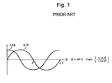
- the interpolation circuit calculates a phase angle ⁇ from the following expression, assuming that the sine wave (phase B) signal and the cosine wave (phase A) signal output from the encoder have a central voltage, amplitude, and a phase difference that are predetermined, as shown in Fig. 1.
- ⁇ arctan ⁇ ( sin ⁇ / cos ⁇ )
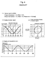
- Fig. 2 shows an example of the interpolation error in the case where the phase A signal has an offset of 0.2.
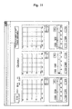
- Fig. 3 shows an example of the interpolation error in the case where the amplitudes of the phase A signal and the phase B signal are 1.0 and 1.2, respectively. That is, Fig.
- Fig. 3 shows a case where there is an amplitude difference between the phase A signal and the phase B signal.
- Fig. 4 shows an example of the interpolation error in the case where the phase B signal has a phase error of 10°.
- Fig. 5 shows an example of the interpolation error in the case where the phase A signal has the amplitude of 1.0 and the offset of 0.05 and the phase B signal has the amplitude of 0.95, the offset of -0.05 and the phase error of -5°. That is, Fig. 5 shows the case where the offset, the amplitude difference, and the phase error occur at the same time.
- a signal from the encoder it is necessary to adjust a signal from the encoder to have a central voltage, amplitude, and a phase difference that are predetermined, while observing the signal (e.g., a Lissajous waveform of the phase A signal and the phase B signal) on an oscilloscope.
- an encoder which includes a comparator for determining whether or not a signal having a predetermined level is obtained and outputting a determination result indicating that the determined signal is not an optimum signal inside (or outside) the encoder, as proposed in Japanese Patent No. 3202316. In this case, it is possible to confirm whether or not a predetermined signal is obtained, without using the oscilloscope.
- the encoder described in Japanese Patent No. 3202316 does not have a self-adjustment function. Therefore, in the case where a range of a signal level in which the comparator determines the signal as the optimum signal is made smaller, mechanical adjustment during attachment of the encoder becomes more difficult. On the other hand, in the case where the above range is made larger, a tolerance of a signal error also becomes larger, resulting in increase in the interpolation error.
- an ABS encoder that can detect an absolute position is widely used in machine tool or industrial machinery that includes an encoder for the reasons that (1) the ABS encoder does not require zero return at starting and (2) the ABS encoder does not require a magnetic-pole detector of a linear motor when the encoder is used for feed-back of the linear motor, and other reasons.
- the ABS encoder includes a multi-track encoder, and synthesizes signals obtained from multiple tracks so as to obtain the absolute position.
- Synthesis of the signals from the multiple tracks uses a CPU.
- An encoder including the CPU therein has been commonly used.
- the present invention aims to overcome the aforementioned problems of the conventional techniques. It is an object of the present invention to provide an encoder including a CPU therein, that enables easy signal adjustment so as to obtain an optimum signal to be performed without making a Lissajous waveform close to a perfect circle while observing a display screen of an oscilloscope, or providing a comparator for outputting a comparison result indicating that a signal of the encoder falls within a predetermined range or the like in the encoder.
- an encoder comprises: a detector; means for performing A/D conversion for an analog signal having at least two phases, the signal being output from the detector; means for correcting an error of the analog signal; an interpolation circuit for performing interpolation from a result of A/D conversion of the analog signal that is corrected; means for storing correction data; and central processing means having communication means.
- the encoder may send the result of A/D conversion of the analog signal to an external device by the communication means; the external device may detect the error of the signal from a predetermined value and send the error to the encoder by the communication means; and the encoder may perform interpolation for which error correction is performed by using the received correction data.
- an encoder comprises: a detector; means for performing A/D conversion for an analog signal having at least two phases, the analog signal being output from the detector; means for detecting an error of the analog signal; means for correcting the error of the analog signal; an interpolation circuit for performing interpolation from a result of A/D conversion of the analog signal that is corrected; means for storing correction data; and central processing means having communication means.
- the encoder may send the result of A/D conversion of the analog signal after correction to an external device by the communication means, and the external device may display and determine the corrected signal.
- the present invention it is possible to perform signal adjustment with high precision without using an oscilloscope. Moreover, a status of signal adjustment can be confirmed in a non-stepped manner, not by a stepped indication using LEDs as described in Japanese Patent No. 3202316. Furthermore, it is possible to confirm fine data, instead of a result of rough adjustment. Therefore, optimum adjustment and confirmation are possible.
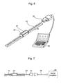
- the first embodiment of the present invention mainly includes: a scale base 10 attached to one portion of a machine (not shown), that is a scale-integrated type, for example; a detection head 20 that is fixed to another portion of the machine away from the scale base 10 by a predetermined distance and includes an LED 21 for indicating power-on and an alarm; a head cable 22 and an output connector 24 for connecting the detection head 20 to a feed-back cable 26 and a servo amplifier 28 of the machine after completion of adjustment, as shown in Fig. 7; and a personal computer (PC) 50 that is connected to the output connector 24 during adjustment, instead of the servo amplifier 28, as shown in Fig. 6.
- PC personal computer
- the detection head 20 includes a 3-track photoelectric type detector 30 having a light-emitting device and a light-receiving device, for example; an A/D converter 32 for performing A/D conversion for a sine wave signal and a cosine wave signal that form a two-phase analog signal output from the detector 30; an error correction circuit 34 for correcting an error of the aforementioned sine and cosine wave signals (a central voltage difference, an amplitude difference, and a phase difference); an interpolation circuit 36 for performing interpolation from the result of A/D conversion of signals corrected by the error correction circuit 34; communication means 38 for outputting an output of the interpolation circuit 36 to a control device (servo amplifier 28); a memory 40 for storing correction data; and a central processing unit (CPU) 42 having communication means 44 for communicating with the personal computer 50.
- a 3-track photoelectric type detector 30 having a light-emitting device and a light-receiving device, for example
- an A/D converter 32 for performing A/D conversion for
- the result of A/D conversion of the sine wave and the cosine wave by the A/D converter 32 (i.e., raw data) is sent to the personal computer 50 that is an external device by the communication means 44.
- the personal computer 50 detects an error of the sine wave signal and the cosine wave signal from a predetermined value.
- the error is then sent from the personal computer 50 to the detection head 20 by the communication means 44.
- the detection head 20 performs interpolation in which error correction is performed, by using correction data that is received and stored in the memory 40.
- the adjusted signal can be confirmed by displaying waveforms obtained by performing error correction for data of the sine wave and cosine wave that are sent from the detection head 20, on the personal computer 50.
- Step 100 the amplitude of a signal is checked in Step 100.
- Step 102 the procedure goes to Step 102 in which the position of the detection head 20 is mechanically adjusted.
- the adjustment of the signal amplitude may be achieved by additionally providing an amplifier 46 having a variable gain in the detection head 20 (as shown by a dashed line in Fig. 8) and adjusting the amplitude of a signal input to the detector 30 by using an output of the CPU 42. In this case, a range in which the amplitude can be adjusted can be made larger.
- Step 104 the procedure goes to Step 104 in which signal adjustment is performed. More specifically, while the detection head 20 is scanned over the entire length of the scale 10 in accordance with an instruction displayed on a display screen, for example, it is confirmed whether or not the LED 21 indicates an abnormal state. Based on a lighting state of the LED 21, necessary adjustment is performed.
- Step 106 When lighting of the LED 21 does not occur over the entire length of the scale 10 as a result of the adjustment, the signal amplitude is checked again in Step 106. When there is no problem, the signal adjustment is ended and the detection head 20 is fixed to the other portion of the machine at that position.
- Fig. 10 shows an exemplary display screen of the personal computer 50 during adjustment. This display screen corresponds to a case where there are three tracks on the scale.
- the detection head 20 is scanned with respect to the scale 10, Lissajous signals of the respective tracks are displayed.
- detection of the error of the sine and cosine wave signals is performed in the personal computer 50 externally provided.
- the structure of the detection head 20 is relatively simple.
- the error detection is not performed in the external device, but is performed in the detection head 20.
- error detection is performed in the CPU 42 in an arrangement similar to that in the first embodiment, as shown in Fig. 12.
- the present invention is applied to the separate type linear scale in which the scale and the detection head are provided separately in the aforementioned embodiments, an application of the present invention is not limited thereto.
- the present invention can be used for confirming an adjustment result in a separate type rotary encoder or an integrated type encoder.
- the number of the phases of the analog signal is not limited to two.
- the present invention can be applied to an encoder that outputs a three-phase analog signal with a phase difference of 120°.
- the three-phase analog signal is input to a known three-phase to two-phase conversion circuit so as to obtain a two-phase analog signal. Then, the thus obtained two-phase analog signal is processed in a similar manner to that described in the above embodiments.
Abstract
Description
- The present invention relates to an encoder and a signal adjustment method for the encoder. More particularly, the present invention relates to an encoder that enables easy signal adjustment and is suitable for use in a separate type absolute (ABS) linear encoder in which a scale and a detection head are provided separately or rotary encoder, and also relates to a signal adjustment method for that encoder.
- An encoder for detecting a position from two-phase analog signals formed by a sine wave and a cosine wave generally includes an interpolation (division) circuit in order to detect a change of the position (the moving amount) that is smaller than a period of the signal, as described in Japanese Patent Laid-Open Publication No. Sho 54-19773. The encoder equally divides the signal period at a predetermined pitch so as to obtain resolution smaller than the signal period.
- The interpolation circuit calculates a phase angle θ from the following expression, assuming that the sine wave (phase B) signal and the cosine wave (phase A) signal output from the encoder have a central voltage, amplitude, and a phase difference that are predetermined, as shown in Fig. 1.

- However, in the case where the central voltage, amplitude, or phase difference of at least one of the sine and cosine waves is not coincident with the predetermined value, the detected phase angle (the change amount of the position equal to or smaller than the signal period) does not have a constant pitch and an error (interpolation error) coincident with the signal period occurs, as shown in Figs. 2 to 5. Fig. 2 shows an example of the interpolation error in the case where the phase A signal has an offset of 0.2. Fig. 3 shows an example of the interpolation error in the case where the amplitudes of the phase A signal and the phase B signal are 1.0 and 1.2, respectively. That is, Fig. 3 shows a case where there is an amplitude difference between the phase A signal and the phase B signal. Fig. 4 shows an example of the interpolation error in the case where the phase B signal has a phase error of 10°. Fig. 5 shows an example of the interpolation error in the case where the phase A signal has the amplitude of 1.0 and the offset of 0.05 and the phase B signal has the amplitude of 0.95, the offset of -0.05 and the phase error of -5°. That is, Fig. 5 shows the case where the offset, the amplitude difference, and the phase error occur at the same time.
- Thus, in case of using a conventional encoder, it is necessary to adjust a signal from the encoder to have a central voltage, amplitude, and a phase difference that are predetermined, while observing the signal (e.g., a Lissajous waveform of the phase A signal and the phase B signal) on an oscilloscope.
- The adjustment while observing a display screen of the oscilloscope requires skills. In order to overcome this problem, an encoder is proposed which includes a comparator for determining whether or not a signal having a predetermined level is obtained and outputting a determination result indicating that the determined signal is not an optimum signal inside (or outside) the encoder, as proposed in Japanese Patent No. 3202316. In this case, it is possible to confirm whether or not a predetermined signal is obtained, without using the oscilloscope.
- However, the encoder described in Japanese Patent No. 3202316 does not have a self-adjustment function. Therefore, in the case where a range of a signal level in which the comparator determines the signal as the optimum signal is made smaller, mechanical adjustment during attachment of the encoder becomes more difficult. On the other hand, in the case where the above range is made larger, a tolerance of a signal error also becomes larger, resulting in increase in the interpolation error.
- On the other hand, an ABS encoder that can detect an absolute position is widely used in machine tool or industrial machinery that includes an encoder for the reasons that (1) the ABS encoder does not require zero return at starting and (2) the ABS encoder does not require a magnetic-pole detector of a linear motor when the encoder is used for feed-back of the linear motor, and other reasons. The ABS encoder includes a multi-track encoder, and synthesizes signals obtained from multiple tracks so as to obtain the absolute position.
- Synthesis of the signals from the multiple tracks uses a CPU. An encoder including the CPU therein has been commonly used.
- The present invention aims to overcome the aforementioned problems of the conventional techniques. It is an object of the present invention to provide an encoder including a CPU therein, that enables easy signal adjustment so as to obtain an optimum signal to be performed without making a Lissajous waveform close to a perfect circle while observing a display screen of an oscilloscope, or providing a comparator for outputting a comparison result indicating that a signal of the encoder falls within a predetermined range or the like in the encoder.
- In order to achieve the object described above, according to an aspect of the present invention, an encoder comprises: a detector; means for performing A/D conversion for an analog signal having at least two phases, the signal being output from the detector; means for correcting an error of the analog signal; an interpolation circuit for performing interpolation from a result of A/D conversion of the analog signal that is corrected; means for storing correction data; and central processing means having communication means.
- The encoder may send the result of A/D conversion of the analog signal to an external device by the communication means; the external device may detect the error of the signal from a predetermined value and send the error to the encoder by the communication means; and the encoder may perform interpolation for which error correction is performed by using the received correction data.
- In order to achieve the object described above, according to another aspect of the present invention, an encoder comprises: a detector; means for performing A/D conversion for an analog signal having at least two phases, the analog signal being output from the detector; means for detecting an error of the analog signal; means for correcting the error of the analog signal; an interpolation circuit for performing interpolation from a result of A/D conversion of the analog signal that is corrected; means for storing correction data; and central processing means having communication means.
- The encoder may send the result of A/D conversion of the analog signal after correction to an external device by the communication means, and the external device may display and determine the corrected signal.
- According to the present invention, it is possible to perform signal adjustment with high precision without using an oscilloscope. Moreover, a status of signal adjustment can be confirmed in a non-stepped manner, not by a stepped indication using LEDs as described in Japanese Patent No. 3202316. Furthermore, it is possible to confirm fine data, instead of a result of rough adjustment. Therefore, optimum adjustment and confirmation are possible.
- Especially, when the external device such as a personal computer is made to have a storage function, adjustment data of each encoder can be collectively managed.
- These and other novel features and advantages of the present invention will become apparent from the following detailed description of preferred embodiments.
- The preferred embodiments will be described with reference to the drawings, wherein like elements have been denoted throughout the figures with like reference numerals, and wherein;
- Fig. 1 is a diagram for explaining the principle of interpolation in an encoder;
- Fig. 2 is a diagram showing an effect of an offset in order to explain a problem of a conventional technique;
- Fig. 3 is a diagram showing an effect of an amplitude difference in order to explain the problem of the conventional technique;
- Fig. 4 is a diagram showing an effect of a phase error in order to explain the problem of the conventional technique;
- Fig. 5 is a diagram showing a composite effect of the offset, the amplitude difference, and the phase error in order to explain the problem of the conventional technique;
- Fig. 6 is a perspective view showing connection during signal adjustment in a first embodiment of the present invention;
- Fig. 7 is a front view showing final connection in the first embodiment;
- Fig. 8 is a block diagram of an internal structure according to the first embodiment;
- Fig. 9 is a flowchart of a procedure according to the first embodiment;
- Fig. 10 illustrates an exemplary display screen during adjustment in the first embodiment;
- Fig. 11 illustrates an exemplary display screen when a communication error occurs in the first embodiment; and
- Fig. 12 is a block diagram of an internal structure according to a second embodiment of the present invention.
- Preferred embodiments of the present invention will be now described in detail with reference to the accompanying drawings.
- The first embodiment of the present invention mainly includes: a
scale base 10 attached to one portion of a machine (not shown), that is a scale-integrated type, for example; adetection head 20 that is fixed to another portion of the machine away from thescale base 10 by a predetermined distance and includes anLED 21 for indicating power-on and an alarm; ahead cable 22 and anoutput connector 24 for connecting thedetection head 20 to a feed-back cable 26 and aservo amplifier 28 of the machine after completion of adjustment, as shown in Fig. 7; and a personal computer (PC) 50 that is connected to theoutput connector 24 during adjustment, instead of theservo amplifier 28, as shown in Fig. 6. - Fig. 8 shows details of the
detection head 20. As shown in Fig. 8, thedetection head 20 includes a 3-trackphotoelectric type detector 30 having a light-emitting device and a light-receiving device, for example; an A/D converter 32 for performing A/D conversion for a sine wave signal and a cosine wave signal that form a two-phase analog signal output from thedetector 30; anerror correction circuit 34 for correcting an error of the aforementioned sine and cosine wave signals (a central voltage difference, an amplitude difference, and a phase difference); aninterpolation circuit 36 for performing interpolation from the result of A/D conversion of signals corrected by theerror correction circuit 34; communication means 38 for outputting an output of theinterpolation circuit 36 to a control device (servo amplifier 28); amemory 40 for storing correction data; and a central processing unit (CPU) 42 having communication means 44 for communicating with thepersonal computer 50. - In the present embodiment, the result of A/D conversion of the sine wave and the cosine wave by the A/D converter 32 (i.e., raw data) is sent to the
personal computer 50 that is an external device by the communication means 44. Thepersonal computer 50 then detects an error of the sine wave signal and the cosine wave signal from a predetermined value. - The error is then sent from the
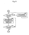
personal computer 50 to thedetection head 20 by the communication means 44. Thedetection head 20 performs interpolation in which error correction is performed, by using correction data that is received and stored in thememory 40. Thus, it is possible to perform optimum signal adjustment and confirmation. Moreover, the adjusted signal can be confirmed by displaying waveforms obtained by performing error correction for data of the sine wave and cosine wave that are sent from thedetection head 20, on thepersonal computer 50. - A specific procedure is shown in Fig. 9.
- First, the amplitude of a signal is checked in
Step 100. When a result of the check inStep 100 is No, i.e., it is determined that the signal amplitude is insufficient, the procedure goes toStep 102 in which the position of thedetection head 20 is mechanically adjusted. The adjustment of the signal amplitude may be achieved by additionally providing anamplifier 46 having a variable gain in the detection head 20 (as shown by a dashed line in Fig. 8) and adjusting the amplitude of a signal input to thedetector 30 by using an output of the CPU 42. In this case, a range in which the amplitude can be adjusted can be made larger. - When the result of the determination in
Step 100 is Yes, the procedure goes to Step 104 in which signal adjustment is performed. More specifically, while thedetection head 20 is scanned over the entire length of thescale 10 in accordance with an instruction displayed on a display screen, for example, it is confirmed whether or not theLED 21 indicates an abnormal state. Based on a lighting state of theLED 21, necessary adjustment is performed. - When lighting of the
LED 21 does not occur over the entire length of thescale 10 as a result of the adjustment, the signal amplitude is checked again inStep 106. When there is no problem, the signal adjustment is ended and thedetection head 20 is fixed to the other portion of the machine at that position. - Fig. 10 shows an exemplary display screen of the
personal computer 50 during adjustment. This display screen corresponds to a case where there are three tracks on the scale. When thedetection head 20 is scanned with respect to thescale 10, Lissajous signals of the respective tracks are displayed. - In this manner, it is possible to adjust and fix the
detection head 20 at an appropriate position with respect to thescale 10. In the case where no communication is performed because of a trouble in a power source or a connecting cable, a message indicating a communication error is displayed, as shown in Fig. 11. Thus, it is possible to urge an inspecting person to check the power source or the connecting cable. - In the present embodiment, detection of the error of the sine and cosine wave signals is performed in the
personal computer 50 externally provided. Thus, the structure of thedetection head 20 is relatively simple. - Next, the second embodiment of the present invention is described. In this embodiment, the error detection is not performed in the external device, but is performed in the
detection head 20. - In this embodiment, error detection is performed in the CPU 42 in an arrangement similar to that in the first embodiment, as shown in Fig. 12.
- Except for the above, the present embodiment is the same as the first embodiment. Therefore, detailed description of the present embodiment is omitted.
- In the present embodiment, not raw data but an error detected by the CPU 42 is sent from the communication means 44 to the
personal computer 50. Therefore, it is possible to easily determine whether or not optimum adjustment is performed by displaying and determining the corrected signal on thepersonal computer 50. - Although the present invention is applied to the separate type linear scale in which the scale and the detection head are provided separately in the aforementioned embodiments, an application of the present invention is not limited thereto. The present invention can be used for confirming an adjustment result in a separate type rotary encoder or an integrated type encoder.
- Moreover, the number of the phases of the analog signal is not limited to two. For example, the present invention can be applied to an encoder that outputs a three-phase analog signal with a phase difference of 120°. In this case, the three-phase analog signal is input to a known three-phase to two-phase conversion circuit so as to obtain a two-phase analog signal. Then, the thus obtained two-phase analog signal is processed in a similar manner to that described in the above embodiments.
Claims (10)
- An encoder comprising:a detector;means for performing A/D conversion for an analog signal having at least two phases, the signal being output from the detector;means for correcting an error of the analog signal;an interpolation circuit for performing interpolation from a result of A/D conversion of the analog signal that is corrected;means for storing correction data; andcentral processing means having communication means.
- The encoder according to claim 1, further comprising means for displaying a status of adjustment.
- An encoder according to claim 1 or claim 2, further comprising means for detecting an error of the analog signal.
- A method for adjusting a signal of an encoder, the encoder comprising:a detector;means for performing A/D conversion for an analog signal having at least two phases, the signal being output from the detector;means for correcting an error of the analog signal;an interpolation circuit for performing interpolation from a result of A/D conversion of the analog signal that is corrected;means for storing correction data; andcentral processing means having communication means, the method comprising the steps of:sending the result of A/D conversion of the analog signal to an external device by the communication means;allowing the external device to detect the error of the signal from a predetermined value and to send the error to the encoder by the communication means; andallowing the encoder to perform interpolation for which error correction is performed by using the received correction data.
- The method for adjusting a signal of an encoder according to claim 4, wherein the analog signal is a two-phase signal converted from a three-phase signal.
- The method for adjusting a signal of an encoder according to claim 4 or claim 5, wherein the external device is a personal computer.
- The method for adjusting a signal of an encoder according to any of claims 4 to 6, wherein the signal transmitted from the encoder and a waveform for which the error is corrected are displayed on the external device.
- The method for adjusting a signal of an encoder according to any of claims 4 to 7, wherein the signal adjustment is achieved by mechanically adjusting a position of the detector or adjusting a gain of an amplifier provided in the detector when an amplitude of the signal is insufficient; and
then adjusting the signal while scanning the detector. - The method for adjusting a signal of an encoder according to any of claims 4 to 8, wherein a message indicating a communication error is displayed when no communication is performed.
- A method according to any of claims 4 to 9, wherein the encoder further comprises means for detecting an error of the analog signal.
Applications Claiming Priority (1)
| Application Number | Priority Date | Filing Date | Title |
|---|---|---|---|
| JP2004182691A JP2006003307A (en) | 2004-06-21 | 2004-06-21 | Encoder, and signal regulation method therefor |
Publications (3)
| Publication Number | Publication Date |
|---|---|
| EP1619476A2 true EP1619476A2 (en) | 2006-01-25 |
| EP1619476A3 EP1619476A3 (en) | 2006-12-27 |
| EP1619476B1 EP1619476B1 (en) | 2011-05-11 |
Family
ID=35427937
Family Applications (1)
| Application Number | Title | Priority Date | Filing Date |
|---|---|---|---|
| EP05253769A Active EP1619476B1 (en) | 2004-06-21 | 2005-06-17 | Encoder and signal adjustment method for the same |
Country Status (4)
| Country | Link |
|---|---|
| US (1) | US7116252B2 (en) |
| EP (1) | EP1619476B1 (en) |
| JP (1) | JP2006003307A (en) |
| CN (1) | CN1712889B (en) |
Cited By (2)
| Publication number | Priority date | Publication date | Assignee | Title |
|---|---|---|---|---|
| DE102008050540B4 (en) * | 2008-10-06 | 2015-08-06 | Institut für Mikroelektronik- und Mechatronik-Systeme gGmbH | Arrangement for processing an analogue sensor output signal of at least one optical sensor |
| DE102007042073B4 (en) | 2007-09-05 | 2018-07-12 | Delta Electronics, Inc. | Apparatus and method for angle calculation for a three-phase optical encoder |
Families Citing this family (47)
| Publication number | Priority date | Publication date | Assignee | Title |
|---|---|---|---|---|
| GB0413827D0 (en) | 2004-06-21 | 2004-07-21 | Renishaw Plc | Scale reading apparatus |
| GB0428165D0 (en) * | 2004-12-23 | 2005-01-26 | Renishaw Plc | Position measurement |
| US8730031B2 (en) | 2005-04-28 | 2014-05-20 | Proteus Digital Health, Inc. | Communication system using an implantable device |
| EP3827747A1 (en) | 2005-04-28 | 2021-06-02 | Otsuka Pharmaceutical Co., Ltd. | Pharma-informatics system |
| US8912908B2 (en) | 2005-04-28 | 2014-12-16 | Proteus Digital Health, Inc. | Communication system with remote activation |
| US8802183B2 (en) | 2005-04-28 | 2014-08-12 | Proteus Digital Health, Inc. | Communication system with enhanced partial power source and method of manufacturing same |
| US7305773B2 (en) * | 2006-04-24 | 2007-12-11 | Rudy Hios | Hand tool |
| JP4119460B2 (en) * | 2006-06-21 | 2008-07-16 | ファナック株式会社 | Encoder output signal amplitude calculation device and encoder output signal amplitude calculation program |
| EP2063771A1 (en) | 2007-03-09 | 2009-06-03 | Proteus Biomedical, Inc. | In-body device having a deployable antenna |
| KR101184129B1 (en) * | 2008-06-05 | 2012-09-18 | 미쓰비시덴키 가부시키가이샤 | Optical encoder |
| KR101214453B1 (en) | 2008-08-13 | 2012-12-24 | 프로테우스 디지털 헬스, 인코포레이티드 | Ingestible circuitry |
| GB0819767D0 (en) * | 2008-10-28 | 2008-12-03 | Renishaw Plc | Absolute encoder setup indication |
| US9659423B2 (en) | 2008-12-15 | 2017-05-23 | Proteus Digital Health, Inc. | Personal authentication apparatus system and method |
| US9439566B2 (en) | 2008-12-15 | 2016-09-13 | Proteus Digital Health, Inc. | Re-wearable wireless device |
| JP5155223B2 (en) | 2009-03-17 | 2013-03-06 | 株式会社ミツトヨ | Absolute linear encoder and position adjustment method thereof |
| MX2011011506A (en) | 2009-04-28 | 2012-05-08 | Proteus Biomedical Inc | Highly reliable ingestible event markers and methods for using the same. |
| CN102101394B (en) * | 2009-12-17 | 2013-03-20 | 北大方正集团有限公司 | Method for accurately positioning absolute encoder and control device |
| JP5463898B2 (en) * | 2009-12-18 | 2014-04-09 | 日本精工株式会社 | How to adjust the resolver stator alone |
| AU2011210648B2 (en) | 2010-02-01 | 2014-10-16 | Otsuka Pharmaceutical Co., Ltd. | Data gathering system |
| JP5484980B2 (en) | 2010-03-24 | 2014-05-07 | 株式会社ミツトヨ | Optical encoder |
| WO2011127252A2 (en) | 2010-04-07 | 2011-10-13 | Proteus Biomedical, Inc. | Miniature ingestible device |
| EP2642983A4 (en) | 2010-11-22 | 2014-03-12 | Proteus Digital Health Inc | Ingestible device with pharmaceutical product |
| JP2013152204A (en) * | 2011-01-28 | 2013-08-08 | Nsk Ltd | Resolver digital converter matching circuit, resolver device, motor device, and motor drive unit |
| US9439599B2 (en) | 2011-03-11 | 2016-09-13 | Proteus Digital Health, Inc. | Wearable personal body associated device with various physical configurations |
| WO2015112603A1 (en) | 2014-01-21 | 2015-07-30 | Proteus Digital Health, Inc. | Masticable ingestible product and communication system therefor |
| US9756874B2 (en) | 2011-07-11 | 2017-09-12 | Proteus Digital Health, Inc. | Masticable ingestible product and communication system therefor |
| JP5932285B2 (en) * | 2011-10-14 | 2016-06-08 | キヤノン株式会社 | Encoder and device equipped with the same |
| TW201424689A (en) | 2012-07-23 | 2014-07-01 | Proteus Digital Health Inc | Techniques for manufacturing ingestible event markers comprising an ingestible component |
| BR112015006242A2 (en) * | 2012-09-21 | 2017-07-04 | Proteus Digital Health Inc | wireless wearable device, system and method |
| US9268909B2 (en) | 2012-10-18 | 2016-02-23 | Proteus Digital Health, Inc. | Apparatus, system, and method to adaptively optimize power dissipation and broadcast power in a power source for a communication device |
| US11149123B2 (en) | 2013-01-29 | 2021-10-19 | Otsuka Pharmaceutical Co., Ltd. | Highly-swellable polymeric films and compositions comprising the same |
| JP6037881B2 (en) * | 2013-02-14 | 2016-12-07 | 三菱重工工作機械株式会社 | Accuracy correction method for position detector |
| CN103175567B (en) * | 2013-03-01 | 2015-09-09 | 中国科学院长春光学精密机械与物理研究所 | A kind of on-line amending device of absolute grating ruler reading head parameter |
| JP6498177B2 (en) | 2013-03-15 | 2019-04-10 | プロテウス デジタル ヘルス, インコーポレイテッド | Identity authentication system and method |
| US10175376B2 (en) | 2013-03-15 | 2019-01-08 | Proteus Digital Health, Inc. | Metal detector apparatus, system, and method |
| US9796576B2 (en) | 2013-08-30 | 2017-10-24 | Proteus Digital Health, Inc. | Container with electronically controlled interlock |
| MX356850B (en) | 2013-09-20 | 2018-06-15 | Proteus Digital Health Inc | Methods, devices and systems for receiving and decoding a signal in the presence of noise using slices and warping. |
| US9577864B2 (en) | 2013-09-24 | 2017-02-21 | Proteus Digital Health, Inc. | Method and apparatus for use with received electromagnetic signal at a frequency not known exactly in advance |
| US10084880B2 (en) | 2013-11-04 | 2018-09-25 | Proteus Digital Health, Inc. | Social media networking based on physiologic information |
| CN107820673B (en) * | 2015-07-02 | 2021-07-16 | 株式会社富士 | Servo motor driving device |
| US11051543B2 (en) | 2015-07-21 | 2021-07-06 | Otsuka Pharmaceutical Co. Ltd. | Alginate on adhesive bilayer laminate film |
| JP6668082B2 (en) * | 2016-01-20 | 2020-03-18 | 日本電産サンキョー株式会社 | Encoder |
| CN109843149B (en) | 2016-07-22 | 2020-07-07 | 普罗秋斯数字健康公司 | Electromagnetic sensing and detection of ingestible event markers |
| JP2019535377A (en) | 2016-10-26 | 2019-12-12 | プロテウス デジタル ヘルス, インコーポレイテッド | Method for producing capsules with ingestible event markers |
| JP2017161553A (en) * | 2017-06-22 | 2017-09-14 | 株式会社リコー | Rotation angle detector, motor system, image processing device, and rotation angle detection method |
| JP6659656B2 (en) | 2017-12-01 | 2020-03-04 | ファナック株式会社 | Encoder and control system |
| JP6649419B2 (en) * | 2018-03-26 | 2020-02-19 | ファナック株式会社 | Encoder signal processing device and encoder |
Citations (4)
| Publication number | Priority date | Publication date | Assignee | Title |
|---|---|---|---|---|
| DE4443898A1 (en) | 1994-12-09 | 1996-06-13 | Heidenhain Gmbh Dr Johannes | Relative position of two objects measurement appts. |
| JP3202316B2 (en) | 1991-05-16 | 2001-08-27 | レニショウ トランスデューサ システムズ リミテッド | Read head |
| WO2003034000A1 (en) | 2001-10-19 | 2003-04-24 | Renishaw Plc | Interface for position determining device |
| US6639529B1 (en) | 2002-05-14 | 2003-10-28 | Mitutoyo Corporation | System and method for delay calibration in position encoders |
Family Cites Families (12)
| Publication number | Priority date | Publication date | Assignee | Title |
|---|---|---|---|---|
| DE2729697A1 (en) * | 1977-07-01 | 1979-01-04 | Heidenhain Gmbh Dr Johannes | METHOD OF INTERPOLATION |
| JP2754422B2 (en) * | 1990-07-18 | 1998-05-20 | 株式会社ニコン | Absolute encoder |
| US5506579A (en) * | 1991-06-06 | 1996-04-09 | Trj & Company | Absolute encoder using multiphase analog signals |
| JPH0567292A (en) * | 1991-09-10 | 1993-03-19 | Fujitsu Ltd | System for compensating measured value |
| JPH05296793A (en) * | 1992-04-21 | 1993-11-09 | Olympus Optical Co Ltd | Offset automatic regulator of encoder output signal |
| JPH07229757A (en) * | 1994-02-18 | 1995-08-29 | Canon Inc | Signal processing device, position detecting device and driving device |
| JPH08145719A (en) * | 1994-09-22 | 1996-06-07 | Canon Inc | Method for detecting position or angle |
| DE69613867T2 (en) * | 1995-01-30 | 2001-10-31 | Sony Prec Technology Inc | Interpolation device |
| WO1998021553A1 (en) * | 1996-11-11 | 1998-05-22 | Fanuc Ltd. | Interpolation circuit of encoder |
| JP4000629B2 (en) * | 1997-07-14 | 2007-10-31 | 松下電器産業株式会社 | Sensor with adjustment function |
| JP2000213959A (en) * | 1999-01-22 | 2000-08-04 | Takashi Katagiri | Position detecting device |
| JP2003035569A (en) * | 2001-07-25 | 2003-02-07 | Fuji Electric Co Ltd | Optical encoder |
-
2004
- 2004-06-21 JP JP2004182691A patent/JP2006003307A/en active Pending
-
2005
- 2005-06-14 US US11/151,286 patent/US7116252B2/en active Active
- 2005-06-15 CN CN2005100779219A patent/CN1712889B/en active Active
- 2005-06-17 EP EP05253769A patent/EP1619476B1/en active Active
Patent Citations (4)
| Publication number | Priority date | Publication date | Assignee | Title |
|---|---|---|---|---|
| JP3202316B2 (en) | 1991-05-16 | 2001-08-27 | レニショウ トランスデューサ システムズ リミテッド | Read head |
| DE4443898A1 (en) | 1994-12-09 | 1996-06-13 | Heidenhain Gmbh Dr Johannes | Relative position of two objects measurement appts. |
| WO2003034000A1 (en) | 2001-10-19 | 2003-04-24 | Renishaw Plc | Interface for position determining device |
| US6639529B1 (en) | 2002-05-14 | 2003-10-28 | Mitutoyo Corporation | System and method for delay calibration in position encoders |
Cited By (2)
| Publication number | Priority date | Publication date | Assignee | Title |
|---|---|---|---|---|
| DE102007042073B4 (en) | 2007-09-05 | 2018-07-12 | Delta Electronics, Inc. | Apparatus and method for angle calculation for a three-phase optical encoder |
| DE102008050540B4 (en) * | 2008-10-06 | 2015-08-06 | Institut für Mikroelektronik- und Mechatronik-Systeme gGmbH | Arrangement for processing an analogue sensor output signal of at least one optical sensor |
Also Published As
| Publication number | Publication date |
|---|---|
| JP2006003307A (en) | 2006-01-05 |
| US20050280563A1 (en) | 2005-12-22 |
| EP1619476A3 (en) | 2006-12-27 |
| EP1619476B1 (en) | 2011-05-11 |
| CN1712889A (en) | 2005-12-28 |
| CN1712889B (en) | 2011-05-11 |
| US7116252B2 (en) | 2006-10-03 |
Similar Documents
| Publication | Publication Date | Title |
|---|---|---|
| EP1619476B1 (en) | Encoder and signal adjustment method for the same | |
| US7797981B2 (en) | Position measuring device | |
| EP2343510B1 (en) | Rotary encoder | |
| US6922899B2 (en) | Rotary encoder | |
| KR102086357B1 (en) | Using Absolute Encoders for Motor Absolute position and Finding minimum Absolute Encoders Resolution | |
| KR890003031B1 (en) | Method and apparatus fpr calibrating a positioning system | |
| JP5079644B2 (en) | Position measuring device | |
| US8912929B2 (en) | Correction value derivation apparatus, displacement amount derivation apparatus, control apparatus, and correction value derivation method | |
| EP1876424B1 (en) | Displacement detecting encoder | |
| EP2365291A1 (en) | Photoelectric encoder | |
| EP0669517A2 (en) | Signal processing apparatus and displacement detecting apparatus using the same | |
| CN101140170A (en) | Correction circuit for encoder signal | |
| CN112146687A (en) | Offset correction device and position measurement device | |
| US6753686B2 (en) | Method and apparatus for detecting failure of differential transformer, and method and apparatus for signal processing of differential transformer | |
| JP2015087194A (en) | Position detection device, lens device and imaging device including the same | |
| US6806461B2 (en) | Position measuring device and method for operation of a position measuring device | |
| US9134143B2 (en) | Absolute position detector with abnormality detection function | |
| JP2015028428A (en) | Absolute encoder | |
| KR101604446B1 (en) | Optical encoder | |
| KR102460007B1 (en) | Magnetic encoder | |
| US20190353505A1 (en) | Position measurement apparatus | |
| EP1632753A3 (en) | Method of electronic calibration of mechanical tolerances during manufacturing of position sensors | |
| JP2008256657A (en) | Encoder for motor | |
| JP2009068978A (en) | Absolute linear encoder and actuator | |
| CN112525225A (en) | Encoder and control method of encoder |
Legal Events
| Date | Code | Title | Description |
|---|---|---|---|
| PUAI | Public reference made under article 153(3) epc to a published international application that has entered the european phase |
Free format text: ORIGINAL CODE: 0009012 |
|
| AK | Designated contracting states |
Kind code of ref document: A2 Designated state(s): AT BE BG CH CY CZ DE DK EE ES FI FR GB GR HU IE IS IT LI LT LU MC NL PL PT RO SE SI SK TR |
|
| AX | Request for extension of the european patent |
Extension state: AL BA HR LV MK YU |
|
| PUAL | Search report despatched |
Free format text: ORIGINAL CODE: 0009013 |
|
| AK | Designated contracting states |
Kind code of ref document: A3 Designated state(s): AT BE BG CH CY CZ DE DK EE ES FI FR GB GR HU IE IS IT LI LT LU MC NL PL PT RO SE SI SK TR |
|
| AX | Request for extension of the european patent |
Extension state: AL BA HR LV MK YU |
|
| 17P | Request for examination filed |
Effective date: 20070308 |
|
| AKX | Designation fees paid |
Designated state(s): AT BE BG CH LI |
|
| REG | Reference to a national code |
Ref country code: DE Ref legal event code: 8566 |
|
| RBV | Designated contracting states (corrected) |
Designated state(s): DE FR GB IT |
|
| 17Q | First examination report despatched |
Effective date: 20071128 |
|
| GRAP | Despatch of communication of intention to grant a patent |
Free format text: ORIGINAL CODE: EPIDOSNIGR1 |
|
| GRAS | Grant fee paid |
Free format text: ORIGINAL CODE: EPIDOSNIGR3 |
|
| GRAA | (expected) grant |
Free format text: ORIGINAL CODE: 0009210 |
|
| AK | Designated contracting states |
Kind code of ref document: B1 Designated state(s): DE FR GB IT |
|
| REG | Reference to a national code |
Ref country code: GB Ref legal event code: FG4D |
|
| REG | Reference to a national code |
Ref country code: DE Ref legal event code: R096 Ref document number: 602005027934 Country of ref document: DE Effective date: 20110622 |
|
| PLBE | No opposition filed within time limit |
Free format text: ORIGINAL CODE: 0009261 |
|
| STAA | Information on the status of an ep patent application or granted ep patent |
Free format text: STATUS: NO OPPOSITION FILED WITHIN TIME LIMIT |
|
| 26N | No opposition filed |
Effective date: 20120214 |
|
| REG | Reference to a national code |
Ref country code: DE Ref legal event code: R097 Ref document number: 602005027934 Country of ref document: DE Effective date: 20120214 |
|
| REG | Reference to a national code |
Ref country code: FR Ref legal event code: PLFP Year of fee payment: 12 |
|
| REG | Reference to a national code |
Ref country code: FR Ref legal event code: PLFP Year of fee payment: 13 |
|
| REG | Reference to a national code |
Ref country code: FR Ref legal event code: PLFP Year of fee payment: 14 |
|
| PGFP | Annual fee paid to national office [announced via postgrant information from national office to epo] |
Ref country code: FR Payment date: 20230622 Year of fee payment: 19 Ref country code: DE Payment date: 20230620 Year of fee payment: 19 |
|
| PGFP | Annual fee paid to national office [announced via postgrant information from national office to epo] |
Ref country code: IT Payment date: 20230623 Year of fee payment: 19 Ref country code: GB Payment date: 20230620 Year of fee payment: 19 |