EP2131508B1 - Multicode aperture transmitter/receiver - Google Patents
Multicode aperture transmitter/receiver Download PDFInfo
- Publication number
- EP2131508B1 EP2131508B1 EP09075091.0A EP09075091A EP2131508B1 EP 2131508 B1 EP2131508 B1 EP 2131508B1 EP 09075091 A EP09075091 A EP 09075091A EP 2131508 B1 EP2131508 B1 EP 2131508B1
- Authority
- EP
- European Patent Office
- Prior art keywords
- receiver
- signal
- array
- elements
- transmitter
- Prior art date
- Legal status (The legal status is an assumption and is not a legal conclusion. Google has not performed a legal analysis and makes no representation as to the accuracy of the status listed.)
- Active
Links
Images

Classifications
-
- H—ELECTRICITY
- H04—ELECTRIC COMMUNICATION TECHNIQUE
- H04B—TRANSMISSION
- H04B7/00—Radio transmission systems, i.e. using radiation field
- H04B7/02—Diversity systems; Multi-antenna system, i.e. transmission or reception using multiple antennas
- H04B7/04—Diversity systems; Multi-antenna system, i.e. transmission or reception using multiple antennas using two or more spaced independent antennas
- H04B7/06—Diversity systems; Multi-antenna system, i.e. transmission or reception using multiple antennas using two or more spaced independent antennas at the transmitting station
- H04B7/0613—Diversity systems; Multi-antenna system, i.e. transmission or reception using multiple antennas using two or more spaced independent antennas at the transmitting station using simultaneous transmission
- H04B7/0678—Diversity systems; Multi-antenna system, i.e. transmission or reception using multiple antennas using two or more spaced independent antennas at the transmitting station using simultaneous transmission using different spreading codes between antennas
-
- G—PHYSICS
- G01—MEASURING; TESTING
- G01S—RADIO DIRECTION-FINDING; RADIO NAVIGATION; DETERMINING DISTANCE OR VELOCITY BY USE OF RADIO WAVES; LOCATING OR PRESENCE-DETECTING BY USE OF THE REFLECTION OR RERADIATION OF RADIO WAVES; ANALOGOUS ARRANGEMENTS USING OTHER WAVES
- G01S13/00—Systems using the reflection or reradiation of radio waves, e.g. radar systems; Analogous systems using reflection or reradiation of waves whose nature or wavelength is irrelevant or unspecified
- G01S13/003—Bistatic radar systems; Multistatic radar systems
-
- G—PHYSICS
- G01—MEASURING; TESTING
- G01S—RADIO DIRECTION-FINDING; RADIO NAVIGATION; DETERMINING DISTANCE OR VELOCITY BY USE OF RADIO WAVES; LOCATING OR PRESENCE-DETECTING BY USE OF THE REFLECTION OR RERADIATION OF RADIO WAVES; ANALOGOUS ARRANGEMENTS USING OTHER WAVES
- G01S13/00—Systems using the reflection or reradiation of radio waves, e.g. radar systems; Analogous systems using reflection or reradiation of waves whose nature or wavelength is irrelevant or unspecified
- G01S13/02—Systems using reflection of radio waves, e.g. primary radar systems; Analogous systems
- G01S13/06—Systems determining position data of a target
- G01S13/08—Systems for measuring distance only
- G01S13/10—Systems for measuring distance only using transmission of interrupted, pulse modulated waves
- G01S13/26—Systems for measuring distance only using transmission of interrupted, pulse modulated waves wherein the transmitted pulses use a frequency- or phase-modulated carrier wave
- G01S13/28—Systems for measuring distance only using transmission of interrupted, pulse modulated waves wherein the transmitted pulses use a frequency- or phase-modulated carrier wave with time compression of received pulses
- G01S13/284—Systems for measuring distance only using transmission of interrupted, pulse modulated waves wherein the transmitted pulses use a frequency- or phase-modulated carrier wave with time compression of received pulses using coded pulses
- G01S13/288—Systems for measuring distance only using transmission of interrupted, pulse modulated waves wherein the transmitted pulses use a frequency- or phase-modulated carrier wave with time compression of received pulses using coded pulses phase modulated
-
- G—PHYSICS
- G01—MEASURING; TESTING
- G01S—RADIO DIRECTION-FINDING; RADIO NAVIGATION; DETERMINING DISTANCE OR VELOCITY BY USE OF RADIO WAVES; LOCATING OR PRESENCE-DETECTING BY USE OF THE REFLECTION OR RERADIATION OF RADIO WAVES; ANALOGOUS ARRANGEMENTS USING OTHER WAVES
- G01S13/00—Systems using the reflection or reradiation of radio waves, e.g. radar systems; Analogous systems using reflection or reradiation of waves whose nature or wavelength is irrelevant or unspecified
- G01S13/02—Systems using reflection of radio waves, e.g. primary radar systems; Analogous systems
- G01S2013/0236—Special technical features
- G01S2013/0245—Radar with phased array antenna
- G01S2013/0254—Active array antenna
-
- G—PHYSICS
- G01—MEASURING; TESTING
- G01S—RADIO DIRECTION-FINDING; RADIO NAVIGATION; DETERMINING DISTANCE OR VELOCITY BY USE OF RADIO WAVES; LOCATING OR PRESENCE-DETECTING BY USE OF THE REFLECTION OR RERADIATION OF RADIO WAVES; ANALOGOUS ARRANGEMENTS USING OTHER WAVES
- G01S13/00—Systems using the reflection or reradiation of radio waves, e.g. radar systems; Analogous systems using reflection or reradiation of waves whose nature or wavelength is irrelevant or unspecified
- G01S13/02—Systems using reflection of radio waves, e.g. primary radar systems; Analogous systems
- G01S2013/0236—Special technical features
- G01S2013/0281—LPI, Low Probability of Intercept radar
-
- H—ELECTRICITY
- H04—ELECTRIC COMMUNICATION TECHNIQUE
- H04B—TRANSMISSION
- H04B7/00—Radio transmission systems, i.e. using radiation field
- H04B7/02—Diversity systems; Multi-antenna system, i.e. transmission or reception using multiple antennas
- H04B7/04—Diversity systems; Multi-antenna system, i.e. transmission or reception using multiple antennas using two or more spaced independent antennas
- H04B7/08—Diversity systems; Multi-antenna system, i.e. transmission or reception using multiple antennas using two or more spaced independent antennas at the receiving station
- H04B7/0837—Diversity systems; Multi-antenna system, i.e. transmission or reception using multiple antennas using two or more spaced independent antennas at the receiving station using pre-detection combining
Definitions
- the present disclosure relates generally to transmitter/receiver systems and, more particularly, to multicode transmitter/receiver arrays.
- Phased array antennas are widely used for directing one or more beams of radiation in desired directions for transmission of radiant energy and for reception of radiant energy.
- a typical phased array antenna there is a plurality of radiators, each of which contains a radiating element of the antenna where the relative phase of radio frequency (RF) waves propagated through each radiating element can be controlled to steer the "beam" of the antenna's radiation pattern.
- RF radio frequency
- phased array antenna known as active arrays (an antenna comprising multiple low power transmitter elements)
- each radiating element has associated electronics that include amplifiers and phase shifters to support transmit and receive for the radiation.
- a satellite may include an antenna system of this type that facilitates communication between the satellite and one or more ground stations on earth.
- typical active phased array antenna systems use common transmitter modules and waveforms for each of the independent elements and may give rise to overall issues of Radio Frequency Interference (RFI) or damage with respect to other systems and objects such as Cochannel Interference on cellular communication systems, detected power levels above FCC mandated levels, or radiation damage to living objects.
- RFID Radio Frequency Interference
- EP 1918734 is related to a so called multiple input multiple output (MIMO) radar.
- MIMO systems use multiple transmission receivers which are separated to generate multiple propagation pathes to and from the target and multiple angles as a transmitter transceiver.
- a method of transmitting and receiving signals comprising: splitting a signal into more than one portion for feeding the signal into separate elements of an array of a radar system; coding each portion of the signal for transmission through each separate element of the array by convolving each portion of the signal with a respective different coding waveform; transmitting each coded portion of the signal through a corresponding separate element of the array; receiving the coded portions of the signal by correlated receiver elements on a receiver side; characterized by decoding the coded portions of the signal by the correlated receiver elements by convolving the coded portions of the received signal with the sum of the complex conjugates of the coding waveforms; and wherein the sum of decoded portions of the signal forms a complete received signal, wherein the array further comprises an active antenna array, wherein the receiving the coded portions of the signal by the receiver elements on the receiver side of the radar system further comprises receiving the coded portions of the signal reflected from a target object by separate receiver elements at the active antenna array.
- an active antenna array of a radar system for receiving and transmitting a signal comprising: a feed adapted to receive and split the signal into low power signals; a transmitter comprising means configured to code the low power signals by convolving the low power signals with a respective different coding waveform; transmitter elements at a transmitter side for transmitting each coded low power signal through a corresponding transmitter element of the array; receiver elements at a receiver side for receiving all the low power signals, wherein the receiver elements at the receiver side in the radar system are part of the active antenna array itself; characterized by a receiver correlated to the transmitter, said receiver comprising means configured to decode the received low power signals with the sum of the complex conjugates of the coding waveforms, and wherein the sum of the decoded low power signals forms a complete received signal.
- Systems and methods according to one or more embodiments provide a multicode transmitter/receiver system that reduces the detected power as seen by an unknown receiver or felt by an object when a phased array antenna is transmitting, while at the same time, maintaining the power relationships of the overall system.
- the coded transmitter/receiver system transmits a signal that is convolved with orthogonal output waveforms through individual elements of a phased array and that cannot be easily detected by an uncorrelated or unmatched receiver because the uncorrelated receiver sees a very low energy output from each element of the phased array. That is, detected power is reduced as seen by the unmatched receiver or felt by an object (animal, human or inanimate).
- Each element of the phased array is low gain with a wide angular beamwidth, and the propagation loss for any appreciable distance is significant.
- a matched or correlated receiver may easily detect returns from its own transmission system because the correlated receiver may coherently combine the received individual signals.
- the correlated receiver sees high energy as coming from the high gain transmit array antenna having a narrow angular transmission pattern.
- Radio Frequency Interference (RFI) of the transmitted waveform may be reduced based on the number of orthogonal waveforms used.
- the system described herein may assist with power management for several applications including communications systems, radar systems, ultrasound systems, optical systems, infrared systems or other microwave systems.
- a diagram is shown illustrating a multicode aperture transmitter/receiver for a communications system in accordance with an embodiment.
- an array antenna transmitter system 100 also referred to as "active array”
- a signal 102 is split into low power signals through a feed network 104.
- the split signal is then transmitted in the form of multiple coded waveforms that are orthogonal to each other through an N number of RF modules 101 of the array antenna transmitter system 100.
- One of the RF modules 101 may receive a portion of signal 102 (low power signal) via feed network 104, from where the portion of signal 102 may then be directed to each individual antenna element 114 via a phase shifter 108, a variable attenuator 110, and a correlator 112 that codes the portion of signal 102 by convolution with a coding waveform f n (t) corresponding to the respective individual antenna element 114.
- the individual coding waveforms f 1 (t), f 2 (t), «, f n (t) may be supplied by a waveform generator 111 to the respective RF module 101, or alternatively, the coding waveforms may be built-in within RF modules 101.
- General techniques for generating random codes are well known in the art as set forth in the technical literature. See for example " Modern Radar” by Raymond S. Berkowitz (John Wiley & Sons, Inc. NY 1965), at chapter 4 .
- signal 102 may be split into low power signals or portions, and each portion of split signal 102 may be individually coded. Each coded portion of signal 102 may then be directed through a high power amplifier (HPA) 113 to be transmitted through the corresponding individual element 114 of the N-element array antenna transmitter system for a practical distance "R" such that M correlated receiver elements 116 are programmed to detect and decode all of the transmitted N coded portions of signal 102.
- HPA high power amplifier
- the N individual elements 114 may be coordinated in phase to achieve high gain and high power as well as controlled direction from coherent summation of radiation from each individual element 114.
- the radiation from all the transmitted coded portions of signal 102 is received at the M correlated receiver elements 116, where it is coherently integrated and processed.
- the M correlated receiver elements 116 may be a single element, for M equal to one, or may include multiple M correlated receiver elements in the case of a phased array receiver.
- the coded radiation of each coded portion of signal 102 that is received at the M correlated receiver elements 116 may be combined through a receive feed network 117.
- the combined signal may then be decoded at correlator 118 for each of the coded waveforms by convolution with the sum of the complex conjugate of the coding waveforms used at the transmitter elements.
- Correlator 118 may be integrated into receiver 120 or it may be separate from receiver 120, and it may be either placed before receiver 120 or after receiver elements 116 and before feed network 117.
- the decoded signals may then be added to give the final received signal.
- the coding waveforms may be supplied by a corresponding waveform generator 111a at the receiver side or they may be stored in memory at receiver 120. Consequently, this system operates as a normal communications system and sees the transmitter as a high power, high gain transmitter.
- receiver 120 may detect the transmitted coded signals from the N individual elements 114, however, the uncorrelated receiver 120 will not be able to match filter or decode all the coded signals and coherently add them simultaneously because it lacks knowledge of all the codes that were used in generating the transmitted signal. Instead, the uncorrelated receiver 120 observes the coded split signal 102 as being very low power signals and will only be able to detect the incoherent sum of the radiated energy from each individual element 114, which is very low at any practical distance R because of the broad angular beamwidth of the radiation pattern from each element.
- Uncorrelated receiver 120 detects radiation from the N individual elements 114 as low power because the uncorrelated receiver 120 sees the antenna as a transmitter with the beam pattern of its individual element 114, that is, the pattern of the energy is the far field pattern of an individual array element.
- a correlated receiver element 116 is provided at distance "R"
- the power density will be "N 2 " times higher for a correlated receiver or an array transmitter with the same waveforms for each element than for an uncorrelated receiver and a transmitter with orthogonal coded waveforms for each transmitting element. Consequently, RFI or radiation hazard is reduced by a factor of N 2 for a multicode aperture transmitter/receiver while equivalent performance is maintained.
- FIG. 2(a) a diagram is provided illustrating a multicode aperture transmitter/receiver of an active array for a radar system in accordance with an embodiment.
- FIG. 2(b) an exploded view of a T/R RF module 201 of Fig. 2(a) is illustrated according to an embodiment.
- an active array may act as a transmitter for which it may also act as a receiver in the case of a radar system 200.
- a signal 232 from an exciter 228 is split into low power signals, which are supplied to "N" transmitter/receiver (T/R) RF modules 201 through a feed 212.
- T/R transmitter/receiver
- each portion of the split signal 232 is amplitude adjusted in an attenuator 202 and phase shifted in a phase shifter 210 at each RF module 201 site to produce a desired radiation beam to illuminate a target object 222 at a distance "R".
- transmitter/receiver (T/R) switch 203 is shown in the transmit mode of operation.
- Each portion of signal 232 may be convolved with a coding waveform f n (t) at a correlator 209 for transmission to a respective antenna element 214.
- Each of the coding waveforms for the different elements 214 may be orthogonal to each other.
- the coding waveforms may be supplied by a signal generator 211 or may be stored at the respective RF modules 201. General techniques for generating random codes are well known in the art as set forth in the technical literature.
- T/R switch 203 is connected thereto so that the split signal 232 is amplified by transmit driver and final amplifiers 204, and routed through a circulator 205 to an individual element 214.
- radar system 200 return signals are routed back through circulator 205, a receiver protector or T/R limiter 206 and a low noise amplifier 207.
- the amplified return signal is amplitude adjusted and phase shifted in the same attenuator 202 and phase shifter 210 respectively.
- the return signal is then routed to feed 212 and then combined after being decoded with the matched filters for each of the coded waveforms at matched filter receiver 216.
- the decoding may be done in receiver 216 by convolution of the combined received signal with the complex conjugate of the sum of the coding waveforms, [f 1 (t)*+ f 2 (t)*+ ......
- control electronics 208 or power conditioning block 213 may be provided.
- Control electronics 208 may serve to interface RF module 201 to the array controllers, providing beam steering and timing information needed by RF module 201.
- Power-conditioning block 213 may provide the necessary sequential biases and switching commands for the respective RF module 201 components.
- the amplitude weighting (through attenuator 202) in the transmit and receive modes may be used for synthesizing the low sidelobe pattern of the array both during transmit and receive modes.
- the receive side low noise amplifier 207 output is turned off and during receive, the transmit amplifier input is turned off by T/R switch 203.
- the radar system dead time may be utilized for changing the phase and attenuator values and for switching channel select T/R switch 203.
- Other types of radars may include a Continuous Wave (CW) radar with independent Transmitter-Receivers, or an FM-CW radar that may receive while transmitting and that is not pulsed but may use the same coding technique to manage detected power.
- CW Continuous Wave
- FM-CW radar that may receive while transmitting and that is not pulsed but may use the same coding technique to manage detected power.
- transmitter 252 provides the amplification of an input signal 251 from exciter 250 prior to splitting the signal 251 at feed 254.
- the portions of split signal 251 are phase shifted through phase shifters 274.
- the coded waveforms f n (t) are convolved with the individual portions of split signal 251 at correlators 277 prior to transmission through individual transmitting elements 264.
- Coded waveforms f n (t) may be supplied by a coding generator 272.
- the target object 222 is illuminated by the portions of signal 251 (or multiple low power signals) transmitted through each individual element 264, seemingly not correlated to each other, and therefore, target object 222 might not detect that it is being illuminated with microwave radiation.
- the reflected signals may be received through a low noise amplifier 258, and will be decoded by the receiver 256 located at the same antenna, and the resultant decoded signals will be added together to create a strong signal.
- the receive mode of the radar system 260 radiation from each individual transmit element 264 of the array is correlated and receiver 256 is able to detect and perform coherent addition of all N coded transmissions for all the waveforms in the return signal.
- each individual element 214 corresponds to an RF module 201, therefore, there may be N individual elements 214 that comprise the radar system illuminating target object 222.
- the beam illuminates an object of interest and energy is scattered back to the antenna.
- the receive elements of the antenna combine the energy received by the individual elements to achieve an increased gain that is equivalent to the physical size of the collection of elements forming an antenna array. Consequently, the coherent addition for a phased array achieves a high gain both for transmit and receive as well as addition of transmitted power from individual low power elements, effectively increasing the power density on the target object of interest and the collected power scattered by the target object.
- phased array coherently integrates the transmit/receive patterns and has the effective transmit/receive gain of a full sized antenna enabling the system to effectively act as a high gain transmit/receive antenna.
- a target object 222 may be illuminated and waveforms returned as described with respect to Figs. 2(a)-2(c) .
- a radar system having correlated receivers for each of the receiver individual elements 214 ( Figs. 2(a)-2(b) ) or 264 ( Fig.
- the transmit power is (N 2 P e ) and the effective array transmit gain is (NG e ).
- P D in this case is the power detected by a conventional phased array radar, where no coding was used. For this radar system, the power density P D at distance "R" will be the same as described for the communications system in Figure 1 .
- a multicode aperture radar provides equivalent performance while reducing the power density incident at distance "R" by a factor of N 2 .
- One or more embodiments utilize the gain that is achievable from a phased array antenna to get a factor of N 2 improvement in a radar or communications system performance for N individual elements of the array for power density at a density that would be equivalent to that from independent individual elements of the array.
- phased array antenna is configured to look like and have the properties of a full sized antenna, but looks like a collection of small antennas to uncorrelated receivers or target objects.
- An external receiver or target object sees a very low output of power from the system, making the system less detectable with very low RFI while delivering the necessary power density.
- phased array antenna may be replaced by an array of ultrasound transmitters or ultrasound transmitter/receivers
- the phased array antenna may be replaced by an array of optical or infrared transmitters or optical or infrared transmitter/receivers.
- Fig. 3 a flow diagram illustrating a method for transmitting/receiving signals according to an embodiment is provided.
- the method of Fig. 3 may be implemented with the communications system shown in Fig. 1 where the active array acts as a transmitter with an external cooperative correlated receiver.
- the method of Fig. 3 may be implemented with the radar systems shown in Figs. 2(a)-2(c) where the phased array acts as a transmitter and a receiver and illuminates an external target object 222.
- phased array antenna may be replaced by an array of ultrasound transmitters or ultrasound transmitter/receivers or an optical or infrared system where the phased array antenna may be replaced by an array of optical or infrared transmitters or optical or infrared transmitter/receivers.
- a signal is split into low power signals for feeding into separate elements of an array.
- the signal is split and each individual portion (low power signal) of the split signal may be coded with waveforms orthogonal to each other and then transmitted through the corresponding individual element 114, 214, 264 of a phased array.
- the portions of the signal transmitted through each individual element of the array are coded with a different code respectively.
- each individual element of the array separately transmits the corresponding coded portion of the signal.
- the coding from the different individual elements is different and orthogonal, that is, an object in space sees the energy from each transmitting element as independent.
- the transmitted coded portions of the signal are received by a correlated receiver. If not, in block 308, an uncorrelated receiver is unable to decode the transmitted coded portions of the signal.
- the radiation from the individual elements 114, 214, 264 does not combine at an external receiver in the case of a communications system, nor at a target object or at a radar receiver in the case of a radar system, to appear as if the energy is coming from a single large antenna. Consequently, the coherent addition in power and the increase in gain for an antenna size equivalent to the collection of individual elements 114, 214, 264 do not occur at the external receiver or at the target object.
- the power detected by the uncorrelated receiver individual elements 116 ( Fig.
- each individual element 116 on an external receiver side collects all the portions of signal 102 and sends them to the receiver 120 where the transmitted signals are decoded and added to form the received signal.
- each individual element on a correlated receiver side at the array collects and amplifies all the return coded signals and sends them through the feed to the receiver where they are decoded and added to form the detected return signal.
- the antenna array may be replaced by optical or infrared laser transmitter/receivers such as laser diode transmitter arrays and receive heterodyne detectors or detector arrays.
- the antenna array may be replaced by ultrasound transmitter arrays/receivers.
- all the multiple decoded signals from all the array elements are combined or added.
- the array sees the received signals as if they were a high power, high gain transmitter and a high gain receiver, and operates as a conventional high power array system.
- the coded transmitter/receiver system may assist in power management for microwave, optical, ultrasonic or other equipment.
- it is desired to radiate power at levels as low as possible to avoid interference with other equipment and minimize radiation hazards to animate (people or animals, for example, an application would be in avoiding damage to dolphins and whales from Navy sonar testing) or inanimate objects (trigger explosives, damage equipment, etc.).
- radiation of adequate power is necessary so that the equipment functions properly, that is, in the case of a radar system, adequate signal to noise ratio for a given range is desired.
- adequate power to get acceptable bit error rate is desired.
Description
- The present disclosure relates generally to transmitter/receiver systems and, more particularly, to multicode transmitter/receiver arrays.
- Phased array antennas are widely used for directing one or more beams of radiation in desired directions for transmission of radiant energy and for reception of radiant energy. In a typical phased array antenna, there is a plurality of radiators, each of which contains a radiating element of the antenna where the relative phase of radio frequency (RF) waves propagated through each radiating element can be controlled to steer the "beam" of the antenna's radiation pattern. In one type of phased array antenna, known as active arrays (an antenna comprising multiple low power transmitter elements), each radiating element has associated electronics that include amplifiers and phase shifters to support transmit and receive for the radiation.
- The distributed nature of the active array architecture offers advantages in a wide variety of applications. As one example, a satellite may include an antenna system of this type that facilitates communication between the satellite and one or more ground stations on earth. However, typical active phased array antenna systems use common transmitter modules and waveforms for each of the independent elements and may give rise to overall issues of Radio Frequency Interference (RFI) or damage with respect to other systems and objects such as Cochannel Interference on cellular communication systems, detected power levels above FCC mandated levels, or radiation damage to living objects.
- From
US 20021021240-A1 , a method for generating simultaneous distinct, but random multiple beams in space with an array of transmitters is known. A region of space is rapidly scanned to detect fast moving targets. Random phases are used for the signal from each of the transmitter elements to generate simultaneous beams over a large angular sector. A resultant signal is calculated and predicted. In receiving the scattered signal from the target, the received signals from the receiver elements are combined and then correlated with the predicted receive or transmitted signal from the direction the receive antenna is looking at to determine the presence and location of the target. - From
US 5 793 798 it is known to transmit a signal that is first divided in a number of signals. Each signal is "marked" by either changing its frequency or shifting it in time, and then encoded by using pseudo random phase shifter to introduce pseudo random phase shifts in each transmitted signal from the individual transmitter elements. The received signal is separated based on the transmitted signal marking (either in frequency or time shifts), the phase shifts introduced in the transmitted signal are removed by a conjugate phase shifter which has knowledge of the transmitted phase shifts from each transmitter element, and the frequency or time shifts are then removed and the resulting signals are then combined. -
EP 1918734 is related to a so called multiple input multiple output (MIMO) radar. MIMO systems use multiple transmission receivers which are separated to generate multiple propagation pathes to and from the target and multiple angles as a transmitter transceiver. - The article form Daniel J. Rabideau: Nonadaptive MIMO Radar Techniques for Reducing Clutter dated May 26, 2008 - ISBN 978114244-15380 is also related to such MIMO radar techniques.
- In one embodiment, there is a method of transmitting and receiving signals, the method comprising: splitting a signal into more than one portion for feeding the signal into separate elements of an array of a radar system; coding each portion of the signal for transmission through each separate element of the array by convolving each portion of the signal with a respective different coding waveform; transmitting each coded portion of the signal through a corresponding separate element of the array; receiving the coded portions of the signal by correlated receiver elements on a receiver side; characterized by decoding the coded portions of the signal by the correlated receiver elements by convolving the coded portions of the received signal with the sum of the complex conjugates of the coding waveforms; and wherein the sum of decoded portions of the signal forms a complete received signal, wherein the array further comprises an active antenna array, wherein the receiving the coded portions of the signal by the receiver elements on the receiver side of the radar system further comprises receiving the coded portions of the signal reflected from a target object by separate receiver elements at the active antenna array.
- In another embodiment, there is an active antenna array of a radar system for receiving and transmitting a signal comprising: a feed adapted to receive and split the signal into low power signals; a transmitter comprising means configured to code the low power signals by convolving the low power signals with a respective different coding waveform; transmitter elements at a transmitter side for transmitting each coded low power signal through a corresponding transmitter element of the array; receiver elements at a receiver side for receiving all the low power signals, wherein the receiver elements at the receiver side in the radar system are part of the active antenna array itself; characterized by a receiver correlated to the transmitter, said receiver comprising means configured to decode the received low power signals with the sum of the complex conjugates of the coding waveforms, and wherein the sum of the decoded low power signals forms a complete received signal.
-
-
Fig. 1 shows a diagram illustrating a multicode aperture transmitter/receiver for a communications system in accordance with an embodiment. -
Fig. 2a shows a diagram illustrating a multicode aperture transmitter/receiver of an active array for a radar system in accordance with an embodiment. -
Fig. 2b shows an exploded view of a T/R RF module 201 ofFig. 2(a) according to an embodiment. -
Fig. 2c shows a diagram illustrating a multicode aperture transmitter/receiver of a conventional phased array for a radar system in accordance with an embodiment. -
Fig. 3 shows a flow diagram illustrating a method for transmitting/receiving signals according to an embodiment. - Embodiments and their advantages are best understood by referring to the detailed description that follows. It should be appreciated that like reference numerals are used to identify like elements illustrated in one or more of the figures.
- Systems and methods according to one or more embodiments provide a multicode transmitter/receiver system that reduces the detected power as seen by an unknown receiver or felt by an object when a phased array antenna is transmitting, while at the same time, maintaining the power relationships of the overall system. In one or more embodiments, the coded transmitter/receiver system transmits a signal that is convolved with orthogonal output waveforms through individual elements of a phased array and that cannot be easily detected by an uncorrelated or unmatched receiver because the uncorrelated receiver sees a very low energy output from each element of the phased array. That is, detected power is reduced as seen by the unmatched receiver or felt by an object (animal, human or inanimate). Each element of the phased array is low gain with a wide angular beamwidth, and the propagation loss for any appreciable distance is significant. A matched or correlated receiver, however, may easily detect returns from its own transmission system because the correlated receiver may coherently combine the received individual signals. The correlated receiver sees high energy as coming from the high gain transmit array antenna having a narrow angular transmission pattern. Radio Frequency Interference (RFI) of the transmitted waveform may be reduced based on the number of orthogonal waveforms used. According to one or more embodiments, the system described herein may assist with power management for several applications including communications systems, radar systems, ultrasound systems, optical systems, infrared systems or other microwave systems.
- Referring to
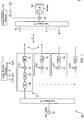
Fig. 1 , a diagram is shown illustrating a multicode aperture transmitter/receiver for a communications system in accordance with an embodiment. InFig. 1 , in an array antenna transmitter system 100 (also referred to as "active array"), asignal 102 is split into low power signals through afeed network 104. The split signal is then transmitted in the form of multiple coded waveforms that are orthogonal to each other through an N number ofRF modules 101 of the arrayantenna transmitter system 100. One of theRF modules 101 may receive a portion of signal 102 (low power signal) viafeed network 104, from where the portion ofsignal 102 may then be directed to eachindividual antenna element 114 via aphase shifter 108, avariable attenuator 110, and acorrelator 112 that codes the portion ofsignal 102 by convolution with a coding waveform fn(t) corresponding to the respectiveindividual antenna element 114. The individual coding waveforms f1(t), f2(t), ......, fn(t) may be supplied by awaveform generator 111 to therespective RF module 101, or alternatively, the coding waveforms may be built-in withinRF modules 101. General techniques for generating random codes are well known in the art as set forth in the technical literature. See for example "Modern Radar" by Raymond S. Berkowitz (John Wiley & Sons, Inc. NY 1965), at . - It will be appreciated that a number of embodiments may exist to split
signal 102 and feed it to themultiple antenna elements 114 of the array antenna transmitter system and are well documented. These may include a parallel feed structure or a corporate feed, a series feed, or a space feed. In this embodiment,feed network 104 is a corporate feed system. Thus,signal 102 may be split into low power signals or portions, and each portion ofsplit signal 102 may be individually coded. Each coded portion ofsignal 102 may then be directed through a high power amplifier (HPA) 113 to be transmitted through the correspondingindividual element 114 of the N-element array antenna transmitter system for a practical distance "R" such that M correlatedreceiver elements 116 are programmed to detect and decode all of the transmitted N coded portions ofsignal 102. The Nindividual elements 114 may be coordinated in phase to achieve high gain and high power as well as controlled direction from coherent summation of radiation from eachindividual element 114. The radiation from all the transmitted coded portions ofsignal 102 is received at the M correlatedreceiver elements 116, where it is coherently integrated and processed. The M correlatedreceiver elements 116 may be a single element, for M equal to one, or may include multiple M correlated receiver elements in the case of a phased array receiver. The coded radiation of each coded portion ofsignal 102 that is received at the M correlatedreceiver elements 116 may be combined through areceive feed network 117. The combined signal may then be decoded atcorrelator 118 for each of the coded waveforms by convolution with the sum of the complex conjugate of the coding waveforms used at the transmitter elements.Correlator 118 may be integrated intoreceiver 120 or it may be separate fromreceiver 120, and it may be either placed beforereceiver 120 or afterreceiver elements 116 and beforefeed network 117. The decoded signals may then be added to give the final received signal. The coding waveforms may be supplied by acorresponding waveform generator 111a at the receiver side or they may be stored in memory atreceiver 120. Consequently, this system operates as a normal communications system and sees the transmitter as a high power, high gain transmitter. - In the case where
receiver 120 is an unmatched or uncorrelated receiver,receiver 120 may detect the transmitted coded signals from the Nindividual elements 114, however, theuncorrelated receiver 120 will not be able to match filter or decode all the coded signals and coherently add them simultaneously because it lacks knowledge of all the codes that were used in generating the transmitted signal. Instead, theuncorrelated receiver 120 observes the codedsplit signal 102 as being very low power signals and will only be able to detect the incoherent sum of the radiated energy from eachindividual element 114, which is very low at any practical distance R because of the broad angular beamwidth of the radiation pattern from each element.Uncorrelated receiver 120, therefore, detects radiation from the Nindividual elements 114 as low power because theuncorrelated receiver 120 sees the antenna as a transmitter with the beam pattern of itsindividual element 114, that is, the pattern of the energy is the far field pattern of an individual array element. - In
Fig. 1 , forindividual elements 114 radiating power "Pe", where Ge is the gain of theindividual element 114, the power density "PD" at a distance "R" for a proportionality constant Kc that accounts for the transmission medium is:
- For "N" elements of the array, where "Pe" is the power per element, the power combines to generate a power density "PD" at a distance "R" as:

- This assumes that the waveforms from the
individual elements 114 are not correlated and so they do not combine coherently. If no coding fn(t) is applied to the portions of thesignal 102, or if all the output portions of thesignal 102 radiated from theelements 114 have the same coded waveforms, then the transmitted radiation from theelements 114 combines coherently for a transmitted power of (N2Pe) and the array antenna gain of (NGe), and the power density at distance "R" is:
- If a correlated
receiver element 116 is provided at distance "R", it will be able to decode all the waveforms from the "N"individual elements 114 and will combine them coherently. In this case, the power density "PD" of correlatedreceiver elements 116 at distance "R" is the same as if all the transmitted coded waveforms were the same or if no coding was applied atelements 114 of the transmitter:
- That is, the power density will be "N2" times higher for a correlated receiver or an array transmitter with the same waveforms for each element than for an uncorrelated receiver and a transmitter with orthogonal coded waveforms for each transmitting element. Consequently, RFI or radiation hazard is reduced by a factor of N2 for a multicode aperture transmitter/receiver while equivalent performance is maintained.
- Referring now to
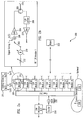
Fig. 2(a) , a diagram is provided illustrating a multicode aperture transmitter/receiver of an active array for a radar system in accordance with an embodiment. Referring also toFig. 2(b) , an exploded view of a T/R RF module 201 ofFig. 2(a) is illustrated according to an embodiment. InFig. 2(a) , an active array may act as a transmitter for which it may also act as a receiver in the case of aradar system 200. Asignal 232 from anexciter 228 is split into low power signals, which are supplied to "N" transmitter/receiver (T/R)RF modules 201 through afeed 212. As shown inFig. 2(b) , each portion of thesplit signal 232 is amplitude adjusted in anattenuator 202 and phase shifted in aphase shifter 210 at eachRF module 201 site to produce a desired radiation beam to illuminate atarget object 222 at a distance "R". For illustration purposes, transmitter/receiver (T/R)switch 203 is shown in the transmit mode of operation. Each portion ofsignal 232 may be convolved with a coding waveform fn(t) at acorrelator 209 for transmission to arespective antenna element 214. Each of the coding waveforms for thedifferent elements 214 may be orthogonal to each other. The coding waveforms may be supplied by asignal generator 211 or may be stored at therespective RF modules 201. General techniques for generating random codes are well known in the art as set forth in the technical literature. During the transmit mode of theradar system 200, T/R switch 203 is connected thereto so that thesplit signal 232 is amplified by transmit driver andfinal amplifiers 204, and routed through acirculator 205 to anindividual element 214. - During the receive mode of
radar system 200,radar system 200 return signals are routed back throughcirculator 205, a receiver protector or T/R limiter 206 and alow noise amplifier 207. The amplified return signal is amplitude adjusted and phase shifted in thesame attenuator 202 andphase shifter 210 respectively. The return signal is then routed to feed 212 and then combined after being decoded with the matched filters for each of the coded waveforms at matchedfilter receiver 216. The decoding may be done inreceiver 216 by convolution of the combined received signal with the complex conjugate of the sum of the coding waveforms, [f1(t)*+ f2(t)*+ ...... +fn(t)*], which are used to code the individual split portions ofsignal 232 at thetransmitter elements 214. Here, the * sign denotes the complex conjugate, i.e., f(t)* is the complex conjugate of f(t). - In one or more embodiments,
control electronics 208 orpower conditioning block 213 may be provided.Control electronics 208 may serve to interfaceRF module 201 to the array controllers, providing beam steering and timing information needed byRF module 201. Power-conditioning block 213 may provide the necessary sequential biases and switching commands for therespective RF module 201 components. - The amplitude weighting (through attenuator 202) in the transmit and receive modes may be used for synthesizing the low sidelobe pattern of the array both during transmit and receive modes. For a pulsed radar, during transmit, the receive side
low noise amplifier 207 output is turned off and during receive, the transmit amplifier input is turned off by T/R switch 203. The radar system dead time may be utilized for changing the phase and attenuator values and for switching channel select T/R switch 203. Other types of radars may include a Continuous Wave (CW) radar with independent Transmitter-Receivers, or an FM-CW radar that may receive while transmitting and that is not pulsed but may use the same coding technique to manage detected power. - Referring to
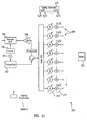
Fig. 2c , a diagram illustrating a multicode aperture transmitter/receiver of a conventional phased array for a radar system is shown in accordance with an embodiment. In this embodiment where a conventional phased array is used instead of an active array,transmitter 252 provides the amplification of aninput signal 251 fromexciter 250 prior to splitting thesignal 251 at feed 254. The portions ofsplit signal 251 are phase shifted throughphase shifters 274. The coded waveforms fn(t) are convolved with the individual portions ofsplit signal 251 atcorrelators 277 prior to transmission through individual transmittingelements 264. Coded waveforms fn(t) may be supplied by acoding generator 272. - The
target object 222 is illuminated by the portions of signal 251 (or multiple low power signals) transmitted through eachindividual element 264, seemingly not correlated to each other, and therefore,target object 222 might not detect that it is being illuminated with microwave radiation. The reflected signals, however, may be received through alow noise amplifier 258, and will be decoded by thereceiver 256 located at the same antenna, and the resultant decoded signals will be added together to create a strong signal. Thus, in the receive mode of theradar system 260, radiation from each individual transmitelement 264 of the array is correlated andreceiver 256 is able to detect and perform coherent addition of all N coded transmissions for all the waveforms in the return signal. - It will be appreciated that as in typical active phased arrays, each individual element 214 (as illustrated in
Fig. 2(a) ) corresponds to anRF module 201, therefore, there may be Nindividual elements 214 that comprise the radar system illuminatingtarget object 222. In typical radar systems, the beam illuminates an object of interest and energy is scattered back to the antenna. The receive elements of the antenna combine the energy received by the individual elements to achieve an increased gain that is equivalent to the physical size of the collection of elements forming an antenna array. Consequently, the coherent addition for a phased array achieves a high gain both for transmit and receive as well as addition of transmitted power from individual low power elements, effectively increasing the power density on the target object of interest and the collected power scattered by the target object. - High power radiation and gain is thus achievable by a correlated receiver, however, radiation is detected as low power at any distance by an uncorrelated receiver or a target object. The phased array, therefore, coherently integrates the transmit/receive patterns and has the effective transmit/receive gain of a full sized antenna enabling the system to effectively act as a high gain transmit/receive antenna.
- According to one or more embodiments for a radar system, a
target object 222 may be illuminated and waveforms returned as described with respect toFigs. 2(a)-2(c) . For a radar system having correlated receivers for each of the receiver individual elements 214 (Figs. 2(a)-2(b) ) or 264 (Fig. 2(c) ), the power detected is:
target object 222 doing the scattering, Kr is a constant depending upon the transmission medium for the radar system, GR is the antenna element gain when in the receive mode resulting in the effective array receive gain of (NGR) and λ is the wavelength of the radiation. The transmit power is (N2Pe) and the effective array transmit gain is (NGe). PD in this case is the power detected by a conventional phased array radar, where no coding was used. For this radar system, the power density PD at distance "R" will be the same as described for the communications system inFigure 1 . If a correlated receiver is present at distance "R" then the power density will be:

- From these equations, it will thus be appreciated that a multicode aperture radar provides equivalent performance while reducing the power density incident at distance "R" by a factor of N2.
- One or more embodiments utilize the gain that is achievable from a phased array antenna to get a factor of N2 improvement in a radar or communications system performance for N individual elements of the array for power density at a density that would be equivalent to that from independent individual elements of the array.
- According to one or more embodiments, power management is achieved as the phased array antenna is configured to look like and have the properties of a full sized antenna, but looks like a collection of small antennas to uncorrelated receivers or target objects. An external receiver or target object sees a very low output of power from the system, making the system less detectable with very low RFI while delivering the necessary power density.
- Although a transmitter/receiver system has been described with respect to a communications system (
Fig. 1 ) as well as radar systems (Figs. 2(a)-2(c) ), there are other applications that would benefit from the configuration of this phased array architecture. For example, in the case of an ultrasound system, the phased array antenna may be replaced by an array of ultrasound transmitters or ultrasound transmitter/receivers, and in the case of an optical or infrared system, the phased array antenna may be replaced by an array of optical or infrared transmitters or optical or infrared transmitter/receivers. - Referring now to
Fig. 3 , a flow diagram illustrating a method for transmitting/receiving signals according to an embodiment is provided. The method ofFig. 3 may be implemented with the communications system shown inFig. 1 where the active array acts as a transmitter with an external cooperative correlated receiver. Also, the method ofFig. 3 may be implemented with the radar systems shown inFigs. 2(a)-2(c) where the phased array acts as a transmitter and a receiver and illuminates anexternal target object 222. Furthermore, the method ofFig. 3 may be implemented in other applications such as an ultrasound system where the phased array antenna may be replaced by an array of ultrasound transmitters or ultrasound transmitter/receivers or an optical or infrared system where the phased array antenna may be replaced by an array of optical or infrared transmitters or optical or infrared transmitter/receivers. - In
block 300, a signal is split into low power signals for feeding into separate elements of an array. As described with respect toFigs. 1 and2(a)-2(c) , the signal is split and each individual portion (low power signal) of the split signal may be coded with waveforms orthogonal to each other and then transmitted through the correspondingindividual element - In
block 301, the portions of the signal transmitted through each individual element of the array are coded with a different code respectively. - In
block 302, each individual element of the array separately transmits the corresponding coded portion of the signal. The coding from the different individual elements is different and orthogonal, that is, an object in space sees the energy from each transmitting element as independent. - In
block 303, it is determined whether the transmitted coded portions of the signal are received by a correlated receiver. If not, inblock 308, an uncorrelated receiver is unable to decode the transmitted coded portions of the signal. The radiation from theindividual elements individual elements Fig. 1 )or seen by the target object 222 (Figs. 2(a)-(c) ), for example, is the incoherent addition of radiation from a collection of low power non-directional antenna elements, which is very low when the loss from propagation to the target object or receiver is taken into account. - In
block 304, if the transmitted coded portions of the signal are received by a correlated receiver, then at least one array element at the receiver side collects the radiation for all the different transmitted coded signals. The collected signal is then fed to the receiver through the feed. In the communications system ofFig. 1 , eachindividual element 116 on an external receiver side collects all the portions ofsignal 102 and sends them to thereceiver 120 where the transmitted signals are decoded and added to form the received signal. In the radar systems ofFig. 2(a)-2(c) , each individual element on a correlated receiver side at the array collects and amplifies all the return coded signals and sends them through the feed to the receiver where they are decoded and added to form the detected return signal. In an optical or infrared system the antenna array may be replaced by optical or infrared laser transmitter/receivers such as laser diode transmitter arrays and receive heterodyne detectors or detector arrays. In an ultrasound system the antenna array may be replaced by ultrasound transmitter arrays/receivers. - In
block 306, all the multiple decoded signals from all the array elements are combined or added. Thus, the array sees the received signals as if they were a high power, high gain transmitter and a high gain receiver, and operates as a conventional high power array system. - According to one or more embodiments, the coded transmitter/receiver system may assist in power management for microwave, optical, ultrasonic or other equipment. In many applications, it is desired to radiate power at levels as low as possible to avoid interference with other equipment and minimize radiation hazards to animate (people or animals, for example, an application would be in avoiding damage to dolphins and whales from Navy sonar testing) or inanimate objects (trigger explosives, damage equipment, etc.). At the same time, radiation of adequate power is necessary so that the equipment functions properly, that is, in the case of a radar system, adequate signal to noise ratio for a given range is desired. In the case of a communications system, adequate power to get acceptable bit error rate is desired.
- Embodiments described above illustrate but do not limit the disclosure. It should also be understood that numerous modifications and variations are possible in accordance with the principles of the present disclosure. Accordingly, the scope of the disclosure is defined only by the following claims.
Claims (11)
- A method of transmitting and receiving signals, the method comprising:splitting (300) a signal into more than one portion for feeding the signal into separate elements of an array of a radar system;coding (301) each portion of the signal for transmission through each separate element of the array by convolving each portion of the signal with a respective different coding waveform (f1, f2,...) ;transmitting (302) each coded portion of the signal through a corresponding separate element of the array;receiving the coded portions of the signal by correlated receiver elements on a receiver side;characterized bydecoding (304) the coded portions of the signal by the correlated receiver elements by convolving the coded portions of the received signal with the sum of the complex conjugates of the coding waveforms (f1*, f2*,...) ; andwherein the sum of the decoded portions of the signal forms a complete received signal,wherein the array further comprises an active antenna array,wherein the receiving the coded portions of the signal by the receiver elements on the receiver side of the radar system further comprises receiving the coded portions of the signal reflected from a target object by separate receiver elements at the active antenna array.
- The method of claim 1, wherein the splitting the signal further comprises using a corporate feed system.
- The method of claim 1, wherein the coding each portion of the signal for transmission through each separate element further comprises coding each portion of the signal respectively with coding waveforms that are orthogonal to each other.
- The method of claim 1, wherein the array further comprises an ultrasound, an optical or an infrared transmitter/receiver array.
- An active antenna array (214) of a radar system (200) for receiving and transmitting a signal comprising:a feed (212) adapted to receive and split the signal into low power signals;a transmitter (212) comprising means configured to code (209) the low power signals by convolving the low power signals with a respective different coding waveform (f1, f2,...);transmitter elements (201) at a transmitter side for transmitting each coded low power signal through a corresponding transmitter element of the array;receiver elements (201) at a receiver side for receiving all the low power signals, wherein the receiver elements at the receiver side in the radar system are part of the active antenna array itself;characterized bya receiver (216) correlated to the transmitter, said receiver comprising means (118) configured to decode the received low power signals with the sum of the complex conjugates of the coding waveforms (f1*, f2*,...), and wherein the sum of the decoded low power signals forms a complete received signal.
- The array of claim 5, further comprising:control electronics (208) and a power conditioning block (213); andan ultrasound, an optical or an infrared receiver/transmitter array.
- The array of claim 5, wherein the elements at the receiver side in the radar system are located externally with an external receiver.
- The array of claim 5, further comprising a waveform generator (211) for supplying the coding waveforms, wherein the coding waveforms are orthogonal to each other.
- The array of claim 5,wherein the means (118) configured to decode are located external to the receiver, wherein the means (118) configured to decode are adapted to decode the low power signals received from the elements at the receiver side and to supply decoded low power signals to the receiver.
- The array of claim 5, further comprising at least one transmit/receive (T/R) module (201), wherein the different codes are built-in within the at least one module.
- The array of claim 5, wherein the receiver further comprises a memory for storing coding waveforms for decoding the low power signals received from the elements at the receiver side.
Applications Claiming Priority (1)
| Application Number | Priority Date | Filing Date | Title |
|---|---|---|---|
| US12/133,959 US8509205B2 (en) | 2008-06-05 | 2008-06-05 | Multicode aperture transmitter/receiver |
Publications (3)
| Publication Number | Publication Date |
|---|---|
| EP2131508A2 EP2131508A2 (en) | 2009-12-09 |
| EP2131508A3 EP2131508A3 (en) | 2010-03-03 |
| EP2131508B1 true EP2131508B1 (en) | 2016-08-10 |
Family
ID=41051158
Family Applications (1)
| Application Number | Title | Priority Date | Filing Date |
|---|---|---|---|
| EP09075091.0A Active EP2131508B1 (en) | 2008-06-05 | 2009-03-02 | Multicode aperture transmitter/receiver |
Country Status (3)
| Country | Link |
|---|---|
| US (1) | US8509205B2 (en) |
| EP (1) | EP2131508B1 (en) |
| JP (1) | JP5595676B2 (en) |
Families Citing this family (24)
| Publication number | Priority date | Publication date | Assignee | Title |
|---|---|---|---|---|
| US8958408B1 (en) | 2008-06-05 | 2015-02-17 | The Boeing Company | Coded aperture scanning |
| US20120268315A1 (en) * | 2009-10-21 | 2012-10-25 | Anatol Zymunt Tirkel | Wide area detection of insects using reflected microwaves |
| US8934663B2 (en) * | 2009-10-29 | 2015-01-13 | Optimark, L.L.C. | Digital watermarking |
| US8879995B2 (en) * | 2009-12-23 | 2014-11-04 | Viconics Electronics Inc. | Wireless power transmission using phased array antennae |
| ES2461998T3 (en) * | 2010-04-08 | 2014-05-22 | Elbit Systems Ew And Sigint - Elisra Ltd. | Electronic countermeasures system |
| JP5886207B2 (en) | 2010-12-10 | 2016-03-16 | パナソニック インテレクチュアル プロパティ コーポレーション オブアメリカPanasonic Intellectual Property Corporation of America | Signal generation method and signal generation apparatus |
| US9182485B1 (en) * | 2011-05-24 | 2015-11-10 | Garmin International, Inc. | Transmit/receive module for electronically steered weather radar |
| CN102292870B (en) * | 2011-06-16 | 2013-09-11 | 华为技术有限公司 | Phased-array antenna aligning method and device and phased-array antenna |
| US9787463B2 (en) * | 2011-10-14 | 2017-10-10 | Maxlinear, Inc. | Method and system for server-side message handling in a low-power wide area network |
| US9451469B2 (en) * | 2012-07-23 | 2016-09-20 | Intel Corporation | Apparatus and method for tunneled GPM |
| US10656257B2 (en) | 2013-04-29 | 2020-05-19 | Greina Technologies, Inc. | Personal radar |
| US9891312B2 (en) * | 2013-04-29 | 2018-02-13 | Greina Technologies, Inc. | Personal radar |
| GB201312027D0 (en) * | 2013-07-04 | 2013-08-21 | Norwegian Univ Sci & Tech Ntnu | RF MIMO transmitter |
| US9874626B2 (en) * | 2014-12-15 | 2018-01-23 | The Boeing Company | Multicode transmitter |
| WO2016126908A1 (en) * | 2015-02-04 | 2016-08-11 | Artsys360 Ltd. | Multimodal radar system |
| US10324166B2 (en) * | 2015-09-28 | 2019-06-18 | Rockwell Collins, Inc. | Affordable combined pulsed/FMCW radar AESA |
| WO2017099813A1 (en) * | 2015-12-11 | 2017-06-15 | Gm Global Technology Operations, Llc | Aperture coding for transmit and receive beamforming |
| US20180011190A1 (en) * | 2016-07-05 | 2018-01-11 | Navico Holding As | High Ping Rate Sonar |
| US10567014B2 (en) | 2016-10-31 | 2020-02-18 | The Johns Hopkins University | High power transmission using multi-tone signals |
| US10401475B2 (en) * | 2016-12-06 | 2019-09-03 | GM Global Technology Operations LLC | Multiple modulation element radar waveform generation |
| US10484095B2 (en) | 2017-06-15 | 2019-11-19 | The Aerospace Corporation | Communications relay satellite with a single-axis gimbal |
| GB2569811A (en) * | 2017-12-27 | 2019-07-03 | Creo Medical Ltd | Electrosurgical apparatus |
| US11047956B2 (en) * | 2018-06-14 | 2021-06-29 | Semiconductor Components Industries, Llc | Reconfigurable MIMO radar |
| CN112485780A (en) * | 2020-11-05 | 2021-03-12 | 上海大学 | Radar-measuring material three-dimensional material level sensor system with phased array antenna |
Citations (1)
| Publication number | Priority date | Publication date | Assignee | Title |
|---|---|---|---|---|
| EP1918734A1 (en) * | 2006-11-04 | 2008-05-07 | Roke Manor Research Limited | A multiple input multiple output RADAR system |
Family Cites Families (33)
| Publication number | Priority date | Publication date | Assignee | Title |
|---|---|---|---|---|
| JPH01134284A (en) * | 1987-11-19 | 1989-05-26 | Mitsubishi Electric Corp | Proximity fuse |
| US4974187A (en) * | 1989-08-02 | 1990-11-27 | Aware, Inc. | Modular digital signal processing system |
| JPH0777362B2 (en) * | 1990-08-28 | 1995-08-16 | クラリオン株式会社 | Spread spectrum communication device |
| US5276455A (en) * | 1991-05-24 | 1994-01-04 | The Boeing Company | Packaging architecture for phased arrays |
| DE69425542T2 (en) * | 1993-10-15 | 2001-03-29 | Hitachi Ltd | Logical circuit with error detection function, method for managing equipment and fault-tolerant system for its application |
| JPH08195703A (en) * | 1995-01-17 | 1996-07-30 | Toshiba Corp | Radio communication equipment |
| US5793798A (en) * | 1995-12-18 | 1998-08-11 | Ail Systems, Inc. | Virtual beam system |
| US5961463A (en) * | 1998-08-24 | 1999-10-05 | General Electric Company | Nonlinear imaging using orthogonal transmit and receive codes |
| AU3308400A (en) * | 1999-03-18 | 2000-10-04 | British Broadcasting Corporation, The | Watermarking |
| US6351499B1 (en) * | 1999-12-15 | 2002-02-26 | Iospan Wireless, Inc. | Method and wireless systems using multiple antennas and adaptive control for maximizing a communication parameter |
| US6375618B1 (en) * | 2000-01-31 | 2002-04-23 | General Electric Company | Enhanced tissue-generated harmonic imaging using coded excitation |
| EP1295150A2 (en) * | 2000-05-05 | 2003-03-26 | Greenwich Technologies | Remote sensing using rayleigh signaling |
| EP1364479B1 (en) * | 2000-09-01 | 2010-04-28 | Broadcom Corporation | Satellite receiver and corresponding method |
| US6665825B1 (en) * | 2000-11-06 | 2003-12-16 | Agere Systems Inc. | Cellular CDMA transmission system |
| US6487433B2 (en) * | 2001-01-08 | 2002-11-26 | General Electric Company | Method and apparatus using golay-coded excitation for echocardiology |
| GB2399998B (en) * | 2001-02-01 | 2005-04-13 | Fujitsu Ltd | Communications systems |
| US7197282B2 (en) * | 2001-07-26 | 2007-03-27 | Ericsson Inc. | Mobile station loop-back signal processing |
| US7466743B2 (en) * | 2001-09-12 | 2008-12-16 | Infineon Technologies Ag | CDMA wireless systems |
| JP2003152607A (en) * | 2001-11-08 | 2003-05-23 | Ntt Docomo Inc | Communication method, communication system, transmitter and receiver |
| EP1775873A3 (en) * | 2002-01-04 | 2012-12-26 | Nokia Corporation | Reception of signals in a high rate transmission diversity system |
| US20030135374A1 (en) * | 2002-01-16 | 2003-07-17 | Hardwick John C. | Speech synthesizer |
| DE60320546T2 (en) * | 2002-03-28 | 2008-11-13 | Koninklijke Philips Electronics N.V. | LABELING OF TIME RANGE WITH WATERMARK FOR MULTIMEDIA SIGNALS |
| US20040087294A1 (en) * | 2002-11-04 | 2004-05-06 | Tia Mobile, Inc. | Phases array communication system utilizing variable frequency oscillator and delay line network for phase shift compensation |
| US7421276B2 (en) * | 2003-04-09 | 2008-09-02 | Nortel Networks Limited | Method, apparatus and system of configuring a wireless device based on location |
| US7079869B2 (en) * | 2003-02-12 | 2006-07-18 | Lucent Technologies Inc. | Communication system transmitter or receiver module having integrated radio frequency circuitry directly coupled to antenna element |
| US6954173B2 (en) * | 2003-07-02 | 2005-10-11 | Raytheon Company | Techniques for measurement of deformation of electronically scanned antenna array structures |
| US20080225375A1 (en) * | 2004-09-07 | 2008-09-18 | Raytheon Company | Optically frequency generated scanned active array |
| FR2880748B1 (en) * | 2005-01-12 | 2007-02-16 | Commissariat Energie Atomique | MULTI ANTENNA COMMUNICATION SYSTEM |
| US8279985B2 (en) * | 2005-02-22 | 2012-10-02 | Adaptix, Inc. | Intelligent demodulation systems and methods in an OFDMA multicell network |
| US20060210279A1 (en) * | 2005-02-28 | 2006-09-21 | Hillis W D | Optical Antenna Assembly |
| US7277046B2 (en) * | 2005-07-08 | 2007-10-02 | Raytheon Company | Single transmit multi-receiver modulation radar, multi-modulation receiver and method |
| US8072943B2 (en) * | 2005-12-09 | 2011-12-06 | Samsung Electronics Co., Ltd. | Wireless communication system and methodology for communicating via multiple information streams |
| US8706165B2 (en) * | 2006-01-25 | 2014-04-22 | Telefonaktiebolaget Lm Ericsson (Publ) | Method and apparatus for reducing combiner loss in a multi-sector, omni-base station |
-
2008
- 2008-06-05 US US12/133,959 patent/US8509205B2/en active Active
-
2009
- 2009-03-02 EP EP09075091.0A patent/EP2131508B1/en active Active
- 2009-05-29 JP JP2009130956A patent/JP5595676B2/en active Active
Patent Citations (1)
| Publication number | Priority date | Publication date | Assignee | Title |
|---|---|---|---|---|
| EP1918734A1 (en) * | 2006-11-04 | 2008-05-07 | Roke Manor Research Limited | A multiple input multiple output RADAR system |
Non-Patent Citations (3)
| Title |
|---|
| DANIEL J RABIDEAU: "Adaptive MIMO radar waveforms", RADAR CONFERENCE, 2008. RADAR '08. IEEE, IEEE, PISCATAWAY, NJ, USA, 26 May 2008 (2008-05-26), pages 1 - 6, XP031376313, ISBN: 978-1-4244-1538-0 * |
| DANIEL J RABIDEAU: "Nonadaptive MIMO radar techniques for reducing clutter", RADAR CONFERENCE, 2008. RADAR '08. IEEE, IEEE, PISCATAWAY, NJ, USA, 26 May 2008 (2008-05-26), pages 1 - 6, XP031376277, ISBN: 978-1-4244-1538-0 * |
| JAMESON BERGIN ET AL: "MIMO Phased-Array for SMTI Radar", AEROSPACE CONFERENCE, 2008 IEEE, IEEE, PISCATAWAY, NJ, USA, 1 March 2008 (2008-03-01), pages 1 - 7, XP031256286, ISBN: 978-1-4244-1487-1 * |
Also Published As
| Publication number | Publication date |
|---|---|
| JP5595676B2 (en) | 2014-09-24 |
| EP2131508A2 (en) | 2009-12-09 |
| US20090303126A1 (en) | 2009-12-10 |
| EP2131508A3 (en) | 2010-03-03 |
| JP2009296580A (en) | 2009-12-17 |
| US8509205B2 (en) | 2013-08-13 |
Similar Documents
| Publication | Publication Date | Title |
|---|---|---|
| EP2131508B1 (en) | Multicode aperture transmitter/receiver | |
| EP2669700B1 (en) | Electronic counter measure system | |
| US8559823B2 (en) | Multi-aperture three-dimensional beamforming | |
| US7737879B2 (en) | Split aperture array for increased short range target coverage | |
| US8958408B1 (en) | Coded aperture scanning | |
| US7423578B1 (en) | Split aperture array for increased short range target coverage | |
| US8405541B2 (en) | Multi-range radar system | |
| US20200249344A1 (en) | Radar sensor apparatus for vehicle, object detecting method, and antenna apparatus therefor | |
| US20080143587A1 (en) | Multiple input multiple output RADAR system | |
| EP2541679A1 (en) | Wideband beam forming device, wideband beam steering device and corresponding methods | |
| US9885777B2 (en) | Detection of stealth vehicles using VHF radar | |
| Butt et al. | Hybrid phased-MIMO radar: A novel approach with optimal performance under electronic countermeasures | |
| EP3306745B1 (en) | Sensor device | |
| US20020021240A1 (en) | Remote sensing using rayleigh signaling | |
| US9915728B2 (en) | Sub-diffraction limit resolution radar arrays | |
| US9874626B2 (en) | Multicode transmitter | |
| Anajemba et al. | Efficient switched digital beamforming radar system based on SIMO/MIMO receiver | |
| Blunt et al. | Multi-waveform STAP | |
| Mahmoud et al. | Bi-directional phased-MIMO antenna array | |
| Graham et al. | Radar architecture using MIMO transmit subarrays | |
| Ismail et al. | Design and Analysis of Planar Phased MIMO Antenna for Radar Applications. | |
| IL204908A (en) | Electronic counter measure system |
Legal Events
| Date | Code | Title | Description |
|---|---|---|---|
| PUAI | Public reference made under article 153(3) epc to a published international application that has entered the european phase |
Free format text: ORIGINAL CODE: 0009012 |
|
| AK | Designated contracting states |
Kind code of ref document: A2 Designated state(s): AT BE BG CH CY CZ DE DK EE ES FI FR GB GR HR HU IE IS IT LI LT LU LV MC MK MT NL NO PL PT RO SE SI SK TR |
|
| AX | Request for extension of the european patent |
Extension state: AL BA RS |
|
| PUAL | Search report despatched |
Free format text: ORIGINAL CODE: 0009013 |
|
| AK | Designated contracting states |
Kind code of ref document: A3 Designated state(s): AT BE BG CH CY CZ DE DK EE ES FI FR GB GR HR HU IE IS IT LI LT LU LV MC MK MT NL NO PL PT RO SE SI SK TR |
|
| AX | Request for extension of the european patent |
Extension state: AL BA RS |
|
| 17P | Request for examination filed |
Effective date: 20100727 |
|
| 17Q | First examination report despatched |
Effective date: 20100820 |
|
| AKX | Designation fees paid |
Designated state(s): AT BE BG CH CY CZ DE DK EE ES FI FR GB GR HR HU IE IS IT LI LT LU LV MC MK MT NL NO PL PT RO SE SI SK TR |
|
| GRAP | Despatch of communication of intention to grant a patent |
Free format text: ORIGINAL CODE: EPIDOSNIGR1 |
|
| RIC1 | Information provided on ipc code assigned before grant |
Ipc: G01S 13/02 20060101ALI20160411BHEP Ipc: H04B 7/06 20060101AFI20160411BHEP Ipc: G01S 13/28 20060101ALI20160411BHEP Ipc: H04B 7/08 20060101ALN20160411BHEP |
|
| RIC1 | Information provided on ipc code assigned before grant |
Ipc: H04B 7/08 20060101ALN20160420BHEP Ipc: H04B 7/06 20060101AFI20160420BHEP Ipc: G01S 13/02 20060101ALI20160420BHEP Ipc: G01S 13/28 20060101ALI20160420BHEP |
|
| INTG | Intention to grant announced |
Effective date: 20160504 |
|
| GRAR | Information related to intention to grant a patent recorded |
Free format text: ORIGINAL CODE: EPIDOSNIGR71 |
|
| GRAS | Grant fee paid |
Free format text: ORIGINAL CODE: EPIDOSNIGR3 |
|
| GRAA | (expected) grant |
Free format text: ORIGINAL CODE: 0009210 |
|
| AK | Designated contracting states |
Kind code of ref document: B1 Designated state(s): AT BE BG CH CY CZ DE DK EE ES FI FR GB GR HR HU IE IS IT LI LT LU LV MC MK MT NL NO PL PT RO SE SI SK TR |
|
| INTG | Intention to grant announced |
Effective date: 20160706 |
|
| REG | Reference to a national code |
Ref country code: GB Ref legal event code: FG4D |
|
| RIC1 | Information provided on ipc code assigned before grant |
Ipc: G01S 13/02 20060101ALI20160701BHEP Ipc: H04B 7/06 20060101AFI20160701BHEP Ipc: G01S 13/28 20060101ALI20160701BHEP Ipc: H04B 7/08 20060101ALN20160701BHEP |
|
| REG | Reference to a national code |
Ref country code: CH Ref legal event code: EP Ref country code: AT Ref legal event code: REF Ref document number: 819872 Country of ref document: AT Kind code of ref document: T Effective date: 20160815 |
|
| REG | Reference to a national code |
Ref country code: IE Ref legal event code: FG4D |
|
| REG | Reference to a national code |
Ref country code: DE Ref legal event code: R096 Ref document number: 602009040177 Country of ref document: DE |
|
| REG | Reference to a national code |
Ref country code: LT Ref legal event code: MG4D |
|
| REG | Reference to a national code |
Ref country code: NL Ref legal event code: MP Effective date: 20160810 |
|
| REG | Reference to a national code |
Ref country code: AT Ref legal event code: MK05 Ref document number: 819872 Country of ref document: AT Kind code of ref document: T Effective date: 20160810 |
|
| PG25 | Lapsed in a contracting state [announced via postgrant information from national office to epo] |
Ref country code: FI Free format text: LAPSE BECAUSE OF FAILURE TO SUBMIT A TRANSLATION OF THE DESCRIPTION OR TO PAY THE FEE WITHIN THE PRESCRIBED TIME-LIMIT Effective date: 20160810 Ref country code: NL Free format text: LAPSE BECAUSE OF FAILURE TO SUBMIT A TRANSLATION OF THE DESCRIPTION OR TO PAY THE FEE WITHIN THE PRESCRIBED TIME-LIMIT Effective date: 20160810 Ref country code: HR Free format text: LAPSE BECAUSE OF FAILURE TO SUBMIT A TRANSLATION OF THE DESCRIPTION OR TO PAY THE FEE WITHIN THE PRESCRIBED TIME-LIMIT Effective date: 20160810 Ref country code: LT Free format text: LAPSE BECAUSE OF FAILURE TO SUBMIT A TRANSLATION OF THE DESCRIPTION OR TO PAY THE FEE WITHIN THE PRESCRIBED TIME-LIMIT Effective date: 20160810 Ref country code: NO Free format text: LAPSE BECAUSE OF FAILURE TO SUBMIT A TRANSLATION OF THE DESCRIPTION OR TO PAY THE FEE WITHIN THE PRESCRIBED TIME-LIMIT Effective date: 20161110 Ref country code: IS Free format text: LAPSE BECAUSE OF FAILURE TO SUBMIT A TRANSLATION OF THE DESCRIPTION OR TO PAY THE FEE WITHIN THE PRESCRIBED TIME-LIMIT Effective date: 20161210 Ref country code: IT Free format text: LAPSE BECAUSE OF FAILURE TO SUBMIT A TRANSLATION OF THE DESCRIPTION OR TO PAY THE FEE WITHIN THE PRESCRIBED TIME-LIMIT Effective date: 20160810 |
|
| PG25 | Lapsed in a contracting state [announced via postgrant information from national office to epo] |
Ref country code: PT Free format text: LAPSE BECAUSE OF FAILURE TO SUBMIT A TRANSLATION OF THE DESCRIPTION OR TO PAY THE FEE WITHIN THE PRESCRIBED TIME-LIMIT Effective date: 20161212 Ref country code: ES Free format text: LAPSE BECAUSE OF FAILURE TO SUBMIT A TRANSLATION OF THE DESCRIPTION OR TO PAY THE FEE WITHIN THE PRESCRIBED TIME-LIMIT Effective date: 20160810 Ref country code: GR Free format text: LAPSE BECAUSE OF FAILURE TO SUBMIT A TRANSLATION OF THE DESCRIPTION OR TO PAY THE FEE WITHIN THE PRESCRIBED TIME-LIMIT Effective date: 20161111 Ref country code: PL Free format text: LAPSE BECAUSE OF FAILURE TO SUBMIT A TRANSLATION OF THE DESCRIPTION OR TO PAY THE FEE WITHIN THE PRESCRIBED TIME-LIMIT Effective date: 20160810 Ref country code: LV Free format text: LAPSE BECAUSE OF FAILURE TO SUBMIT A TRANSLATION OF THE DESCRIPTION OR TO PAY THE FEE WITHIN THE PRESCRIBED TIME-LIMIT Effective date: 20160810 Ref country code: SE Free format text: LAPSE BECAUSE OF FAILURE TO SUBMIT A TRANSLATION OF THE DESCRIPTION OR TO PAY THE FEE WITHIN THE PRESCRIBED TIME-LIMIT Effective date: 20160810 Ref country code: AT Free format text: LAPSE BECAUSE OF FAILURE TO SUBMIT A TRANSLATION OF THE DESCRIPTION OR TO PAY THE FEE WITHIN THE PRESCRIBED TIME-LIMIT Effective date: 20160810 |
|
| REG | Reference to a national code |
Ref country code: FR Ref legal event code: PLFP Year of fee payment: 9 |
|
| PG25 | Lapsed in a contracting state [announced via postgrant information from national office to epo] |
Ref country code: RO Free format text: LAPSE BECAUSE OF FAILURE TO SUBMIT A TRANSLATION OF THE DESCRIPTION OR TO PAY THE FEE WITHIN THE PRESCRIBED TIME-LIMIT Effective date: 20160810 Ref country code: EE Free format text: LAPSE BECAUSE OF FAILURE TO SUBMIT A TRANSLATION OF THE DESCRIPTION OR TO PAY THE FEE WITHIN THE PRESCRIBED TIME-LIMIT Effective date: 20160810 |
|
| REG | Reference to a national code |
Ref country code: DE Ref legal event code: R097 Ref document number: 602009040177 Country of ref document: DE |
|
| PG25 | Lapsed in a contracting state [announced via postgrant information from national office to epo] |
Ref country code: BG Free format text: LAPSE BECAUSE OF FAILURE TO SUBMIT A TRANSLATION OF THE DESCRIPTION OR TO PAY THE FEE WITHIN THE PRESCRIBED TIME-LIMIT Effective date: 20161110 Ref country code: BE Free format text: LAPSE BECAUSE OF FAILURE TO SUBMIT A TRANSLATION OF THE DESCRIPTION OR TO PAY THE FEE WITHIN THE PRESCRIBED TIME-LIMIT Effective date: 20160810 Ref country code: DK Free format text: LAPSE BECAUSE OF FAILURE TO SUBMIT A TRANSLATION OF THE DESCRIPTION OR TO PAY THE FEE WITHIN THE PRESCRIBED TIME-LIMIT Effective date: 20160810 Ref country code: SK Free format text: LAPSE BECAUSE OF FAILURE TO SUBMIT A TRANSLATION OF THE DESCRIPTION OR TO PAY THE FEE WITHIN THE PRESCRIBED TIME-LIMIT Effective date: 20160810 Ref country code: CZ Free format text: LAPSE BECAUSE OF FAILURE TO SUBMIT A TRANSLATION OF THE DESCRIPTION OR TO PAY THE FEE WITHIN THE PRESCRIBED TIME-LIMIT Effective date: 20160810 |
|
| PLBE | No opposition filed within time limit |
Free format text: ORIGINAL CODE: 0009261 |
|
| STAA | Information on the status of an ep patent application or granted ep patent |
Free format text: STATUS: NO OPPOSITION FILED WITHIN TIME LIMIT |
|
| 26N | No opposition filed |
Effective date: 20170511 |
|
| PG25 | Lapsed in a contracting state [announced via postgrant information from national office to epo] |
Ref country code: SI Free format text: LAPSE BECAUSE OF FAILURE TO SUBMIT A TRANSLATION OF THE DESCRIPTION OR TO PAY THE FEE WITHIN THE PRESCRIBED TIME-LIMIT Effective date: 20160810 |
|
| REG | Reference to a national code |
Ref country code: CH Ref legal event code: PL |
|
| PG25 | Lapsed in a contracting state [announced via postgrant information from national office to epo] |
Ref country code: MC Free format text: LAPSE BECAUSE OF FAILURE TO SUBMIT A TRANSLATION OF THE DESCRIPTION OR TO PAY THE FEE WITHIN THE PRESCRIBED TIME-LIMIT Effective date: 20160810 |
|
| REG | Reference to a national code |
Ref country code: IE Ref legal event code: MM4A |
|
| PG25 | Lapsed in a contracting state [announced via postgrant information from national office to epo] |
Ref country code: LU Free format text: LAPSE BECAUSE OF NON-PAYMENT OF DUE FEES Effective date: 20170302 |
|
| PG25 | Lapsed in a contracting state [announced via postgrant information from national office to epo] |
Ref country code: IE Free format text: LAPSE BECAUSE OF NON-PAYMENT OF DUE FEES Effective date: 20170302 Ref country code: CH Free format text: LAPSE BECAUSE OF NON-PAYMENT OF DUE FEES Effective date: 20170331 Ref country code: LI Free format text: LAPSE BECAUSE OF NON-PAYMENT OF DUE FEES Effective date: 20170331 |
|
| REG | Reference to a national code |
Ref country code: FR Ref legal event code: PLFP Year of fee payment: 10 |
|
| PG25 | Lapsed in a contracting state [announced via postgrant information from national office to epo] |
Ref country code: MT Free format text: LAPSE BECAUSE OF NON-PAYMENT OF DUE FEES Effective date: 20170302 |
|
| PG25 | Lapsed in a contracting state [announced via postgrant information from national office to epo] |
Ref country code: HU Free format text: LAPSE BECAUSE OF FAILURE TO SUBMIT A TRANSLATION OF THE DESCRIPTION OR TO PAY THE FEE WITHIN THE PRESCRIBED TIME-LIMIT; INVALID AB INITIO Effective date: 20090302 |
|
| PG25 | Lapsed in a contracting state [announced via postgrant information from national office to epo] |
Ref country code: CY Free format text: LAPSE BECAUSE OF NON-PAYMENT OF DUE FEES Effective date: 20160810 |
|
| PG25 | Lapsed in a contracting state [announced via postgrant information from national office to epo] |
Ref country code: MK Free format text: LAPSE BECAUSE OF FAILURE TO SUBMIT A TRANSLATION OF THE DESCRIPTION OR TO PAY THE FEE WITHIN THE PRESCRIBED TIME-LIMIT Effective date: 20160810 |
|
| PG25 | Lapsed in a contracting state [announced via postgrant information from national office to epo] |
Ref country code: TR Free format text: LAPSE BECAUSE OF FAILURE TO SUBMIT A TRANSLATION OF THE DESCRIPTION OR TO PAY THE FEE WITHIN THE PRESCRIBED TIME-LIMIT Effective date: 20160810 |
|
| PGFP | Annual fee paid to national office [announced via postgrant information from national office to epo] |
Ref country code: FR Payment date: 20230328 Year of fee payment: 15 |
|
| PGFP | Annual fee paid to national office [announced via postgrant information from national office to epo] |
Ref country code: GB Payment date: 20230327 Year of fee payment: 15 Ref country code: DE Payment date: 20230329 Year of fee payment: 15 |
|
| P01 | Opt-out of the competence of the unified patent court (upc) registered |
Effective date: 20230516 |