EP2190234A1 - System, method and network device for covering a plurality of areas by one cell - Google Patents
System, method and network device for covering a plurality of areas by one cell Download PDFInfo
- Publication number
- EP2190234A1 EP2190234A1 EP08783872A EP08783872A EP2190234A1 EP 2190234 A1 EP2190234 A1 EP 2190234A1 EP 08783872 A EP08783872 A EP 08783872A EP 08783872 A EP08783872 A EP 08783872A EP 2190234 A1 EP2190234 A1 EP 2190234A1
- Authority
- EP
- European Patent Office
- Prior art keywords
- data channel
- signals
- bbu
- downlink
- uplink signals
- Prior art date
- Legal status (The legal status is an assumption and is not a legal conclusion. Google has not performed a legal analysis and makes no representation as to the accuracy of the status listed.)
- Granted
Links
- 238000000034 method Methods 0.000 title claims abstract description 28
- 238000012545 processing Methods 0.000 claims description 26
- 238000010586 diagram Methods 0.000 description 5
- 230000003247 decreasing effect Effects 0.000 description 3
- 230000006855 networking Effects 0.000 description 3
- 238000004891 communication Methods 0.000 description 2
- 238000010276 construction Methods 0.000 description 2
- 238000012986 modification Methods 0.000 description 2
- 230000004048 modification Effects 0.000 description 2
- 238000006243 chemical reaction Methods 0.000 description 1
- 238000013507 mapping Methods 0.000 description 1
- 238000004148 unit process Methods 0.000 description 1
- 239000002699 waste material Substances 0.000 description 1
Images


Classifications
-
- H—ELECTRICITY
- H04—ELECTRIC COMMUNICATION TECHNIQUE
- H04B—TRANSMISSION
- H04B7/00—Radio transmission systems, i.e. using radiation field
- H04B7/14—Relay systems
- H04B7/15—Active relay systems
- H04B7/155—Ground-based stations
- H04B7/15507—Relay station based processing for cell extension or control of coverage area
-
- H—ELECTRICITY
- H04—ELECTRIC COMMUNICATION TECHNIQUE
- H04B—TRANSMISSION
- H04B7/00—Radio transmission systems, i.e. using radiation field
- H04B7/24—Radio transmission systems, i.e. using radiation field for communication between two or more posts
- H04B7/26—Radio transmission systems, i.e. using radiation field for communication between two or more posts at least one of which is mobile
- H04B7/2603—Arrangements for wireless physical layer control
- H04B7/2606—Arrangements for base station coverage control, e.g. by using relays in tunnels
-
- H—ELECTRICITY
- H04—ELECTRIC COMMUNICATION TECHNIQUE
- H04W—WIRELESS COMMUNICATION NETWORKS
- H04W72/00—Local resource management
- H04W72/04—Wireless resource allocation
-
- H—ELECTRICITY
- H04—ELECTRIC COMMUNICATION TECHNIQUE
- H04W—WIRELESS COMMUNICATION NETWORKS
- H04W72/00—Local resource management
- H04W72/04—Wireless resource allocation
- H04W72/044—Wireless resource allocation based on the type of the allocated resource
- H04W72/0473—Wireless resource allocation based on the type of the allocated resource the resource being transmission power
-
- H—ELECTRICITY
- H04—ELECTRIC COMMUNICATION TECHNIQUE
- H04W—WIRELESS COMMUNICATION NETWORKS
- H04W88/00—Devices specially adapted for wireless communication networks, e.g. terminals, base stations or access point devices
- H04W88/08—Access point devices
-
- H—ELECTRICITY
- H04—ELECTRIC COMMUNICATION TECHNIQUE
- H04W—WIRELESS COMMUNICATION NETWORKS
- H04W16/00—Network planning, e.g. coverage or traffic planning tools; Network deployment, e.g. resource partitioning or cells structures
- H04W16/24—Cell structures
- H04W16/26—Cell enhancers or enhancement, e.g. for tunnels, building shadow
Definitions
- the present invention relates to network communication, and in particular, to a system, a method, a Base Station, and a Radio Network Controller (RNC) for one cell to cover multiple areas.
- RNC Radio Network Controller
- one cell may cover multiple areas. Given below are two solutions to one cell covering multiple areas.
- Solution 1 A Base Station and a repeater enable one cell to cover multiple areas, as shown in FIG. 1 and FIG. 2 .
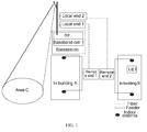
- FIG. 1 three areas, namely, area C, building A, and building B belong to the same cell.
- a local end 1 and a remote end 1 constitute a repeater, and a local end 2 and a remote end 2 constitute another repeater. Therefore, one Base Station and two repeaters accomplish coverage for three areas (A, B, and C) in a cell. Areas A, B, and C belong to one cell, and the cell corresponds to one Radio Frequency (RF) module in the Base Station.
- the remote end 1 includes an RF module
- the remote end 2 includes an RF module. Therefore, three RF modules are required for one cell to cover multiple areas in FIG. 1 .
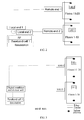
- floors 1-10 and floors 11-20 belong to the same cell.
- a local end 1 and a remote end 1 constitute a repeater, and the repeater covers higher floors 11-20.
- a local end 2 and a remote end 2 constitute another repeater, and this repeater covers lower floors 1-10. Therefore, one Base Station and two repeaters accomplish coverage for two areas (higher-floor area, and lower-floor area) in a cell.
- the higher-floor area and the lower-floor area belong to one cell, and the cell corresponds to one RF module in the Base Station.
- the remote end 1 includes an RF module
- the remote end 2 includes an RF module. Therefore, three RF modules are required for one cell to cover multiple areas in FIG. 2 .
- Solution 2 A Baseband Unit (BBU) and a Remote Radio Unit (RRU) enable one cell to cover multiple areas, as shown in FIG. 3 .
- BBU Baseband Unit
- RRU Remote Radio Unit
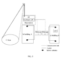
- lower floors 1-10 and higher floors 11-20 belong to the same cell.
- RRU 1 covers higher floors 11-20
- RRU 2 covers lower floors 1-10
- RRU 1 and RRU 2 are connected with the BBU in the Base Station through a Digital Combiner and Divider unit. Therefore, two remote RF modules and a digital combiner and divider unit accomplish coverage for both the higher-floor area and the lower-floor area in a cell.
- the embodiments of the present invention provide a system and a method for one cell to cover multiple areas, and a network device to increase the uplink capacity and the downlink capacity, reduce the networking cost, and facilitate the implementation of cell splitting.
- the system for one cell to cover multiple areas includes:
- each RF group corresponds to an area in a cell
- each data channel corresponds to an RF group.
- the BBU can receive the uplink signals in the areas corresponding to different RF groups through multiple data channels; when the uplink signals in different areas are sent to the BBU through different data channels, the interference caused by the uplink signals between different areas is avoided, and the uplink capacity is improved; in the downlink direction, the BBU sends downlink signals to the UEs in different areas through different data channels; when the downlink signals in different areas are sent through different data channels, the interference caused by the downlink signals between different areas is avoided, and the downlink capacity is improved.
- a system for one cell to cover multiple areas in an embodiment of the present invention includes multiple RF groups and at least one BBU.
- the BBU is connected with multiple RF groups through multiple data channels. That is, one BBU corresponds to multiple data channels, and is connected with an RF group through a data channel.
- the data channel is configured to exchange information between the RF group and the BBU.
- the data channel may include an antenna interface of the BBU, or include a digital-analog conversion module between the RF group and the BBU. This embodiment of the present invention does not restrict the style of the data channel.
- one RF group corresponds to an area in a cell. That is, one RF group covers an area in a cell.
- the area in the embodiments of the present invention is specific to an RF group, namely, the scope covered by an RF group is regarded as an area.
- area C in FIG. 1 serves as an area, and corresponds to an RF group
- building A and building B serve as another area and correspond to an RF group. That is, one RF group covers area C, and the other RF group covers building A and building B.
- the quantity of the RF groups depends on the quantity of data channels. That is, the quantity of the RF groups may keep consistent with the quantity of the data channels. For example, if a BBU corresponds to n data channels, the quantity of the RF groups may be n. In this case, an RF group may correspond to a data channel. In the embodiments of the present invention, the quantity of the RF groups may also be less than the quantity of data channels. For example, if a BBU corresponds to 5 data channels, the quantity of the RF groups may be an integer between 1 and 5. In this case, some data channels may correspond to no RF group.
- the RF group is configured to send uplink signals to the BBU through a data channel, and send downlink signals from the data channel.
- the uplink signals received by the RF group are sent by the UE in coverage area of the RF group.
- the RF group After receiving the uplink signals from the UE, the RF group sends the uplink signals to the BBU through the corresponding data channel.
- the RF group After receiving the downlink signals on the data channel, the RF group sends the downlink signals to the UE in coverage area of the RF group.
- the BBU is configured to receive uplink signals and send downlink signals through multiple data channels.
- the BBU may receive uplink signals of the UEs in different areas in a cell from multiple data channels.
- the BBU may send downlink signals through the corresponding data channel. For example, when the downlink signal is sent to a UE in an area, the BBU may send the downlink signal through a data channel corresponding to an RF group that covers the UE. In this way, other RF groups do not perform transmitting operations for this downlink signal, thus avoiding decrease of the downlink capacity mentioned in the second solution in the prior art.
- the BBU may search each data channel respectively. After an uplink signal is found on the data channel, the BBU performs subsequent processing for the uplink signal found on the data channel.
- the signal processing may be finger demodulation, channel estimation, maximum ratio combination, or decoding, or any combination thereof. This embodiment of the present invention does not restrict the process of processing the uplink signals. If the BBU finds no uplink signal on a data channel, the signals such as noise on the data channel are not involved in the subsequent signal processing, thus avoiding interference caused by noise to the uplink signals.
- the BBU may send the downlink signals through the corresponding data channel according to the control of the RNC, or send the downlink signals through the corresponding data channel according to its own control.
- the process of control on sending the downlink signals through the corresponding data channel may be implemented by selecting the data channel corresponding to the downlink signals intelligently according to the information about the received uplink signals. For example, in the process of receiving the uplink signals through the data channel, the BBU may determine the data channel that bears the received uplink signals.
- the BBU may send the identifier information of the data channel that bears the uplink signals to the RNC, and the RNC may determine the data channel corresponding to downlink signals according to the identifier information of the data channel that bears the received uplink signals and according to the information in the downlink signals. Therefore, the BBU may send the downlink signals according to the data channel determined by the RNC.
- the BBU may record the identifier information of the data channel that bears the uplink signals. In this way, the BBU may determine the data channel corresponding to the downlink signals according to the recorded identifier information of the data channel that bears the uplink signals and according to the information in the downlink signals, and send the downlink signals through the determined data channel.
- the identifier information of the data channel that bears the uplink signals may include the identifier information of the uplink signals and the identifier information of the data channel.
- the BBU includes: multiple Searchers, a signal processing unit, and a downlink sending module.
- Each Searcher corresponds to a data channel, namely, a Searcher corresponds to an RF group.
- the Searcher searches the corresponding data channel to check whether any uplink signals exist on the data channel.
- the Searcher sends the uplink signal to the signal processing unit. If the Searcher finds no uplink signal on the corresponding data channel, the signals such as noise on the data channel are not sent to the signal processing unit, thus avoiding interference caused by noise to the uplink signals.
- the Searcher may output the the identifier information of the data channel that bears the uplink signals.
- the signal processing unit is configured to process the uplink signals transmitted by the Searcher.
- the processing may be finger demodulation, signal estimation, maximum ratio combination, or decoding, or any combination thereof.
- the signal processing unit includes but is not limited to: a finger demodulator, a channel estimating module, a Maximum Ratio Combination (MRC) module, or a decoder, or any combination thereof.
- the processing performed by the signal processing unit for the uplink signals may be set according to the requirements in the actual network.
- the process of the Base Station processing uplink signals in the prior art is applicable. This embodiment of the present invention does not restrict how the signal processing unit processes the uplink signals.
- the downlink sending module is configured to send the downlink signals through the corresponding data channel according to the received control information.
- the control information received by the downlink sending module may be transmitted from other modules in the BBU, or from the RNC.
- the BBU further includes a storing module and a downlink control module.
- the storing module is configured to record identifier information of the data channel that bears the uplink signals according to the uplink signals found by the Searcher. For example, the storing module receives and stores the identifier information of the data channel that bears the uplink signals output by the Searcher.
- the identifier information of the data channel that bears the uplink signals may include the mapping relation between the uplink signal and the data channel.
- the downlink control module is configured to determine the data channel corresponding to downlink signals to be sent according to the information in the downlink signals and identifier information of the data channel that bears the uplink signals stored in the storing module, and output control information to the downlink sending module.
- the storing module and the downlink control module may also be set in the RNC.
- the RF group in this embodiment is appropriate only if it can receive downlink signals and send the downlink signals to the UE, and can receive uplink signals of the UE and send the uplink signals to the BBU.
- the RF group may be any type of receiving and sending apparatuses in the prior art.
- the RF group may be a combination of a remote RF module, an RF module, and a combiner, or a combination of multiple remote RF modules and a remote RF module hub (RHUB), or a combination of a repeater, a coupler and an RF module, or a combination of a trunk amplifier, a coupler, and an RF module.
- This embodiment of the present invention does not restrict the style of the RF group.
- FIG. 4 shows a system for one cell to cover multiple areas in an embodiment of the present invention.
- the system for one cell to cover multiple areas includes n (n ⁇ 1) RF groups and a BBU.
- FIG. 4 illustrates only three types of RF groups.
- RF group 1 RGroup-1
- an RRU and an RF module are connected with the combiner.
- the uplink signals are sent to the BBU over the corresponding data channel through an RRU/RF and a combiner; and the downlink signals are sent to the UE in the area covered by RGroup-1 over the corresponding data channel through a combiner, an RRU, and an RF module.
- Two RRUs in RF group 2 (RGroup-2) are connected with one RHUB. Nevertheless, RGroup-2 may include more RRUs.
- the uplink signals are sent to the BBU over the corresponding data channel through an RRU and an RHUB, and the downlink signals are sent to the UE in the area covered by RGroup-2 over the corresponding data channel through an RHUB and an RRU.
- a repeater in RF group n (RGroup-n) is connected with the RF module through a coupler.
- the repeater in RGroup-n may also be a trunk amplifier, the uplink signals are sent to the BBU over the corresponding data channel through a repeater, a coupler, and an RF, or sent to the BBU over the corresponding data channel through an RF directly, and the downlink signals are sent to the UE in the area covered by RGroup-n over the corresponding data channel through an RF, or sent to the UE in the area covered by RGroup-n over the corresponding data channel through an RF, a coupler, and a repeater.
- Other implementation modes of the RF group are not enumerated here any further.
- the BBU in FIG. 4 includes n (n ⁇ 1) Searchers, a Finger Demodulator, a Channel Estimator module, an MRC module, and a Decoder.
- the Finger Demodulator, the Channel Estimator module, the MRC module, and Decoder make up a signal processing unit.
- the signal processing unit may also be set according to the network conditions. Other modes of the signal processing unit are not elaborated here any further.
- FIG. 4 does not show the Downlink Sending module in the BBU, the Storing module or the Downlink Control module in the system.
- Each Searcher searches for the corresponding RF group (RGroup) as an antenna of Cell 1(BBU1).
- each Searcher searches for the finger of the corresponding RGroup. Searching for a finger is equivalent to searching for an uplink signal. If no finger of the RGroup is found, the data such as noise in the corresponding data channel is not involved in the finger demodulation and the subsequent signal processing. That is, such data (noise) does not cause any interference to the uplink signals of the current UE, starting from the Searcher. That improves the uplink capacity of the cell.
- the Searcher may output the information about the RGroup that send the uplink signals of the UE. That is, the Searcher may output the identifier information of the data channel that bears the uplink signals.
- the BBU or RNC may determine the data channel corresponding to the downlink signals according to the search results of the uplink signals. For example, the BBU or RNC may determine the data channel corresponding to the downlink signals according to the Searcher output which reveals the RGroup that sends the uplink signals. Therefore, the BBU may transmit the downlink signals to the RGroup in the area that covers the UE through the corresponding data channel, without the need of transmitting downlink signals to all RGroups in the cell.
- any UE in the same cell may receive the downlink signals of all UEs in the cell.
- the BBU may make downlink signals be transmitted in only the area that covers the UE according to the RF group selected intelligently.
- the UE receives only the downlink signals of all UEs in the area covered by the RGroup of this UE rather than receives the downlink signals of all UEs in the area covered by other RGroup in this cell, thus reducing interference between downlink signals, saving the downlink transmitting power, increasing the downlink capacity, and decreasing the operation cost.
- the system in this embodiment can select an area intelligently for transmitting downlink signals. Therefore, the system in this embodiment is known as a Smart Multi-RRU/RF One Cell (SMROC) system.
- SMROC Smart Multi-RRU/RF One Cell
- FIG. 5 and FIG. 6 the system provided in an embodiment of the present invention is elaborated below with reference to specific application scenarios.
- the application scenario of FIG. 5 and FIG. 6 is the same as the application scenario of FIG. 1 and FIG. 2 .
- FIG. 5 three areas, namely, area C, building A, and building B belong to the same cell.
- RGroup-1 covers the area of building A
- RGroup-2 covers the area of building B
- the RF module in the Base Station covers area C.
- the RF module in the Base Station, RGroup-l, and RGroup-2 are connected with the BBU in the Base Station.
- area A, area B, and area C may be one cell, and the three areas in the cell may share the baseband resources in the Base Station.
- Three areas A, B, and C may exchange signals with the BBU through three data channels.
- the UE in any of areas A, B, and C never receives the downlink signals of the UE in other areas, thus avoiding the downlink signal interference between area A, area B and area C, and increasing the downlink capacity.
- area A, area B, and area C send uplink signals to the BBU through different data channels, thus avoiding the uplink signal interference between area A, area B, and area C, and increasing the uplink capacity.
- upgrade, and expansion if three areas in a cell need to be split into three cells, that purpose may be accomplished without cable adjustment, thus avoiding high costs and difficulty of cell splitting caused by re-cabling. If three areas in a cell need to be split into three cells, and the RGroup-1 and RGroup-2 include an RRU, no RF module needs to be added for RGroup-1 and RGroup-2 in the Base Station.
- floors 1-10 and floors 11-20 belong to the same cell.
- RGroup-1 covers the higher-floor area
- RGroup-2 covers the lower-floor area. Therefore, two areas (higher-floor area and lower-floor area) in a cell are covered through two RF groups.
- the higher-floor area and the lower-floor area may be one cell, and two areas in the cell may share the baseband resources in the Base Station.
- the higher-floor area and the lower-floor area may exchange signals with the BBU through two data channels. In this way, the UE in neither the higher-floor area nor the lower-floor area receives the downlink signals of the UE in other areas, thus avoiding the downlink signal interference between the higher-floor area and the lower-floor area and increasing the downlink capacity.
- the higher-floor area and the lower-floor area send uplink signals to the BBU through different data channels, thus avoiding the uplink signal interference between the higher-floor area and the lower-floor area, and increasing the uplink capacity.
- only two RF modules need to be set for the RF group in this embodiment.
- an RF module is saved in the system in this embodiment, and the networking cost is reduced.
- upgrade, and expansion if two areas in a cell need to be split into two cells, that purpose may be accomplished without cable adjustment, thus avoiding high costs and difficulty of cell splitting caused by re-cabling. If two areas in a cell need to be split into two cells, and the RGroup-1 and RGroup-2 include an RRU, no RF module needs to be added for RGroup-1 and RGroup-2 in the Base Station.
- the Base Station and the RNC in this embodiment are the same as those described in the foregoing system embodiment, and are not repeated here any further.
- a method for one cell to cover multiple areas in an embodiment of the present invention is described below.
- the method involves multiple RF groups and at least one BBU.
- One BBU corresponds to multiple data channels
- a BBU is connected with an RF group through a data channel
- an RF group covers an area in a cell.
- the area, the quantity of RF groups, and the RF group implementation mode are the same as those described in the foregoing system embodiment.
- the method in this embodiment involves a process of transmitting uplink signals and downlink signals.
- the RF group receives the uplink signals from the UE, and sends the uplink signals to the BBU through the corresponding data channel.
- the BBU searches multiple data channels for uplink signals, the BBU processes the found uplink signals. If the BBU finds no uplink signal on a data channel, the BBU does not need to process the signals such as noise on the data channel, thus avoiding interference caused by noise to the uplink signals.
- the BBU may record the identifier information of the data channel that bears the uplink signal, and may send the identifier information of the data channel to the RNC.
- the signal processing and the recording of the identifier information of the data channel that bears the uplink signal are the same as the counterpart processing in the system embodiment described above.
- the BBU uses the data channel corresponding to the downlink signals to send downlink signals to the corresponding RF group, and the RF group sends the downlink signals to the UE in its coverage area after receiving the downlink signals on the data channel.
- the BBU may send downlink signals of a UE through a data channel. In some application scenarios, however, the BBU may send the downlink signals of a UE through multiple data channels.
- the BBU may send the downlink signals through the corresponding data channel according to the control of the RNC, or send the downlink signals through the corresponding data channel according to its own control.
- the process of control on sending the downlink signals through the corresponding data channel may be implemented by selecting the data channel corresponding to the downlink signals intelligently according to the information about the received uplink signals.
- the process of determining the data channel corresponding to the downlink signals according to the uplink signals is the same as the counterpart process in the system embodiment described above.
- the BBU may receive uplink signals in the areas corresponding to different RF groups through multiple data channels. Therefore, when the uplink signals in different areas are sent to the BBU through different data channels, the uplink signal interference between different areas is avoided, and the uplink capacity is increased. Moreover, if the BBU finds no uplink signal from a data channel, the BBU does not perform subsequent processing for the signals such as noise on the data channel, and the interference caused by the signals such as noise to the uplink signals is avoided. In the downlink direction, the BBU or RNC may select the data channel corresponding to the downlink signals intelligently according to the uplink signals.
- the BBU may send the downlink signals to the UEs in different areas through different data channels.
- the downlink signals in different areas are sent through different data channels, the downlink signal interference between different areas is avoided, and the downlink capacity is increased.
- the area corresponding to an RF group has no downlink signal ready for sending but the area corresponding to other RF groups has downlink signals ready for sending, the situation that all RF groups need power transmitting is avoided, and the downlink capacity is further increased.
- no re-cabling is required, thus reducing the cost of cell splitting and facilitating the implementation of cell splitting.
- the system in this embodiment does need to add an RF module at the Base Station, thus reducing the networking cost and facilitating the cell splitting, namely, facilitating the upgrade and expansion in network evolution.
Abstract
Description
- The present invention relates to network communication, and in particular, to a system, a method, a Base Station, and a Radio Network Controller (RNC) for one cell to cover multiple areas.
- In the current communication system, one cell may cover multiple areas. Given below are two solutions to one cell covering multiple areas.
- Solution 1: A Base Station and a repeater enable one cell to cover multiple areas, as shown in
FIG. 1 andFIG. 2 . - In
FIG. 1 , three areas, namely, area C, building A, and building B belong to the same cell. Alocal end 1 and aremote end 1 constitute a repeater, and alocal end 2 and aremote end 2 constitute another repeater. Therefore, one Base Station and two repeaters accomplish coverage for three areas (A, B, and C) in a cell. Areas A, B, and C belong to one cell, and the cell corresponds to one Radio Frequency (RF) module in the Base Station. Theremote end 1 includes an RF module, and theremote end 2 includes an RF module. Therefore, three RF modules are required for one cell to cover multiple areas inFIG. 1 . - In
FIG. 2 , floors 1-10 and floors 11-20 belong to the same cell. Alocal end 1 and aremote end 1 constitute a repeater, and the repeater covers higher floors 11-20. Alocal end 2 and aremote end 2 constitute another repeater, and this repeater covers lower floors 1-10. Therefore, one Base Station and two repeaters accomplish coverage for two areas (higher-floor area, and lower-floor area) in a cell. The higher-floor area and the lower-floor area belong to one cell, and the cell corresponds to one RF module in the Base Station. Theremote end 1 includes an RF module, and theremote end 2 includes an RF module. Therefore, three RF modules are required for one cell to cover multiple areas inFIG. 2 . - Solution 2: A Baseband Unit (BBU) and a Remote Radio Unit (RRU) enable one cell to cover multiple areas, as shown in
FIG. 3 . - In
FIG. 3 , lower floors 1-10 and higher floors 11-20 belong to the same cell. RRU 1 covers higher floors 11-20, RRU 2 covers lower floors 1-10, and RRU 1 and RRU 2 are connected with the BBU in the Base Station through a Digital Combiner and Divider unit. Therefore, two remote RF modules and a digital combiner and divider unit accomplish coverage for both the higher-floor area and the lower-floor area in a cell. - In the process of implementing the present invention, the inventor finds at least the following two problems in
solution 1 in the prior art: - Problem 1: The system capacity is decreased. The repeater raises the noise floor of the Base Station. The rise of the noise floor interferes with all users in the same cell, and increases interference to neighboring cells. Moreover, in the uplink direction, the RF module in the Base Station receives signals of User Equipment (UE) in multiple coverage areas simultaneously, and the uplink signals lead to interference between different areas; in the downlink direction, the UE in a coverage area receives the downlink signals sent to the UE in other coverage areas while receiving the downlink signals sent to this UE, and the downlink signals lead to interference between different areas. Such factors affect the system capacity.
- Problem 2: If multiple areas in a cell need to be split into cells, additional RF modules need to be set in the Base Station, and re-cabling is required for the RF modules and the local end in the Base Station. Therefore, the cell splitting is costly and difficult.
- In the process of developing the present invention, the inventor finds at least the following two problems in
solution 2 in the prior art: - Problem 1: Interference exists between users in a cell. For example, in the uplink direction, the signals of
UE 1 in the higher-floor area are gathered by the digital combiner to the BBU, and lead to interference toUE 2 in the lower-floor area. - Problem 2: The downlink capacity is decreased. For example, in the downlink direction, if only
UE 2 in the lower-floor area is in a conversation, the transmitting power ofRRU 2 is 1 w. However, due to principles of the digital combiner and divider unit, the transmitting power ofRRU 1 is 1 w too. Such power is a waste toRRU 1, and is equivalent to decrease of the downlink capacity. Besides, if UE 1 and UE 2 in different areas talk with each other, according to the digital combiner and divider unit, RRU 1 send downlink signals to both UE 1 and UE 2 simultaneously. UE 1 receives not only the required signals, but also the downlink signals sent by RRU 1 to UE 2, which are interference to UE 1 and further decrease the downlink capacity. - The embodiments of the present invention provide a system and a method for one cell to cover multiple areas, and a network device to increase the uplink capacity and the downlink capacity, reduce the networking cost, and facilitate the implementation of cell splitting.
- The system for one cell to cover multiple areas includes:
- multiple RF groups, configured to receive uplink signals sent by a UE in the corresponding area, send the uplink signals to a BBU through the corresponding data channel, receive downlink signals through the corresponding data channel, and send the downlink signals to the UE in the corresponding area, where each RF group corresponds to an area in a cell and corresponds to a data channel; and
- at least one BBU, connected with the multiple RF groups through multiple data channels, and configured to receive the uplink signals through the data channel and send the downlink signals to the corresponding RF group through the corresponding data channel.
- In the method for one cell to cover multiple areas in an embodiment of the present invention, each RF group corresponds to an area in a cell, and each data channel corresponds to an RF group. The method includes:
- receiving, by an RF group, uplink signals in the corresponding area, and sending the uplink signals to a BBU through the data channel corresponding to the RF group;
- receiving, by the BBU, the uplink signals through the data channel, and sending downlink signals to the corresponding RF group through the data channel corresponding to the downlink signals; and
- receiving, by the RF group, the downlink signals through the data channel, and sending the downlink signals to the area corresponding to the RF group.
- A base Station provided in an embodiment of the present invention includes:
- at least one BBU, each BBU is connected with multiple RF groups through multiple data channels and each data channel corresponds to an RF group, configured to receive uplink signals of a UE sent from different RF groups through each data channel, and send downlink signals to the corresponding RF group through the data channel corresponding to the downlink signals
- An RNC provided in an embodiment of the present invention includes:
- a storing module, configured to record identifier information of a data channel that bears uplink signals according to the uplink signals found by a BBU in a Base Station; and
- a downlink control module, configured to determine the data channel corresponding to downlink signals according to information in the downlink signals to be sent and according to the recorded identifier information of the data channel that bears the uplink signals, and output control information on the data channel corresponding to the downlink signals to the BBU of the Base Station.
- The foregoing technical solution reveals that: In the embodiments of the present invention, multiple data channels of the BBU are applied; each data channel is connected with an RF group so that the RF group can exchange signals with the BBU through the corresponding data channel. Therefore, in the uplink direction, the BBU can receive the uplink signals in the areas corresponding to different RF groups through multiple data channels; when the uplink signals in different areas are sent to the BBU through different data channels, the interference caused by the uplink signals between different areas is avoided, and the uplink capacity is improved; in the downlink direction, the BBU sends downlink signals to the UEs in different areas through different data channels; when the downlink signals in different areas are sent through different data channels, the interference caused by the downlink signals between different areas is avoided, and the downlink capacity is improved. Moreover, in the case that downlink signals do not need to be sent in the area corresponding to one RF group but need to be sent in the areas corresponding to other RF groups, power transmitting is not required in all RF groups, and the downlink capacity is further improved. When multiple areas in a cell are split into multiple cells, no re-cabling is required, thus reducing the cost of cell splitting and facilitating the implementation of cell splitting.
-
-
FIG. 1 is the first schematic diagram of one cell covering multiple areas through "Base Station + repeater" in the prior art; -
FIG. 2 is the second schematic diagram of one cell covering multiple areas through "Base Station + repeater" in the prior art; -
FIG. 3 is a schematic diagram of one cell covering multiple areas through "BBU + RRU" in the prior art; -
FIG. 4 shows a system for one cell to cover multiple areas in an embodiment of the present invention; -
FIG. 5 is the first schematic diagram of an application scenario of a system for one cell to cover multiple areas in an embodiment of the present invention; and -
FIG. 6 is the second schematic diagram of an application scenario of a system for one cell to cover multiple areas in an embodiment of the present invention. - A system for one cell to cover multiple areas in an embodiment of the present invention includes multiple RF groups and at least one BBU. The BBU is connected with multiple RF groups through multiple data channels. That is, one BBU corresponds to multiple data channels, and is connected with an RF group through a data channel. The data channel is configured to exchange information between the RF group and the BBU. The data channel may include an antenna interface of the BBU, or include a digital-analog conversion module between the RF group and the BBU. This embodiment of the present invention does not restrict the style of the data channel.
- In the embodiments of the present invention, one RF group corresponds to an area in a cell. That is, one RF group covers an area in a cell. The area in the embodiments of the present invention is specific to an RF group, namely, the scope covered by an RF group is regarded as an area. For example, area C in
FIG. 1 serves as an area, and corresponds to an RF group, and building A and building B serve as another area and correspond to an RF group. That is, one RF group covers area C, and the other RF group covers building A and building B. - In the embodiments of the present invention, the quantity of the RF groups depends on the quantity of data channels. That is, the quantity of the RF groups may keep consistent with the quantity of the data channels. For example, if a BBU corresponds to n data channels, the quantity of the RF groups may be n. In this case, an RF group may correspond to a data channel. In the embodiments of the present invention, the quantity of the RF groups may also be less than the quantity of data channels. For example, if a BBU corresponds to 5 data channels, the quantity of the RF groups may be an integer between 1 and 5. In this case, some data channels may correspond to no RF group.
- The RF group is configured to send uplink signals to the BBU through a data channel, and send downlink signals from the data channel. The uplink signals received by the RF group are sent by the UE in coverage area of the RF group. After receiving the uplink signals from the UE, the RF group sends the uplink signals to the BBU through the corresponding data channel. After receiving the downlink signals on the data channel, the RF group sends the downlink signals to the UE in coverage area of the RF group.
- The BBU is configured to receive uplink signals and send downlink signals through multiple data channels. The BBU may receive uplink signals of the UEs in different areas in a cell from multiple data channels. The BBU may send downlink signals through the corresponding data channel. For example, when the downlink signal is sent to a UE in an area, the BBU may send the downlink signal through a data channel corresponding to an RF group that covers the UE. In this way, other RF groups do not perform transmitting operations for this downlink signal, thus avoiding decrease of the downlink capacity mentioned in the second solution in the prior art.
- When the BBU receives the uplink signal, the BBU may search each data channel respectively. After an uplink signal is found on the data channel, the BBU performs subsequent processing for the uplink signal found on the data channel. The signal processing may be finger demodulation, channel estimation, maximum ratio combination, or decoding, or any combination thereof. This embodiment of the present invention does not restrict the process of processing the uplink signals. If the BBU finds no uplink signal on a data channel, the signals such as noise on the data channel are not involved in the subsequent signal processing, thus avoiding interference caused by noise to the uplink signals.
- When sending the downlink signals, the BBU may send the downlink signals through the corresponding data channel according to the control of the RNC, or send the downlink signals through the corresponding data channel according to its own control. The process of control on sending the downlink signals through the corresponding data channel may be implemented by selecting the data channel corresponding to the downlink signals intelligently according to the information about the received uplink signals. For example, in the process of receiving the uplink signals through the data channel, the BBU may determine the data channel that bears the received uplink signals. The BBU may send the identifier information of the data channel that bears the uplink signals to the RNC, and the RNC may determine the data channel corresponding to downlink signals according to the identifier information of the data channel that bears the received uplink signals and according to the information in the downlink signals. Therefore, the BBU may send the downlink signals according to the data channel determined by the RNC. The BBU may record the identifier information of the data channel that bears the uplink signals. In this way, the BBU may determine the data channel corresponding to the downlink signals according to the recorded identifier information of the data channel that bears the uplink signals and according to the information in the downlink signals, and send the downlink signals through the determined data channel. The identifier information of the data channel that bears the uplink signals may include the identifier information of the uplink signals and the identifier information of the data channel.
- In this embodiment, the BBU includes: multiple Searchers, a signal processing unit, and a downlink sending module.
- Each Searcher corresponds to a data channel, namely, a Searcher corresponds to an RF group. The Searcher searches the corresponding data channel to check whether any uplink signals exist on the data channel. When finding any uplink signal on the data channel, the Searcher sends the uplink signal to the signal processing unit. If the Searcher finds no uplink signal on the corresponding data channel, the signals such as noise on the data channel are not sent to the signal processing unit, thus avoiding interference caused by noise to the uplink signals. After searching out any uplink signal on the data channel, the Searcher may output the the identifier information of the data channel that bears the uplink signals.
- The signal processing unit is configured to process the uplink signals transmitted by the Searcher. The processing may be finger demodulation, signal estimation, maximum ratio combination, or decoding, or any combination thereof. Accordingly, the signal processing unit includes but is not limited to: a finger demodulator, a channel estimating module, a Maximum Ratio Combination (MRC) module, or a decoder, or any combination thereof. The processing performed by the signal processing unit for the uplink signals may be set according to the requirements in the actual network. The process of the Base Station processing uplink signals in the prior art is applicable. This embodiment of the present invention does not restrict how the signal processing unit processes the uplink signals.
- The downlink sending module is configured to send the downlink signals through the corresponding data channel according to the received control information. The control information received by the downlink sending module may be transmitted from other modules in the BBU, or from the RNC.
- If the control information received by the downlink sending module is transmitted from other modules in the BBU, the BBU further includes a storing module and a downlink control module.
- The storing module is configured to record identifier information of the data channel that bears the uplink signals according to the uplink signals found by the Searcher. For example, the storing module receives and stores the identifier information of the data channel that bears the uplink signals output by the Searcher. The identifier information of the data channel that bears the uplink signals may include the mapping relation between the uplink signal and the data channel.
- The downlink control module is configured to determine the data channel corresponding to downlink signals to be sent according to the information in the downlink signals and identifier information of the data channel that bears the uplink signals stored in the storing module, and output control information to the downlink sending module.
- The storing module and the downlink control module may also be set in the RNC.
- The RF group in this embodiment is appropriate only if it can receive downlink signals and send the downlink signals to the UE, and can receive uplink signals of the UE and send the uplink signals to the BBU. The RF group may be any type of receiving and sending apparatuses in the prior art. For example, the RF group may be a combination of a remote RF module, an RF module, and a combiner, or a combination of multiple remote RF modules and a remote RF module hub (RHUB), or a combination of a repeater, a coupler and an RF module, or a combination of a trunk amplifier, a coupler, and an RF module. This embodiment of the present invention does not restrict the style of the RF group.
- A system for one cell to cover multiple areas in an embodiment of the present invention is described below with reference to an accompanying drawing.
-
FIG. 4 shows a system for one cell to cover multiple areas in an embodiment of the present invention. InFIG. 4 , the system for one cell to cover multiple areas includes n (n≥ 1) RF groups and a BBU. -
FIG. 4 illustrates only three types of RF groups. In RF group 1 (RGroup-1), an RRU and an RF module are connected with the combiner. The uplink signals are sent to the BBU over the corresponding data channel through an RRU/RF and a combiner; and the downlink signals are sent to the UE in the area covered by RGroup-1 over the corresponding data channel through a combiner, an RRU, and an RF module. Two RRUs in RF group 2 (RGroup-2) are connected with one RHUB. Nevertheless, RGroup-2 may include more RRUs. The uplink signals are sent to the BBU over the corresponding data channel through an RRU and an RHUB, and the downlink signals are sent to the UE in the area covered by RGroup-2 over the corresponding data channel through an RHUB and an RRU. A repeater in RF group n (RGroup-n) is connected with the RF module through a coupler. The repeater in RGroup-n may also be a trunk amplifier, the uplink signals are sent to the BBU over the corresponding data channel through a repeater, a coupler, and an RF, or sent to the BBU over the corresponding data channel through an RF directly, and the downlink signals are sent to the UE in the area covered by RGroup-n over the corresponding data channel through an RF, or sent to the UE in the area covered by RGroup-n over the corresponding data channel through an RF, a coupler, and a repeater. Other implementation modes of the RF group are not enumerated here any further. - The BBU in
FIG. 4 includes n (n≥ 1) Searchers, a Finger Demodulator, a Channel Estimator module, an MRC module, and a Decoder. The Finger Demodulator, the Channel Estimator module, the MRC module, and Decoder make up a signal processing unit. The signal processing unit may also be set according to the network conditions. Other modes of the signal processing unit are not elaborated here any further.FIG. 4 does not show the Downlink Sending module in the BBU, the Storing module or the Downlink Control module in the system. - Each Searcher searches for the corresponding RF group (RGroup) as an antenna of Cell 1(BBU1).
- In the uplink direction, each Searcher searches for the finger of the corresponding RGroup. Searching for a finger is equivalent to searching for an uplink signal. If no finger of the RGroup is found, the data such as noise in the corresponding data channel is not involved in the finger demodulation and the subsequent signal processing. That is, such data (noise) does not cause any interference to the uplink signals of the current UE, starting from the Searcher. That improves the uplink capacity of the cell. According to the search result of the Searcher, the Searcher may output the information about the RGroup that send the uplink signals of the UE. That is, the Searcher may output the identifier information of the data channel that bears the uplink signals.
- In the downlink direction, the BBU or RNC may determine the data channel corresponding to the downlink signals according to the search results of the uplink signals. For example, the BBU or RNC may determine the data channel corresponding to the downlink signals according to the Searcher output which reveals the RGroup that sends the uplink signals. Therefore, the BBU may transmit the downlink signals to the RGroup in the area that covers the UE through the corresponding data channel, without the need of transmitting downlink signals to all RGroups in the cell.
- In the prior art, any UE in the same cell may receive the downlink signals of all UEs in the cell. In this embodiment, although multiple RGroups belong to the same cell, the BBU may make downlink signals be transmitted in only the area that covers the UE according to the RF group selected intelligently. In this way, the UE receives only the downlink signals of all UEs in the area covered by the RGroup of this UE rather than receives the downlink signals of all UEs in the area covered by other RGroup in this cell, thus reducing interference between downlink signals, saving the downlink transmitting power, increasing the downlink capacity, and decreasing the operation cost.
- The system in this embodiment can select an area intelligently for transmitting downlink signals. Therefore, the system in this embodiment is known as a Smart Multi-RRU/RF One Cell (SMROC) system.
- As shown in
FIG. 5 andFIG. 6 , the system provided in an embodiment of the present invention is elaborated below with reference to specific application scenarios. The application scenario ofFIG. 5 andFIG. 6 is the same as the application scenario ofFIG. 1 andFIG. 2 . - In
FIG. 5 , three areas, namely, area C, building A, and building B belong to the same cell. RGroup-1 covers the area of building A, RGroup-2 covers the area of building B, and the RF module in the Base Station covers area C. The RF module in the Base Station, RGroup-l, and RGroup-2 are connected with the BBU in the Base Station. At the beginning of network construction, area A, area B, and area C may be one cell, and the three areas in the cell may share the baseband resources in the Base Station. Three areas A, B, and C may exchange signals with the BBU through three data channels. In this way, the UE in any of areas A, B, and C never receives the downlink signals of the UE in other areas, thus avoiding the downlink signal interference between area A, area B and area C, and increasing the downlink capacity. In the uplink direction, area A, area B, and area C send uplink signals to the BBU through different data channels, thus avoiding the uplink signal interference between area A, area B, and area C, and increasing the uplink capacity. Moreover, in the subsequent network evolution, upgrade, and expansion, if three areas in a cell need to be split into three cells, that purpose may be accomplished without cable adjustment, thus avoiding high costs and difficulty of cell splitting caused by re-cabling. If three areas in a cell need to be split into three cells, and the RGroup-1 and RGroup-2 include an RRU, no RF module needs to be added for RGroup-1 and RGroup-2 in the Base Station. - In
FIG. 6 , floors 1-10 and floors 11-20 belong to the same cell. RGroup-1 covers the higher-floor area, and RGroup-2 covers the lower-floor area. Therefore, two areas (higher-floor area and lower-floor area) in a cell are covered through two RF groups. At the beginning of network construction, the higher-floor area and the lower-floor area may be one cell, and two areas in the cell may share the baseband resources in the Base Station. The higher-floor area and the lower-floor area may exchange signals with the BBU through two data channels. In this way, the UE in neither the higher-floor area nor the lower-floor area receives the downlink signals of the UE in other areas, thus avoiding the downlink signal interference between the higher-floor area and the lower-floor area and increasing the downlink capacity. In the uplink direction, the higher-floor area and the lower-floor area send uplink signals to the BBU through different data channels, thus avoiding the uplink signal interference between the higher-floor area and the lower-floor area, and increasing the uplink capacity. Moreover, in the application scenario inFIG. 6 , only two RF modules need to be set for the RF group in this embodiment. As shown inFIG. 6 in comparison withFIG. 2 , an RF module is saved in the system in this embodiment, and the networking cost is reduced. Moreover, in the subsequent network evolution, upgrade, and expansion, if two areas in a cell need to be split into two cells, that purpose may be accomplished without cable adjustment, thus avoiding high costs and difficulty of cell splitting caused by re-cabling. If two areas in a cell need to be split into two cells, and the RGroup-1 and RGroup-2 include an RRU, no RF module needs to be added for RGroup-1 and RGroup-2 in the Base Station. - The Base Station and the RNC in this embodiment are the same as those described in the foregoing system embodiment, and are not repeated here any further.
- A method for one cell to cover multiple areas in an embodiment of the present invention is described below.
- The method involves multiple RF groups and at least one BBU. One BBU corresponds to multiple data channels, a BBU is connected with an RF group through a data channel, and an RF group covers an area in a cell. The area, the quantity of RF groups, and the RF group implementation mode are the same as those described in the foregoing system embodiment.
- The method in this embodiment involves a process of transmitting uplink signals and downlink signals.
- In the uplink direction, the RF group receives the uplink signals from the UE, and sends the uplink signals to the BBU through the corresponding data channel. When the BBU searches multiple data channels for uplink signals, the BBU processes the found uplink signals. If the BBU finds no uplink signal on a data channel, the BBU does not need to process the signals such as noise on the data channel, thus avoiding interference caused by noise to the uplink signals. After finding an uplink signal, the BBU may record the identifier information of the data channel that bears the uplink signal, and may send the identifier information of the data channel to the RNC. The signal processing and the recording of the identifier information of the data channel that bears the uplink signal are the same as the counterpart processing in the system embodiment described above.
- In the downlink direction, the BBU uses the data channel corresponding to the downlink signals to send downlink signals to the corresponding RF group, and the RF group sends the downlink signals to the UE in its coverage area after receiving the downlink signals on the data channel. The BBU may send downlink signals of a UE through a data channel. In some application scenarios, however, the BBU may send the downlink signals of a UE through multiple data channels. When sending the downlink signals, the BBU may send the downlink signals through the corresponding data channel according to the control of the RNC, or send the downlink signals through the corresponding data channel according to its own control. The process of control on sending the downlink signals through the corresponding data channel may be implemented by selecting the data channel corresponding to the downlink signals intelligently according to the information about the received uplink signals. The process of determining the data channel corresponding to the downlink signals according to the uplink signals is the same as the counterpart process in the system embodiment described above.
- In the embodiments of the present invention, in the uplink direction, the BBU may receive uplink signals in the areas corresponding to different RF groups through multiple data channels. Therefore, when the uplink signals in different areas are sent to the BBU through different data channels, the uplink signal interference between different areas is avoided, and the uplink capacity is increased. Moreover, if the BBU finds no uplink signal from a data channel, the BBU does not perform subsequent processing for the signals such as noise on the data channel, and the interference caused by the signals such as noise to the uplink signals is avoided. In the downlink direction, the BBU or RNC may select the data channel corresponding to the downlink signals intelligently according to the uplink signals. In this way, the BBU may send the downlink signals to the UEs in different areas through different data channels. When the downlink signals in different areas are sent through different data channels, the downlink signal interference between different areas is avoided, and the downlink capacity is increased. Moreover, in the case that the area corresponding to an RF group has no downlink signal ready for sending but the area corresponding to other RF groups has downlink signals ready for sending, the situation that all RF groups need power transmitting is avoided, and the downlink capacity is further increased. When multiple areas in the cell are split into multiple cells, no re-cabling is required, thus reducing the cost of cell splitting and facilitating the implementation of cell splitting. Moreover, when multiple areas in a cell are split into multiple cells, if the RF group includes an RRU, the system in this embodiment does need to add an RF module at the Base Station, thus reducing the networking cost and facilitating the cell splitting, namely, facilitating the upgrade and expansion in network evolution.
- Although the invention has been described through several preferred embodiments, the invention is not limited to such embodiments. It is apparent that those skilled in the art can make modifications and variations to the invention without departing from the scope of the invention. The invention is intended to cover the modifications and variations provided that they fall in the scope of protection defined by the following claims or their equivalents.
Claims (12)
- A system for one cell to cover multiple areas, comprising:multiple RF groups, each RF group corresponds to an area in a cell and corresponds to a data channel, configured to: receive uplink signals sending from a UE in the corresponding area, send the uplink signals to the BBU through the data channel corresponding to the RF group, receive downlink signals through the corresponding data channel, and send the downlink signals to the UE in the corresponding area; andat least one BBU, connected with the multiple RF groups through multiple data channels, and configured to receive the uplink signals through the data channel and send the downlink signals to the corresponding RF group through the corresponding data channel.
- The system of claim 1, wherein the BBU comprises:multiple searchers, each searcher corresponds to a data channel, configured to search for uplink signals on the corresponding data channel, and send the uplink signals to a signal processing unit when finding the uplink signals on the data channel;the signal processing unit, configured to process the uplink signals sent by the searchers.
- The system of claim 2, wherein the BBU further comprises:a storing module, configured to record identifier information of a data channel that bears uplink signals according to the uplink signals found by the searchers; anda downlink control module, configured to determine the data channel corresponding to downlink signals to be sent according to information in the downlink signals and according to the recorded identifier information of the data channel that bears the uplink signals, and output control information;a downlink sending module, configured to send the downlink signals through the corresponding data channel according to the received control information.
- The system of claim 2, wherein the system further comprises:a storing module, independent from the RF groups and the BBU, and configured to record identifier information of a data channel that bears uplink signals according to the uplink signals found by the searchers;a downlink control module, independent from the RF groups and the BBU, and configured to determine the data channel corresponding to downlink signals to be sent according to information in the downlink signals and according to the recorded identifier information of the data channel that bears the uplink signals, and output control information;wherein, the BBU further comprises:a downlink sending module, configured to send the downlink signals through the corresponding data channel according to the received control information.
- A method for one cell to cover multiple areas, characterized in that each RF group corresponds to an area in a cell, each data channel corresponds to an RF group, and the method comprises:receiving, by an RF group, uplink signals in the corresponding area, and sending the uplink signals to a BBU through the data channel corresponding to the RF group;receiving, by the BBU, the uplink signals through the data channel, and sending downlink signals to the corresponding RF group through the data channel corresponding to the downlink signals; andreceiving, by the RF group, the downlink signals through the data channel, and sending the downlink signals to the area corresponding to the RF group.
- The method of claim 5, wherein the step of receiving, by the BBU, the uplink signals through the data channel comprises:searching, by the BBU, for uplink signals on each data channel;recording, by the BBU or a Radio Network Controller, identifier information of a data channel that bears the uplink signals when finding the uplink signals on the data channel;processing, by the BBU, the uplink signals.
- The method of claim 6, wherein the step of sending, by BBU, downlink signals comprises:determining, by the BBU or the Radio Network Controller, the data channel corresponding to downlink signals to be sent according to information in the downlink signals and according to the recorded identifier information of the data channel that bears the uplink signals;sending, by the BBU, the downlink signals through the determined data channel.
- A Base Station, characterized in that the Base Station comprises:at least one BBU, each BBU is connected with multiple RF groups through multiple data channels and each data channel corresponds to an RF group, configured to receive uplink signals of a UE sent from different RF groups through each data channel, and send downlink signals to the corresponding RF group through the data channel corresponding to the downlink signals.
- The Base Station of claim 8, wherein the BBU comprises:multiple searchers, each searcher corresponds to a data channel, configured to search for uplink signals on the corresponding data channel, and send the uplink signals to a signal processing unit when finding the uplink signals on the data channel;the signal processing unit, configured to process the uplink signals sent by the searchers.
- The Base Station of claim 9, wherein the BBU comprises:a storing module, configured to record identifier information of a data channel that bears uplink signals according to the uplink signals found by the searchers; anda downlink control module, configured to determine the data channel corresponding to downlink signals to be sent according to information in the downlink signals and according to the recorded identifier information of the data channel that bears the uplink signals, and output control information;a downlink sending module, configured to send the downlink signals through the corresponding data channel according to the received control information.
- The Base Station of claim 9, wherein the BBU comprises:a downlink sending module, configured to receive a control information which indicates the data channel corresponding to the downlink signals from a Radio Network Controller, and send the downlink signals through the corresponding data channel according to the control information.
- A Radio Network Controller, characterized in that the Radio Network Controller comprises:a storing module, configured to record identifier information of a data channel that bears uplink signals according to the uplink signals found by a BBU in a Base Station; anda downlink control module, configured to determine the data channel corresponding to downlink signals according to information in the downlink signals to be sent and according to the recorded identifier information of the data channel that bears the uplink signals, and output control information on the data channel corresponding to the downlink signals to the BBU of the Base Station.
Priority Applications (2)
| Application Number | Priority Date | Filing Date | Title |
|---|---|---|---|
| EP13153722.7A EP2590441B1 (en) | 2007-08-14 | 2008-08-05 | Base station and method for one cell to cover multiple areas |
| EP16201234.8A EP3154310B1 (en) | 2007-08-14 | 2008-08-05 | System and method for one cell to cover multiple areas |
Applications Claiming Priority (2)
| Application Number | Priority Date | Filing Date | Title |
|---|---|---|---|
| CN200710143608XA CN101111049B (en) | 2007-08-14 | 2007-08-14 | System, method and network appliance for implementing overlapping multi-region by one subdistrict |
| PCT/CN2008/071879 WO2009021434A1 (en) | 2007-08-14 | 2008-08-05 | System, method and network device for covering a plurality of areas by one cell |
Related Child Applications (3)
| Application Number | Title | Priority Date | Filing Date |
|---|---|---|---|
| EP16201234.8A Division EP3154310B1 (en) | 2007-08-14 | 2008-08-05 | System and method for one cell to cover multiple areas |
| EP13153722.7A Division EP2590441B1 (en) | 2007-08-14 | 2008-08-05 | Base station and method for one cell to cover multiple areas |
| EP13153722.7 Division-Into | 2013-02-01 |
Publications (3)
| Publication Number | Publication Date |
|---|---|
| EP2190234A1 true EP2190234A1 (en) | 2010-05-26 |
| EP2190234A4 EP2190234A4 (en) | 2011-04-06 |
| EP2190234B1 EP2190234B1 (en) | 2013-04-10 |
Family
ID=39042901
Family Applications (3)
| Application Number | Title | Priority Date | Filing Date |
|---|---|---|---|
| EP13153722.7A Active EP2590441B1 (en) | 2007-08-14 | 2008-08-05 | Base station and method for one cell to cover multiple areas |
| EP16201234.8A Active EP3154310B1 (en) | 2007-08-14 | 2008-08-05 | System and method for one cell to cover multiple areas |
| EP08783872.8A Active EP2190234B1 (en) | 2007-08-14 | 2008-08-05 | Base station and method for covering a plurality of areas by one cell |
Family Applications Before (2)
| Application Number | Title | Priority Date | Filing Date |
|---|---|---|---|
| EP13153722.7A Active EP2590441B1 (en) | 2007-08-14 | 2008-08-05 | Base station and method for one cell to cover multiple areas |
| EP16201234.8A Active EP3154310B1 (en) | 2007-08-14 | 2008-08-05 | System and method for one cell to cover multiple areas |
Country Status (7)
| Country | Link |
|---|---|
| US (3) | US8559868B2 (en) |
| EP (3) | EP2590441B1 (en) |
| CN (1) | CN101111049B (en) |
| ES (1) | ES2414468T3 (en) |
| PT (1) | PT2590441T (en) |
| TR (1) | TR201905715T4 (en) |
| WO (1) | WO2009021434A1 (en) |
Cited By (4)
| Publication number | Priority date | Publication date | Assignee | Title |
|---|---|---|---|---|
| CN102014395A (en) * | 2010-11-24 | 2011-04-13 | 华为技术有限公司 | Sector splitting realization method and base station |
| EP2498569A4 (en) * | 2009-11-24 | 2012-12-05 | Huawei Tech Co Ltd | Base station, network system and implementation method |
| CN104768214A (en) * | 2014-01-08 | 2015-07-08 | 上海贝尔股份有限公司 | Distributed-antenna system (DAS) and transmission power distribution method thereof |
| CN110392451A (en) * | 2018-04-18 | 2019-10-29 | 京信通信系统(中国)有限公司 | Base station system |
Families Citing this family (17)
| Publication number | Priority date | Publication date | Assignee | Title |
|---|---|---|---|---|
| CN101111049B (en) | 2007-08-14 | 2010-07-28 | 华为技术有限公司 | System, method and network appliance for implementing overlapping multi-region by one subdistrict |
| WO2012145892A1 (en) * | 2011-04-26 | 2012-11-01 | 富士通株式会社 | Access method, base station and user equipment |
| US9408213B2 (en) * | 2012-07-04 | 2016-08-02 | Hitachi Kokusai Electric Inc. | Wireless communication system, frequency channel sharing method, and network controller device |
| CN104219684A (en) * | 2013-05-29 | 2014-12-17 | 中兴通讯股份有限公司 | A cell networking method and device |
| CN105407506B (en) * | 2014-09-16 | 2019-03-01 | 成都鼎桥通信技术有限公司 | A kind of the upstream data receiving handling method and device of RRU |
| US10467036B2 (en) * | 2014-09-30 | 2019-11-05 | International Business Machines Corporation | Dynamic metering adjustment for service management of computing platform |
| US20160104307A1 (en) | 2014-10-14 | 2016-04-14 | Microsoft Technology Licensing, Llc. | Data visualization extensibility architecture |
| WO2016123751A1 (en) * | 2015-02-03 | 2016-08-11 | 华为技术有限公司 | Distributed base station and signal transmission method |
| WO2017061915A1 (en) * | 2015-10-08 | 2017-04-13 | Telefonaktiebolaget Lm Ericsson (Publ) | Combining uplink radio signals |
| US20180004216A1 (en) * | 2016-06-29 | 2018-01-04 | Sharp Laboratories Of America, Inc. | Methods and Systems for Autonomously Tracking a Target Object |
| CN106973394B (en) * | 2017-03-21 | 2020-06-12 | 博威通(厦门)科技有限公司 | System and method for simultaneously increasing cell coverage and capacity |
| CN107425902B (en) * | 2017-05-12 | 2020-03-24 | 京信通信系统(中国)有限公司 | Cell capacity expansion device, system and method |
| CN109428625B (en) * | 2017-08-24 | 2020-12-04 | 大唐移动通信设备有限公司 | Cell signal merging transmission method and device |
| CN111447075B (en) * | 2019-01-17 | 2023-04-07 | 中国移动通信有限公司研究院 | Indoor distribution system, deployment method and device |
| CN111740768A (en) * | 2019-03-25 | 2020-10-02 | 华为技术有限公司 | Communication method and device |
| CN110708705A (en) * | 2019-11-22 | 2020-01-17 | 广州瀚信通信科技股份有限公司 | Mobile communication indoor coverage system based on novel digitization |
| US11617174B2 (en) * | 2021-02-26 | 2023-03-28 | Ubiety Technologies, Inc. | Dynamic control system for cellular camping and passive monitoring of LTE activity |
Citations (3)
| Publication number | Priority date | Publication date | Assignee | Title |
|---|---|---|---|---|
| US5280472A (en) * | 1990-12-07 | 1994-01-18 | Qualcomm Incorporated | CDMA microcellular telephone system and distributed antenna system therefor |
| WO1996027269A1 (en) * | 1995-02-28 | 1996-09-06 | Nokia Telecommunications Oy | A base station of a radio system |
| WO2006040653A1 (en) * | 2004-10-12 | 2006-04-20 | Telefonaktiebolaget Lm Ericsson (Publ) | Communication between a radio equipment control node and multiple remote radio equipment nodes |
Family Cites Families (12)
| Publication number | Priority date | Publication date | Assignee | Title |
|---|---|---|---|---|
| JP3424647B2 (en) * | 2000-04-04 | 2003-07-07 | 日本電気株式会社 | CDMA transceiver |
| JP3360069B2 (en) * | 2000-08-30 | 2002-12-24 | 株式会社東芝 | Automatic frequency control circuit |
| US6847630B2 (en) * | 2001-11-09 | 2005-01-25 | Qualcomm, Incorporated | Communications in an asynchronous cellular wireless network |
| AU2002351087A1 (en) * | 2001-12-11 | 2003-06-23 | Koninklijke Philips Electronics N.V. | X-ray examination apparatus and method |
| JP3950764B2 (en) * | 2002-07-31 | 2007-08-01 | 日本電気株式会社 | Radio base station, radio frame synchronization detection method used therefor, and program thereof |
| KR100663442B1 (en) * | 2003-08-20 | 2007-02-28 | 삼성전자주식회사 | Apparatus and method for receiving signal in mobile communication system using adaptive antenna array scheme |
| CN1261001C (en) * | 2003-12-12 | 2006-06-21 | 中兴通讯股份有限公司 | Method for wireless resource allocation between base stations in personal handheld system |
| FI20040220A0 (en) | 2004-02-12 | 2004-02-12 | Nokia Corp | Identification of remote radio devices in a communication system |
| CN1774094A (en) * | 2004-11-08 | 2006-05-17 | 华为技术有限公司 | A radio base station system and its transmitting and receiving information method |
| KR100956923B1 (en) * | 2005-03-29 | 2010-05-11 | 후지쯔 가부시끼가이샤 | Handover system |
| CN101111049B (en) * | 2007-08-14 | 2010-07-28 | 华为技术有限公司 | System, method and network appliance for implementing overlapping multi-region by one subdistrict |
| US8699453B2 (en) * | 2009-02-02 | 2014-04-15 | Qualcomm Incorporated | Reuse of RF receive chain for hand-in assistance |
-
2007
- 2007-08-14 CN CN200710143608XA patent/CN101111049B/en active Active
-
2008
- 2008-08-05 ES ES08783872T patent/ES2414468T3/en active Active
- 2008-08-05 TR TR2019/05715T patent/TR201905715T4/en unknown
- 2008-08-05 WO PCT/CN2008/071879 patent/WO2009021434A1/en active Application Filing
- 2008-08-05 EP EP13153722.7A patent/EP2590441B1/en active Active
- 2008-08-05 EP EP16201234.8A patent/EP3154310B1/en active Active
- 2008-08-05 EP EP08783872.8A patent/EP2190234B1/en active Active
- 2008-08-05 PT PT131537227T patent/PT2590441T/en unknown
-
2010
- 2010-01-14 US US12/687,439 patent/US8559868B2/en active Active
-
2013
- 2013-09-09 US US14/021,919 patent/US8855551B2/en active Active
-
2014
- 2014-09-05 US US14/478,918 patent/US9219538B2/en active Active
Patent Citations (3)
| Publication number | Priority date | Publication date | Assignee | Title |
|---|---|---|---|---|
| US5280472A (en) * | 1990-12-07 | 1994-01-18 | Qualcomm Incorporated | CDMA microcellular telephone system and distributed antenna system therefor |
| WO1996027269A1 (en) * | 1995-02-28 | 1996-09-06 | Nokia Telecommunications Oy | A base station of a radio system |
| WO2006040653A1 (en) * | 2004-10-12 | 2006-04-20 | Telefonaktiebolaget Lm Ericsson (Publ) | Communication between a radio equipment control node and multiple remote radio equipment nodes |
Non-Patent Citations (1)
| Title |
|---|
| See also references of WO2009021434A1 * |
Cited By (6)
| Publication number | Priority date | Publication date | Assignee | Title |
|---|---|---|---|---|
| EP2498569A4 (en) * | 2009-11-24 | 2012-12-05 | Huawei Tech Co Ltd | Base station, network system and implementation method |
| CN102014395A (en) * | 2010-11-24 | 2011-04-13 | 华为技术有限公司 | Sector splitting realization method and base station |
| CN104768214A (en) * | 2014-01-08 | 2015-07-08 | 上海贝尔股份有限公司 | Distributed-antenna system (DAS) and transmission power distribution method thereof |
| CN104768214B (en) * | 2014-01-08 | 2019-01-25 | 上海诺基亚贝尔股份有限公司 | Distributing antenna system and its transimission power distribution method |
| CN110392451A (en) * | 2018-04-18 | 2019-10-29 | 京信通信系统(中国)有限公司 | Base station system |
| CN110392451B (en) * | 2018-04-18 | 2022-07-12 | 京信网络系统股份有限公司 | Base station system |
Also Published As
| Publication number | Publication date |
|---|---|
| ES2414468T3 (en) | 2013-07-19 |
| TR201905715T4 (en) | 2019-05-21 |
| US8855551B2 (en) | 2014-10-07 |
| WO2009021434A1 (en) | 2009-02-19 |
| US20140378151A1 (en) | 2014-12-25 |
| PT2590441T (en) | 2017-03-03 |
| CN101111049B (en) | 2010-07-28 |
| EP3154310A1 (en) | 2017-04-12 |
| EP2590441B1 (en) | 2017-01-18 |
| US20140018091A1 (en) | 2014-01-16 |
| CN101111049A (en) | 2008-01-23 |
| US9219538B2 (en) | 2015-12-22 |
| US20100120358A1 (en) | 2010-05-13 |
| US8559868B2 (en) | 2013-10-15 |
| EP3154310B1 (en) | 2019-02-27 |
| EP2190234A4 (en) | 2011-04-06 |
| EP2590441A1 (en) | 2013-05-08 |
| EP2190234B1 (en) | 2013-04-10 |
Similar Documents
| Publication | Publication Date | Title |
|---|---|---|
| US8559868B2 (en) | System and method for one cell to cover multiple areas | |
| US20220078779A1 (en) | Electronic apparatus, wireless communication method and computer-readable medium | |
| US7990906B2 (en) | Frame structure for a relay station operating in mobile networks | |
| US7502407B2 (en) | Wireless communication and wireless communication apparatus | |
| EP2040496B1 (en) | Cellular network based on relay station and space division duplex communication method | |
| US8077640B2 (en) | Method for supporting asymmetric service flexible in multi-carrier time division duplex mobile communication system | |
| JP3310209B2 (en) | Communication channel selection method and base station apparatus | |
| US8588832B2 (en) | Precoding method for femtocell or picocell and communication system of using the method | |
| CN102687550B (en) | Trunking, relay system, trunking method, radio communications system and program | |
| US20060205408A1 (en) | Radio communications apparatus, radio communications system, and base station equipment | |
| JP2001238252A (en) | Mobile station unit, base station unit and wireless communication channel assignment method | |
| US20050094605A1 (en) | TDD-based method for transmitting high-speed data | |
| CN106411381B (en) | Data transmission method and device | |
| KR101410994B1 (en) | Mobile communication system and digital signal processing apparatus, and method for setting area of joint transmission in the same | |
| EP2293465A1 (en) | A mobile station relay communication system and method | |
| KR101657497B1 (en) | Method and apparatus of relaying operation using uplink resource | |
| US20100105316A1 (en) | Multiple-input multiple-output relay system and method | |
| EP2356755B1 (en) | Method and arrangement for enabling improved receiver quality for noise limited uplink signals | |
| JP3315869B2 (en) | Cell selection method in CDMA mobile communication system | |
| KR101001020B1 (en) | Repeater apparatus for supporting a plurality of networks | |
| CN110839278B (en) | Indoor base station and positioning method | |
| KR101118130B1 (en) | Repeater capable of selectively controlling frequency assignment and control method of frequency assignment using the repeater | |
| CN116647943A (en) | Double-card cooperative work method and device, terminal equipment and chip | |
| KR20200004000A (en) | Method and apparatus for controlling power and compression of signal | |
| JPH1093501A (en) | Communication system |
Legal Events
| Date | Code | Title | Description |
|---|---|---|---|
| PUAI | Public reference made under article 153(3) epc to a published international application that has entered the european phase |
Free format text: ORIGINAL CODE: 0009012 |
|
| 17P | Request for examination filed |
Effective date: 20100118 |
|
| AK | Designated contracting states |
Kind code of ref document: A1 Designated state(s): AT BE BG CH CY CZ DE DK EE ES FI FR GB GR HR HU IE IS IT LI LT LU LV MC MT NL NO PL PT RO SE SI SK TR |
|
| AX | Request for extension of the european patent |
Extension state: AL BA MK RS |
|
| DAX | Request for extension of the european patent (deleted) | ||
| A4 | Supplementary search report drawn up and despatched |
Effective date: 20110309 |
|
| RIC1 | Information provided on ipc code assigned before grant |
Ipc: H04W 88/08 20090101ALI20110303BHEP Ipc: H04W 16/00 20090101AFI20090303BHEP |
|
| 17Q | First examination report despatched |
Effective date: 20111108 |
|
| REG | Reference to a national code |
Ref country code: DE Ref legal event code: R079 Ref document number: 602008023741 Country of ref document: DE Free format text: PREVIOUS MAIN CLASS: H04W0016000000 Ipc: H04B0007260000 |
|
| GRAP | Despatch of communication of intention to grant a patent |
Free format text: ORIGINAL CODE: EPIDOSNIGR1 |
|
| RIC1 | Information provided on ipc code assigned before grant |
Ipc: H04W 88/08 20090101ALI20121003BHEP Ipc: H04B 7/26 20060101AFI20121003BHEP |
|
| GRAS | Grant fee paid |
Free format text: ORIGINAL CODE: EPIDOSNIGR3 |
|
| GRAA | (expected) grant |
Free format text: ORIGINAL CODE: 0009210 |
|
| AK | Designated contracting states |
Kind code of ref document: B1 Designated state(s): AT BE BG CH CY CZ DE DK EE ES FI FR GB GR HR HU IE IS IT LI LT LU LV MC MT NL NO PL PT RO SE SI SK TR |
|
| REG | Reference to a national code |
Ref country code: GB Ref legal event code: FG4D |
|
| REG | Reference to a national code |
Ref country code: AT Ref legal event code: REF Ref document number: 606498 Country of ref document: AT Kind code of ref document: T Effective date: 20130415 Ref country code: CH Ref legal event code: EP |
|
| REG | Reference to a national code |
Ref country code: IE Ref legal event code: FG4D |
|
| REG | Reference to a national code |
Ref country code: DE Ref legal event code: R096 Ref document number: 602008023741 Country of ref document: DE Effective date: 20130606 |
|
| REG | Reference to a national code |
Ref country code: ES Ref legal event code: FG2A Ref document number: 2414468 Country of ref document: ES Kind code of ref document: T3 Effective date: 20130719 |
|
| REG | Reference to a national code |
Ref country code: NL Ref legal event code: T3 |
|
| PG25 | Lapsed in a contracting state [announced via postgrant information from national office to epo] |
Ref country code: SI Free format text: LAPSE BECAUSE OF FAILURE TO SUBMIT A TRANSLATION OF THE DESCRIPTION OR TO PAY THE FEE WITHIN THE PRESCRIBED TIME-LIMIT Effective date: 20130410 |
|
| REG | Reference to a national code |
Ref country code: LT Ref legal event code: MG4D |
|
| PG25 | Lapsed in a contracting state [announced via postgrant information from national office to epo] |
Ref country code: IS Free format text: LAPSE BECAUSE OF FAILURE TO SUBMIT A TRANSLATION OF THE DESCRIPTION OR TO PAY THE FEE WITHIN THE PRESCRIBED TIME-LIMIT Effective date: 20130810 Ref country code: LT Free format text: LAPSE BECAUSE OF FAILURE TO SUBMIT A TRANSLATION OF THE DESCRIPTION OR TO PAY THE FEE WITHIN THE PRESCRIBED TIME-LIMIT Effective date: 20130410 Ref country code: FI Free format text: LAPSE BECAUSE OF FAILURE TO SUBMIT A TRANSLATION OF THE DESCRIPTION OR TO PAY THE FEE WITHIN THE PRESCRIBED TIME-LIMIT Effective date: 20130410 Ref country code: PT Free format text: LAPSE BECAUSE OF FAILURE TO SUBMIT A TRANSLATION OF THE DESCRIPTION OR TO PAY THE FEE WITHIN THE PRESCRIBED TIME-LIMIT Effective date: 20130812 Ref country code: GR Free format text: LAPSE BECAUSE OF FAILURE TO SUBMIT A TRANSLATION OF THE DESCRIPTION OR TO PAY THE FEE WITHIN THE PRESCRIBED TIME-LIMIT Effective date: 20130711 Ref country code: NO Free format text: LAPSE BECAUSE OF FAILURE TO SUBMIT A TRANSLATION OF THE DESCRIPTION OR TO PAY THE FEE WITHIN THE PRESCRIBED TIME-LIMIT Effective date: 20130710 Ref country code: SE Free format text: LAPSE BECAUSE OF FAILURE TO SUBMIT A TRANSLATION OF THE DESCRIPTION OR TO PAY THE FEE WITHIN THE PRESCRIBED TIME-LIMIT Effective date: 20130410 |
|
| REG | Reference to a national code |
Ref country code: HU Ref legal event code: AG4A Ref document number: E017218 Country of ref document: HU |
|
| PG25 | Lapsed in a contracting state [announced via postgrant information from national office to epo] |
Ref country code: BG Free format text: LAPSE BECAUSE OF FAILURE TO SUBMIT A TRANSLATION OF THE DESCRIPTION OR TO PAY THE FEE WITHIN THE PRESCRIBED TIME-LIMIT Effective date: 20130710 Ref country code: HR Free format text: LAPSE BECAUSE OF FAILURE TO SUBMIT A TRANSLATION OF THE DESCRIPTION OR TO PAY THE FEE WITHIN THE PRESCRIBED TIME-LIMIT Effective date: 20130410 Ref country code: PL Free format text: LAPSE BECAUSE OF FAILURE TO SUBMIT A TRANSLATION OF THE DESCRIPTION OR TO PAY THE FEE WITHIN THE PRESCRIBED TIME-LIMIT Effective date: 20130410 Ref country code: CY Free format text: LAPSE BECAUSE OF FAILURE TO SUBMIT A TRANSLATION OF THE DESCRIPTION OR TO PAY THE FEE WITHIN THE PRESCRIBED TIME-LIMIT Effective date: 20130410 Ref country code: LV Free format text: LAPSE BECAUSE OF FAILURE TO SUBMIT A TRANSLATION OF THE DESCRIPTION OR TO PAY THE FEE WITHIN THE PRESCRIBED TIME-LIMIT Effective date: 20130410 |
|
| PG25 | Lapsed in a contracting state [announced via postgrant information from national office to epo] |
Ref country code: EE Free format text: LAPSE BECAUSE OF FAILURE TO SUBMIT A TRANSLATION OF THE DESCRIPTION OR TO PAY THE FEE WITHIN THE PRESCRIBED TIME-LIMIT Effective date: 20130410 Ref country code: SK Free format text: LAPSE BECAUSE OF FAILURE TO SUBMIT A TRANSLATION OF THE DESCRIPTION OR TO PAY THE FEE WITHIN THE PRESCRIBED TIME-LIMIT Effective date: 20130410 Ref country code: CZ Free format text: LAPSE BECAUSE OF FAILURE TO SUBMIT A TRANSLATION OF THE DESCRIPTION OR TO PAY THE FEE WITHIN THE PRESCRIBED TIME-LIMIT Effective date: 20130410 Ref country code: DK Free format text: LAPSE BECAUSE OF FAILURE TO SUBMIT A TRANSLATION OF THE DESCRIPTION OR TO PAY THE FEE WITHIN THE PRESCRIBED TIME-LIMIT Effective date: 20130410 |
|
| PLBE | No opposition filed within time limit |
Free format text: ORIGINAL CODE: 0009261 |
|
| STAA | Information on the status of an ep patent application or granted ep patent |
Free format text: STATUS: NO OPPOSITION FILED WITHIN TIME LIMIT |
|
| PG25 | Lapsed in a contracting state [announced via postgrant information from national office to epo] |
Ref country code: IT Free format text: LAPSE BECAUSE OF FAILURE TO SUBMIT A TRANSLATION OF THE DESCRIPTION OR TO PAY THE FEE WITHIN THE PRESCRIBED TIME-LIMIT Effective date: 20130410 Ref country code: RO Free format text: LAPSE BECAUSE OF FAILURE TO SUBMIT A TRANSLATION OF THE DESCRIPTION OR TO PAY THE FEE WITHIN THE PRESCRIBED TIME-LIMIT Effective date: 20130410 |
|
| 26N | No opposition filed |
Effective date: 20140113 |
|
| REG | Reference to a national code |
Ref country code: CH Ref legal event code: PL |
|
| REG | Reference to a national code |
Ref country code: DE Ref legal event code: R097 Ref document number: 602008023741 Country of ref document: DE Effective date: 20140113 |
|
| PG25 | Lapsed in a contracting state [announced via postgrant information from national office to epo] |
Ref country code: CH Free format text: LAPSE BECAUSE OF NON-PAYMENT OF DUE FEES Effective date: 20130831 Ref country code: MC Free format text: LAPSE BECAUSE OF FAILURE TO SUBMIT A TRANSLATION OF THE DESCRIPTION OR TO PAY THE FEE WITHIN THE PRESCRIBED TIME-LIMIT Effective date: 20130410 Ref country code: LI Free format text: LAPSE BECAUSE OF NON-PAYMENT OF DUE FEES Effective date: 20130831 |
|
| REG | Reference to a national code |
Ref country code: IE Ref legal event code: MM4A |
|
| PG25 | Lapsed in a contracting state [announced via postgrant information from national office to epo] |
Ref country code: IE Free format text: LAPSE BECAUSE OF NON-PAYMENT OF DUE FEES Effective date: 20130805 |
|
| PG25 | Lapsed in a contracting state [announced via postgrant information from national office to epo] |
Ref country code: TR Free format text: LAPSE BECAUSE OF FAILURE TO SUBMIT A TRANSLATION OF THE DESCRIPTION OR TO PAY THE FEE WITHIN THE PRESCRIBED TIME-LIMIT Effective date: 20130410 Ref country code: MT Free format text: LAPSE BECAUSE OF FAILURE TO SUBMIT A TRANSLATION OF THE DESCRIPTION OR TO PAY THE FEE WITHIN THE PRESCRIBED TIME-LIMIT Effective date: 20130410 |
|
| PG25 | Lapsed in a contracting state [announced via postgrant information from national office to epo] |
Ref country code: LU Free format text: LAPSE BECAUSE OF NON-PAYMENT OF DUE FEES Effective date: 20130805 |
|
| REG | Reference to a national code |
Ref country code: FR Ref legal event code: PLFP Year of fee payment: 9 |
|
| REG | Reference to a national code |
Ref country code: FR Ref legal event code: PLFP Year of fee payment: 10 |
|
| REG | Reference to a national code |
Ref country code: FR Ref legal event code: PLFP Year of fee payment: 11 |
|
| P01 | Opt-out of the competence of the unified patent court (upc) registered |
Effective date: 20230524 |
|
| PGFP | Annual fee paid to national office [announced via postgrant information from national office to epo] |
Ref country code: NL Payment date: 20230719 Year of fee payment: 16 |
|
| PGFP | Annual fee paid to national office [announced via postgrant information from national office to epo] |
Ref country code: GB Payment date: 20230629 Year of fee payment: 16 Ref country code: ES Payment date: 20230908 Year of fee payment: 16 Ref country code: AT Payment date: 20230725 Year of fee payment: 16 |
|
| PGFP | Annual fee paid to national office [announced via postgrant information from national office to epo] |
Ref country code: HU Payment date: 20230720 Year of fee payment: 16 Ref country code: FR Payment date: 20230703 Year of fee payment: 16 Ref country code: DE Payment date: 20230703 Year of fee payment: 16 Ref country code: BE Payment date: 20230719 Year of fee payment: 16 |