US4373173A - Multi-element head assembly - Google Patents
Multi-element head assembly Download PDFInfo
- Publication number
- US4373173A US4373173A US06/245,562 US24556281A US4373173A US 4373173 A US4373173 A US 4373173A US 24556281 A US24556281 A US 24556281A US 4373173 A US4373173 A US 4373173A
- Authority
- US
- United States
- Prior art keywords
- head assembly
- magnetic head
- element magnetic
- thin film
- transducing
- Prior art date
- Legal status (The legal status is an assumption and is not a legal conclusion. Google has not performed a legal analysis and makes no representation as to the accuracy of the status listed.)
- Expired - Fee Related
Links
Images


Classifications
-
- G—PHYSICS
- G11—INFORMATION STORAGE
- G11B—INFORMATION STORAGE BASED ON RELATIVE MOVEMENT BETWEEN RECORD CARRIER AND TRANSDUCER
- G11B5/00—Recording by magnetisation or demagnetisation of a record carrier; Reproducing by magnetic means; Record carriers therefor
- G11B5/127—Structure or manufacture of heads, e.g. inductive
- G11B5/29—Structure or manufacture of unitary devices formed of plural heads for more than one track
- G11B5/295—Manufacture
-
- G—PHYSICS
- G11—INFORMATION STORAGE
- G11B—INFORMATION STORAGE BASED ON RELATIVE MOVEMENT BETWEEN RECORD CARRIER AND TRANSDUCER
- G11B5/00—Recording by magnetisation or demagnetisation of a record carrier; Reproducing by magnetic means; Record carriers therefor
- G11B5/127—Structure or manufacture of heads, e.g. inductive
- G11B5/17—Construction or disposition of windings
-
- G—PHYSICS
- G11—INFORMATION STORAGE
- G11B—INFORMATION STORAGE BASED ON RELATIVE MOVEMENT BETWEEN RECORD CARRIER AND TRANSDUCER
- G11B5/00—Recording by magnetisation or demagnetisation of a record carrier; Reproducing by magnetic means; Record carriers therefor
- G11B5/127—Structure or manufacture of heads, e.g. inductive
- G11B5/187—Structure or manufacture of the surface of the head in physical contact with, or immediately adjacent to the recording medium; Pole pieces; Gap features
- G11B5/193—Structure or manufacture of the surface of the head in physical contact with, or immediately adjacent to the recording medium; Pole pieces; Gap features the pole pieces being ferrite or other magnetic particles
Definitions
- This invention relates to a multi-element magnetic head assembly and in particular to a high track density ferrite magnetic head.
- An object of this invention is to provide a simplified, inexpensive method and means for making a multi-element ferrite head.
- Another object of this invention is to provide a high track density multi-element head having precisely aligned transducing gaps.
- Another object is to provide a multi-element ferrite head having a relatively low contoured gap surface.
- multi-element or multi-track magnetic head is made from a magnetic ferrite structure having a series of transducing gaps.
- a multi-element head is generally used with magnetic tape machines in which one surface of the medium is employed for data recording of a multiplicity of tracks simultaneously.
- Some magnetic disk files such as disclosed in U.S. Pat. No. 3,822,473, have employed multi-track magnetic heads.
- These multi-element heads generally have a vertical height of relatively large dimension between adjacent rigid disk surfaces, which require relatively large spacings between the disks.
- such multi-element heads employ wound electrical coils associated with each element, as disclosed in U.S. Pat. No. 3,579,214. Such wound coils occupy a significant amount of space.
- FIG. 1 is an isometric view of a machined and glassed ferrite part to be used in the assembly of the magnetic head of this invention
- FIG. 2 is an isometric illustration, partly cut away, of the machined parts to be interlocked during the processing and assembly of the magnetic head of this invention (two assemblies as described in FIG. 1 make up the composition of FIG. 2);
- FIG. 3 is an isometric view of the interlocked magnetic head parts
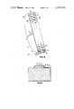
- FIG. 4 is an isometric top view of the final magnetic head assembly of this invention.
- FIG. 5 is a bottom view of a single track of the joined magnetic head assembly, depicting the thin film coil structures associated with one element of the multiple elements and tracks of the magnetic head assembly, wherein one such coil would be present on each track;
- FIG. 6 is a sectional view A--A, taken through FIG. 5.
- a rectangular ferrite block 10 is joined to a shaped ferrite section 12 by means of a high temperature glass in a fluid state to form a sandwich assembly 14.
- the ferrite section 12 includes a channel 16 that determines the back gap of the multi-element magnetic head that is being formed.
- the glass bonding layer or shim 18 serves to define transducing gaps 20a-n, respectively, for each of a multiplicity of head elements of the finished magnetic head assembly.
- the glass shim 18 also is disposed on reliefs or reference surfaces 22,24 at the ends of the ferrite block 10 to enable proper engagement of the sandwich assembly 14 with a second ferrite sandwich assembly 26.
- uniformly spaced rectangular slots 30 are machined and cut through each of the ferrite sections and glass bonds into the ferrite blocks of the sandwich assemblies, thereby forming alternating fingers or projections 28.
- the projections 28 are dimensioned to provide a close fit with the opposing slots 30, with the allowance of relatively small spacing between the projections and slots to enable insertion of a low temperature bonding glass 32 in a fluid state.
- the sandwich assemblies are aligned and positioned in engaging relation so that the relief surfaces 22 and 24 abut the opposing relief surfaces of the sandwich assembly 26. When the opposing sandwich assemblies 14 and 26 are joined, as depicted in FIG. 3, the transducing gaps 20 of each head element are aligned in seriatim along the central longitudinal axis of the joined head assembly.
- the top and bottom surfaces of the joined sandwich assemblies are lapped to achieve a low contoured head assembly, as depicted in FIG. 4.
- the top surface 33 is lapped and polished to produce a low contoured arcuate configuration, in which the vertical height from the bottom surface 34 to the contoured face is substantially less than the width or length of said head assembly.
- the bottom surface 34 of the head assembly is lapped and polished to a high degree of flatness so as to accept thin film layers that will form the conductive coil and a flux path for the magnetic head circuitry.
- the segments 35 of the head structure shown in FIG. 4 represent discrete head elements, including discrete transducing gaps 20.
- a patterned conductive thin film layer 36 which may be gold or copper for example, is vacuum deposited on the bottom surface 34 of the head assembly (see FIG. 6).
- An insulating layer 38 of Al 2 O 3 is sputter-deposited on the conductive layer 36, leaving the end portions of the layer 36 exposed.
- a thick bar type layer 40 of Permalloy, of about 3 mil thickness, is then sputter-deposited on the insulator 38 to provide a flux path for the magnetic circuit of the head. The ends of the flux path bar 40 are in intimate contact with the ferrite surface of the head assembly, as shown in FIG. 5.
- insulating layer 42 of Al 2 O 3 is deposited on the Permalloy flux path bar, still leaving the ends of the conductive layer 36 exposed.
- a second patterned conductive thin film layer 44 is then formed by vacuum deposition, by way of example, so as to connect with the exposed ends of the first conductive layer 36, thereby closing a conductive path which is disposed around the flux bar 40.
- an insulating passivation layer 46 which may be Al 2 O 3 , is sputter-deposited to complete an assembly of the multi-turn thin film coil and flux path bar for each head element.
- the invention is not limited to the specific materials, processes or dimension recited above.
- the conductive elements of the coil may be made from aluminum or other conductive materials and may be electroplated, patterned by etching, lift-off, or plate-through instead of by vacuum deposition.
- the insulating layers may be made of polyimide or photoresist, and by photolithography and baking.
- laminated Permalloy and silicon dioxide layers may be used and may be patterned by reactive ion etching. Other changes and modifications may be made within the scope of the invention.
Abstract
Description
Claims (6)
Priority Applications (4)
| Application Number | Priority Date | Filing Date | Title |
|---|---|---|---|
| US06/245,562 US4373173A (en) | 1981-03-19 | 1981-03-19 | Multi-element head assembly |
| JP56198695A JPS57158009A (en) | 1981-03-19 | 1981-12-11 | Multi-element magnetic head |
| EP82100711A EP0060977B1 (en) | 1981-03-19 | 1982-02-02 | Method of manufacturing a multi-element magnetic transducing head |
| DE8282100711T DE3274313D1 (en) | 1981-03-19 | 1982-02-02 | Method of manufacturing a multi-element magnetic transducing head |
Applications Claiming Priority (1)
| Application Number | Priority Date | Filing Date | Title |
|---|---|---|---|
| US06/245,562 US4373173A (en) | 1981-03-19 | 1981-03-19 | Multi-element head assembly |
Publications (1)
| Publication Number | Publication Date |
|---|---|
| US4373173A true US4373173A (en) | 1983-02-08 |
Family
ID=22927165
Family Applications (1)
| Application Number | Title | Priority Date | Filing Date |
|---|---|---|---|
| US06/245,562 Expired - Fee Related US4373173A (en) | 1981-03-19 | 1981-03-19 | Multi-element head assembly |
Country Status (4)
| Country | Link |
|---|---|
| US (1) | US4373173A (en) |
| EP (1) | EP0060977B1 (en) |
| JP (1) | JPS57158009A (en) |
| DE (1) | DE3274313D1 (en) |
Cited By (9)
| Publication number | Priority date | Publication date | Assignee | Title |
|---|---|---|---|---|
| US5059278A (en) * | 1990-09-28 | 1991-10-22 | Seagate Technology | Selective chemical removal of coil seed-layer in thin film head magnetic transducer |
| US5220473A (en) * | 1991-05-08 | 1993-06-15 | Eastman Kodak Company | Multitrack magnetic head assembly having a tape-engaging surface contoured for continuous in-contact recording |
| US5506737A (en) * | 1994-07-05 | 1996-04-09 | Industrial Technology Research Institute | High-density electronic head |
| US5831798A (en) * | 1989-01-30 | 1998-11-03 | U.S. Philips Corporation | Magnetic head configured to read and/or write information on digital and analog form |
| EP0913813A2 (en) * | 1997-10-28 | 1999-05-06 | Hewlett-Packard Company | Servo write heads |
| US5995342A (en) * | 1995-08-24 | 1999-11-30 | Torohead, Inc. | Thin film heads having solenoid coils |
| US6088184A (en) * | 1998-06-16 | 2000-07-11 | International Business Machines Corporation | Apparatus and method for the control and positioning of magnetic recording heads in an azimuth recording system |
| US6195232B1 (en) | 1995-08-24 | 2001-02-27 | Torohead, Inc. | Low-noise toroidal thin film head with solenoidal coil |
| US20040001367A1 (en) * | 2002-06-28 | 2004-01-01 | Seagate Technology Llc | Increased packing density in self-organized magnetic tray |
Families Citing this family (2)
| Publication number | Priority date | Publication date | Assignee | Title |
|---|---|---|---|---|
| EP0288321A3 (en) * | 1987-04-24 | 1990-11-14 | Pioneer Electronic Corporation | Magnetic head device |
| JP2674220B2 (en) * | 1989-06-27 | 1997-11-12 | ソニー株式会社 | Manufacturing method of magnetic head |
Citations (3)
| Publication number | Priority date | Publication date | Assignee | Title |
|---|---|---|---|---|
| US3925884A (en) * | 1972-12-29 | 1975-12-16 | Derek Frank Case | Method of manufacturing multi-track magnetic heads |
| US3986210A (en) * | 1973-02-20 | 1976-10-12 | Matsushita Electric Industrial Co., Ltd. | Magnetic head device using printed circuit techniques |
| US4217613A (en) * | 1978-11-06 | 1980-08-12 | Rca Corporation | Magnetic transducer head core |
Family Cites Families (7)
| Publication number | Priority date | Publication date | Assignee | Title |
|---|---|---|---|---|
| US3353261A (en) * | 1964-12-30 | 1967-11-21 | Ibm | Method of making a multitrack magnetic transducer head |
| US3626396A (en) * | 1968-10-03 | 1971-12-07 | Ibm | Thin-film magnetic recording head |
| JPS5039920A (en) * | 1973-08-15 | 1975-04-12 | ||
| JPS50115811A (en) * | 1974-02-23 | 1975-09-10 | ||
| JPS51113721A (en) * | 1975-03-31 | 1976-10-07 | Hitachi Ltd | Production method of magnetic head |
| US4084199A (en) * | 1976-10-26 | 1978-04-11 | Spin Physics, Inc. | High density multitrack magnetic head |
| US4357640A (en) * | 1980-10-24 | 1982-11-02 | Nortronics Company, Inc. | Thin film magnetic transducer |
-
1981
- 1981-03-19 US US06/245,562 patent/US4373173A/en not_active Expired - Fee Related
- 1981-12-11 JP JP56198695A patent/JPS57158009A/en active Pending
-
1982
- 1982-02-02 DE DE8282100711T patent/DE3274313D1/en not_active Expired
- 1982-02-02 EP EP82100711A patent/EP0060977B1/en not_active Expired
Patent Citations (3)
| Publication number | Priority date | Publication date | Assignee | Title |
|---|---|---|---|---|
| US3925884A (en) * | 1972-12-29 | 1975-12-16 | Derek Frank Case | Method of manufacturing multi-track magnetic heads |
| US3986210A (en) * | 1973-02-20 | 1976-10-12 | Matsushita Electric Industrial Co., Ltd. | Magnetic head device using printed circuit techniques |
| US4217613A (en) * | 1978-11-06 | 1980-08-12 | Rca Corporation | Magnetic transducer head core |
Cited By (11)
| Publication number | Priority date | Publication date | Assignee | Title |
|---|---|---|---|---|
| US5831798A (en) * | 1989-01-30 | 1998-11-03 | U.S. Philips Corporation | Magnetic head configured to read and/or write information on digital and analog form |
| US5059278A (en) * | 1990-09-28 | 1991-10-22 | Seagate Technology | Selective chemical removal of coil seed-layer in thin film head magnetic transducer |
| US5220473A (en) * | 1991-05-08 | 1993-06-15 | Eastman Kodak Company | Multitrack magnetic head assembly having a tape-engaging surface contoured for continuous in-contact recording |
| US5506737A (en) * | 1994-07-05 | 1996-04-09 | Industrial Technology Research Institute | High-density electronic head |
| US5995342A (en) * | 1995-08-24 | 1999-11-30 | Torohead, Inc. | Thin film heads having solenoid coils |
| US6195232B1 (en) | 1995-08-24 | 2001-02-27 | Torohead, Inc. | Low-noise toroidal thin film head with solenoidal coil |
| EP0913813A2 (en) * | 1997-10-28 | 1999-05-06 | Hewlett-Packard Company | Servo write heads |
| EP0913813A3 (en) * | 1997-10-28 | 2000-08-30 | Hewlett-Packard Company | Servo write heads |
| US6088184A (en) * | 1998-06-16 | 2000-07-11 | International Business Machines Corporation | Apparatus and method for the control and positioning of magnetic recording heads in an azimuth recording system |
| US20040001367A1 (en) * | 2002-06-28 | 2004-01-01 | Seagate Technology Llc | Increased packing density in self-organized magnetic tray |
| US6838195B2 (en) | 2002-06-28 | 2005-01-04 | Seagate Technology Llc | Increased packing density in self-organized magnetic tray |
Also Published As
| Publication number | Publication date |
|---|---|
| EP0060977A2 (en) | 1982-09-29 |
| EP0060977B1 (en) | 1986-11-12 |
| DE3274313D1 (en) | 1987-01-02 |
| EP0060977A3 (en) | 1983-02-16 |
| JPS57158009A (en) | 1982-09-29 |
Similar Documents
| Publication | Publication Date | Title |
|---|---|---|
| US3549825A (en) | Magnetic transducer with planar spiral coil extending into the gap | |
| US5237476A (en) | Thin film tape head assembly | |
| EP0233086B1 (en) | Thin film magnetic head | |
| US3685144A (en) | Method of making a magnetic transducer | |
| US5142768A (en) | Method for making magnetic head with enhanced poletip | |
| CA1147855A (en) | Thin film magnetic head | |
| US3613228A (en) | Manufacture of multielement magnetic head assemblies | |
| US3940797A (en) | Shielded magnetoresistive magnetic transducer | |
| US4158213A (en) | Multitrack magnetic heads | |
| US4373173A (en) | Multi-element head assembly | |
| JPH0644333B2 (en) | Magnetic recording / reproducing head and method of manufacturing the same | |
| US6947256B2 (en) | Embedded wire planar write head system and method | |
| US4217613A (en) | Magnetic transducer head core | |
| US4044392A (en) | Process for making a read-while-write tape head and the product made thereby | |
| JP3394266B2 (en) | Method of manufacturing magnetic write / read head | |
| US5546650A (en) | Method of manufacturing a multiple track thin film recording head | |
| US4375657A (en) | Magnetic head assembly | |
| US20060050440A1 (en) | Multilayer narrow pitch tape head array | |
| US4251910A (en) | Method of making multitrack magnetic heads | |
| EP0062739B1 (en) | Multielement magnetic head assembly and method of making such assembly | |
| US4967300A (en) | Magnetic head assembly having a transverse guiding surface formed of a mixture of aluminum oxide and titanium carbide | |
| US7450340B2 (en) | Head design with overlapping coil for narrow pitch tape head | |
| US3564521A (en) | Miniature magnetic head | |
| US4701820A (en) | Slant gap thin-film head having first and second wedge-shaped structures | |
| US4625250A (en) | Multi-track magnetic head |
Legal Events
| Date | Code | Title | Description |
|---|---|---|---|
| AS | Assignment |
Owner name: INTERNATIONAL BUSINESS MACHINES CORPORATION, ARMO Free format text: ASSIGNMENT OF ASSIGNORS INTEREST.;ASSIGNORS:ROBINSON NEIL L.;SILKENSEN RALPH D.;REEL/FRAME:003873/0460 Effective date: 19810311 |
|
| MAFP | Maintenance fee payment |
Free format text: PAYMENT OF MAINTENANCE FEE, 4TH YEAR, PL 96-517 (ORIGINAL EVENT CODE: M170); ENTITY STATUS OF PATENT OWNER: LARGE ENTITY Year of fee payment: 4 |
|
| FEPP | Fee payment procedure |
Free format text: MAINTENANCE FEE REMINDER MAILED (ORIGINAL EVENT CODE: REM.); ENTITY STATUS OF PATENT OWNER: LARGE ENTITY |
|
| LAPS | Lapse for failure to pay maintenance fees | ||
| STCH | Information on status: patent discontinuation |
Free format text: PATENT EXPIRED DUE TO NONPAYMENT OF MAINTENANCE FEES UNDER 37 CFR 1.362 |
|
| FP | Lapsed due to failure to pay maintenance fee |
Effective date: 19910210 |