US4400790A - Transversal correlator - Google Patents
Transversal correlator Download PDFInfo
- Publication number
- US4400790A US4400790A US06/222,992 US22299281A US4400790A US 4400790 A US4400790 A US 4400790A US 22299281 A US22299281 A US 22299281A US 4400790 A US4400790 A US 4400790A
- Authority
- US
- United States
- Prior art keywords
- register
- circulating
- bit sequence
- signal
- correlation
- Prior art date
- Legal status (The legal status is an assumption and is not a legal conclusion. Google has not performed a legal analysis and makes no representation as to the accuracy of the status listed.)
- Expired - Lifetime
Links
Images


Classifications
-
- G—PHYSICS
- G06—COMPUTING; CALCULATING OR COUNTING
- G06J—HYBRID COMPUTING ARRANGEMENTS
- G06J1/00—Hybrid computing arrangements
- G06J1/005—Hybrid computing arrangements for correlation; for convolution; for Z or Fourier Transform
Definitions
- the present invention pertains to the decoding of electronic signals and more particularly to the correlation of a received signal with a stored reference signal.
- the receiver In communication systems using spread spectrum techniques, the receiver must be rapidly synchronized to the spread spectrum sequence of the incoming signal.
- a despreading correlator in the receiver must be activated with sufficiently accurate synchronization to the incoming spread signal such that the timing in the receiver can be set for synchronism with the incoming signal. It has heretofore frequently been the practice to achieve synchronization by comparing the incoming spread spectrum sequence to a corresponding stored reference code. The incoming analog signal is sampled and the resulting samples are shifted through a correlator for comparison with a statically stored reference code. A single serial comparison technique of this type is limited in its effectiveness.
- CTD charge transfer device
- This specification discloses a method and apparatus for correlating an input signal with a preselected bit sequence, the input signal having spread spectrum modulation corresponding to the preselected bit sequence.
- Circuitry is provided for periodically sampling the input signal to produce a series of analog samples.
- a preset number of the analog samples are stored in storage circuits wherein each new sample replaces the oldest stored sample.
- At least a section of the preselected bit sequence is stored and circulated through a circulating register.
- Further circuitry is provided for correlating the circulating bit sequence in the circulating register with the analog samples fixed in the storage circuits to produce a correlation signal when the bit sequence in the circulating register is aligned with the corresponding sequence of analog samples in the storage circuits.
- a plurality of the subsection correlators are connected in series such that there is simultaneous correlation of differing sections of the preselected bit sequence with the incoming analog samples.
- the correlation signals produced by each of the correlation subsections are summed to produce a correlation output signal.
- FIG. 1 is a block diagram illustration of a segmented, transversal correlator with two correlation subsections in accordance with the present invention
- FIGS. 2A-2C are illustrations of analog sample storage and transfer together with the clocking of a reference code through a circulating register to provide alignment between the samples of the incoming signal and the stored reference code;
- FIG. 3 is a schematic illustration of a circuit for providing sampling of the incoming signal together with storage of the samples for a delay period;
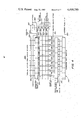
- FIG. 4 is a schematic illustration of the process of correlation wherein the reference signal code selectively connects the analog signal samples to summation lines;
- FIG. 5 is a schematic illustration of two correlator subsections which have been combined to form a correlator coherent section.
- FIG. 1 A segmented, transversal correlator 10 in accordance with the present invention is illustrated in FIG. 1.
- the correlator 10 comprises a plurality of correlator subsections as illustrated by subsections 12 and 14. All of the correlator subsections contain the same physical elements but each subsection operates independently in processing the input signal.
- PN pseudorandom noise
- a reference PN code is input through a line 20 into the register 16.
- the reference PN code is shifted through the register 16 by the clock signal received through line 18.
- Conventional circuitry not shown, generates the reference PN code which comprises a pseudorandom sequence of bits.
- the reference PN code can be changed as desired and also can have differing lengths.
- a circulating register 22 has the same number of cells as the reference register 16 within subsection correlator 12.
- a group of lines 24 connect the corresponding cells in registers 16 and 22 such that the PN code sequence stored in register 16 can be parallel shifted into register 22.
- a line 26 connects the last cell in register 22 with the first cell of the register such that the PN code stored in the register 16 circulates continuously therein until the reference code is changed.
- the command to parallel load register 22 from register 16 is transmitted through a line 28.
- the register 22 has the data shifted therein in response to a clock signal received through line 30.
- a weighting circuit 36 comprises a plurality of stages. Each of the stages in circuit 36 is connected to a corresponding cell in register 22 through lines 38.
- the weighting circuit 36 includes summation lines 40 and 42 which transfer a summation of signals to a differential amplifier 44. Summation line 40 is connected to the inverting input of amplifier 44 and summation line 42 is connected to the noninverting input of amplifier 44.
- a group of sample and hold circuits 46 is provided for storing an analog signal sample in each of the cells thereof.
- Each of the cells of circuit 46 is connected to a corresponding section of the weighting circuit 36 through a group of lines 48.
- the analog input signal to correlator 10 is supplied through a line 50 which is connected to each of the sample and hold cells of circuit 46.
- the cells of circuit 46 are connected to either line 40 or line 42 depending upon the bit state (one or zero) in the corresponding cells of register 22.
- Correlator subsection 12 further includes an address shift register 52 which receives a periodic address pulse through a line 54 and receives a clock signal through a line 56 for shifting the address pulse through register 52.
- the address pulse is shifted through register 52, it is transferred as a sampling command signal through the lines 58 which are connected respectively between the cells of register 52 and the sample and hold cells of circuit 46.
- the address pulse transfers from one cell in register 52 to the next cell it causes the corresponding sample and hold cell in circuit 46 to sample the analog input signal on line 50 and store the analog sample in the cell of circuit 46.
- the output of differential amplifier 44 is connected through a line 59 to a magnitude detector 60 which generates an output pulse having a predetermined sense (negative or positive) regardless of the sense of the input signal.
- the magnitude detector 60 produces an output signal on line 62 for transfer to a summation circuit 64.
- Circuit 64 sums all the inputs provided thereto to produce a correlation output signal on a line 66.
- Correlation subsection 14 is physically identical to the correlation subsection 12.
- Correlation subsection 14 includes a reference code loading register 70 which receives clock signals through a line 72.
- the reference PN code signal is transmitted from the loading register 16 through a line 74 to the first cell of register 70.
- the last cell of register 70 is connected to a line 76 which transfers the reference PN code to the loading register in the next succeeding correlator subsection.
- Registers 16 and 70 are connected such that the bits of the PN code are included sequentially in registers 16 and 70.
- a circulating register 78 receives through a group of lines 80 a parallel transfer of the section of the PN code in register 70.
- a feedback line 82 connects the last cell of register 78 to the first cell of register 78.
- a parallel load command is received by register 78 through line 84.
- the clock signal for causing the PN sequence in register 78 to be circulated is received through a line 86.
- a weighting circuit 88 is connected to receive the state of the bits in the PN sequence in the register 78 through a group of lines 90.
- the weighting circuit 88 includes summation lines 92 and 94 which are connected to the inputs of a differential amplifier 96.
- Line 92 is connected to the inverting input while line 94 is connected to the noninverting input of differential amplifier 96.
- a group of sample and hold circuits 98 are connected through lines 100 to corresponding stages in the weighting circuit 88.
- the analog input signal is received through a line 102 which is connected to each of the cells of the sample and hold circuits 98.
- the analog samples in the cells of circuit 98 are summed on lines 92 and 94 depending on the state of the corresponding bits in register 78.
- the correlator subsection 14 further includes an address shift register 104 which receives a periodic address pulse through line 54 and a clock signal from line 56. Each of the cells of register 104 is connected to a corresponding circuit in the sample and hold circuits 98 through lines 106.
- Detector 110 like detector 60, serves as a fullwave rectifier which transmits an output signal through a line 112 to the summation circuit 64.
- the analog input signal is transmitted serially from correlator subsection 12 to correlator subsection 14 and from there sequentially to the remainder of the correlator subsections within the overall correlator 10.
- the analog input signal is transmitted from line 50 through an analog delay line 118.
- the analog delay line 118 has a number of cells such that the time period of the delay through circuit 118 is equal to the time period of the samples stored in the cells of circuit 46.
- a similar delay circuit 120 is connected to line 102 for supplying the analog input signal to the next sequential correlator subsection downstream from correlator subsection 14.
- the analog delay line 118 samples the analog input signal at the same rate as the sample and hold circuits 46 and 98.
- the signal received at line 50 includes the PN sequence which is synchronized to transmitted data in which the data is transmitted at a sub-multiple of the PN rate.
- FIGS. 2A-2C The flow of data through various registers of the transversal correlator 10 is shown in FIGS. 2A-2C.
- the sequential states of data are shown from left to right in FIG. 2A as data states 122, 123, 124, 125, 126, 127 and 128, in FIG. 2B as data states 129, 130, 131, 132, 133, 134 and 135 and in FIG. 2C as data states 136, 137, 138, 139, 140, 141 and 142.
- These data states are representative of a correlator having two 8-bit subsections.
- the analog data states are represented for sample and hold circuits 46 and 98 and the reference data states are shown for registers 22 and 78.
- States 122, 129, 136 and 140 represents the condition of circuit 10 at the time that the reference PN sequence is parallel shifted from the loading registers 16 and 70 into the circulating registers 22 and 78.
- the states of the PN code sequence for both the sample analog input signal and the stored PN sequence are given by the terms K, K+1, K+2, K+3 and so forth.
- the symbol X is used to represent a cell which was loaded before or at the time of the parallel transfer of a new PN sequence segment to the circulating registers 22 and 78. Note that the feedback line is shown for each of the circulating registers such that the state of the last cell is transferred in the next step to be the state of the first cell.
- States 122-142 represent the data conditions in the registers during succeeding clock periods as indicated.
- the samples of the input signal are stored statically in the cells of circuits 46 and 98. This is in contrast with the circulation of the PN sequence in registers 22 and 78. It can be seen that the reference PN sequence in registers 22 and 78 is swept past the statically stored analog samples of the input signal.
- circuitry described below there is produced a correlation pulse whenever the PN sequence in the circulating registers is aligned with the corresponding PN sequence in the analog storage cells.
- the analog storage cells 46 and 98 are filled that each new analog sample is placed in a cell to replace the oldest stored analog sample.
- each of the correlator subsections 12 and 14 produces a correlation signal on the summation lines of circuits 36 and 88 which in turn causes the generation of a signal at the output of differential amplifiers 44 and 96 to produce an input pulse for detectors 60 and 110.
- the outputs of detectors 60 and 110 are summed by circuit 64 to produce a correlation output signal which comprises the fundamental output of the transversal correlator 10.
- each circulating register receives a different section of the overall PN sequence code.
- the actual group of bit signals received may be duplicated between one correlator subsection and another.
- the analog input signal is transmitted through line 50 to the correlator subsection 12 and from line 50 to a delay line 118 where the input signal is then supplied to line 102 of correlator subsection 14.
- the delayed analog input signal is then transmitted from line 102 into a second delay circuit 120 for transfer to the next succeeding correlator subsection for similar use. This continues until the analog input signal is supplied sequentially to each of the correlator subsections.
- a sufficient number of correlator subsections may be utilized such that more than one bit of the input signal can be sampled at a given time.
- An address pulse is provided through line 54 and this address pulse is sequentially stepped through address registers 52 and 104.
- the address pulse When the address pulse is in a given cell of register 52 it causes the corresponding sample and hold circuit of the sample and hold circuits 46 to be activated to sample the incoming analog signal on line 50. And, at the same time, the analog signal is stored in the delay circuit 118 for transfer to the correlator subsection 14. Only one address pulse is present in the register 52 at any one time and a new address pulse is supplied to the register 52 when the previous address pulse is propagated out of the register 52. From this procedure it can be seen that the newest analog sample replaces the oldest stored analog sample.
- the operation of address register 104 and sample and hold circuits 98 is the same as that described for circuits 52 and 46.
- the data states in each of the cells of the circulating register 22 serve to operate switches within the weighting circuits 36 to selectively connect the lines 48 to one of the summation lines 40 and 42 depending on the corresponding digital bit (low or high) in register 22. This operation likewise occurs with circulating register 78 and weighting circuits 88.
- the analog samples in the sample and hold circuits 46 are summed on the lines 40 and 42.
- the difference in the summation signals from these two lines is produced at the output of amplifier 44.
- the reference PN sequence in register 28 is not aligned with the PN sequence of the input signal, as represented by the samples in the cells of circuit 46, the summation sums on lines 40 and 42 will be essentially random. Negative and positive analog samples will both be summed on each line. But, when the reference PN sequence in circulating register 22 aligns with the corresponding PN sequence for the analog samples in the cells of circuit 46, the summation signals on lines 40 and 42 will be of substantial amplitude with opposing polarity.
- the difference in the signals will produce a difference signal on line 59 which has an amplitude greater than that which occurs in the absence of alignment.
- the detector 60 will then produce an output signal which is provided to the summation circuit 64.
- a similar procedure occurs within correlator subsection 14 to produce an output signal on line 112 to summation circuit 64.
- the outputs from all of the correlator subsections are summed to produce the correlation output signal 66 for the transversal correlator 10.
- the resulting correlation signal can then be used to synchronize a correlation loop to decode the received signal.
- the PN sequence to be decoded can be easily changed by loading a new PN sequence code into the loading registers 16, 70 and so forth.
- the new PN sequence code is then shifted by a parallel load into the corresponding circulating registers 22, 78 and so forth.
- the transversal correlator 10 can be rapidly loaded to recognize any desired PN sequence.
- the various clock signals are controlled to operate at essentially the same rate as the PN sequence bits so that there is one sample stored for each bit. Double sampling can be achieved by using two correlators in parallel and multiplexing the signals.
- the clocks can optionally be operated at multiples of the PN sequence bit rate such that multiple samples are taken for each signal period of the received signal. In the latter case the PN reference code must be compensated accordingly to match the received PN sequence.
- FIG. 3 there is shown a schematic illustration of circuitry which integrates the sample and hold circuits with the delay lines.
- the circuitry shown in FIG. 3 corresponds to the correlation subsection 14 shown in FIG. 1.
- the weighing circuit 88 is illustrated in greater detail.
- the lines 90 from circulating register 78 are connected to control the operation of switches 144, 146, 148 and 150.
- the analog samples are provided concurrently from circuits 98 through lines 100 to switches 144-150.
- the state of the signals on lines 90 controls the operation of the switches 144-150 to selectively connect the analog samples to either of the summation lines 92 and 94.
- the address register 104 receives the address pulse which is indicated to be in the position N.
- the circuit illustrated in FIG. 3 includes four sections 154, 156, 158 and 160 each of which comprises a sample and hold circuit integral with a delay circuit.
- the analog input signal is transmitted through lines 102 to switches 162, 164, 166 and 168 which are respectively in the circuit sections 154-160.
- switches 162, 164, 166 and 168 which are respectively in the circuit sections 154-160.
- a storage capacitor is charged with the analog input signal to produce an analog sample.
- Capacitors 170, 172, 174 and 176 each have a first terminal connected respectively to the switches 162, 164, 166 and 168. The remaining terminal for each of these capacitors is connected to a common ground line 178.
- the analog samples stored on capacitors 170, 172, 174 and 176 are transmitted through amplifiers 180, 182, 184 and 186 to the inputs of switches 144, 146, 148 and 150.
- the analog samples on the storage capacitors 170, 172, 174 and 176 are also transmitted respectively through amplifiers 188, 190, 192 and 194 to switches 196, 198, 200 and 202.
- Each of the circuit sections 154, 156, 158 and 160 includes respective second storage capacitors 208, 210, 212 and 214. Each of these second storage capacitors 208, 210, 212 and 214 are connected between the common ground line 178 and switches 196, 198, 200 and 202, respectively. The charge stored on capacitors 208, 210, 212 and 214 is transmitted respectively through amplifiers 216, 218, 220 and 222, respectively, to switches 224, 226, 228 and 230.
- the switches 224, 226, 228 and 230 are each connected to a delayed analog output line 232.
- Each of the cells of register 104 is connected to control the operation of three of the switches in circuit sections 154, 156, 158 and 160.
- Cell 104a of register 104 is connected through a control line 238 to control the states of switches 162, 198 and 224.
- Cell 104b is connected through a line 240 to control switches 164, 200 and 226.
- Cell 104c is connected through line 242 for controlling switches 166, 202 and 228.
- Cell 104d is connected through a line 244 for controlling switches 168 and 230 together with the switch in the next sequential circuit section (not shown) which corresponds to switch 196 in circuit section 154.
- the address pulse N is propagated through register 104 in the direction indicated by arrow 246.
- the presence of an address pulse in a particular cell of register 104 causes the switches connected to that cell to be closed.
- the address pulse is shown to be in cell 104b and that switches 164, 200 and 226 are closed. The remaining switches are open.
- Each cell of register 104 corresponds to one of the circuit sections 154, 156, 158 and 160.
- the center switch which connects the charge storage capacitors, is open for the corresponding circuit section but is closed for the circuit section receiving the immediately preceding address pulse, such as shown for switch 200 within circuit section 158.
- the switch connected to the analog input line 102 When the switch connected to the analog input line 102 is closed, the amplitude of the signal on the input line is sampled by the storage capacitor which is connected to the input line through a switch. As shown in FIG. 3, the switch 164 is closed to sample the signal on line 102 by charging capacitor 172. Note that as the address pulse propagates through address shift register 104, the corresponding circuit section will have the switch connected to the analog input line closed to charge the corresponding storage capacitor.
- the center switch such as 200
- switch 200 is closed to route the analog sample on the first storage capacitor through an amplifier to the second storage capacitor within the circuit section.
- switch 200 is closed to charge capacitor 212 to the level of capacitor 174 thereby transferring the analog charge sample to capacitor 212.
- the analog sample stored on the delay storage capacitor 212 remains stored for one cycle of the address bit through register 104.
- the output switch such as output switch 226, is closed to transfer the stored analog sample onto the delayed analog output line 232. This is illustrated by the closed switch 226 which connects capacitor 210 to line 232.
- the analog sample is stored for one time period corresponding to the time required for the address pulse to propagate through register 104. This is in turn dependent upon the rate of the clock signal provided to register 104.
- the analog sample is taken from the input analog signal on line 102, it is provided through one of the amplifiers 180, 182, 184 and 186 such that it is applied to either of the summation lines 92 or 94.
- the selection of the summation line to which the analog sample is applied is determined by the state of the reference code bits on lines 90.
- the state of each of the lines 90 controls the position of the corresponding switches 144, 146, 148 and 150.
- the analog input samples stored are the most recently collected samples and each new sample is stored in place of the oldest stored sample. Further, each sample is stored for one time period of the register 104 and then transmitted through an output line to the next succeeding correlator subsection.
- FIG. 4 A further embodiment of a correlator subsection 250 in accordance with the present invention is illustrated in FIG. 4.
- a circulating reference register 252 such as described above, receives a parallel loaded input from a reference PN code loading register through lines 254. The parallel load command is supplied through a line 256. The last cell of register 252 is connected through a feedback line 258 to the first cell of register 252.
- a clock signal is input through a line 260 into the register 252 for shifting the bit sequence stored therein.
- Line 260 is further connected to the input of a divide-by-two circuit 262, the output of which controls the operation of switches 264, 266, 268 and 270.
- Each of the cells of register 252 is connected to a control line for operating a weighting switch.
- Control lines 272-286 are connected respectively to operate switches 288-302.
- the correlator subsection 250 is provided with two sets of summation lines as opposed to the single pair of summation lines shown for the previous correlator subsections in FIGS. 1 and 3.
- Summation lines 304 and 306 are connected respectively to the poles of switches 264 and 266.
- Summation lines 308 and 310 are connected respectively to the poles of switches 268 and 270.
- Summation line 304 is connected to one of the two contacts of switches 288, 292, 296 and 300.
- Summation line 306 is connected to the other of the contacts of switches 288, 292, 296 and 300.
- Summation line 308 is connected to one of the two contacts of switches 290, 294, 298 and 302.
- the summation line 310 is connected to the other of the contacts of switches 290, 294, 298 and 302.
- An analog sample and hold and delay line circuit 312 comprises a plurality of sections such as the sections 154-160 illustrated in FIG. 3. Each of the sections of circuit 312 is connected to receive the analog input signal on line 314 and produce a delayed analog sample output signal on a line 316.
- An address shift register 318 receives an address pulse through a line 320 and the address pulse is shifted through the cells of register 318 by the clock signal received through line 260. The state of each of the cells in register 318 is transmitted to a corresponding section in circuit 312 for operation of the switches in the manner described above for the circuit in FIG. 3.
- the correlator subsection 250 Operation of the correlator subsection 250 is now described in reference to FIG. 4.
- the reference PN bit sequence is transferred through a parallel load into the circulating register 252.
- the section of the PN bit sequence loaded into register 252 is circulated therein through the feedback loop 258 in response to the clock signal provided to the register.
- the correlator using the subsection 250 is designed uniquely to isolate odd and even reference PN bits. This is done by the use of the two pairs of summation lines together with the corresponding switches which are driven by the output of the divide-by-two circuit 262.
- the weighting function is carried out by the switches 288-302 in the same manner as described above wherein the state of a reference bit sets the connection of the corresponding weighting switch to connect the analog sample to one of the summation lines.
- alternating ones of the circulating register cells of register 252 are connected to operate switches connected to the two different sets of summation lines.
- the divide-by-two circuit 262 alternately connects the summation lines 304 and 306 to the even output terminals 322 and to the odd output terminals 324.
- the output signal of circuit 262 also operates switches 268 and 270 to alternately connect summation lines 308 and 310 to the even output terminals 322 and the odd output terminals 324.
- FIG. 5 A still further embodiment of the present invention is illustrated in a schematic diagram in FIG. 5.
- the circuit in FIG. 5 basically comprises two correlator subsections, as shown in FIGS. 1 and 3, which are connected together to serve as a coherent section for a correlator.
- the overall coherent section circuit is designed at a reference numeral 340.
- the coherent section includes two substantially identical circuits 342 and 344.
- a clock signal is then put on a line 346 to a PN code register 348 which receives a reference PN code on a line 350.
- Each of the cells of the register 348 is connected to a corresponding cell in a circulating register 352 through lines 354.
- the register 352 similarly has each cell thereof connected to a corresponding cell in a weighting circuit 356.
- the outputs from circuits 356 are transmitted on lines 358 and 360 to a differential amplifier 362.
- An address shift register 364 receives a clock signal on a line 366 and an address pulse on a line 368. Each of the cells of register 364 is connected to a corresponding one of a group of sample and hold circuits 370 through lines 372.
- the analog input signal as discussed above is input through a line 374 through each of the cells of the sample and hold circuits 370.
- the delayed analog input signal is transmitted through a line 376.
- the signal samples produced by the sample and hold circuits 370 are transmitted through lines 378 to each of the cells of the weighting circuit 356.
- the circulating register 352 receives a parallel load command through a line 380, a clock signal through a line 382 and the sequential PN code through a line 384.
- the second circuit section 344 of the coherent section 340 is essentially the same as section 342.
- Circuit 344 includes a PN register 390 connected through lines 392 to a circulating register 394.
- the circulating register has each cell thereof connected to a weighting circuit 396.
- Circulating register 394 is connected to the weighting circuit 396 through lines 395.
- An address register 398 is similarly connected to lines 366 and 368 and is connected through a group of lines 400 through a group of sample and hold circuits 402.
- Each of the cells of the sample and hold circuits 402 is connected to the analog input line 374.
- the delayed analog signal is transmitted from sample and hold circuits 402 to the delayed analog line 376.
- Each of the samples produced by circuit 402 is transmitted through one of the lines 404 to the respective cells of the weighting circuits 396.
- the two output lines from the weighting circuit 396 are connected to the lines 358 and 360 are input to the differential amplifier 362.
- the PN register 348 is connected to serially transfer the PN code through a line 408 to the PN register 390.
- the PN code is circulated through registers 394 and 352 and returned through a feedback path 410.
- Lines 380 and 382 are similarly connected to circulating register 394.
- correlation bits analog sample and PN code bits
- One limiting factor is the size of the available integrated circuit chips. If the limiting factor is permitted only one half of a data bit to be correlated but it were desired to correlate a complete data bit, two correlators subsections can be combined together as shown in FIG. 5.
- the PN code sequence utilized in the correlation scheme shown in FIG. 5 is double the length for each of the correlator subsections previously described.
- the address pulse is propagated serially through registers 398 and 364 to double the number of analog samples examined for each correlation cycle. Further note that there is no analog delay between the sample and hold circuits 370 and 402.
Abstract
Description
Claims (22)
Priority Applications (1)
| Application Number | Priority Date | Filing Date | Title |
|---|---|---|---|
| US06/222,992 US4400790A (en) | 1981-01-06 | 1981-01-06 | Transversal correlator |
Applications Claiming Priority (1)
| Application Number | Priority Date | Filing Date | Title |
|---|---|---|---|
| US06/222,992 US4400790A (en) | 1981-01-06 | 1981-01-06 | Transversal correlator |
Publications (1)
| Publication Number | Publication Date |
|---|---|
| US4400790A true US4400790A (en) | 1983-08-23 |
Family
ID=22834547
Family Applications (1)
| Application Number | Title | Priority Date | Filing Date |
|---|---|---|---|
| US06/222,992 Expired - Lifetime US4400790A (en) | 1981-01-06 | 1981-01-06 | Transversal correlator |
Country Status (1)
| Country | Link |
|---|---|
| US (1) | US4400790A (en) |
Cited By (49)
| Publication number | Priority date | Publication date | Assignee | Title |
|---|---|---|---|---|
| US4538281A (en) * | 1982-05-06 | 1985-08-27 | Rockwell International Corporation | Adaptive acquisition of multiple access codes |
| US4547864A (en) * | 1982-01-07 | 1985-10-15 | Canon Kabushiki Kaisha | Correlation detecting device |
| US4561089A (en) * | 1984-03-23 | 1985-12-24 | Sangamo Weston, Inc. | Correlation detectors for use in direct sequence spread spectrum signal receiver |
| US4575864A (en) * | 1983-03-07 | 1986-03-11 | E-Systems, Inc. | Digital programmable packet switch synchronizer |
| US4607375A (en) * | 1984-10-17 | 1986-08-19 | Itt Corporation | Covert communication system |
| US4644523A (en) * | 1984-03-23 | 1987-02-17 | Sangamo Weston, Inc. | System for improving signal-to-noise ratio in a direct sequence spread spectrum signal receiver |
| US4679210A (en) * | 1985-07-18 | 1987-07-07 | Itt Gilfillan, A Division Of Itt Corporation | Soft-limited digital pulse compressor |
| WO1989000279A2 (en) * | 1987-06-29 | 1989-01-12 | Hughes Aircraft Company | Analog-digital correlator |
| US4804938A (en) * | 1986-10-24 | 1989-02-14 | Sangamo Weston, Inc. | Distribution energy management system |
| US4811342A (en) * | 1985-11-12 | 1989-03-07 | Racal Data Communications Inc. | High speed analog echo canceller |
| US4864588A (en) * | 1987-02-11 | 1989-09-05 | Hillier Technologies Limited Partnership | Remote control system, components and methods |
| US4943974A (en) * | 1988-10-21 | 1990-07-24 | Geostar Corporation | Detection of burst signal transmissions |
| US4977577A (en) * | 1988-11-02 | 1990-12-11 | Axonn Corporation | Wireless alarm system |
| US5067136A (en) * | 1988-11-02 | 1991-11-19 | Axonn Corporation | Wireless alarm system |
| US5095493A (en) * | 1988-11-02 | 1992-03-10 | Axonn Corporation | Wireless alarm system |
| US5144640A (en) * | 1990-01-31 | 1992-09-01 | Futaba Denshi Kogyo K.K. | Correlation device for spectrum spread communication |
| EP0668663A1 (en) * | 1993-09-06 | 1995-08-23 | Ntt Mobile Communications Network Inc. | Sliding correlation detector |
| US5517518A (en) * | 1994-07-21 | 1996-05-14 | Digital Security Controls Ltd. | Method and arrangement for recognition of a coded transmitted signal |
| US5523758A (en) * | 1990-01-25 | 1996-06-04 | Geophysical Survey Systems, Inc. | Sliding correlator for nanosecond pulses |
| US5548613A (en) * | 1993-12-30 | 1996-08-20 | Nec Corporation | DS/CDMA receiver using moving-averaged pilot signals for weighting and phase rotation of orthogonal data symbol vectors |
| US5768306A (en) * | 1993-09-06 | 1998-06-16 | Ntt Mobile Communications Network, Inc. | Sliding correlator used in CDMA systems to establish initial synchronization |
| US5987058A (en) * | 1988-11-02 | 1999-11-16 | Axonn Corporation | Wireless alarm system |
| US6163563A (en) * | 1996-12-31 | 2000-12-19 | Lucent Technologies Inc. | Digital communication system for high-speed complex correlation |
| US6181733B1 (en) * | 1997-07-30 | 2001-01-30 | Matsushita Electric Industrial Co., Ltd. | Digital matched filter |
| US6208477B1 (en) * | 1997-06-06 | 2001-03-27 | Western Digital Corporation | Hard disk drive having a built-in self-test for measuring non-linear signal distortion |
| US6330274B1 (en) | 1998-09-08 | 2001-12-11 | University Of Hawaii | Spread-spectrum continous-time analog correlator and method therefor |
| US6631173B1 (en) * | 1996-10-16 | 2003-10-07 | Nokia Telecommunications Oy | Method and arrangement for calculating correlation |
| US20040040800A1 (en) * | 2002-07-31 | 2004-03-04 | George Anastas | System and method for providing passive haptic feedback |
| US6779009B1 (en) * | 2001-05-21 | 2004-08-17 | Rockwell Collins | Enhanced time-shared data correlator architecture and method |
| US20050275967A1 (en) * | 2004-05-27 | 2005-12-15 | Olien Neil T | Products and processes for providing haptic feedback in resistive interface devices |
| US20060021828A1 (en) * | 2004-07-29 | 2006-02-02 | Olien Neil T | Systems and methods for providing haptic feedback with position sensing |
| US20060033703A1 (en) * | 2004-08-11 | 2006-02-16 | Olien Neil T | Systems and methods for providing friction in a haptic feedback device |
| US20060038781A1 (en) * | 2004-08-20 | 2006-02-23 | Levin Michael D | Systems and methods for providing haptic effects |
| US20060044271A1 (en) * | 2004-08-24 | 2006-03-02 | Anastas George V | Magnetic actuator for providing haptic feedback |
| US20060054427A1 (en) * | 2004-09-10 | 2006-03-16 | Alexander Jasso | Systems and methods for providing a haptic device |
| US20060061558A1 (en) * | 2004-09-20 | 2006-03-23 | Danny Grant | Products and processes for providing multimodal feedback in a user interface device |
| US20060071917A1 (en) * | 2004-09-24 | 2006-04-06 | Gomez Daniel H | Systems and methods for providing a haptic device |
| US7650810B2 (en) | 2002-04-03 | 2010-01-26 | Immersion Corporation | Haptic control devices |
| US7688310B2 (en) | 1999-12-07 | 2010-03-30 | Immersion Corporation | Haptic feedback using a keyboard device |
| US7765182B2 (en) | 1996-05-21 | 2010-07-27 | Immersion Corporation | Haptic authoring |
| US7889174B2 (en) | 1997-12-03 | 2011-02-15 | Immersion Corporation | Tactile feedback interface device including display screen |
| US8157650B2 (en) | 2006-09-13 | 2012-04-17 | Immersion Corporation | Systems and methods for casino gaming haptics |
| US8803796B2 (en) | 2004-08-26 | 2014-08-12 | Immersion Corporation | Products and processes for providing haptic feedback in a user interface |
| US8917234B2 (en) | 2002-10-15 | 2014-12-23 | Immersion Corporation | Products and processes for providing force sensations in a user interface |
| US8992322B2 (en) | 2003-06-09 | 2015-03-31 | Immersion Corporation | Interactive gaming systems with haptic feedback |
| US9104791B2 (en) | 2009-05-28 | 2015-08-11 | Immersion Corporation | Systems and methods for editing a model of a physical system for a simulation |
| US9486292B2 (en) | 2008-02-14 | 2016-11-08 | Immersion Corporation | Systems and methods for real-time winding analysis for knot detection |
| US9866924B2 (en) | 2013-03-14 | 2018-01-09 | Immersion Corporation | Systems and methods for enhanced television interaction |
| US10656244B2 (en) | 2016-04-08 | 2020-05-19 | General Radar Corp. | Reconfigurable correlator (pulse compression receiver) and beam former based on multi-gigabit serial transceivers (SERDES) |
Citations (8)
| Publication number | Priority date | Publication date | Assignee | Title |
|---|---|---|---|---|
| US3412334A (en) * | 1964-05-06 | 1968-11-19 | Navy Usa | Digital correlator |
| US3432619A (en) * | 1963-07-31 | 1969-03-11 | Ibm | Random-access communication system employing pseudo-random signals |
| US3524169A (en) * | 1967-06-05 | 1970-08-11 | North American Rockwell | Impulse response correction system |
| US3599209A (en) * | 1969-10-08 | 1971-08-10 | Us Navy | Photosensitive array correlator |
| US3718813A (en) * | 1972-01-19 | 1973-02-27 | O Williams | Technique for correlation method of determining system impulse response |
| US4032885A (en) * | 1976-03-01 | 1977-06-28 | The United States Of America As Represented By The Secretary Of The Navy | Digital correlator |
| US4224679A (en) * | 1978-10-16 | 1980-09-23 | Rca Corporation | Signal correlation means |
| US4346475A (en) * | 1979-07-13 | 1982-08-24 | U.S. Philips Corporation | Data transmission system operating on the spread spectrum principle |
-
1981
- 1981-01-06 US US06/222,992 patent/US4400790A/en not_active Expired - Lifetime
Patent Citations (8)
| Publication number | Priority date | Publication date | Assignee | Title |
|---|---|---|---|---|
| US3432619A (en) * | 1963-07-31 | 1969-03-11 | Ibm | Random-access communication system employing pseudo-random signals |
| US3412334A (en) * | 1964-05-06 | 1968-11-19 | Navy Usa | Digital correlator |
| US3524169A (en) * | 1967-06-05 | 1970-08-11 | North American Rockwell | Impulse response correction system |
| US3599209A (en) * | 1969-10-08 | 1971-08-10 | Us Navy | Photosensitive array correlator |
| US3718813A (en) * | 1972-01-19 | 1973-02-27 | O Williams | Technique for correlation method of determining system impulse response |
| US4032885A (en) * | 1976-03-01 | 1977-06-28 | The United States Of America As Represented By The Secretary Of The Navy | Digital correlator |
| US4224679A (en) * | 1978-10-16 | 1980-09-23 | Rca Corporation | Signal correlation means |
| US4346475A (en) * | 1979-07-13 | 1982-08-24 | U.S. Philips Corporation | Data transmission system operating on the spread spectrum principle |
Cited By (74)
| Publication number | Priority date | Publication date | Assignee | Title |
|---|---|---|---|---|
| US4547864A (en) * | 1982-01-07 | 1985-10-15 | Canon Kabushiki Kaisha | Correlation detecting device |
| US4538281A (en) * | 1982-05-06 | 1985-08-27 | Rockwell International Corporation | Adaptive acquisition of multiple access codes |
| US4575864A (en) * | 1983-03-07 | 1986-03-11 | E-Systems, Inc. | Digital programmable packet switch synchronizer |
| US4561089A (en) * | 1984-03-23 | 1985-12-24 | Sangamo Weston, Inc. | Correlation detectors for use in direct sequence spread spectrum signal receiver |
| US4644523A (en) * | 1984-03-23 | 1987-02-17 | Sangamo Weston, Inc. | System for improving signal-to-noise ratio in a direct sequence spread spectrum signal receiver |
| US4607375A (en) * | 1984-10-17 | 1986-08-19 | Itt Corporation | Covert communication system |
| US4679210A (en) * | 1985-07-18 | 1987-07-07 | Itt Gilfillan, A Division Of Itt Corporation | Soft-limited digital pulse compressor |
| US4811342A (en) * | 1985-11-12 | 1989-03-07 | Racal Data Communications Inc. | High speed analog echo canceller |
| US4804938A (en) * | 1986-10-24 | 1989-02-14 | Sangamo Weston, Inc. | Distribution energy management system |
| US4864588A (en) * | 1987-02-11 | 1989-09-05 | Hillier Technologies Limited Partnership | Remote control system, components and methods |
| WO1989000279A2 (en) * | 1987-06-29 | 1989-01-12 | Hughes Aircraft Company | Analog-digital correlator |
| WO1989000279A3 (en) * | 1987-06-29 | 1989-02-09 | Hughes Aircraft Co | Analog-digital correlator |
| US4813006A (en) * | 1987-06-29 | 1989-03-14 | Hughes Aircraft Company | Analog-digital correlator |
| US4943974A (en) * | 1988-10-21 | 1990-07-24 | Geostar Corporation | Detection of burst signal transmissions |
| US4977577A (en) * | 1988-11-02 | 1990-12-11 | Axonn Corporation | Wireless alarm system |
| US5598427A (en) * | 1988-11-02 | 1997-01-28 | Axonn Corporation | Wireless alarm system |
| US5095493A (en) * | 1988-11-02 | 1992-03-10 | Axonn Corporation | Wireless alarm system |
| US5987058A (en) * | 1988-11-02 | 1999-11-16 | Axonn Corporation | Wireless alarm system |
| US5067136A (en) * | 1988-11-02 | 1991-11-19 | Axonn Corporation | Wireless alarm system |
| US5523758A (en) * | 1990-01-25 | 1996-06-04 | Geophysical Survey Systems, Inc. | Sliding correlator for nanosecond pulses |
| US5144640A (en) * | 1990-01-31 | 1992-09-01 | Futaba Denshi Kogyo K.K. | Correlation device for spectrum spread communication |
| US5768306A (en) * | 1993-09-06 | 1998-06-16 | Ntt Mobile Communications Network, Inc. | Sliding correlator used in CDMA systems to establish initial synchronization |
| EP0668663A4 (en) * | 1993-09-06 | 1996-11-27 | Nippon Telegraph & Telephone | Sliding correlation detector. |
| EP0668663A1 (en) * | 1993-09-06 | 1995-08-23 | Ntt Mobile Communications Network Inc. | Sliding correlation detector |
| US5548613A (en) * | 1993-12-30 | 1996-08-20 | Nec Corporation | DS/CDMA receiver using moving-averaged pilot signals for weighting and phase rotation of orthogonal data symbol vectors |
| US5517518A (en) * | 1994-07-21 | 1996-05-14 | Digital Security Controls Ltd. | Method and arrangement for recognition of a coded transmitted signal |
| US7765182B2 (en) | 1996-05-21 | 2010-07-27 | Immersion Corporation | Haptic authoring |
| US6631173B1 (en) * | 1996-10-16 | 2003-10-07 | Nokia Telecommunications Oy | Method and arrangement for calculating correlation |
| US6163563A (en) * | 1996-12-31 | 2000-12-19 | Lucent Technologies Inc. | Digital communication system for high-speed complex correlation |
| US6208477B1 (en) * | 1997-06-06 | 2001-03-27 | Western Digital Corporation | Hard disk drive having a built-in self-test for measuring non-linear signal distortion |
| US6181733B1 (en) * | 1997-07-30 | 2001-01-30 | Matsushita Electric Industrial Co., Ltd. | Digital matched filter |
| US7889174B2 (en) | 1997-12-03 | 2011-02-15 | Immersion Corporation | Tactile feedback interface device including display screen |
| US6330274B1 (en) | 1998-09-08 | 2001-12-11 | University Of Hawaii | Spread-spectrum continous-time analog correlator and method therefor |
| US7688310B2 (en) | 1999-12-07 | 2010-03-30 | Immersion Corporation | Haptic feedback using a keyboard device |
| US6779009B1 (en) * | 2001-05-21 | 2004-08-17 | Rockwell Collins | Enhanced time-shared data correlator architecture and method |
| US7650810B2 (en) | 2002-04-03 | 2010-01-26 | Immersion Corporation | Haptic control devices |
| US20080041671A1 (en) * | 2002-07-31 | 2008-02-21 | Immersion Corporation | System and Method for Providing Passive Haptic Feedback |
| US9274600B2 (en) | 2002-07-31 | 2016-03-01 | Immersion Corporation | System and method for providing passive haptic feedback |
| US20080036735A1 (en) * | 2002-07-31 | 2008-02-14 | Immersion Corporation | System and Method for Providing Passive Haptic Feedback |
| US20080036736A1 (en) * | 2002-07-31 | 2008-02-14 | Immersion Corporation | System and Method for Providing Passive Haptic Feedback |
| US8248363B2 (en) | 2002-07-31 | 2012-08-21 | Immersion Corporation | System and method for providing passive haptic feedback |
| US20040040800A1 (en) * | 2002-07-31 | 2004-03-04 | George Anastas | System and method for providing passive haptic feedback |
| US20080035435A1 (en) * | 2002-07-31 | 2008-02-14 | Immersion Corporation | System and Method for Providing Passive Haptic Feedback |
| US8917234B2 (en) | 2002-10-15 | 2014-12-23 | Immersion Corporation | Products and processes for providing force sensations in a user interface |
| US8992322B2 (en) | 2003-06-09 | 2015-03-31 | Immersion Corporation | Interactive gaming systems with haptic feedback |
| US8154512B2 (en) | 2004-05-27 | 2012-04-10 | Immersion Coporation | Products and processes for providing haptic feedback in resistive interface devices |
| US7522152B2 (en) | 2004-05-27 | 2009-04-21 | Immersion Corporation | Products and processes for providing haptic feedback in resistive interface devices |
| US20090231113A1 (en) * | 2004-05-27 | 2009-09-17 | Olien Neil T | Products and Processes For Providing Haptic Feedback In Resistive Interface Devices |
| US20050275967A1 (en) * | 2004-05-27 | 2005-12-15 | Olien Neil T | Products and processes for providing haptic feedback in resistive interface devices |
| US7198137B2 (en) | 2004-07-29 | 2007-04-03 | Immersion Corporation | Systems and methods for providing haptic feedback with position sensing |
| US20060021828A1 (en) * | 2004-07-29 | 2006-02-02 | Olien Neil T | Systems and methods for providing haptic feedback with position sensing |
| US8441433B2 (en) | 2004-08-11 | 2013-05-14 | Immersion Corporation | Systems and methods for providing friction in a haptic feedback device |
| US20060033703A1 (en) * | 2004-08-11 | 2006-02-16 | Olien Neil T | Systems and methods for providing friction in a haptic feedback device |
| US20060038781A1 (en) * | 2004-08-20 | 2006-02-23 | Levin Michael D | Systems and methods for providing haptic effects |
| US10179540B2 (en) | 2004-08-20 | 2019-01-15 | Immersion Corporation | Systems and methods for providing haptic effects |
| US9495009B2 (en) | 2004-08-20 | 2016-11-15 | Immersion Corporation | Systems and methods for providing haptic effects |
| US8013847B2 (en) | 2004-08-24 | 2011-09-06 | Immersion Corporation | Magnetic actuator for providing haptic feedback |
| US20060044271A1 (en) * | 2004-08-24 | 2006-03-02 | Anastas George V | Magnetic actuator for providing haptic feedback |
| US8803796B2 (en) | 2004-08-26 | 2014-08-12 | Immersion Corporation | Products and processes for providing haptic feedback in a user interface |
| US20060054427A1 (en) * | 2004-09-10 | 2006-03-16 | Alexander Jasso | Systems and methods for providing a haptic device |
| US8002089B2 (en) | 2004-09-10 | 2011-08-23 | Immersion Corporation | Systems and methods for providing a haptic device |
| US20060061558A1 (en) * | 2004-09-20 | 2006-03-23 | Danny Grant | Products and processes for providing multimodal feedback in a user interface device |
| US9046922B2 (en) | 2004-09-20 | 2015-06-02 | Immersion Corporation | Products and processes for providing multimodal feedback in a user interface device |
| US20100283588A1 (en) * | 2004-09-24 | 2010-11-11 | Immersion Corporation | Systems And Methods For Providing A Haptic Device |
| US7764268B2 (en) | 2004-09-24 | 2010-07-27 | Immersion Corporation | Systems and methods for providing a haptic device |
| US20060071917A1 (en) * | 2004-09-24 | 2006-04-06 | Gomez Daniel H | Systems and methods for providing a haptic device |
| US8018434B2 (en) | 2004-09-24 | 2011-09-13 | Immersion Corporation | Systems and methods for providing a haptic device |
| US8721416B2 (en) | 2006-09-13 | 2014-05-13 | Immersion Corporation | Systems and methods for casino gaming haptics |
| US8157650B2 (en) | 2006-09-13 | 2012-04-17 | Immersion Corporation | Systems and methods for casino gaming haptics |
| US9486292B2 (en) | 2008-02-14 | 2016-11-08 | Immersion Corporation | Systems and methods for real-time winding analysis for knot detection |
| US9104791B2 (en) | 2009-05-28 | 2015-08-11 | Immersion Corporation | Systems and methods for editing a model of a physical system for a simulation |
| US9866924B2 (en) | 2013-03-14 | 2018-01-09 | Immersion Corporation | Systems and methods for enhanced television interaction |
| US10656244B2 (en) | 2016-04-08 | 2020-05-19 | General Radar Corp. | Reconfigurable correlator (pulse compression receiver) and beam former based on multi-gigabit serial transceivers (SERDES) |
| EP3440479A4 (en) * | 2016-04-08 | 2020-07-29 | General Radar Corp. | Beam-forming reconfigurable correlator (pulse compression receiver) based on multi-gigabit serial transceivers (serdes) |
Similar Documents
| Publication | Publication Date | Title |
|---|---|---|
| US4400790A (en) | Transversal correlator | |
| JP3872220B2 (en) | Receiver for spread band communication system | |
| US6181733B1 (en) | Digital matched filter | |
| KR20010087153A (en) | A variable clock rate correlation circuit and method of operation | |
| KR100394417B1 (en) | Matched filter system | |
| KR19990063426A (en) | Signal Receiving Device of DS-CM Cellular System | |
| US6621855B1 (en) | Scalable spread-spectrum signal detection and acquisition processor | |
| JP3126105B2 (en) | Apparatus for soft handoff in spread spectrum communication | |
| US6516020B1 (en) | Correlator and despreading code switching method | |
| JP2000036774A (en) | Correlation detector and cdma receiver | |
| US7039091B1 (en) | Method and apparatus for implementing a two dimensional correlator | |
| KR100418266B1 (en) | Matched filter circuit | |
| KR100441733B1 (en) | Path searcher for spread spectrum receiver | |
| US7177347B2 (en) | Synchronicity detection device | |
| US6307878B1 (en) | Cellular telephony searcher | |
| JP3582976B2 (en) | Signal receiving device for DS-CDMA cellular system | |
| JP2000252873A (en) | Correlation value detecting device, spectrum reverse spreading device having the same, receiving terminal and transmitting and receiving terminal, and correlation value detecting method | |
| EP1286466A1 (en) | Matched filter | |
| JPH1117652A (en) | Frame synchronization detection circuit | |
| RU2012138C1 (en) | Device for searching pseudonoise radio signals | |
| KR100358007B1 (en) | Synchronization acquisiting apparatus for use in a cdma system | |
| JPH1155160A (en) | Spread spectrum receiver | |
| SU1506584A1 (en) | Device for asynchronous switching of digital signals | |
| RU94001388A (en) | Generator of n-digit random sequence | |
| WO2002033836A1 (en) | Match filter architecture |
Legal Events
| Date | Code | Title | Description |
|---|---|---|---|
| STCF | Information on status: patent grant |
Free format text: PATENTED CASE |
|
| FEPP | Fee payment procedure |
Free format text: MAINTENANCE FEE REMINDER MAILED (ORIGINAL EVENT CODE: REM.); ENTITY STATUS OF PATENT OWNER: LARGE ENTITY |
|
| FEPP | Fee payment procedure |
Free format text: SURCHARGE FOR LATE PAYMENT, PL 96-517 (ORIGINAL EVENT CODE: M176); ENTITY STATUS OF PATENT OWNER: LARGE ENTITY |
|
| MAFP | Maintenance fee payment |
Free format text: PAYMENT OF MAINTENANCE FEE, 4TH YEAR, PL 96-517 (ORIGINAL EVENT CODE: M170); ENTITY STATUS OF PATENT OWNER: LARGE ENTITY Year of fee payment: 4 |
|
| FEPP | Fee payment procedure |
Free format text: SURCHARGE FOR LATE PAYMENT, PL 96-517 (ORIGINAL EVENT CODE: M176); ENTITY STATUS OF PATENT OWNER: LARGE ENTITY |
|
| MAFP | Maintenance fee payment |
Free format text: PAYMENT OF MAINTENANCE FEE, 8TH YEAR, PL 96-517 (ORIGINAL EVENT CODE: M171); ENTITY STATUS OF PATENT OWNER: LARGE ENTITY Year of fee payment: 8 |
|
| FEPP | Fee payment procedure |
Free format text: PAYOR NUMBER ASSIGNED (ORIGINAL EVENT CODE: ASPN); ENTITY STATUS OF PATENT OWNER: LARGE ENTITY |
|
| MAFP | Maintenance fee payment |
Free format text: PAYMENT OF MAINTENANCE FEE, 12TH YEAR, LARGE ENTITY (ORIGINAL EVENT CODE: M185); ENTITY STATUS OF PATENT OWNER: LARGE ENTITY Year of fee payment: 12 |