US5164869A - Magnetic recording head with integrated magnetoresistive element and open yoke - Google Patents
Magnetic recording head with integrated magnetoresistive element and open yoke Download PDFInfo
- Publication number
- US5164869A US5164869A US07/661,797 US66179791A US5164869A US 5164869 A US5164869 A US 5164869A US 66179791 A US66179791 A US 66179791A US 5164869 A US5164869 A US 5164869A
- Authority
- US
- United States
- Prior art keywords
- magnetic
- magnetic yoke
- central leg
- yoke
- thin film
- Prior art date
- Legal status (The legal status is an assumption and is not a legal conclusion. Google has not performed a legal analysis and makes no representation as to the accuracy of the status listed.)
- Expired - Lifetime
Links
Images


Classifications
-
- G—PHYSICS
- G11—INFORMATION STORAGE
- G11B—INFORMATION STORAGE BASED ON RELATIVE MOVEMENT BETWEEN RECORD CARRIER AND TRANSDUCER
- G11B5/00—Recording by magnetisation or demagnetisation of a record carrier; Reproducing by magnetic means; Record carriers therefor
- G11B5/127—Structure or manufacture of heads, e.g. inductive
- G11B5/33—Structure or manufacture of flux-sensitive heads, i.e. for reproduction only; Combination of such heads with means for recording or erasing only
- G11B5/39—Structure or manufacture of flux-sensitive heads, i.e. for reproduction only; Combination of such heads with means for recording or erasing only using magneto-resistive devices or effects
- G11B5/3903—Structure or manufacture of flux-sensitive heads, i.e. for reproduction only; Combination of such heads with means for recording or erasing only using magneto-resistive devices or effects using magnetic thin film layers or their effects, the films being part of integrated structures
- G11B5/3967—Composite structural arrangements of transducers, e.g. inductive write and magnetoresistive read
Definitions
- This invention relates to magnetic heads for writing on and reading from magnetic recording media.
- Integrated head designs are also known in which the MR element is located away from the ABS.
- U.S. Pat. No. 4,300,177 shows an integrated head in which the MR element is across a gap in one leg of the yoke (FIG. 1) or in a magnetic path across the yoke (FIGS. 2 and 3).
- the prior art integrated thin film magnetic heads have not been designed with reluctances of various elements chosen so that both the read and write efficiencies are over fifty percent, the problem being that, if the MR element effectively shunts the transducing gap, the reluctance of the MR element must be low for good read efficiency and high for good write efficiency.
- an integrated inductive write, magnetoresistive (MR) read thin film magnetic head comprises an open magnetic yoke having outside legs and a central leg.
- the outer legs are overlapped at one end to form confronting pole pieces having a transducing gap between the pole pieces, and the central leg is positioned between the pole pieces at one end and joined with the outer legs at the other end to produce a symmetrical magnetic yoke structure.
- An opening is provided in the central leg and a MR element is coupled across the opening.
- a winding is provided on each of the outside legs wound in a direction so that the flux produced by equally energizing the windings is equal and in opposite directions in each of the outside legs, is additive at the transducing gap between the pole pieces, and produces no net flux through the central leg.
- the magnetization is rotated in the MR element in response to magnetic fields being read at the transducing gap.
- FIG. 1 is a simplified diagram of a magnetic disk file embodying the present invention.
- FIG. 2 is a plan view of a thin film magnetic head embodying the present invention.
- FIG. 3 is a section view taking along lines 3--3 of FIG. 2.
- FIG. 4 is a section view taken along lines 4--4 of FIG. 2.
- FIG. 5 is a view showing an alternate embodiment of the flux guide.
- FIG. 6 is a view showing another embodiment of the flux guide.
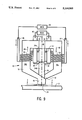
- FIG. 7 is a view showing a further embodiment of the flux guide.
- FIG. 8 is a view showing an alternate embodiment of the magnetoresistive element.
- FIG. 9 is plan view of the thin film magnetic head showing an alternate embodiment of the coils.
- FIG. 10 is a plan view of the thin film magnetic head showing a further embodiment of the coils.
- FIG. 11 is a plan view of an alternate embodiment of the thin film magnetic head embodying the present invention.
- the present invention is described as embodied in a magnetic disk file as shown in FIG. 1.
- At least one rigid rotatable magnetic disk 11 is supported on a spindle and rotated by a disk drive motor (not shown).
- the magnetic recording media on each disk is in the form of an annular pattern of concentric data tracks d as shown on disk 11.
- Each slider 13 supports one or more read/write head 10 and is attached to an actuator arm 15 by means of a suspension 17.
- the suspension 17 provides a slight spring force which biases the slider 13 against the disk surface.
- Each actuator arm 15 is attached to actuator means 19.
- the actuator means 19 shown schematically in FIG. 1 is a rotary actuator which is operable to move actuator arm 15 in a controlled manner about pivot point 21 as known in the art so that slider 13 and the associated read/write head 10 can be moved to a chosen one of the data tracks on magnetic recording medium 11.
- the rotation of the disk generates an air bearing between the slider 13 and the disk surface.
- the air bearing thus counterbalances the slight spring force of the suspension and supports the slider 13 off the disk surface during operation.
- disk files may contain a large number of disks and actuators, and that each actuator may support a number of sliders.
- the thin film magnetic head 10 comprises a first pole 12, a second pole 14 and magnetic yoke 16 which is contiguous with the second pole 14.
- a pair of coils 18 and 20 are wrapped helically about the magnetic yoke 16 and arranged so that a low reluctance magnetic circuit allows most of the magnetomotive potential applied by the coils 18, 20 to appear between first pole 12 and second pole 14 across a write gap 22.
- These elements provide a thin film magnetic write head with relatively low flux leakage between the two legs of the magnetic yoke 16 so that writing can be accomplished with high efficiency.
- a flux guide 24 is centered in the gap 22 between first pole 12 and second pole 14 and forms a relatively low reluctance path along the center of the magnetic yoke 16 between the coils 18, 20 and flux guide 24 extends to the center of the yoke 16 on the end 26 of the yoke 16 which is opposite the write gap 22.
- a gap 28 is provided in flux guide 24 at a position remote from write gap 22, and a magnetoresistive (MR) element 30 is positioned across gap 28 so that the signal flux in the flux guide 24 enters MR element 30 and significantly rotates the magnetization in the MR element 30.
- MR magnetoresistive
- the thin film magnetic head 10 is positioned closely adjacent to the magnetic recording medium 11 which may comprise a magnetic disk or tape, for example.
- the separation between the air bearing surface (ABS) 34 of the magnetic head 10 and the magnetic recording medium 11 is maintained by an air bearing formed during relative motion between the magnetic head 10 and the magnetic recording medium 11 to a spacing of a few microinches, for example.
- the structure of the magnetic head 10 at the ABS 34 (FIG. 3) comprises first pole 12 and second pole 14 separated by the write transducing gap 22.
- write transducing gap 22 is formed by first and second gap insulation layers 36, 38, the flux guide 24, and a third gap insulation layer 40.
- the lower part 24l of flux guide 24 extends from the ABS 34 to gap 28, and the upper part 24u of flux guide 24 extends from gap 28 to the end 26 of magnetic yoke 16.
- Flux guide parts 24l and 24u are both shown in FIG. 2 as having parallel sides. However, the lower part 24l' (FIG. 5) can be tapered from a width W at gap 28 to a narrower width T at ABS/34 to more easily accommodate narrow track applications.
- flux guide parts 24l and 24u are both shown in FIGS. 3 and 4 as comprising a single layer of magnetic material. However, flux guide parts 24l and 24u may comprise a laminated structure as shown in FIG. 6.
- the flux guide parts 24l and 24w comprise alternate thin layers of a ferromagnetic material 23 and a non-magnetic material 25.
- Flux guide parts 24l and 24w may also comprise a closed flux structure (FIG. 7) in which the ferromagnetic material 27 has edge closures around the non-magnetic material 29.
- the legs 16r and 16l of the magnetic yoke may also be produced with a laminated or flux closed structure, if desired.
- the MR element 30 (FIGS. 2 and 3) is normal to flux guide 24 so that the direction of current flow in the MR element is essentially parallel to the ABS 34, and the MR element is separated from flux guide 24 by the second gap insulation layer 38. Electrical conductor leads 42, 44 provide electrical contact to MR element 30, and READ control circuits 46 are coupled across conductor leads 42, 44.
- MR element 30 is shown as comprising a single layer, it is known in the art that the MR layer 30 may comprise other layers as well, such as biasing layers, for example. In addition, the MR element may require more than two conductor leads.
- the MR element 30 and electrical conductor leads 42 and 44 are arranged so that current flows substantially normal to the flux guide 24 through the MR element 30.
- This arrangement is suitable for many applications.
- the embodiment shown in FIG. 8 becomes increasingly more desirable.
- the MR element 64 is elongated in a direction along the flux guide 24".
- the electrically conducting leads 66 and 68 are arranged so that the current flow through the MR element 64 is substantially parallel to the flux guide 24". This arrangement provides increased squares of resistance for narrow track applications.
- Magnetic yoke 16 is defined as an open yoke since the two legs 16l and 16r are, for most of their length, displaced in the direction which would be the cross track direction when the magnetic head 10 is in use. In a preferred embodiment, the distance between the opposite legs 16l and 16r of the magnetic yoke 16 is more than 100 times the write gap 22 length for a majority of the length of the magnetic yoke 16. Coils 18 and 20 are fabricated helically about the legs 16l and 16r respectively of the magnetic yoke 16.
- Each of the coils 18 and 20 are provided with two electrical leads 48, 50 and 52, 54 respectively, and the sense of winding of the coils 18, 20 on legs 16l and 16r magnetic yoke 16 is opposite.
- WRITE control circuits 56 By connecting WRITE control circuits 56 across electrical leads 48 and 54 and connecting electrical leads 50 and 52 together, a WRITE current I produces a flux in the direction of arrow 58 in leg 16l of magnetic yoke 16 and produces a flux in the direction of arrow 60 in leg 16r of magnetic yoke 16.
- This flux provides a substantial magnetomotive potential difference between first pole 12 and second pole 14 which provides an efficient WRITE process.
- a sense current from READ control circuits 46 is passed through electrical leads 42 and 44 through the MR element 30.
- the sense current magnitude is selected at a level which provides a bias so that the MR element 30 is biased to a linear part of its resistance vs. magnetic flux characteristics curve.
- biasing of the MR element 30 may be by means of a current of a chosen low level magnitude in coils 18 and 20.
- biasing of the MR element may be produced by means of a current of a chosen low level magnitude in coil 18 and 20.
- a first current source 49 is connected across terminals 48 and 50, and a second current source 53 is connected across terminals 52 and 54.
- both current sources 49 and 53 produce a current I so that there is no net flux in the central leg of the magnetic yoke.
- current source 49 produces a current i
- current source 53 produces a current -i so that the resulting flux is additive in the center leg of magnetic yoke 16 where flux guide 24 is located.
- the level of current i utilized for this biasing technique is sufficiently small that the previously recorded data is not disturbed. Signals produced by resistance variation of the MR element 28 due to data previously recorded on recording medium 11 are sensed by the READ control circuits 46 as is conventionally practiced for MR sensing.
- FIG. 11 An alternate embodiment of the thin film magnetic head is shown in FIG. 11, and this is currently the preferred embodiment.
- the basic head structure remains the same as the FIG. 2 embodiment.
- the back closure 62 of the magnetic yoke 16' is in the form of an inverted V with easy axis orientation as shown by the arrows in FIG. 11.
- the easy axis orientation is established by applying a suitable magnetic field in the direction of the arrows during the deposition of the magnetic material which forms the magnetic yoke 16' and the flux guide 24'.
- the same variations in connections to the coils can be made as described above with respect to the FIG. 2 embodiment.
- the thin film magnetic head 10 is fabricated by the use of suitable deposition and patterning techniques that are known in the art.
- the bottom layer of the coils is deposited first. This is followed by a layer of insulation, either dielectric material such as alumina or hard baked resist. This layer electrically insulates the coils from the yoke structure.
- the part of the magnetic yoke which comprises first pole 12 and extends to the straight leg 16r is deposited next, followed by the deposition of an insulator layer 70 to provide a planar surface for the deposition of the other head components.
- the flux guide 24, the MR layer 30, and the electrical leads are deposited, along with the appropriate insulating layers prior to the deposition of the remainder of the magnetic yoke.
- the insulating layers include hard baked resist to insulate the coils 18, 20 and a mound 72 (FIG. 4) to define the zero throat position.
- Suitably patterned dielectric, insulating material such as alumina may also be used.
- the remainder of the magnetic yoke 16 is then deposited and this includes the second pole 14 and a contiguous structure which comprises leg 16l, back closure 26, and leg 16r which is deposited directly contacting the previously deposited layer of magnetic material which extends to first pole 12.
- vias are opened to the bottom coil layer so that the top coil layer can be deposited to provide electrical contact with the bottom coil layer and produce a coil 18 helically wrapped about leg 16l of the magnetic yoke and coil 20 helically wrapped about leg 16r of the magnetic yoke.
Abstract
Description
Claims (23)
Priority Applications (4)
| Application Number | Priority Date | Filing Date | Title |
|---|---|---|---|
| US07/661,797 US5164869A (en) | 1991-02-27 | 1991-02-27 | Magnetic recording head with integrated magnetoresistive element and open yoke |
| JP3327633A JP2500970B2 (en) | 1991-02-27 | 1991-12-11 | Magnetic recording head integrating magnetoresistive element and open yoke |
| DE69204869T DE69204869T2 (en) | 1991-02-27 | 1992-01-16 | Thin film magnetic head. |
| EP92300382A EP0501603B1 (en) | 1991-02-27 | 1992-01-16 | Thin film magnetic head |
Applications Claiming Priority (1)
| Application Number | Priority Date | Filing Date | Title |
|---|---|---|---|
| US07/661,797 US5164869A (en) | 1991-02-27 | 1991-02-27 | Magnetic recording head with integrated magnetoresistive element and open yoke |
Publications (1)
| Publication Number | Publication Date |
|---|---|
| US5164869A true US5164869A (en) | 1992-11-17 |
Family
ID=24655159
Family Applications (1)
| Application Number | Title | Priority Date | Filing Date |
|---|---|---|---|
| US07/661,797 Expired - Lifetime US5164869A (en) | 1991-02-27 | 1991-02-27 | Magnetic recording head with integrated magnetoresistive element and open yoke |
Country Status (4)
| Country | Link |
|---|---|
| US (1) | US5164869A (en) |
| EP (1) | EP0501603B1 (en) |
| JP (1) | JP2500970B2 (en) |
| DE (1) | DE69204869T2 (en) |
Cited By (23)
| Publication number | Priority date | Publication date | Assignee | Title |
|---|---|---|---|---|
| US5490027A (en) * | 1991-10-28 | 1996-02-06 | Censtor Corp. | Gimbaled micro-head/flexure/conductor assembly and system |
| US5535079A (en) * | 1991-05-30 | 1996-07-09 | Fukazawa; Toshio | Integrated thin film magnetic head |
| US5546256A (en) * | 1994-10-21 | 1996-08-13 | Seagate Technology, Inc. | Inductive transducer with closed-loop pole circumscribing I-shaped pole to reduce leakage flux |
| US5563753A (en) * | 1993-10-21 | 1996-10-08 | Seagate Technology, Inc. | Contact scheme for minimizing inductive pickup in magnetoresistive read heads |
| US5583726A (en) * | 1991-10-21 | 1996-12-10 | Fujitsu Limited | Magneto-resistive head using flux guide |
| US5748414A (en) * | 1994-06-24 | 1998-05-05 | Samsung Electro-Mechanics Co., Ltd. | Magnetoresistive element assembly with longitudinal bias |
| US5995339A (en) * | 1993-03-18 | 1999-11-30 | Fujitsu Limited | Magnetoresistive head with a front flux guide and an embedded MR element |
| US5995342A (en) * | 1995-08-24 | 1999-11-30 | Torohead, Inc. | Thin film heads having solenoid coils |
| US6195232B1 (en) * | 1995-08-24 | 2001-02-27 | Torohead, Inc. | Low-noise toroidal thin film head with solenoidal coil |
| US6219197B1 (en) * | 1994-02-10 | 2001-04-17 | International Business Machines Corporation | Method and apparatus for servo positioning in a direct access storage device with a transducer read element width greater than ⅓ and less than ½ width of a data cylinder |
| US20010037556A1 (en) * | 1999-04-26 | 2001-11-08 | Chang Thomas Young | Method of making a magnetic head assembly having open yoke write head with highly defined narrow track width |
| US6452759B2 (en) * | 1998-11-27 | 2002-09-17 | Nec Corporation | Yoke-type magnetoresistive (MR) head, yoke-type MR composite thin film head, and magnetic storage apparatus |
| US6473258B1 (en) * | 2000-09-06 | 2002-10-29 | Hitachi Electronics Engineering Co., Ltd. | Magnetic disk read/write circuit having core coils of opposite phase |
| US20020171975A1 (en) * | 2001-05-15 | 2002-11-21 | Plumer Martin L. | Writing element with no return path |
| US6600631B1 (en) | 1989-11-27 | 2003-07-29 | Censtor Corp. | Transducer/flexure/conductor structure for electromagnetic read/write system |
| US6694603B1 (en) * | 1997-06-24 | 2004-02-24 | Seagate Technology Llc | Process of forming a magnetic microactuator |
| US20040252396A1 (en) * | 2003-06-16 | 2004-12-16 | Seagate Technology Llc | Method and apparatus for mitigating thermal pole tip protrusion |
| US20050057841A1 (en) * | 2003-09-12 | 2005-03-17 | Seagate Technology Llc | Head with heating element and control regime therefor |
| US20060176601A1 (en) * | 2005-02-09 | 2006-08-10 | Seagate Technology Llc | Apparatus and method for controlling remnant magnetization in a magnetic recording head |
| US20060272146A1 (en) * | 2000-02-22 | 2006-12-07 | Yoshihiko Seyama | Magnetic sensor and method of manufacturing the same |
| US20080002294A1 (en) * | 2006-06-30 | 2008-01-03 | Kabushiki Kaisha Toshiba | Yoke-type magnetic head and magnetic disk apparatus |
| US7808746B2 (en) | 2005-08-11 | 2010-10-05 | Seagate Technology Llc | Method and apparatus for active control of spacing between a head and a storage medium |
| US8724263B2 (en) | 2005-08-11 | 2014-05-13 | Seagate Technology Llc | Method for active control of spacing between a head and a storage medium |
Families Citing this family (4)
| Publication number | Priority date | Publication date | Assignee | Title |
|---|---|---|---|---|
| JPH04362505A (en) * | 1991-02-27 | 1992-12-15 | Internatl Business Mach Corp <Ibm> | Thin-film magnetic read/write head and magnetic recording system |
| FR2761477B1 (en) * | 1997-04-01 | 1999-04-23 | Commissariat Energie Atomique | MAGNETORESISTOR MAGNETIC FIELD SENSOR |
| CN1202688A (en) * | 1997-06-02 | 1998-12-23 | 德国汤姆逊-布朗特公司 | Head drum and magnetic tape apparatus with relevant heat drum |
| WO2009098760A1 (en) * | 2008-02-06 | 2009-08-13 | Fujitsu Limited | Recording element, magnetic head, and information recording device |
Citations (4)
| Publication number | Priority date | Publication date | Assignee | Title |
|---|---|---|---|---|
| US3921217A (en) * | 1971-12-27 | 1975-11-18 | Ibm | Three-legged magnetic recording head using a magnetorestive element |
| US4300177A (en) * | 1975-07-17 | 1981-11-10 | U.S. Philips Corporation | Thin-film magnetic head for reading and writing information |
| US4566050A (en) * | 1982-12-30 | 1986-01-21 | International Business Machines Corp. (Ibm) | Skew insensitive magnetic read head |
| US4698711A (en) * | 1985-10-02 | 1987-10-06 | International Business Machines Corporation | Simplified, shielded twin-track read/write head structure |
Family Cites Families (4)
| Publication number | Priority date | Publication date | Assignee | Title |
|---|---|---|---|---|
| NL8301188A (en) * | 1983-04-05 | 1984-11-01 | Philips Nv | MAGNETIC HEAD WITH A THIN STRIP MAGNET RESISTANCE AS READING ELEMENT. |
| SU1125651A1 (en) * | 1983-06-16 | 1984-11-23 | Минский радиотехнический институт | Thin-film magnetic head |
| US4782415A (en) * | 1985-10-02 | 1988-11-01 | International Business Machines Corp. | Differential twin track vertical read/write magnetic head structure |
| NL8600390A (en) * | 1986-02-17 | 1987-09-16 | Philips Nv | MAGNETIC HEAD WITH MAGNETIC RESISTANCE ELEMENT. |
-
1991
- 1991-02-27 US US07/661,797 patent/US5164869A/en not_active Expired - Lifetime
- 1991-12-11 JP JP3327633A patent/JP2500970B2/en not_active Expired - Fee Related
-
1992
- 1992-01-16 EP EP92300382A patent/EP0501603B1/en not_active Expired - Lifetime
- 1992-01-16 DE DE69204869T patent/DE69204869T2/en not_active Expired - Fee Related
Patent Citations (4)
| Publication number | Priority date | Publication date | Assignee | Title |
|---|---|---|---|---|
| US3921217A (en) * | 1971-12-27 | 1975-11-18 | Ibm | Three-legged magnetic recording head using a magnetorestive element |
| US4300177A (en) * | 1975-07-17 | 1981-11-10 | U.S. Philips Corporation | Thin-film magnetic head for reading and writing information |
| US4566050A (en) * | 1982-12-30 | 1986-01-21 | International Business Machines Corp. (Ibm) | Skew insensitive magnetic read head |
| US4698711A (en) * | 1985-10-02 | 1987-10-06 | International Business Machines Corporation | Simplified, shielded twin-track read/write head structure |
Cited By (36)
| Publication number | Priority date | Publication date | Assignee | Title |
|---|---|---|---|---|
| US20040120078A1 (en) * | 1989-11-27 | 2004-06-24 | Berding Keith R. | Transducer/flexure/conductor structure for electromagnetic read/write system |
| US6600631B1 (en) | 1989-11-27 | 2003-07-29 | Censtor Corp. | Transducer/flexure/conductor structure for electromagnetic read/write system |
| US5535079A (en) * | 1991-05-30 | 1996-07-09 | Fukazawa; Toshio | Integrated thin film magnetic head |
| US5777827A (en) * | 1991-10-21 | 1998-07-07 | Fujitsu Limited | Horizontal type magneto-resistive head using flux guide |
| US5583726A (en) * | 1991-10-21 | 1996-12-10 | Fujitsu Limited | Magneto-resistive head using flux guide |
| US5557488A (en) * | 1991-10-28 | 1996-09-17 | Censtor Corp. | Gimbaled micro-head/flexure/conductor assembly and system |
| US5490027A (en) * | 1991-10-28 | 1996-02-06 | Censtor Corp. | Gimbaled micro-head/flexure/conductor assembly and system |
| US5995339A (en) * | 1993-03-18 | 1999-11-30 | Fujitsu Limited | Magnetoresistive head with a front flux guide and an embedded MR element |
| US5563753A (en) * | 1993-10-21 | 1996-10-08 | Seagate Technology, Inc. | Contact scheme for minimizing inductive pickup in magnetoresistive read heads |
| US6219197B1 (en) * | 1994-02-10 | 2001-04-17 | International Business Machines Corporation | Method and apparatus for servo positioning in a direct access storage device with a transducer read element width greater than ⅓ and less than ½ width of a data cylinder |
| US5748414A (en) * | 1994-06-24 | 1998-05-05 | Samsung Electro-Mechanics Co., Ltd. | Magnetoresistive element assembly with longitudinal bias |
| US5598309A (en) * | 1994-10-21 | 1997-01-28 | Seagate Technology, Inc. | Method of making inductive transducer with closed-loop pole circumscribing I-shaped pole |
| US5546256A (en) * | 1994-10-21 | 1996-08-13 | Seagate Technology, Inc. | Inductive transducer with closed-loop pole circumscribing I-shaped pole to reduce leakage flux |
| US5995342A (en) * | 1995-08-24 | 1999-11-30 | Torohead, Inc. | Thin film heads having solenoid coils |
| US6195232B1 (en) * | 1995-08-24 | 2001-02-27 | Torohead, Inc. | Low-noise toroidal thin film head with solenoidal coil |
| US6694603B1 (en) * | 1997-06-24 | 2004-02-24 | Seagate Technology Llc | Process of forming a magnetic microactuator |
| US6452759B2 (en) * | 1998-11-27 | 2002-09-17 | Nec Corporation | Yoke-type magnetoresistive (MR) head, yoke-type MR composite thin film head, and magnetic storage apparatus |
| US6725527B2 (en) * | 1999-04-26 | 2004-04-27 | Hitachi Global Storage Technologies Netherlands B.V. | Method of making a magnetic head assembly having open yoke write head with highly defined narrow track width |
| US6330128B1 (en) | 1999-04-26 | 2001-12-11 | International Business Machines Corporation | Magnetic head assembly having open yoke write head with highly defined narrow track width |
| US20010037556A1 (en) * | 1999-04-26 | 2001-11-08 | Chang Thomas Young | Method of making a magnetic head assembly having open yoke write head with highly defined narrow track width |
| US20060272146A1 (en) * | 2000-02-22 | 2006-12-07 | Yoshihiko Seyama | Magnetic sensor and method of manufacturing the same |
| US7441326B2 (en) * | 2000-02-22 | 2008-10-28 | Fujitsu Limited | Manufacturing method of a magnetic sensor |
| US6473258B1 (en) * | 2000-09-06 | 2002-10-29 | Hitachi Electronics Engineering Co., Ltd. | Magnetic disk read/write circuit having core coils of opposite phase |
| US20020171975A1 (en) * | 2001-05-15 | 2002-11-21 | Plumer Martin L. | Writing element with no return path |
| US20040252396A1 (en) * | 2003-06-16 | 2004-12-16 | Seagate Technology Llc | Method and apparatus for mitigating thermal pole tip protrusion |
| US6867940B2 (en) | 2003-06-16 | 2005-03-15 | Seagate Technology Llc | Method and apparatus for mitigating thermal pole tip protrusion |
| US6975472B2 (en) | 2003-09-12 | 2005-12-13 | Seagate Technology Llc | Head with heating element and control regime therefor |
| US20050057841A1 (en) * | 2003-09-12 | 2005-03-17 | Seagate Technology Llc | Head with heating element and control regime therefor |
| US20060176601A1 (en) * | 2005-02-09 | 2006-08-10 | Seagate Technology Llc | Apparatus and method for controlling remnant magnetization in a magnetic recording head |
| US7440213B2 (en) * | 2005-02-09 | 2008-10-21 | Seagate Technology Llc | Apparatus and method for controlling remnant magnetization in a magnetic recording head |
| US7808746B2 (en) | 2005-08-11 | 2010-10-05 | Seagate Technology Llc | Method and apparatus for active control of spacing between a head and a storage medium |
| US20100321828A1 (en) * | 2005-08-11 | 2010-12-23 | Seagate Technology Llc | Method and apparatus for active control of spacing between a head and a storage medium |
| US8208221B2 (en) | 2005-08-11 | 2012-06-26 | Seagate Technology Llc | Method and apparatus for active control of spacing between a head and a storage medium |
| US8724263B2 (en) | 2005-08-11 | 2014-05-13 | Seagate Technology Llc | Method for active control of spacing between a head and a storage medium |
| US20080002294A1 (en) * | 2006-06-30 | 2008-01-03 | Kabushiki Kaisha Toshiba | Yoke-type magnetic head and magnetic disk apparatus |
| US7848063B2 (en) * | 2006-06-30 | 2010-12-07 | Kabushiki Kaisha Toshiba | Yoke-type magnetic head and magnetic disk apparatus |
Also Published As
| Publication number | Publication date |
|---|---|
| JP2500970B2 (en) | 1996-05-29 |
| JPH0628633A (en) | 1994-02-04 |
| EP0501603B1 (en) | 1995-09-20 |
| EP0501603A2 (en) | 1992-09-02 |
| DE69204869T2 (en) | 1996-05-02 |
| DE69204869D1 (en) | 1995-10-26 |
| EP0501603A3 (en) | 1993-06-09 |
Similar Documents
| Publication | Publication Date | Title |
|---|---|---|
| US5164869A (en) | Magnetic recording head with integrated magnetoresistive element and open yoke | |
| US6621664B1 (en) | Perpendicular recording head having integrated read and write portions | |
| KR100426768B1 (en) | Magnetoresistive head | |
| US6914759B2 (en) | Giant magnetoresistive sensor having selfconsistent demagnetization fields | |
| EP0669607A2 (en) | Magnetic head assembly with MR sensor | |
| US5406433A (en) | Dual magnetoresistive head for reproducing very narrow track width short wavelength data | |
| US4644432A (en) | Three pole single element magnetic read/write head | |
| KR19980024093A (en) | Spin valve sensor with enhanced magnetoresistance | |
| JP2000105912A (en) | Magnetic tunnel joining sensor and disk driving system | |
| US5436779A (en) | Integrated yoke magnetoresistive transducer with magnetic shunt | |
| KR0162119B1 (en) | Edge biased magnetoresistive sensor | |
| KR100259431B1 (en) | Magnetoresistance sensor with enhanced magnetoresistive effect | |
| US6972932B2 (en) | High-efficiency single-turn write head for high-speed recording | |
| KR0145034B1 (en) | Peak enhanced magnetoresistive read transducer | |
| US6583970B1 (en) | Magnetoresistive head device incorporating joints between magnetoresistive layer and sense current conductors | |
| JP3183838B2 (en) | High sensitivity magnetoresistive sensor with series flux guide | |
| JPH09282618A (en) | Magneto-resistive head and magnetic recording and reproducing device | |
| US5926350A (en) | Dual gap horizontal thin film inductive head | |
| JP2002133615A (en) | Magnetoresistive head | |
| US6545847B2 (en) | Magnetoresistive effect head | |
| US6600636B1 (en) | Magnetic head with write element offset from read element | |
| JPH08115511A (en) | Flux guide type gmr head | |
| JPH11213332A (en) | Thin-film magnetic head and magnetic disk device | |
| JPH11120523A (en) | Magnetoresistive effect head | |
| EP0501617A2 (en) | Thin film magnetic read/write head |
Legal Events
| Date | Code | Title | Description |
|---|---|---|---|
| AS | Assignment |
Owner name: INTERNATIONAL BUSINESS MACHINES CORPORATION, ARMON Free format text: ASSIGNMENT OF ASSIGNORS INTEREST.;ASSIGNORS:FONTANA, ROBERT E. JR.;ROMANKIW, LUBOMYR T.;WILLIAMS, MASON L. III;REEL/FRAME:005619/0129 Effective date: 19910227 |
|
| STCF | Information on status: patent grant |
Free format text: PATENTED CASE |
|
| FPAY | Fee payment |
Year of fee payment: 4 |
|
| FPAY | Fee payment |
Year of fee payment: 8 |
|
| AS | Assignment |
Owner name: MARIANA HDD B.V., NETHERLANDS Free format text: ASSIGNMENT OF ASSIGNORS INTEREST;ASSIGNOR:INTERNATIONAL BUSINESS MACHINES CORPORATION;REEL/FRAME:013663/0348 Effective date: 20021231 |
|
| AS | Assignment |
Owner name: HITACHI GLOBAL STORAGE TECHNOLOGIES NETHERLANDS B. Free format text: CHANGE OF NAME;ASSIGNOR:MARIANA HDD B.V.;REEL/FRAME:013746/0146 Effective date: 20021231 |
|
| FEPP | Fee payment procedure |
Free format text: PAYOR NUMBER ASSIGNED (ORIGINAL EVENT CODE: ASPN); ENTITY STATUS OF PATENT OWNER: LARGE ENTITY |
|
| FPAY | Fee payment |
Year of fee payment: 12 |