US5309357A - Scintillation data collecting apparatus and method - Google Patents
Scintillation data collecting apparatus and method Download PDFInfo
- Publication number
- US5309357A US5309357A US07/826,796 US82679692A US5309357A US 5309357 A US5309357 A US 5309357A US 82679692 A US82679692 A US 82679692A US 5309357 A US5309357 A US 5309357A
- Authority
- US
- United States
- Prior art keywords
- signals
- signal
- scintillations
- intensity
- scintillation
- Prior art date
- Legal status (The legal status is an assumption and is not a legal conclusion. Google has not performed a legal analysis and makes no representation as to the accuracy of the status listed.)
- Expired - Fee Related
Links
- 238000000034 method Methods 0.000 title claims abstract description 31
- 238000006243 chemical reaction Methods 0.000 claims abstract description 49
- 238000012545 processing Methods 0.000 claims abstract description 28
- 238000005259 measurement Methods 0.000 claims description 36
- 239000013078 crystal Substances 0.000 claims description 26
- 238000004458 analytical method Methods 0.000 claims description 19
- 230000005855 radiation Effects 0.000 claims description 18
- 230000003287 optical effect Effects 0.000 claims description 9
- 230000005540 biological transmission Effects 0.000 claims description 8
- 239000000872 buffer Substances 0.000 claims description 7
- 230000003139 buffering effect Effects 0.000 claims description 5
- 238000004891 communication Methods 0.000 claims description 4
- 230000003111 delayed effect Effects 0.000 claims 2
- 230000010354 integration Effects 0.000 description 7
- 238000010586 diagram Methods 0.000 description 3
- 238000001514 detection method Methods 0.000 description 2
- 238000007476 Maximum Likelihood Methods 0.000 description 1
- 230000003321 amplification Effects 0.000 description 1
- 238000003491 array Methods 0.000 description 1
- 230000015572 biosynthetic process Effects 0.000 description 1
- 238000004364 calculation method Methods 0.000 description 1
- 238000012937 correction Methods 0.000 description 1
- 230000001934 delay Effects 0.000 description 1
- 230000001419 dependent effect Effects 0.000 description 1
- 239000003814 drug Substances 0.000 description 1
- 230000000694 effects Effects 0.000 description 1
- 238000001914 filtration Methods 0.000 description 1
- 238000002347 injection Methods 0.000 description 1
- 239000007924 injection Substances 0.000 description 1
- 230000003993 interaction Effects 0.000 description 1
- 238000003199 nucleic acid amplification method Methods 0.000 description 1
- 230000000644 propagated effect Effects 0.000 description 1
- 230000002285 radioactive effect Effects 0.000 description 1
- 238000005070 sampling Methods 0.000 description 1
- 238000012360 testing method Methods 0.000 description 1
- 229910052716 thallium Inorganic materials 0.000 description 1
- -1 thallium-activated sodium iodine Chemical class 0.000 description 1
Images


Classifications
-
- G—PHYSICS
- G01—MEASURING; TESTING
- G01T—MEASUREMENT OF NUCLEAR OR X-RADIATION
- G01T1/00—Measuring X-radiation, gamma radiation, corpuscular radiation, or cosmic radiation
- G01T1/16—Measuring radiation intensity
- G01T1/17—Circuit arrangements not adapted to a particular type of detector
-
- G—PHYSICS
- G01—MEASURING; TESTING
- G01T—MEASUREMENT OF NUCLEAR OR X-RADIATION
- G01T1/00—Measuring X-radiation, gamma radiation, corpuscular radiation, or cosmic radiation
- G01T1/16—Measuring radiation intensity
- G01T1/161—Applications in the field of nuclear medicine, e.g. in vivo counting
- G01T1/164—Scintigraphy
- G01T1/1641—Static instruments for imaging the distribution of radioactivity in one or two dimensions using one or several scintillating elements; Radio-isotope cameras
- G01T1/1647—Processing of scintigraphic data
Definitions
- the invention relates to a scintillation data collecting apparatus and a method therefor, to be used with a scintillation camera and a data processor, for efficiently collecting scintillation data produced by the scintillation camera and digitally converting the data for transmission to the data processor such that the latter computes and establishes spatial locations of the scintillations for forming a displayable image, or for storage.
- U.S. Pat. No. 4,900,931 which describes a device for locating nuclear radiation and radiation image formation device incorporating such a locating device.
- the locating device comprises a weighting means made of an arrangement of resistors for supplying analog electrical signals indicative of the position and the energy of a radiation transduced in a scintillation detected by a plurality of photodetectors.
- the analog electrical signals are then digitally converted by analog-to-digital converters so that a data processor such as a computer can process the signal for determining the location of the radiation.
- Another object of the present invention is to provide such a scintillation data collecting apparatus which achieves a data reduction so that the data processor can process the data with the required accuracy to give improved resolution and uniformity over the entire crystal of the scintillation camera.
- Another object of the invention is to provide such a scintillation data collecting apparatus which improves multiple scintillation event coincidence detection.
- Still another object of the invention is to provide such a scintillation data collecting apparatus with reduced cost in electronics while maintaining quality scintillation event detections and conversions.
- a scintillation data collecting apparatus to be used with a scintillation camera and data processing means, the camera including a crystal in which scintillations are produced at spatial locations with given intensities as a result of radiation stimuli, and a plurality of light intensity measurement devices located over a surface of the crystal for respectively collecting light from the scintillations and generating intensity signals having given amplitudes indicative of the intensities, the scintillation data collecting apparatus comprising:
- an adder for adding the intensity signals and thereby producing a sum signal, and analyzing means for carrying out a predetermined validity analysis on the sum signal and generating a resulting validity signal, the adder and the analyzing means forming a scintillation detecting means for detecting the scintillations and determining whether the scintillations are noise or valid scintillations;
- each of the conversion units having means for comparing the amplitude of the corresponding intensity signal with a threshold value and generating a resulting comparison signal, and an analog-to-digital converter for converting a signal derived from the corresponding intensity signal into the corresponding digital value signal;
- controlling means for controlling operation of each of the analog-to-digital converters depending on value of the corresponding comparison signal and the validity signal, so that the digital value signals are generated in relationship with the valid scintillations;
- each of the means for comparing comprises a plurality of comparators for comparing the amplitude of the corresponding intensity signal not only to the threshold value but also to the amplitude of each of the intensity signals produced by a group of the light intensity measurement devices close to or surrounding the light intensity measurement device which produces the corresponding intensity signal, and an AND gate having inputs receiving comparison results from the comparators and an output on which the corresponding comparison signal is generated to indicate when the corresponding intensity signal is above the threshold value and has the greatest amplitude with respect to the amplitude of the compared intensity signals, whereby the controlling means operates some of the analog-to-digital converters of the conversion units connected to the group of light intensity measurement devices such that the signals derived from the intensity signals to be converted are selected from the corresponding light energy measurement devices which are nearest to the spatial locations where the valid scintillations occur, thereby achieving a data reduction.
- a scintillation data collecting method for a scintillation camera and data processing means including a crystal in which scintillations are produced at spatial locations with given intensities as a result of radiation stimuli, and a plurality of light intensity measurement devices located over a surf ace of the crystal for respectively collecting light from the scintillations and generating intensity signals having given amplitudes indicative of the intensities, the method comprising steps of:
- the step of comparing further comprises a step of comparing individually the amplitudes of the intensity signals to the amplitude of each of the intensity signals produced by a group of the light intensity measurement devices close to or surrounding the light intensity measurement device which produces the intensity signal to compare for indicating when the intensity signal to compare is above the threshold value and has the greatest amplitude with respect to the amplitude of the compared intensity signals; and
- the step of converting further comprises a step of converting some of signals derived respectively from the intensity signals originating from the group of the light intensity measurement devices into the corresponding digital value signals;
- the signals derived from the intensity signals to be converted are selected from the corresponding light intensity measurement devices which are nearest to the spatial locations where the valid scintillations occur.
- the invention further provides an apparatus to be used with a scintillation camera and data processing means, the camera including a crystal in which scintillations are produced at spatial locations with given intensities as a result of radiation stimuli, and a plurality of light intensity measurement devices located over a surface of the crystal for respectively collecting light from the scintillations and generating intensity signals having given amplitudes indicative of the intensities, the scintillation data collecting apparatus comprising:
- an adder for adding the intensity signals and thereby producing a sum signal, and analyzing means for carrying out a predetermined validity analysis on the sum signal and generating a resulting validity signal, the adder and the analyzing means forming a scintillation detecting means for detecting the scintillations and determining whether the scintillations are noise or valid scintillations;
- each of the conversion units comprising a serial analog-to-digital converter whose output gives a most-significant bit first and a least-significant bit last and means for triggering the serial converter when the validity signal indicates that a valid scintillation has occured;
- most significant bit detector means for detecting which conversion unit is first to produce a positive bit when the validity signal indicates that a scintillation has occurred to determine which conversion unit has a large digital value signal resulting from the valid scintillation;
- reset means for controlling a reset operation of some of the analog-to-digital converters which are determined to be uninvolved in receiving signal originating from light from the scintillation based on a result from the most-significant bit detector means, and for determining which of the analog-to-digital converters have the digital value signals
- the reset means can determine which converters have useful data and reset the uninvolved converters so that they are free to convert a future intensity signal of another valid scintillation even while the converters which are involved are still converting and producing their lesser-significant bits.
- the invention also provides a method for a scintillation camera and data processing means, the camera including a crystal in which scintillations are produced at spatial locations with given intensities as a result of radiation stimuli, and a plurality of light intensity measurement devices located over a surface of the crystal for respectively collecting light from the scintillations and generating intensity signals having given amplitudes indicative of the intensities, the method comprising steps of:
- FIG. 1 is a block diagram of a scintillation data collecting apparatus according to the first preferred embodiment of the present invention
- FIG. 2 is a bubble diagram of a scintillation data collecting method according to the first preferred embodiment.
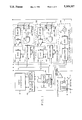
- FIG. 3 is a block diagram of a scintillation data collecting apparatus according to the fourth preferred embodiment.
- a scintillation data collecting apparatus for efficiently collecting scintillation data produced by a scintillation camera 2, and transmitting the data in a digital form to a data processor 4, such as a computer, which can process the digital scintillation data and determine thereby spatial locations of the scintillations.
- a data processor 4 such as a computer
- the application of such a scintillation data collecting apparatus enables reduction of scintillation data by sorting and digitizing with high precision the useful scintillations to provide scintillation data within the capacity of the data processor at high data rates.
- the data processor 4 can then compute an analytical function of the scintillation data according to the spatial locations of the scintillations, to be dependant on the location where the scintillation had occurred in order to optimize both resolution and uniformity over the entire crystal, and compute the locations of the scintillations.
- the scintillation camera 2 has a crystal 6 for example of thallium-activated sodium iodine in which, scintillations 8 are produced at spatial locations with given intensities respectively as a result of radiation stimuli, for instance gamma-rays 10 emitted from an isotope ingested by a patient.
- Any conventional collimator can be interposed between the crystal 6 and the radiation field for the purpose of passing mostly only the gamma-rays which originate from a specific radiation field.
- an interaction between the stimulus and the lattice structure of the crystal 6 may occur generating a pinpoint of light, i.e.
- An array of photomultipliers 12 having photocathodes acting as light intensity measurement devices are located over the surface of the crystal 6 opposite the collimator with their optical axes perpendicular thereto to collect the light emitted from the scintillations 8 and generate respectively intensity signals having given amplitudes indicative of the intensity of the scintillations 8.
- Such an array of photomultipliers 12 are normally arranged in an hexagonal packed pattern.
- Such a scintillation camera can be used to image the distribution density of radiation fields, for example, in medicine where the fields are created in patients by the injection or introduction of a radioactive pharmaceutical.
- the resultant image can yield significant medical information of value in the study, testing and treatment of a patient.
- the scintillation data collecting apparatus comprises a scintillation detector 14 which detects the scintillations 8 produced in the crystal 6 and determines whether the scintillations 8 are noise or valid scintillations.
- the scintillation detector 14 includes an adder 16 which sums the intensity signals produced by all of the photomultipliers 12. The resulting summed intensity signals are digitally converted with a flash analog-to-digital converter 18 which can convert at high speed (for example 25 MHz) with an average accuracy (for example 8 bits).
- An analyzer 20 which may be formed for example by application specific integrated circuit (ASIC) controllers, then carries out a predetermined validity analysis on the digitalized summed intensity signals to determine whether the detected scintillations 8 are noise or valid scintillations created by gamma rays of the frequency emitted by the given isotope or isotopes, and in the latter case, determines how many valid scintillations have took simultaneously place.
- ASIC application specific integrated circuit
- the scintillation data collecting apparatus also comprises a plurality of conversion units 22, each associated with a different photomultiplier 12 to digitally convert the corresponding intensity signal produced therefrom, assuming the conditions that at least one valid scintillation has been detected and that the corresponding intensity signal itself is over a threshold value, in a way to eliminate useless scintillation data.
- Each conversion unit 22 includes a comparator for comparing the amplitude of the corresponding intensity signal to a threshold value and generating a resulting comparison signal allowing conversion of the corresponding intensity signal only if the amplitude of the latter is above the threshold value. How to reduce further useless scintillation data will be described further herein.
- Each conversion unit also comprises preferably a delay 26 followed by an integrator 28 for delaying and integrating the corresponding intensity signal, thereby producing an energy signal at the output of the integrator 28.
- the main reason to do so is that since the intensity signal is almost a pulse which last for a very short time, it is easier to work with the energy rather than with the amplitude of the intensity signal.
- the delay 26 delays the pulse of the intensity signal prior to the integrator 28 to give enough time to the scintillation detector 14, the controller 32 and other components to achieve their tasks for handling properly the incoming intensity signal.
- a baseline restorer prior the integrator 28 may also be provided for suppressing a useless DC component of the intensity signal before the integration.
- a slower higher accuracy parallel analog-to-digital converter 30 (e.g.
- a controller 32 which may be formed by two controlling programmable logic arrays (PLA), in each conversion unit 22 controls operation of the analog-digital converter 30 depending on the value of the comparison signal and the validity signal generated by the analyzer 20, so that conversion is done only when a scintillation is valid and that the intensity signal is over the threshold value.
- PPA programmable logic arrays
- Amplifiers 13 having gains that can be adjusted may be provided in order to compensate for the photomultipliers 12, any other amplifiers in the circuit and analog-to-digital converters 30 variations for circuit calibration.
- the scintillation data indicative of the largest intensity signals within a desired range are provided to the data processor 4, which can further select only some of these useful data in the calculations.
- the data reduction enables the data processor 4 to be simplified if needed.
- Simultaneous scintillations in time can be handled by the scintillation data collecting apparatus without performance reduction, provided that the scintillations take place at different locations in the crystal 6.
- the analyzer 20 can analyze several scintillations and the controllers 32 can operate with two sets of control signals to control the integrators 28 and the analog-to-digital converters 30.
- the pipeline of the amplification, integration and analog-to-digital conversion allows for the simultaneous integration of the scintillation data and the conversion of the previous ones, greatly increasing the throughput of the apparatus.
- each conversion unit 22 is further provided with a plurality of comparators 34 for comparing also the amplitude of the corresponding intensity signal to each of the intensity signals produced by a group of photomultipliers 12 close to or surrounding the photomultiplier 12 which produces the corresponding intensity signal in question.
- An AND-gate 36 receives comparison results from the comparators 34 and the comparator 24 and generates the comparison signal such that it indicates when the corresponding intensity signal in question is above the threshold value and has the greatest amplitude with respect to the amplitude of the compared intensity signals resulting from the photomultipliers 12 close to or surrounding the photomultiplier 12 in question.
- the controller 32 thereby operates the corresponding analog-to-digital converter 30 and some of the analog-to-digital converters 30 of the conversion units 22 connected to the group of photomultipliers 12 such that the energy signals to be converted are selected from the photomultipliers 12 which are the nearest to the spatial locations where the valid scintillations occur.
- each controller 32 has a first input 34 receiving the comparison signal, a second input 36 receiving the validity signal, a first output 38 on which a control signal is produced for controlling the operation of the connected analog-to-digital converter 30, a second output on which a second control signal is produced for controlling the operation of the connected integrator, a third output on which a signal indicative of the activity of the controller is produced, and interconnecting means 44 to some of the controllers 32 of the conversion units 22 which are connected to the group of the photomultipliers 12 surrounding or close to the photomultiplier 12 in question for giving commands for conversion to these controllers 32.
- a serial interface 46 is provided to the apparatus for communication from the data processor 4 to the analyzer 20, by which parameters relative to the predetermined validity analysis can be modified accordingly.
- a RS-232 interface can be used for this purpose.
- the scintillation data collecting apparatus performs an efficient data reduction, letting the data processor 4 handle all the acquisition operations such as sorting and buffering the data.
- a data acquisition system 48 is further provided, the latter having buffers 50 for collecting and buffering the digital value signals, an input 52 for receiving a signal indicative of a number of detected scintillations from the analyzer 20, and an encoder for encoding the digital value signals in relationship with the photomultipliers 12 which have produced them, and finally for transmitting the resulting encoded signals to the data processor 4 preferably via an optical data transmission interface 54, for example based on an AND TAXI (trademark) chip.
- a particular scintillation data collecting method is applied to collect the scintillation data produced by the photomultipliers 12 of the scintillation camera 2 (shown in FIG. 1) and transmit the scintillation data in a digital form to the data processor 4 which can process the digital scintillation data and thereby calculate spatial locations of the scintillations.
- the method comprises steps of adding the intensity signals generated by the photomultipliers 12 and then carrying out a predetermined validity analysis on the summed intensity signals for detecting and determining whether the scintillations are noise or valid scintillations.
- a validity analysis can be carried out by determining if the scintillations fit in a preselected window of energy. This preliminary and approximate selection can be done by comparing the rise time of the energy signal derived from the summed intensity signals with the expected rise time for signals inside the window of energy. In case the scintillations are inside the acceptable range, integration of the intensity signals is started until the end of the pulsed energy signal. Determination if the scintillations are valid is made by comparing the energy of the scintillations with the defined window. If the scintillations are valid, the integration is stopped to let digital conversion take place. Otherwise, the integration is also stopped but the integrated signals are reset to zero for the next scintillations to process.
- the method comprises also a step of comparing individually the amplitudes of the intensity signal to a threshold value such that resulting comparison signals indicate if the compared intensity signals are over the threshold value.
- these intensity signals which may be meanwhile integrated for the above-described reason, are converted by means of converters 30 (shown in FIG. 1) into corresponding digital value signals indicative of the valid scintillations.
- the digital value signals generated are then computed by the data processor 4 to determine the spatial locations of valid scintillations.
- the data processor 4 can calculate coordinates of a scintillation by providing for an analytical function of the output of the photomultipliers 12 to be dependant on the location of the scintillation.
- the analytical function can be carried out entirely by logical analysis of the relative magnitude of the light intensity or signal derived thereof of the photomultipliers 12.
- the process of calculating the locations of the scintillations may be achieved in many ways, for instance by a digital centroid method or a maximum likelihood. Both ways allow dynamic corrections for errors particular to a section of the array of photomultipliers 12 while processing the scintillation data. In this way gain misadjustments in each photomultiplier 12 can be compensated for by the data processor 4.
- the step of comparing is further characterized by comparing also the amplitudes of the corresponding intensity signal to the amplitudes of each of the intensity signals produced by a group of photomultipliers 12 close to or surrounding the photomultipliers 12 which produce the compared intensity signal for indicating when the latter is not only above the threshold value but has also the greatest amplitude with respect to the amplitude of the other compared intensity signals.
- the step of converting is also characterized by not only converting the corresponding intensity signal or integrated intensity signal but also converting the other signals originating from the photomultipliers 12 which are surrounding or close to the photomultiplier in question.
- a step of delaying the intensity signals prior to a step of integrating these intensity signals gives time to carry out the operations for handling properly the intensity signals.
- steps may be added as determining which of the converters 30 (shown in FIG. 1) are converting and therefore the corresponding photomultipliers 12 associated therewith in order to read for the acquisition of the digital values to be buffered in relationship with the photomultipliers 12 while the digital conversion is in process. This can be done by setting an order in which these digital values will be buffered, reading them into a buffer 50 (shown in FIG.
- the validity signal from analyzer 20 is fed directly into the trigger inputs of the ADCs 30, and no comparator 24, AND gates 36 or controllers 32 are used. Instead, all ADCs 30 one serial ADCs and begin converting when the validity signal is received, and the data acquisition system 48 includes a first positive most-significant bit (MSB) detector.
- the first positive MSB means the first positive bit produced by the serial ADCs which produce bits in order from the MSB to the LSB.
- the system 48 detects the first positive MSB from the ADCs 30, its logic knows which ADC has a signal which is among the largest, i.e. near the center of the scintillation event 8.
- the system 48 selects a number of the ADCs 30 which are involved in the event 8 (they correspond to tubes 12 receiving light from the event 8) and allows them to continue to convert, while the remaining uninvolved Ams 30 are immediately reset.
- the reset uninvolved ADCs 30 are free to convert intensity signals resulting from a future event 8 which arrives even while the involved ADCs 30 are converting.
- the system 48 sends their digital value signals via the optical interface 54 to the data processor 4, as in the other embodiments.
- slower and more accurate serial ADCs 30 are used (e.g. [Burr Brown PCM 78P, 16-BIT, 250 kHz]) to provide an early indication of which ADC 30 corresponds to a tube 12 near the center of the event 8, and to allow for early selection of involved ADCs 30 and resetting of uninvolved ADCs 30 by system 48.
- System 48 acts as MSB detector means as well as reset means. In this way, the apparatus is able to collect data from parts of the crystal 2 where an event 8 has not occured within the time frame of conversion of the serial ADCs 30 (i.e. ⁇ 4 ⁇ s).
- the arrangement shown in FIG. 3 increases the countrate of the apparatus. If no positive bit is received after a predetermined number of bits are received from the ADCs 30, such as the first 3 bits, then the system 48 can be set to automatically reset all remaining uninvolved ADCs 30. This situation arises when a valid event 8 is detected by analyzer 20 and this event 8 is located where a previous event 8 just occured and the associated ADCs 30 are involved in conversion. Thus the remaining uninvolved ADCs 30 will indicate noise data and not generate a positive bit in the first 3 bits. The apparatus will be busy during this short period and then be ready to receive the next event 8.
Abstract
Description
Claims (20)
Priority Applications (3)
| Application Number | Priority Date | Filing Date | Title |
|---|---|---|---|
| US07/826,796 US5309357A (en) | 1992-01-28 | 1992-01-28 | Scintillation data collecting apparatus and method |
| PCT/CA1993/000035 WO1993015420A1 (en) | 1992-01-28 | 1993-01-28 | Scintillation data collecting apparatus and method |
| AU34463/93A AU3446393A (en) | 1992-01-28 | 1993-01-28 | Scintillation data collecting apparatus and method |
Applications Claiming Priority (1)
| Application Number | Priority Date | Filing Date | Title |
|---|---|---|---|
| US07/826,796 US5309357A (en) | 1992-01-28 | 1992-01-28 | Scintillation data collecting apparatus and method |
Publications (1)
| Publication Number | Publication Date |
|---|---|
| US5309357A true US5309357A (en) | 1994-05-03 |
Family
ID=25247551
Family Applications (1)
| Application Number | Title | Priority Date | Filing Date |
|---|---|---|---|
| US07/826,796 Expired - Fee Related US5309357A (en) | 1992-01-28 | 1992-01-28 | Scintillation data collecting apparatus and method |
Country Status (3)
| Country | Link |
|---|---|
| US (1) | US5309357A (en) |
| AU (1) | AU3446393A (en) |
| WO (1) | WO1993015420A1 (en) |
Cited By (61)
| Publication number | Priority date | Publication date | Assignee | Title |
|---|---|---|---|---|
| US5391880A (en) * | 1993-03-09 | 1995-02-21 | Kabushiki Kaisha Toshiba | Gamma camera system |
| US5446287A (en) * | 1994-12-13 | 1995-08-29 | Park Medical Systems Inc. | Center photodetector determination in a digital scintillation camera |
| US5493120A (en) * | 1994-10-04 | 1996-02-20 | Adac Laboratories | Apparatus and method for dual signal integration per channel |
| US5550379A (en) * | 1994-12-13 | 1996-08-27 | Park Medical Systems Inc. | Zero gain setting for discrete event processing |
| EP0706065A3 (en) * | 1994-10-03 | 1997-09-17 | Adac Lab | Improved gamma camera system |
| US6252232B1 (en) * | 1998-06-29 | 2001-06-26 | General Electric Company | Digital integrator |
| US6297490B1 (en) | 1999-06-04 | 2001-10-02 | 152 Research Inc. | Method and apparatus for determining the centre photodetector in a digital scintillation camera |
| US6639220B2 (en) | 1997-08-01 | 2003-10-28 | Is2 Research Inc. | Data reducer for a scintillation camera |
| US20090052602A1 (en) * | 2007-08-20 | 2009-02-26 | Agere Systems Inc. | Systems and Methods for Improved Timing Recovery |
| US20090052075A1 (en) * | 2007-08-20 | 2009-02-26 | Agere Systems Inc. | Systems and Methods for Improved Synchronization Between an Asynchronously Detected Signal and a Synchronous Operation |
| US20090267819A1 (en) * | 2008-04-29 | 2009-10-29 | Agere Systems Inc. | Systems and Methods for Reducing the Effects of ADC Mismatch |
| US20090268322A1 (en) * | 2008-04-29 | 2009-10-29 | Agere Systems Inc. | Systems and Methods for Acquiring Modified Rate Burst Demodulation in Servo Systems |
| US20090323214A1 (en) * | 2008-06-27 | 2009-12-31 | Agere Systems Inc. | Modulated Disk Lock Clock and Methods for Using Such |
| US20100033231A1 (en) * | 2008-08-08 | 2010-02-11 | Quesada Valentin T | High-Resolution Parametric Signal Restoration |
| WO2009112962A3 (en) * | 2008-03-13 | 2010-02-25 | Koninklijke Philips Electronics N.V. | Low-power tdc-adc and anger logic in radiation detection applications |
| US20100067628A1 (en) * | 2008-09-17 | 2010-03-18 | Lsi Corporation | Adaptive Pattern Dependent Noise Prediction on a Feed Forward Noise Estimate |
| US20100177430A1 (en) * | 2007-12-14 | 2010-07-15 | George Mathew | Systems and Methods for Fly-Height Control Using Servo Address Mark Data |
| US20100182718A1 (en) * | 2007-12-14 | 2010-07-22 | George Mathew | Systems and Methods for Adaptive CBD Estimation in a Storage Device |
| US20100202082A1 (en) * | 2008-07-28 | 2010-08-12 | Nils Graef | Systems and Methods for Variable Fly Height Measurement |
| US20100208377A1 (en) * | 2007-10-30 | 2010-08-19 | Grundvig Jeffrey P | Systems and Methods for Inter-Location Control of Storage Access |
| US20100232046A1 (en) * | 2006-05-01 | 2010-09-16 | Agere Systems Inc. | Methods and Systems for Estimating Time Corresponding to Peak Signal Amplitude |
| US20110002211A1 (en) * | 2009-07-02 | 2011-01-06 | Lsi Corporation | Systems and Methods for Format Efficient Timing Recovery In a Read Channel |
| US20110043938A1 (en) * | 2007-12-14 | 2011-02-24 | George Mathew | Systems and Methods for Fly-Height Control Using Servo Data |
| US20110157737A1 (en) * | 2009-12-31 | 2011-06-30 | Lsi Corporation | Systems and Methods for Detecting a Reference Pattern |
| US8154972B2 (en) | 2009-06-24 | 2012-04-10 | Lsi Corporation | Systems and methods for hard disk drive data storage including reduced latency loop recovery |
| US8237597B2 (en) | 2010-09-21 | 2012-08-07 | Lsi Corporation | Systems and methods for semi-independent loop processing |
| US8243381B2 (en) | 2008-11-13 | 2012-08-14 | Agere Systems Inc. | Systems and methods for sector address mark detection |
| US8261171B2 (en) | 2011-01-27 | 2012-09-04 | Lsi Corporation | Systems and methods for diversity combined data detection |
| US8325433B2 (en) | 2011-01-19 | 2012-12-04 | Lsi Corporation | Systems and methods for reduced format data processing |
| US8411385B2 (en) | 2010-12-20 | 2013-04-02 | Lsi Corporation | Systems and methods for improved timing recovery |
| US8411383B2 (en) | 2009-07-22 | 2013-04-02 | Lsi Corporation | Systems and methods for high order asymmetry correction |
| US8498072B2 (en) | 2010-11-29 | 2013-07-30 | Lsi Corporation | Systems and methods for spiral waveform detection |
| US8498071B2 (en) | 2011-06-30 | 2013-07-30 | Lsi Corporation | Systems and methods for inter-track alignment |
| US8526131B2 (en) | 2010-11-29 | 2013-09-03 | Lsi Corporation | Systems and methods for signal polarity determination |
| US8564897B1 (en) | 2012-06-21 | 2013-10-22 | Lsi Corporation | Systems and methods for enhanced sync mark detection |
| US8565047B2 (en) | 2011-04-28 | 2013-10-22 | Lsi Corporation | Systems and methods for data write loopback based timing control |
| US8566378B2 (en) | 2010-09-30 | 2013-10-22 | Lsi Corporation | Systems and methods for retry sync mark detection |
| US8566381B2 (en) | 2010-08-05 | 2013-10-22 | Lsi Corporation | Systems and methods for sequence detection in data processing |
| US8614858B2 (en) | 2010-11-15 | 2013-12-24 | Lsi Corporation | Systems and methods for sync mark detection metric computation |
| US8625216B2 (en) | 2012-06-07 | 2014-01-07 | Lsi Corporation | Servo zone detector |
| US8665544B2 (en) | 2011-05-03 | 2014-03-04 | Lsi Corporation | Systems and methods for servo data detection |
| US8669891B2 (en) | 2011-07-19 | 2014-03-11 | Lsi Corporation | Systems and methods for ADC based timing and gain control |
| US8681444B2 (en) | 2012-06-07 | 2014-03-25 | Lsi Corporation | Multi-zone servo processor |
| US8705673B2 (en) | 2008-09-05 | 2014-04-22 | Lsi Corporation | Timing phase detection using a matched filter set |
| US8749908B2 (en) | 2011-03-17 | 2014-06-10 | Lsi Corporation | Systems and methods for sync mark detection |
| US8773811B2 (en) | 2011-12-12 | 2014-07-08 | Lsi Corporation | Systems and methods for zone servo timing gain recovery |
| US8780476B2 (en) | 2011-09-23 | 2014-07-15 | Lsi Corporation | Systems and methods for controlled wedge spacing in a storage device |
| WO2014143222A1 (en) * | 2012-05-30 | 2014-09-18 | Lucerno Dynamics, Llc | System for the detection of gamma radiation from a radioactive analyte |
| US8874410B2 (en) | 2011-05-23 | 2014-10-28 | Lsi Corporation | Systems and methods for pattern detection |
| US8976475B1 (en) | 2013-11-12 | 2015-03-10 | Lsi Corporation | Systems and methods for large sector dynamic format insertion |
| US9019641B2 (en) | 2012-12-13 | 2015-04-28 | Lsi Corporation | Systems and methods for adaptive threshold pattern detection |
| US9053217B2 (en) | 2013-02-17 | 2015-06-09 | Lsi Corporation | Ratio-adjustable sync mark detection system |
| US9129646B2 (en) | 2013-09-07 | 2015-09-08 | Avago Technologies General Ip (Singapore) Pte. Ltd. | Array-reader based magnetic recording systems with mixed synchronization |
| US9129650B2 (en) | 2013-07-25 | 2015-09-08 | Avago Technologies General Ip (Singapore) Pte. Ltd. | Array-reader based magnetic recording systems with frequency division multiplexing |
| US9196297B2 (en) | 2013-03-14 | 2015-11-24 | Avago Technologies General Ip (Singapore) Pte. Ltd. | Systems and methods for enhanced sync mark mis-detection protection |
| US9224420B1 (en) | 2014-10-02 | 2015-12-29 | Avago Technologies General Ip (Singapore) Pte. Ltd. | Syncmark detection failure recovery system |
| US9275655B2 (en) | 2013-06-11 | 2016-03-01 | Avago Technologies General Ip (Singapore) Pte. Ltd. | Timing error detector with diversity loop detector decision feedback |
| US9305581B2 (en) | 2008-12-04 | 2016-04-05 | Avago Technologies General Ip (Singapore) Pte. Ltd. | Systems and methods for memory efficient repeatable run out processing |
| WO2016123231A1 (en) * | 2015-01-27 | 2016-08-04 | Oregon State University | Low-cost and low-power radiation spectrometer |
| US9939533B2 (en) | 2012-05-30 | 2018-04-10 | Lucerno Dynamics, Llc | System and method for the detection of gamma radiation from a radioactive analyte |
| US10152999B2 (en) | 2013-07-03 | 2018-12-11 | Avago Technologies International Sales Pte. Limited | Systems and methods for correlation based data alignment |
Families Citing this family (3)
| Publication number | Priority date | Publication date | Assignee | Title |
|---|---|---|---|---|
| WO1995011460A1 (en) * | 1993-10-22 | 1995-04-27 | Santa Barbara Research Center | Method and apparatus for detecting and removing corrupted data |
| FR2738693B1 (en) * | 1995-09-12 | 1997-10-10 | Commissariat Energie Atomique | PULSE PROCESSING SYSTEM ARISING FROM THE INTERACTION OF A GAMMA PARTICLE WITH A CDTE RADIATION DETECTOR |
| FR2754606B1 (en) * | 1996-10-14 | 1998-10-30 | Commissariat Energie Atomique | DEVICE AND METHOD FOR COLLECTING AND ENCODING SIGNALS FROM PHOTODETECTORS |
Citations (10)
| Publication number | Priority date | Publication date | Assignee | Title |
|---|---|---|---|---|
| US4497024A (en) * | 1981-07-01 | 1985-01-29 | General Electric Company | Nuclear image display controller |
| US4780823A (en) * | 1986-03-11 | 1988-10-25 | Siemens Gammasonics, Inc. | Multiple pixel area-weighted acquisition system for scintillation cameras |
| US4857722A (en) * | 1986-08-28 | 1989-08-15 | Shimadzu Corporation | Apparatus for stabilizing the amplification degree of photomultipliers |
| US4860205A (en) * | 1986-10-24 | 1989-08-22 | U.S. Philips Corporation | Scintillation camera processing circuitry |
| US4879464A (en) * | 1983-08-19 | 1989-11-07 | Kabushiki Kaisha Toshiba | Radiation imaging apparatus |
| US4881171A (en) * | 1986-07-09 | 1989-11-14 | U.S. Philips Corp. | Scintillation camera having simplified electronic control |
| US4900931A (en) * | 1987-05-27 | 1990-02-13 | Commissariat A L'energie Atomique | Device for locating nuclear radiation and radiation image formation device incorporating such a locating device |
| EP0450388A2 (en) * | 1990-03-30 | 1991-10-09 | Siemens Aktiengesellschaft | Scintillation camera apparatus and method implementing a localized positioning algorithm |
| GB2253274A (en) * | 1991-02-27 | 1992-09-02 | Hamamatsu Photonics Kk | Radiation position detector |
| EP0531566A1 (en) * | 1991-09-11 | 1993-03-17 | Siemens Aktiengesellschaft | Method of rapid localization with the "maximum-likelihood-estimator" in a gamma camera |
-
1992
- 1992-01-28 US US07/826,796 patent/US5309357A/en not_active Expired - Fee Related
-
1993
- 1993-01-28 WO PCT/CA1993/000035 patent/WO1993015420A1/en active Application Filing
- 1993-01-28 AU AU34463/93A patent/AU3446393A/en not_active Abandoned
Patent Citations (10)
| Publication number | Priority date | Publication date | Assignee | Title |
|---|---|---|---|---|
| US4497024A (en) * | 1981-07-01 | 1985-01-29 | General Electric Company | Nuclear image display controller |
| US4879464A (en) * | 1983-08-19 | 1989-11-07 | Kabushiki Kaisha Toshiba | Radiation imaging apparatus |
| US4780823A (en) * | 1986-03-11 | 1988-10-25 | Siemens Gammasonics, Inc. | Multiple pixel area-weighted acquisition system for scintillation cameras |
| US4881171A (en) * | 1986-07-09 | 1989-11-14 | U.S. Philips Corp. | Scintillation camera having simplified electronic control |
| US4857722A (en) * | 1986-08-28 | 1989-08-15 | Shimadzu Corporation | Apparatus for stabilizing the amplification degree of photomultipliers |
| US4860205A (en) * | 1986-10-24 | 1989-08-22 | U.S. Philips Corporation | Scintillation camera processing circuitry |
| US4900931A (en) * | 1987-05-27 | 1990-02-13 | Commissariat A L'energie Atomique | Device for locating nuclear radiation and radiation image formation device incorporating such a locating device |
| EP0450388A2 (en) * | 1990-03-30 | 1991-10-09 | Siemens Aktiengesellschaft | Scintillation camera apparatus and method implementing a localized positioning algorithm |
| GB2253274A (en) * | 1991-02-27 | 1992-09-02 | Hamamatsu Photonics Kk | Radiation position detector |
| EP0531566A1 (en) * | 1991-09-11 | 1993-03-17 | Siemens Aktiengesellschaft | Method of rapid localization with the "maximum-likelihood-estimator" in a gamma camera |
Non-Patent Citations (2)
| Title |
|---|
| Seeger, "A Fast Parallel Encoding Scheme for the Anger Camera," IEEE Transactions On Nuclear Science, vol. NS-31, No. 1, Feb. 1984, pp. 274-280. |
| Seeger, A Fast Parallel Encoding Scheme for the Anger Camera, IEEE Transactions On Nuclear Science , vol. NS 31, No. 1, Feb. 1984, pp. 274 280. * |
Cited By (88)
| Publication number | Priority date | Publication date | Assignee | Title |
|---|---|---|---|---|
| US5391880A (en) * | 1993-03-09 | 1995-02-21 | Kabushiki Kaisha Toshiba | Gamma camera system |
| EP0706065A3 (en) * | 1994-10-03 | 1997-09-17 | Adac Lab | Improved gamma camera system |
| US5493120A (en) * | 1994-10-04 | 1996-02-20 | Adac Laboratories | Apparatus and method for dual signal integration per channel |
| US5446287A (en) * | 1994-12-13 | 1995-08-29 | Park Medical Systems Inc. | Center photodetector determination in a digital scintillation camera |
| US5550379A (en) * | 1994-12-13 | 1996-08-27 | Park Medical Systems Inc. | Zero gain setting for discrete event processing |
| US6639220B2 (en) | 1997-08-01 | 2003-10-28 | Is2 Research Inc. | Data reducer for a scintillation camera |
| US6252232B1 (en) * | 1998-06-29 | 2001-06-26 | General Electric Company | Digital integrator |
| US6297490B1 (en) | 1999-06-04 | 2001-10-02 | 152 Research Inc. | Method and apparatus for determining the centre photodetector in a digital scintillation camera |
| US8059349B2 (en) | 2006-05-01 | 2011-11-15 | Agere Systems Inc. | Methods and systems for estimating time corresponding to peak signal amplitude |
| US20100232046A1 (en) * | 2006-05-01 | 2010-09-16 | Agere Systems Inc. | Methods and Systems for Estimating Time Corresponding to Peak Signal Amplitude |
| US20090052602A1 (en) * | 2007-08-20 | 2009-02-26 | Agere Systems Inc. | Systems and Methods for Improved Timing Recovery |
| US8054931B2 (en) | 2007-08-20 | 2011-11-08 | Agere Systems Inc. | Systems and methods for improved timing recovery |
| US8254049B2 (en) | 2007-08-20 | 2012-08-28 | Agere Systems Inc. | Systems and methods for improved synchronization between an asynchronously detected signal and a synchronous operation |
| US20090052075A1 (en) * | 2007-08-20 | 2009-02-26 | Agere Systems Inc. | Systems and Methods for Improved Synchronization Between an Asynchronously Detected Signal and a Synchronous Operation |
| US8174784B2 (en) | 2007-10-30 | 2012-05-08 | Agere Systems Inc. | Systems and methods for inter-location control of storage access |
| US20100208377A1 (en) * | 2007-10-30 | 2010-08-19 | Grundvig Jeffrey P | Systems and Methods for Inter-Location Control of Storage Access |
| US9305582B2 (en) | 2007-12-14 | 2016-04-05 | Avago Technologies General Ip (Singapore) Pte. Ltd. | Systems and methods for fly-height control using servo data |
| US20110043938A1 (en) * | 2007-12-14 | 2011-02-24 | George Mathew | Systems and Methods for Fly-Height Control Using Servo Data |
| US8054573B2 (en) | 2007-12-14 | 2011-11-08 | Lsi Corporation | Systems and methods for fly-height control using servo address mark data |
| US8014099B2 (en) | 2007-12-14 | 2011-09-06 | Lsi Corporation | Systems and methods for using an on-the-fly CBD estimate to adjust fly-height |
| US20100177430A1 (en) * | 2007-12-14 | 2010-07-15 | George Mathew | Systems and Methods for Fly-Height Control Using Servo Address Mark Data |
| US20100182718A1 (en) * | 2007-12-14 | 2010-07-22 | George Mathew | Systems and Methods for Adaptive CBD Estimation in a Storage Device |
| US8154818B2 (en) | 2007-12-14 | 2012-04-10 | Lsi Corporation | Systems and methods for adaptive CBD estimation in a storage device |
| US8933411B2 (en) | 2008-03-13 | 2015-01-13 | Koninklijke Philips N.V. | Low power TDC-ADC and anger logic in radiation detection applications |
| CN101971054B (en) * | 2008-03-13 | 2013-08-21 | 皇家飞利浦电子股份有限公司 | Low-power TDC-ADC and Anger logic in radiation detection applications |
| US20110001053A1 (en) * | 2008-03-13 | 2011-01-06 | Koninklijke Philips Electronics N.V. | Low-power tdc-adc and anger logic in radiation detection applications |
| JP2011513761A (en) * | 2008-03-13 | 2011-04-28 | コーニンクレッカ フィリップス エレクトロニクス エヌ ヴィ | Low power TDC-ADC and anger theory in radiation detectors |
| WO2009112962A3 (en) * | 2008-03-13 | 2010-02-25 | Koninklijke Philips Electronics N.V. | Low-power tdc-adc and anger logic in radiation detection applications |
| US8598534B2 (en) | 2008-03-13 | 2013-12-03 | Koninklijke Philips N.V. | Low-power TDC-ADC and anger logic in radiation detection applications |
| US7813065B2 (en) | 2008-04-29 | 2010-10-12 | Agere Systems Inc. | Systems and methods for acquiring modified rate burst demodulation in servo systems |
| US7768437B2 (en) * | 2008-04-29 | 2010-08-03 | Agere Systems Inc. | Systems and methods for reducing the effects of ADC mismatch |
| US20090268322A1 (en) * | 2008-04-29 | 2009-10-29 | Agere Systems Inc. | Systems and Methods for Acquiring Modified Rate Burst Demodulation in Servo Systems |
| US20090267819A1 (en) * | 2008-04-29 | 2009-10-29 | Agere Systems Inc. | Systems and Methods for Reducing the Effects of ADC Mismatch |
| US20090323214A1 (en) * | 2008-06-27 | 2009-12-31 | Agere Systems Inc. | Modulated Disk Lock Clock and Methods for Using Such |
| US20100202082A1 (en) * | 2008-07-28 | 2010-08-12 | Nils Graef | Systems and Methods for Variable Fly Height Measurement |
| US8098451B2 (en) | 2008-07-28 | 2012-01-17 | Agere Systems Inc. | Systems and methods for variable fly height measurement |
| US20110175661A1 (en) * | 2008-08-08 | 2011-07-21 | Beckman Coulter, Inc. | High-Resolution Parametric Signal Restoration |
| US20100033231A1 (en) * | 2008-08-08 | 2010-02-11 | Quesada Valentin T | High-Resolution Parametric Signal Restoration |
| US8149041B2 (en) | 2008-08-08 | 2012-04-03 | Beckman Coulter, Inc. | High-resolution parametric signal restoration |
| US7940105B2 (en) | 2008-08-08 | 2011-05-10 | Beckman Coulter, Inc. | High-resolution parametric signal restoration |
| US8705673B2 (en) | 2008-09-05 | 2014-04-22 | Lsi Corporation | Timing phase detection using a matched filter set |
| US8976913B2 (en) | 2008-09-17 | 2015-03-10 | Lsi Corporation | Adaptive pattern dependent noise prediction on a feed forward noise estimate |
| US20100067628A1 (en) * | 2008-09-17 | 2010-03-18 | Lsi Corporation | Adaptive Pattern Dependent Noise Prediction on a Feed Forward Noise Estimate |
| US8243381B2 (en) | 2008-11-13 | 2012-08-14 | Agere Systems Inc. | Systems and methods for sector address mark detection |
| US9305581B2 (en) | 2008-12-04 | 2016-04-05 | Avago Technologies General Ip (Singapore) Pte. Ltd. | Systems and methods for memory efficient repeatable run out processing |
| US8154972B2 (en) | 2009-06-24 | 2012-04-10 | Lsi Corporation | Systems and methods for hard disk drive data storage including reduced latency loop recovery |
| US20110002211A1 (en) * | 2009-07-02 | 2011-01-06 | Lsi Corporation | Systems and Methods for Format Efficient Timing Recovery In a Read Channel |
| US8174949B2 (en) | 2009-07-02 | 2012-05-08 | Lsi Corporation | Systems and methods for format efficient timing recovery in a read channel |
| US8411383B2 (en) | 2009-07-22 | 2013-04-02 | Lsi Corporation | Systems and methods for high order asymmetry correction |
| US8456775B2 (en) | 2009-12-31 | 2013-06-04 | Lsi Corporation | Systems and methods for detecting a reference pattern |
| US20110157737A1 (en) * | 2009-12-31 | 2011-06-30 | Lsi Corporation | Systems and Methods for Detecting a Reference Pattern |
| US8566381B2 (en) | 2010-08-05 | 2013-10-22 | Lsi Corporation | Systems and methods for sequence detection in data processing |
| US8237597B2 (en) | 2010-09-21 | 2012-08-07 | Lsi Corporation | Systems and methods for semi-independent loop processing |
| US8566378B2 (en) | 2010-09-30 | 2013-10-22 | Lsi Corporation | Systems and methods for retry sync mark detection |
| US8614858B2 (en) | 2010-11-15 | 2013-12-24 | Lsi Corporation | Systems and methods for sync mark detection metric computation |
| US8498072B2 (en) | 2010-11-29 | 2013-07-30 | Lsi Corporation | Systems and methods for spiral waveform detection |
| US8526131B2 (en) | 2010-11-29 | 2013-09-03 | Lsi Corporation | Systems and methods for signal polarity determination |
| US8411385B2 (en) | 2010-12-20 | 2013-04-02 | Lsi Corporation | Systems and methods for improved timing recovery |
| US8325433B2 (en) | 2011-01-19 | 2012-12-04 | Lsi Corporation | Systems and methods for reduced format data processing |
| US8261171B2 (en) | 2011-01-27 | 2012-09-04 | Lsi Corporation | Systems and methods for diversity combined data detection |
| US8749908B2 (en) | 2011-03-17 | 2014-06-10 | Lsi Corporation | Systems and methods for sync mark detection |
| US8760977B2 (en) | 2011-04-28 | 2014-06-24 | Lsi Corporation | Systems and methods for data write loopback based timing control |
| US8565047B2 (en) | 2011-04-28 | 2013-10-22 | Lsi Corporation | Systems and methods for data write loopback based timing control |
| US8665544B2 (en) | 2011-05-03 | 2014-03-04 | Lsi Corporation | Systems and methods for servo data detection |
| US8874410B2 (en) | 2011-05-23 | 2014-10-28 | Lsi Corporation | Systems and methods for pattern detection |
| US8498071B2 (en) | 2011-06-30 | 2013-07-30 | Lsi Corporation | Systems and methods for inter-track alignment |
| US8669891B2 (en) | 2011-07-19 | 2014-03-11 | Lsi Corporation | Systems and methods for ADC based timing and gain control |
| US8780476B2 (en) | 2011-09-23 | 2014-07-15 | Lsi Corporation | Systems and methods for controlled wedge spacing in a storage device |
| US8773811B2 (en) | 2011-12-12 | 2014-07-08 | Lsi Corporation | Systems and methods for zone servo timing gain recovery |
| US11668844B2 (en) | 2012-05-30 | 2023-06-06 | Lucerno Dynamics, Llc | System and method for the detection of gamma radiation from a radioactive analyte |
| US9002438B2 (en) | 2012-05-30 | 2015-04-07 | Lucerno Dynamics | System for the detection of gamma radiation from a radioactive analyte |
| WO2014143222A1 (en) * | 2012-05-30 | 2014-09-18 | Lucerno Dynamics, Llc | System for the detection of gamma radiation from a radioactive analyte |
| US10852446B2 (en) | 2012-05-30 | 2020-12-01 | Lucerno Dynamics, Llc | System and method for the detection of gamma radiation from a radioactive analyte |
| US9939533B2 (en) | 2012-05-30 | 2018-04-10 | Lucerno Dynamics, Llc | System and method for the detection of gamma radiation from a radioactive analyte |
| US8625216B2 (en) | 2012-06-07 | 2014-01-07 | Lsi Corporation | Servo zone detector |
| US8681444B2 (en) | 2012-06-07 | 2014-03-25 | Lsi Corporation | Multi-zone servo processor |
| US8564897B1 (en) | 2012-06-21 | 2013-10-22 | Lsi Corporation | Systems and methods for enhanced sync mark detection |
| US9019641B2 (en) | 2012-12-13 | 2015-04-28 | Lsi Corporation | Systems and methods for adaptive threshold pattern detection |
| US9053217B2 (en) | 2013-02-17 | 2015-06-09 | Lsi Corporation | Ratio-adjustable sync mark detection system |
| US9196297B2 (en) | 2013-03-14 | 2015-11-24 | Avago Technologies General Ip (Singapore) Pte. Ltd. | Systems and methods for enhanced sync mark mis-detection protection |
| US9275655B2 (en) | 2013-06-11 | 2016-03-01 | Avago Technologies General Ip (Singapore) Pte. Ltd. | Timing error detector with diversity loop detector decision feedback |
| US10152999B2 (en) | 2013-07-03 | 2018-12-11 | Avago Technologies International Sales Pte. Limited | Systems and methods for correlation based data alignment |
| US9129650B2 (en) | 2013-07-25 | 2015-09-08 | Avago Technologies General Ip (Singapore) Pte. Ltd. | Array-reader based magnetic recording systems with frequency division multiplexing |
| US9129646B2 (en) | 2013-09-07 | 2015-09-08 | Avago Technologies General Ip (Singapore) Pte. Ltd. | Array-reader based magnetic recording systems with mixed synchronization |
| US8976475B1 (en) | 2013-11-12 | 2015-03-10 | Lsi Corporation | Systems and methods for large sector dynamic format insertion |
| US9224420B1 (en) | 2014-10-02 | 2015-12-29 | Avago Technologies General Ip (Singapore) Pte. Ltd. | Syncmark detection failure recovery system |
| WO2016123231A1 (en) * | 2015-01-27 | 2016-08-04 | Oregon State University | Low-cost and low-power radiation spectrometer |
| US10031242B1 (en) | 2015-01-27 | 2018-07-24 | Oregon State University | Low-cost and lower-power radiation spectrometer |
Also Published As
| Publication number | Publication date |
|---|---|
| AU3446393A (en) | 1993-09-01 |
| WO1993015420A1 (en) | 1993-08-05 |
Similar Documents
| Publication | Publication Date | Title |
|---|---|---|
| US5309357A (en) | Scintillation data collecting apparatus and method | |
| US4228515A (en) | Method and apparatus of digital calibration and position analysis of a radiant emission | |
| US6936822B2 (en) | Method and apparatus to prevent signal pile-up | |
| US3872287A (en) | Method of, and apparatus for, determining radiation energy distributions | |
| US5210423A (en) | Method and apparatus for unpiling pulses generated by piled-up scintillation events | |
| JP4326493B2 (en) | Method applied to digitization of positron emission tomography (PET) radiation events | |
| US11506803B2 (en) | Method and device for processing nuclear energy spectrum | |
| US4672542A (en) | Method for processing locating pulses supplied by a gamma camera and a gamma camera utilizing this method | |
| US6576907B1 (en) | High count rate gamma camera system | |
| US5371362A (en) | Nuclear detection process with base potential correction and correspnding apparatus (particularly a gamma-camera) | |
| JP2001503527A (en) | Apparatus and method for determining an estimated location of an event associated with a photodetector assembly and application of the apparatus and method to a gamma camera | |
| JPH05203749A (en) | Position checking method of multiple scintillation event | |
| US4395635A (en) | Gamma ray coincidence analysis system | |
| US6348692B1 (en) | Device and method for nuclear locating by iterative computing of barycenter, and application to gamma-cameras | |
| GB2135451A (en) | Radiation measuring device comprising a scintillator and a photodetector | |
| JP3374596B2 (en) | Positron CT system | |
| US6333503B1 (en) | Device and process for nuclear location by weighted barycenter calculation using parallel-operating detectors, and application to gamma cameras | |
| US5952662A (en) | High event rate gamma camera | |
| US20080011955A1 (en) | Method and Apparatus for Treatment of Signals Obtained from Photomultiplier Tubes | |
| JP3903112B2 (en) | Positron lifetime measuring method and apparatus | |
| GB1595504A (en) | Method of and apparatus for monitoring the radioactivity of a sample | |
| Maier et al. | A sixteen channel peak sensing ADC for singles spectra in the FERA format | |
| JPS63148186A (en) | Light or radiation incidence position detector | |
| JP2754696B2 (en) | Gamma camera | |
| Artiges et al. | Compact CSC acquisition system: VXI D-size modules with a DSP interface |
Legal Events
| Date | Code | Title | Description |
|---|---|---|---|
| AS | Assignment |
Owner name: INDEPENDENT SCINTILLATION IMAGING SYSTEMS (ISIS) I Free format text: ASSIGNMENT OF ASSIGNORS INTEREST.;ASSIGNORS:STARK, IAIN;FERREIRA, ABEL;REEL/FRAME:005997/0610 Effective date: 19911218 Owner name: INDEPENDENT SCINTILLATION IMAGING SYSTEMS (ISIS) I Free format text: ASSIGNMENT OF ASSIGNORS INTEREST;ASSIGNORS:STARK, IAIN;FERREIRA, ABEL;REEL/FRAME:005997/0610 Effective date: 19911218 |
|
| AS | Assignment |
Owner name: PARK MEDICAL SYSTEMS INC., CANADA Free format text: CHANGE OF NAME;ASSIGNOR:INDEPENDENCE SCINTILLATION IMAGING SYSTEMS (ISIS) INC.;REEL/FRAME:007846/0065 Effective date: 19940407 |
|
| LAPS | Lapse for failure to pay maintenance fees | ||
| FP | Lapsed due to failure to pay maintenance fee |
Effective date: 19980503 |
|
| AS | Assignment |
Owner name: MIDWEST NUCLEAR, INC., OHIO Free format text: ASSIGNMENT OF ASSIGNORS INTEREST;ASSIGNOR:CARON BELANGER ERNST & YOUNG, INC., TRUSTEE TO THE BANKRUPTCY ESTATE OF PARK MEDICAL SYSTEMS, INC.;REEL/FRAME:009662/0580 Effective date: 19980904 |
|
| FEPP | Fee payment procedure |
Free format text: PETITION RELATED TO MAINTENANCE FEES FILED (ORIGINAL EVENT CODE: PMFP); ENTITY STATUS OF PATENT OWNER: LARGE ENTITY |
|
| SULP | Surcharge for late payment | ||
| FEPP | Fee payment procedure |
Free format text: PETITION RELATED TO MAINTENANCE FEES DENIED/DISMISSED (ORIGINAL EVENT CODE: PMFD); ENTITY STATUS OF PATENT OWNER: LARGE ENTITY |
|
| AS | Assignment |
Owner name: TAASCO, L.L.C., IOWA Free format text: ASSIGNMENT OF ASSIGNORS INTEREST;ASSIGNOR:MIDWEST NUCLEAR, INC.;REEL/FRAME:020174/0232 Effective date: 20051022 |
|
| AS | Assignment |
Owner name: VERISTA IMAGING, INC., IOWA Free format text: ASSIGNMENT OF ASSIGNORS INTEREST;ASSIGNOR:TAASCO, L.L.C.;REEL/FRAME:020417/0443 Effective date: 20080123 |
|
| LAPS | Lapse for failure to pay maintenance fees |
Free format text: PATENT EXPIRED FOR FAILURE TO PAY MAINTENANCE FEES (ORIGINAL EVENT CODE: EXP.) |
|
| STCH | Information on status: patent discontinuation |
Free format text: PATENT EXPIRED DUE TO NONPAYMENT OF MAINTENANCE FEES UNDER 37 CFR 1.362 |