US5416649A - Single channel method and apparatus for automatically optimizing insert editing in a signal recorder - Google Patents
Single channel method and apparatus for automatically optimizing insert editing in a signal recorder Download PDFInfo
- Publication number
- US5416649A US5416649A US08/272,443 US27244394A US5416649A US 5416649 A US5416649 A US 5416649A US 27244394 A US27244394 A US 27244394A US 5416649 A US5416649 A US 5416649A
- Authority
- US
- United States
- Prior art keywords
- signal
- playback
- head
- record head
- signals
- Prior art date
- Legal status (The legal status is an assumption and is not a legal conclusion. Google has not performed a legal analysis and makes no representation as to the accuracy of the status listed.)
- Expired - Lifetime
Links
- 238000000034 method Methods 0.000 title claims abstract description 33
- 238000005457 optimization Methods 0.000 claims abstract description 41
- 238000012937 correction Methods 0.000 claims abstract description 31
- 230000035945 sensitivity Effects 0.000 claims description 19
- 230000004044 response Effects 0.000 claims description 15
- 230000015654 memory Effects 0.000 claims description 14
- 230000008569 process Effects 0.000 claims description 14
- 230000006870 function Effects 0.000 description 26
- 238000005070 sampling Methods 0.000 description 9
- 230000000694 effects Effects 0.000 description 8
- 239000002131 composite material Substances 0.000 description 4
- 238000010586 diagram Methods 0.000 description 3
- 238000012545 processing Methods 0.000 description 3
- 230000005236 sound signal Effects 0.000 description 3
- 238000013459 approach Methods 0.000 description 2
- 230000008901 benefit Effects 0.000 description 2
- 238000001514 detection method Methods 0.000 description 2
- 239000000463 material Substances 0.000 description 2
- 238000013386 optimize process Methods 0.000 description 2
- 238000001228 spectrum Methods 0.000 description 2
- 101001022148 Homo sapiens Furin Proteins 0.000 description 1
- 101000701936 Homo sapiens Signal peptidase complex subunit 1 Proteins 0.000 description 1
- 102100030313 Signal peptidase complex subunit 1 Human genes 0.000 description 1
- 230000008859 change Effects 0.000 description 1
- 238000005259 measurement Methods 0.000 description 1
- 238000006748 scratching Methods 0.000 description 1
- 230000002393 scratching effect Effects 0.000 description 1
Images


Classifications
-
- G—PHYSICS
- G11—INFORMATION STORAGE
- G11B—INFORMATION STORAGE BASED ON RELATIVE MOVEMENT BETWEEN RECORD CARRIER AND TRANSDUCER
- G11B27/00—Editing; Indexing; Addressing; Timing or synchronising; Monitoring; Measuring tape travel
- G11B27/02—Editing, e.g. varying the order of information signals recorded on, or reproduced from, record carriers
- G11B27/031—Electronic editing of digitised analogue information signals, e.g. audio or video signals
- G11B27/036—Insert-editing
-
- G—PHYSICS
- G11—INFORMATION STORAGE
- G11B—INFORMATION STORAGE BASED ON RELATIVE MOVEMENT BETWEEN RECORD CARRIER AND TRANSDUCER
- G11B27/00—Editing; Indexing; Addressing; Timing or synchronising; Monitoring; Measuring tape travel
- G11B27/36—Monitoring, i.e. supervising the progress of recording or reproducing
-
- G—PHYSICS
- G11—INFORMATION STORAGE
- G11B—INFORMATION STORAGE BASED ON RELATIVE MOVEMENT BETWEEN RECORD CARRIER AND TRANSDUCER
- G11B15/00—Driving, starting or stopping record carriers of filamentary or web form; Driving both such record carriers and heads; Guiding such record carriers or containers therefor; Control thereof; Control of operating function
- G11B15/18—Driving; Starting; Stopping; Arrangements for control or regulation thereof
- G11B15/1808—Driving of both record carrier and head
- G11B15/1875—Driving of both record carrier and head adaptations for special effects or editing
Definitions
- This invention relates to editing information stored in a data file and, more particularly, to automatically optimizing the positioning of a record head while using an information storage medium such as a magnetic tape recorder in editing a magnetic tape or a disc recorder in editing a disc store.
- edit optimization In editing information such as video signals or audio signals or almost any other signal stored in some storage media such as on a magnetic tape, a function known as "edit optimization" has typically been performed during the editing session.
- edit optimization includes manually adjusting an edit recording machine so as to provide longitudinal tracking and rotating scanner phase, which match that of the tape, which is to be edited. Tracking, for example, of a helical record head, typically allows for the subsequent longitudinal adjustment or alignment of the tape to match the helical position of the record head. Edit optimization is typically performed prior to the actual editing function and is typically useful to set up, or to initialize, or to synchronize, or to align the various elements of an edit recording machine including the storage medium so that an "optimized" edit does occur. For example, edit optimization is usually required when making "interchange edits,” which are edits of a storage medium such as tape, which has been recorded by one recorder, which is different than a second recorder being used for the edit session. That is, in an interchange edit, the storage medium was written using a first machine but is being edited using a second machine.
- a record head serves two functions, i.e. in one function, the record head is used to write information on the storage medium while, in the second function, the record head is used to read information from the storage medium.
- a direct current (dc) voltage representing the rf amplitude level is generally supplied to a control system, which, in turn, varies the tracking across the tape by way of a suitably programmed microprocessor within the control system until a value corresponding to the maximum rf level is detected and stored in the microprocessor.
- the microprocessor monitors the rf amplitude while varying a reference signal supplied to the conventional control track circuit of the tape recorder.
- the microprocessor detects the peak rf amplitude, the microprocessor stores the reference signal as a digital value corresponding to the control track position. This stored value is thereafter used to provide proper tracking.
- the edit optimization procedure may be facilitated by various features provided in, for example, an "edit optimize menu" which includes the necessary machine control and display indications to a human operator which allow automatic adjustments of the required parameters to perform the edit optimization.
- a subtle problem with known edit optimization procedures relates to the fact that record heads need to be positioned over the tracks that are already recorded on the magnetic tape. Therefore, as newly written tracks are written over old tracks that are already recorded on the magnetic tape, an edge of the previously recorded track will typically be trimmed during the edit process when overwriting the previously recorded track. In that manner, the track is made with an improper width. However, if an edit optimization process uses the center of the track as a reference, it can align the newly recorded material with the previously recorded material.
- pattern sensitivity in a digital recording such as a recording using, for example, Miller-squared encoding or any code that changes its frequency content, will be played back with some rf amplitude variations because of the change in frequency. For example, assume a data pattern is recorded on tape at a frequency of 30 megahertz (MHz) and assume the same data pattern is recorded on tape at a frequency of 10 MHz. Upon playback, the 30 MHz frequency signal will likely have a lower rf amplitude than will the 10 MHz frequency signal due to the usual losses that occur with increased frequency.
- the present invention includes a method and apparatus for, among other things, differentiating, during an automatic edit optimizing process, between rf amplitude fluctuations due to mistracking and rf amplitude fluctuations due to variations in frequency caused by data pattern variations. More particularly, the method and apparatus concern a technique for distinguishing the rf amplitude fluctuations caused by pattern sensitivity from the remaining rf amplitude fluctuations that truly are caused by tracking alone, to thereby allow proper tracking when performing a subsequent edit.
- an automatic scan tracking playback head of a video tape recorder can be used to playback a recording. Assume that an automatic scan tracking system is functioning. It is then known that the playback head is tracking properly. Therefore, on the one hand, any fluctuations in the rf amplitude output read by the playback head are not due to mistracking and, accordingly, on the other hand, such fluctuations in the rf amplitude output read by the playback head must be due to data variations, or to pattern sensitivity. These fluctuations are determined and correction values corresponding thereto are stored in a suitably programmed microprocessor.
- the stored information derived from the rf amplitude fluctuations caused by pattern sensitivity alone are applied as a predetermined correction feedback signal to normalize the record head playback output.
- any fluctuations remaining in the record head playback output are tracking error signals which can be used in a conventional fashion to provide proper tracking. This allows the performance subsequently of a precise insert edit.
- an illustrative embodiment of the principles of our invention includes a switch which alternately supplies (a) the rf amplitude signals generated by the automatic scan tracking playback head to a peak level detector and then (b) rf signals from the record head to a peak level detector. Respective outputs from both the playback head and the record head are low pass filtered to spectrally match the record head rf signal.
- the peak level output from the peak detector is converted to a corresponding digital signal, which in turn is supplied to a suitably programmed microprocessor for storage in memory. The contents in memory are manipulated by the microprocessor which computes a "correction" signal corresponding to the difference between the playback head signal and the record head rf signal stored by the microprocessor.
- the correction signal is supplied by the microprocessor to vary the gain of a variable gain amplifier in the record head channel to eliminate the effects of pattern sensitivity. Therefore, the signal from the variable gain amplifier is due to tracking alone, and a precise amplitude peak is available responsive to which the record head can be correctly positioned during a subsequent editing process.
- FIG. 1 is a block diagram depicting a single channel embodiment of circuitry for effecting the automatic edit optimize process of the invention
- FIG. 2 is a block diagram depicting a two channel embodiment of circuitry for effecting the automatic edit optimize process of the invention
- FIG. 3 is a block diagram depicting in further detail portions of the circuitry of FIG. 2;
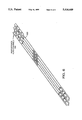
- FIG. 4 illustrates a plurality of video tracks and audio channels, as ideally written on a magnetic tape, and is useful in illustrating the principles of our invention
- FIG. 5 illustrates a plurality of video tracks and audio channels, as written on a magnetic tape like in FIG. 4 except that the video tracks are misaligned, and is useful in illustrating the principles of our invention
- FIG. 6 illustrates a plurality of video tracks and audio channels, as written on a magnetic tape like in FIG. 4 except that some of the audio channels are misaligned, and is useful in illustrating the principles of our invention.
- the illustrative embodiment is described in terms of video signals and audio signals being the subject of an edit optimization, that is also only by way of illustration, and not by way of limitation, for the information could be video signals, audio signals, both, or still another type of signal and further could be digital information, or analog information, or both, or still another form of information.
- an edit operator, or user, of the edit optimization system and method to be described could mount the storage medium such as the magnetic tape to be edited onto any of a variety of recorders for that storage medium such as the VPR® 300, which is a D2 composite digital format video tape recorder manufactured by Ampex Corporation, for a magnetic tape storage medium.
- the D2 composite digital format is a well known video tape format.
- the tape recorder which is to be used in the edit session may be different than the tape recorder that was used to store the information on the tape to be edited, or even the temperature and humidity between recording time and edit time may be different, it being noted that there is an almost limitless number of variables which could have an effect on the edit optimization process, where the edit optimization process includes the process of locating the precise location of the information to be edited in the edit session.
- the edit optimization function occurs before, and typically in anticipation of, the actual edit function, for example, before an insert edit function.
- the edit optimization function can be thought of as involving a process of preparing or initializing the tape recorder in which the tape and heads are aligned and, using the principles of our invention, are automatically aligned so that an optimal edit function can thereafter take place.
- FIGS. 4, 5 and 6 each of which illustrates a magnetic tape 400 with four D2 formatted helical video tracks 410-1, 410-2, 410-3 and 410-4 recorded thereon.
- the well known D2 format also records four channels of digital audio information, which are labelled A1, A2, A3 and A4 and which are recorded at the ends of the helical video tracks 410-1, 410-2, 410-3 and 410-4.
- Each audio channel is actually recorded twice with identical data being written on the tape at alternate ends of adjacent video tracks to improve the protection of the written information against corrupted data caused, for example, by dropouts due to longitudinal scratching of the tape or format and interchange errors as well as to improve edit performance. Also, individual editing of the plurality of audio channels or the plurality of video channels is made easier by the D2 format including "edit gaps" such as gaps 420 or 421 between blocks of data stored on the individual tracks of the magnetic tape 400.
- an ideally optimized magnetic tape would insert the new video track(s) in perfect alignment with respect to the audio channels such as is illustrated in FIG. 4.
- the ideal does not always exist so we can plan for a "misoptimized" magnetic tape.
- a misoptimized magnetic tape consider a magnetic tape which could have inserted on it new, but mispositioned, video tracks such as mispositioned video tracks 540 shown in FIG. 5. Note that video tracks 540 are imperfectly aligned with respect to the audio channels also shown in FIG. 5. Note also that not only can newly inserted mispositioned video tracks 540 (versus ideally aligned tracks 410-3 and 410-4 shown in FIG.
- mispositioned video tracks 540 may partially overwrite some of the audio channels A1, A2, A3 or A4. For example, observe closely at point 530 how the ends of mispositioned video tracks 540 are illustrated in FIG. 5 as overwriting some of audio channels A2 and A4.
- mispositioned audio channels 660 As another example of a misoptimized magnetic tape, consider a magnetic tape which could have inserted on it new, but mispositioned, audio channels such as mispositioned audio channels 660 shown in FIG. 6. Note that audio channels 660 are imperfectly aligned with respect to the video tracks also shown in FIG. 6. Note also that not only can newly inserted audio channels 660 (versus the ideally aligned audio channels A1, A2, A3 and A4 of FIG. 4) be misaligned with respect to the video tracks 410-1, 410-2, 410-3 and 410-4 but the newly inserted audio channels may partially overwrite some of the video tracks. For example, observe closely at point 650 how the ends of mispositioned audio channels 660 are illustrated in FIG. 6 as overwriting some of video track 410-3.
- the center of a previously recorded track on the tape to be edited is found by identifying amplitude variations of a first nature, e.g., by varying the location of the record head with respect to a track on the magnetic tape (also known as “tracking” in the art) and concurrently detecting a peak amplitude signal that is read, or played back, through the record head (also known as "peaking" in the art).
- playback rf signal amplitude changes of a second nature are also caused by changes in the frequency spectrum due to variations in the recorded data patterns.
- amplitude variations of this second nature are identified and removed from the peak tracking amplitude computation.
- a detection is made of a playback rf output being provided from an automatic scan tracking playback head in order to derive a signal indicative of changes in the playback head output due only to data pattern variations.
- the playback head rf amplitude Prior to a playback rf output also being provided from a record head, the playback head rf amplitude is spectrally shaped to match it to that of the record head so that the difference signal is not affected by specific head properties and/or variations in characteristics such as head gap lengths.
- the amplitude variation due to data pattern variations alone is computed, and a correction signal corresponding to the inverse of the variation is fed back to normalize the gain of the record head amplifier in the record channel.
- the signal that is derived from the record head amplifier is due to the effects of tracking alone and can be used to provide precise positioning of the record head prior to the edit.
- an automatic scan tracking playback head 112 reads a magnetic tape 110, which can be like magnetic tape 400 shown in FIGS. 4, 5 and 6, and supplies a playback signal, via a cable 114, to a playback amplifier 116 having a fixed gain circuit 118. See, for example, U.S. Pat. No. 4,151,570 issued Apr. 24, 1979 for more information about automatic scan tracking.
- An output of the amplifier 116 is supplied to a head switch 120 via a cable 134. Switching of the head switch 120 is provided by means of a head switch control signal which corresponds to the video vertical rate signal and which is provided on a control cable 122.
- a record head 124 supplies a playback signal to a variable gain amplifier 128 via a mode switch 126.
- the mode switch 126 includes a record mode contact and an edit play mode contact, with the edit play mode contact being coupled to the variable gain amplifier 128.
- the record contact is coupled to the output of a conventional record amplifier 127 which supplies the record head 124 with a video record signal via a cable 129, for example, as when performing an insert edit function after the edit optimization function has been completed.
- An output of the variable gain amplifier 128 is supplied to the head switch 120 via a cable 136.
- An output of the head switch 120 is coupled to a low pass filter 132, and thence to a linear detector circuit, which may be any of various linear detectors such as an average value detector, a root mean squared (RMS) detector or a peak level detector 130, such as is illustrated here.
- the cutoff frequency of the low pass filter 132 is selected to make the frequency response of the playback head channel match the frequency response of the record head channel. Thus, any difference between the output signals from the heads is not due to differences in the head properties or head characteristics.
- the input to the peak level detector 130 is either the amplified and filtered signal from the playback head 112 or the amplified and filtered signal from the record head 124, depending upon which position the head switch 120 is switched to via the vertical rate control signal on control cable 122.
- An output of peak level detector 130 comprises a pair of signals corresponding to the peak rf amplitudes of the playback head 112 and of the record head 124, which are coupled via a cable 140 to an analog-to-digital (A/D) converter 138, and thence to a suitably programmed microprocessor 142 via a cable 144.
- A/D analog-to-digital
- the microprocessor 142 manipulates the two peak rf amplitudes to provide a correction signal corresponding to the inverse of the difference between the two peak rf amplitudes.
- the correction signal 146 which is a measure of pattern sensitivity, is supplied to the variable gain amplifier 128 via a cable 146 and a digital-to-analog (D/A) converter 148 to vary the gain of the amplifier 128 and to thereby remove the effects of the pattern sensitivity.
- D/A converter 148 digital-to-analog
- longitudinal control track head 170 can read control track position signals from the magnetic tape in accord with the D2 format and extend those signals through control track playback circuits 175 for providing longitudinal position information to microprocessor 142.
- an automatic scan tracking playback head 212 reads a magnetic tape 210, which can be like magnetic tape 400 shown in FIGS. 4, 5 and 6 or magnetic tape 110 shown in FIG. 1, and supplies a playback signal through a low pass filter 232 to a variable gain playback amplifier 216.
- the cutoff frequency of low pass filter 232 is selected to make the frequency response of the first, or playback head, channel match the frequency response of the second, or record head, channel, which is later described. Thus, any difference between the output signals from the heads is not due to differences in the head properties or head characteristics.
- An output of the variable gain amplifier 216 is supplied to a linear detector circuit, which may be any of various linear detectors such as an average value detector, a root mean squared (RMS) detector or a peak level detector 230, such as is illustrated here.
- An output of peak level detector 230 comprises a signal corresponding to the peak rf amplitude of the playback head 212, which is coupled via a cable 240 to an A/D converter 238, and thence over cable 282 through a track sample memory 260 to a suitably programmed microprocessor 242 over cable 292.
- a record head 224 supplies a playback signal to a low pass filter 252 via a mode switch 226.
- the mode switch 226 includes a record mode contact and an edit play mode contact, with the edit play mode contact being coupled to the low pass filter 252.
- the record contact is coupled to the output of a conventional record amplifier 227 which supplies the record head 224 with a video record signal via a cable 229, for example, as when performing an edit function after the edit optimization function is complete.
- An output from low pass filter 252 is coupled to an input of variable gain amplifier 228.
- variable gain amplifier 228 is supplied to another linear detector circuit, which may be any of various linear detectors such as an average value detector, a root mean squared (RMS) detector or a peak level detector 250, such as is illustrated here.
- An output of peak level detector 250 comprises a signal corresponding to the peak rf amplitude of the record head 224, which is coupled via a cable 255 to an A/D converter 258, and thence over cable 284 through track sample memory 265 to a suitably programmed microprocessor 242 over cable 294.
- the first channel including peak level detector 230, A/D converter 238, and track sample memory 260 provides a first rf amplitude signal to the microprocessor 242 while the second channel including peak level detector 250, A/D converter 258, and track sample memory 265 provides a second rf amplitude signal to the microprocessor 242.
- the microprocessor 242 manipulates the two peak rf amplitudes to provide appropriate correction signals respectively to variable gain amplifiers 216 and 228, thereby, responsive to the two correction signals, obtaining a separate, independent and distinct gain control in each of the two channels.
- the track sample memories 260 and 265 are responsive to head switch signals, scanner tach signals, and timing signals (here illustratively a four MHz timing signal) provided over cable 280 to control logic 270, for storing and multiplexing the respective rf amplitude signals to microprocessor 242.
- the rf signals generated in the first channel can be used to adjust the gain control of amplifier 216 of the first channel and can also be used to normalize the record head rf amplitude signals with the playback head rf amplitude signals by adjusting the gain control of amplifier 228 in the second channel.
- the rf signals generated in the second channel can be used to adjust the tracking of the record head 224, for example, by automatically positioning tape 210 with respect to helical record head 224, all in response to the control signals from microprocessor 242, and to thereby perform an edit optimize that subsequently precisely locates the record head with respect to a track of the storage medium during an edit process.
- a longitudinal control track head 271 can read control track position signals from the magnetic tape in accordance with the D2 format and extend those signals through control track playback circuits 275 for providing longitudinal position information to microprocessor 242.
- the respective sample memories can be substantially identical for processing the respective first and the second rf amplitude signals. Therefore, the following discussion can be limited to one track sample memory, recognizing that the other track sample memory is substantially identical. However, before the detailed description of those elements a brief incite into the sampling philosophy and theory appears to be in order.
- Tape recorders using the D2 format typically include four record heads and four playback heads, which are grouped in pairs for reading and writing four tracks of magnetic tape. Typically each pair is electrically situated so that a playback head can read a track before the record head writes that same track. Sometimes such an arrangement is called "read before write” in the art. Typically there is a delay circuit in a read-before-write recorder so that the track that is read can be processed by the recorder in some designed manner before it is written, sometimes rewritten with old data and sometimes written with new data. For our purposes, on the one hand, edit optimization is more concerned with the location of the data on the storage medium and less concerned about the content of the stored information.
- the insert edit function which typically occurs after the edit optimization, is typically more concerned about the content of the information to be written on the storage medium and less concerned about the location on the storage medium at which the information will be written. This makes sense when it is recognized that the edit optimization function occurs first and is useful in the process of identifying where the insert edit function will later write the information.
- the edit optimization function can occur more precisely because the sampling rate of the storage medium is increased. This makes sense when it is recognized that a higher sampling rate can result in more data points being made available to be processed in determining a more precise location on the storage medium. Further, the edit optimization function can occur more precisely because each pair of playback and record heads reads the same track. Fortuitously, with the two channel approach now being discussed not only are four tracks of magnetic tape being read but two heads on each track do the reading, all at a faster sampling rate. The data thusly generated can be processed by microprocessor 242 to provide more precise correction signals to more precisely locate the tracks on the tape and to more precisely position the heads over the tracks, which greatly improves the edit optimization function.
- a scanner tach signal may be provided by scanner circuitry, which is not part of the present invention, as a reference sampling signal.
- each track on the magnetic tape can include a plurality of blocks of video information where each block includes a video track and two audio channels which are recorded twice with identical data being written on the tape at alternate ends of adjacent video tracks. Responsive to the reference sampling signal, each block on a track may be sampled eight times--one time for each of the two leading audio channels, four times for the video track, and one time for each of the two trailing audio channels. Note that this emphasizes again the large amount of data that can be collected to more precisely perform an edit optimize.
- each video block is sampled eight times by each of that track's playback head and record head, which gives rise to 16 samples per block, which in turn gives rise to 64 samples across the width of the four tracks of one scanner.
- the video track and the audio channels are sampled separately and accordingly the data samples may be processed independently by microprocessor 242.
- mispositioned video tracks and mispositioned audio channels can be processed independently and optimized independently, as required, for example, using the read before write process, which was discussed earlier.
- a track can, if desired, be rewritten in its entirety or some segments of the track can be rewritten and other segments left intact, etc. Choices can be displayed to the operator on a display panel and selections may be made by the operator--all these increased possibilities flowing from the more precise edit optimization that is possible in accordance with the principles of our invention.
- Head switch signals, scanner tach signals, and a four MHz timing signal can be provided by other recorder circuitry, which is not part of the invention, over cable 280 to control logic 270 and therein through counter 301 to control PROM 302.
- PROM 302 signals over cable 272 Responsive to PROM 302 signals over cable 272, the respective first rf amplitude signals from the respective four playback heads, as provided over cable 282, are stored in playback head sample stores 310, 311, 312 and 313 of track sample memory 260. Thereafter and responsive to enable signals over cable 292 from microprocessor 242 to multiplexors 320 and 321, the first respective rf amplitude signals can be provided from the respective sample stores over cable 293 to the microprocessor for edit optimization processing.
- the respective second rf amplitude signals from the respective four record heads, as provided over cable 284, are stored in record head sample stores 330, 331, 332 and 333 of track sample memory 265. Thereafter and responsive to enable signals over cable 294 from microprocessor 242 to multiplexors 340 and 341, the second respective rf amplitude signals can be provided from the respective sample stores over cable 293 to the microprocessor for edit optimization processing.
- Microprocessor 242 can be suitably programmed to perform the edit optimization function.
- Appendix A includes a source code listing in the C++ programming language for performing the sampling of the rf amplitude signals and for removing the pattern sensitivity.
- Appendix B includes a source code listing in the C++ programming language for reading the processed data from the program represented by the code in Appendix A and for performing the edit optimization and for providing the correction signals to variable gain amplifiers 216 and 228.
Abstract
Description
Claims (21)
Priority Applications (1)
| Application Number | Priority Date | Filing Date | Title |
|---|---|---|---|
| US08/272,443 US5416649A (en) | 1991-04-12 | 1994-07-08 | Single channel method and apparatus for automatically optimizing insert editing in a signal recorder |
Applications Claiming Priority (2)
| Application Number | Priority Date | Filing Date | Title |
|---|---|---|---|
| US68526291A | 1991-04-12 | 1991-04-12 | |
| US08/272,443 US5416649A (en) | 1991-04-12 | 1994-07-08 | Single channel method and apparatus for automatically optimizing insert editing in a signal recorder |
Related Parent Applications (1)
| Application Number | Title | Priority Date | Filing Date |
|---|---|---|---|
| US68526291A Continuation | 1991-04-12 | 1991-04-12 |
Publications (1)
| Publication Number | Publication Date |
|---|---|
| US5416649A true US5416649A (en) | 1995-05-16 |
Family
ID=24751430
Family Applications (1)
| Application Number | Title | Priority Date | Filing Date |
|---|---|---|---|
| US08/272,443 Expired - Lifetime US5416649A (en) | 1991-04-12 | 1994-07-08 | Single channel method and apparatus for automatically optimizing insert editing in a signal recorder |
Country Status (2)
| Country | Link |
|---|---|
| US (1) | US5416649A (en) |
| KR (1) | KR920020488A (en) |
Cited By (2)
| Publication number | Priority date | Publication date | Assignee | Title |
|---|---|---|---|---|
| US5982975A (en) * | 1996-06-28 | 1999-11-09 | Samsung Electronics Co., Ltd. | Video signal copying apparatus |
| US6101312A (en) * | 1995-06-06 | 2000-08-08 | Sharp Kabushiki Kaisha | Automatic picture quality controller |
Citations (21)
| Publication number | Priority date | Publication date | Assignee | Title |
|---|---|---|---|---|
| US4151570A (en) * | 1976-03-22 | 1979-04-24 | Ampex Corporation | Automatic scan tracking using a magnetic head supported by a piezoelectric bender element |
| JPS5525876A (en) * | 1978-08-16 | 1980-02-23 | Hitachi Ltd | Magnetic recording reproducer |
| US4347534A (en) * | 1980-01-18 | 1982-08-31 | Olympus Optical Co., Ltd. | Auto-tracking system for magnetic tape recording device |
| EP0094207A2 (en) * | 1982-05-07 | 1983-11-16 | Matsushita Electric Industrial Co., Ltd. | Video tape recorder having uninterrupted tracking control during insert edit mode |
| EP0095766A1 (en) * | 1982-05-31 | 1983-12-07 | Hitachi, Ltd. | Servo circuit for a signal reproducing apparatus |
| US4422108A (en) * | 1978-08-16 | 1983-12-20 | Hitachi, Ltd. | Tape recorder |
| US4486796A (en) * | 1980-11-12 | 1984-12-04 | Sony Corporation | Apparatus and method for controlling the position of a rotary head |
| US4488185A (en) * | 1981-07-22 | 1984-12-11 | Tokyo Shibaura Denki Kabushiki Kaisha | Assemble editing system for video tape recorder |
| US4504870A (en) * | 1981-07-23 | 1985-03-12 | Victor Company Of Japan, Ltd. | Automatic level adjustment with means for minimizing drop-out effects |
| JPS6079550A (en) * | 1983-06-02 | 1985-05-07 | Mitsubishi Electric Corp | Magnetic recording and reproducing device |
| US4520410A (en) * | 1982-02-26 | 1985-05-28 | Nippon Electric Co., Ltd. | Scan tracking apparatus for helical scan video tape recorder |
| JPS61284853A (en) * | 1985-06-10 | 1986-12-15 | Sony Corp | Video signal recording device |
| US4689706A (en) * | 1982-09-15 | 1987-08-25 | Ampex Corporation | Apparatus and method for adjusting the respective positions of a magnetic head and video information along a magnetic track |
| WO1987006048A1 (en) * | 1986-03-24 | 1987-10-08 | Ampex Corporation | Magnetically controlled scanning magnetic head tracking control system |
| US4745496A (en) * | 1982-09-15 | 1988-05-17 | Ampex Corporation | Apparatus and method for adjusting the tracking position of a magnetic head along a magnetic track |
| JPS6410409A (en) * | 1987-07-01 | 1989-01-13 | Matsushita Electric Ind Co Ltd | Magnetic recording and reproducing device |
| US4901166A (en) * | 1986-03-20 | 1990-02-13 | Sony Corporation | Tracking control for VTR editing employing previously recorded tracking information |
| US4977469A (en) * | 1987-03-30 | 1990-12-11 | Pioneer Electronic Corporation | Signal reproducing device which offsets the tracking error signal |
| US5077623A (en) * | 1990-03-30 | 1991-12-31 | Ampex Corporation | Method and apparatus for automatically optimizing the record current in a tape recorder using a reference tape |
| US5107381A (en) * | 1987-08-04 | 1992-04-21 | Mitsubishi Denki Kabushiki Kaisha | Automatic tracking control for magnetic recording and/or reproducing apparatus with reference phase setting capability |
| US5130859A (en) * | 1989-04-28 | 1992-07-14 | Sony Corporation | Videotape recorder |
-
1992
- 1992-04-10 KR KR1019920006015A patent/KR920020488A/en not_active Application Discontinuation
-
1994
- 1994-07-08 US US08/272,443 patent/US5416649A/en not_active Expired - Lifetime
Patent Citations (23)
| Publication number | Priority date | Publication date | Assignee | Title |
|---|---|---|---|---|
| US4151570A (en) * | 1976-03-22 | 1979-04-24 | Ampex Corporation | Automatic scan tracking using a magnetic head supported by a piezoelectric bender element |
| JPS5525876A (en) * | 1978-08-16 | 1980-02-23 | Hitachi Ltd | Magnetic recording reproducer |
| US4422108A (en) * | 1978-08-16 | 1983-12-20 | Hitachi, Ltd. | Tape recorder |
| US4347534A (en) * | 1980-01-18 | 1982-08-31 | Olympus Optical Co., Ltd. | Auto-tracking system for magnetic tape recording device |
| US4486796A (en) * | 1980-11-12 | 1984-12-04 | Sony Corporation | Apparatus and method for controlling the position of a rotary head |
| US4488185A (en) * | 1981-07-22 | 1984-12-11 | Tokyo Shibaura Denki Kabushiki Kaisha | Assemble editing system for video tape recorder |
| US4504870A (en) * | 1981-07-23 | 1985-03-12 | Victor Company Of Japan, Ltd. | Automatic level adjustment with means for minimizing drop-out effects |
| US4520410A (en) * | 1982-02-26 | 1985-05-28 | Nippon Electric Co., Ltd. | Scan tracking apparatus for helical scan video tape recorder |
| US4602298A (en) * | 1982-05-07 | 1986-07-22 | Matsushita Electric Industrial Co., Ltd. | Video tape recorder having uninterrupted tracking control during insert edit mode |
| EP0094207A2 (en) * | 1982-05-07 | 1983-11-16 | Matsushita Electric Industrial Co., Ltd. | Video tape recorder having uninterrupted tracking control during insert edit mode |
| EP0095766A1 (en) * | 1982-05-31 | 1983-12-07 | Hitachi, Ltd. | Servo circuit for a signal reproducing apparatus |
| EP0299542A2 (en) * | 1982-09-15 | 1989-01-18 | Ampex Corporation | Apparatus and method for adjusting the tracking of a video recorder |
| US4689706A (en) * | 1982-09-15 | 1987-08-25 | Ampex Corporation | Apparatus and method for adjusting the respective positions of a magnetic head and video information along a magnetic track |
| US4745496A (en) * | 1982-09-15 | 1988-05-17 | Ampex Corporation | Apparatus and method for adjusting the tracking position of a magnetic head along a magnetic track |
| JPS6079550A (en) * | 1983-06-02 | 1985-05-07 | Mitsubishi Electric Corp | Magnetic recording and reproducing device |
| JPS61284853A (en) * | 1985-06-10 | 1986-12-15 | Sony Corp | Video signal recording device |
| US4901166A (en) * | 1986-03-20 | 1990-02-13 | Sony Corporation | Tracking control for VTR editing employing previously recorded tracking information |
| WO1987006048A1 (en) * | 1986-03-24 | 1987-10-08 | Ampex Corporation | Magnetically controlled scanning magnetic head tracking control system |
| US4977469A (en) * | 1987-03-30 | 1990-12-11 | Pioneer Electronic Corporation | Signal reproducing device which offsets the tracking error signal |
| JPS6410409A (en) * | 1987-07-01 | 1989-01-13 | Matsushita Electric Ind Co Ltd | Magnetic recording and reproducing device |
| US5107381A (en) * | 1987-08-04 | 1992-04-21 | Mitsubishi Denki Kabushiki Kaisha | Automatic tracking control for magnetic recording and/or reproducing apparatus with reference phase setting capability |
| US5130859A (en) * | 1989-04-28 | 1992-07-14 | Sony Corporation | Videotape recorder |
| US5077623A (en) * | 1990-03-30 | 1991-12-31 | Ampex Corporation | Method and apparatus for automatically optimizing the record current in a tape recorder using a reference tape |
Non-Patent Citations (4)
| Title |
|---|
| Azuma et al, "Microprocessor Controlled Variable Play-back Speed System for Video Tape Recorder" IEEE Transactions on Consumer Electronics, vol. CE-26, No. 1, pp. 121-128 Feb. 1980. |
| Azuma et al, Microprocessor Controlled Variable Play back Speed System for Video Tape Recorder IEEE Transactions on Consumer Electronics, vol. CE 26, No. 1, pp. 121 128 Feb. 1980. * |
| VPR 300 Series, Video Production Recorder Service Manual, vol. II, Catalog 1520528 02 (Aug., 1989) pp. 6 192 6 199. * |
| VPR-300 Series, Video Production Recorder Service Manual, vol. II, Catalog #1520528-02 (Aug., 1989) pp. 6-192-6-199. |
Cited By (2)
| Publication number | Priority date | Publication date | Assignee | Title |
|---|---|---|---|---|
| US6101312A (en) * | 1995-06-06 | 2000-08-08 | Sharp Kabushiki Kaisha | Automatic picture quality controller |
| US5982975A (en) * | 1996-06-28 | 1999-11-09 | Samsung Electronics Co., Ltd. | Video signal copying apparatus |
Also Published As
| Publication number | Publication date |
|---|---|
| KR920020488A (en) | 1992-11-21 |
Similar Documents
| Publication | Publication Date | Title |
|---|---|---|
| US4249218A (en) | Method and apparatus for editing digitally recorded audio signals | |
| CA1187603A (en) | Apparatus and method for controlling the position of a rotary head | |
| US20030099057A1 (en) | Hybrid servopositioning systems | |
| EP0030300B1 (en) | Magnetic data recorder circuit and method of operating magnetic data recorders | |
| US5077623A (en) | Method and apparatus for automatically optimizing the record current in a tape recorder using a reference tape | |
| JP2933364B2 (en) | Method and apparatus for selecting a threshold voltage for determining whether data written on a magnetic recording tape in a tape drive has sufficient amplitude | |
| US5420731A (en) | Two channel method and apparatus for automatically optimizing insert editing in a signal recorder | |
| US5088077A (en) | Synchronization of record media transports and tracking adjustment | |
| US5416649A (en) | Single channel method and apparatus for automatically optimizing insert editing in a signal recorder | |
| EP0508510A2 (en) | Method and apparatus for automatically optimizing insert editing in a signal recorder | |
| JP2818287B2 (en) | Track following control method for magnetic tape recorder | |
| US4638378A (en) | Fidelity control during operation of duplicator machines | |
| JP2768759B2 (en) | Information recording and playback method | |
| US5737146A (en) | Data recording and playback apparatus using a helical scan system with magnetic head for recording and playing back pattern signal for tracking in tracking area within helical track | |
| US4542425A (en) | Apparatus for reading a record carrier | |
| JP2644594B2 (en) | Tracking control method | |
| JP2646997B2 (en) | Tape speed measurement method | |
| JPS59127277A (en) | Tracking control circuit of information signal reproducing device | |
| EP0788092A1 (en) | Record head alignment for a helical scan recorder using play head information | |
| JPS63104254A (en) | Magnetic picture recording and reproducing device | |
| JPH07130143A (en) | Magnetic recording and reproducing device | |
| JPS63288450A (en) | Method for adjusting atf gain of rotary head type tape recorder | |
| JPS58100255A (en) | Tape speed discriminating method of magnetic recording and reproducing device | |
| JPS6376139A (en) | Rotary head type digital audio reproducing device | |
| JPH03292661A (en) | Adjusting device for magnetic recording and reproducing device |
Legal Events
| Date | Code | Title | Description |
|---|---|---|---|
| AS | Assignment |
Owner name: AMPEX CORPORATION, CALIFORNIA Free format text: ASSIGNMENT OF ASSIGNORS INTEREST;ASSIGNOR:AMPEX SYSTEMS CORPORATION, A DE CORPORATION;REEL/FRAME:007456/0224 Effective date: 19950426 |
|
| STCF | Information on status: patent grant |
Free format text: PATENTED CASE |
|
| FEPP | Fee payment procedure |
Free format text: PAYOR NUMBER ASSIGNED (ORIGINAL EVENT CODE: ASPN); ENTITY STATUS OF PATENT OWNER: LARGE ENTITY |
|
| FPAY | Fee payment |
Year of fee payment: 4 |
|
| FEPP | Fee payment procedure |
Free format text: PAT HOLDER CLAIMS SMALL ENTITY STATUS, ENTITY STATUS SET TO SMALL (ORIGINAL EVENT CODE: LTOS); ENTITY STATUS OF PATENT OWNER: LARGE ENTITY |
|
| FPAY | Fee payment |
Year of fee payment: 8 |
|
| FEPP | Fee payment procedure |
Free format text: PAT HOLDER NO LONGER CLAIMS SMALL ENTITY STATUS, ENTITY STATUS SET TO UNDISCOUNTED (ORIGINAL EVENT CODE: STOL); ENTITY STATUS OF PATENT OWNER: LARGE ENTITY |
|
| REFU | Refund |
Free format text: REFUND - PAYMENT OF MAINTENANCE FEE, 12TH YR, SMALL ENTITY (ORIGINAL EVENT CODE: R2553); ENTITY STATUS OF PATENT OWNER: LARGE ENTITY |
|
| FPAY | Fee payment |
Year of fee payment: 12 |
|
| AS | Assignment |
Owner name: HILLSIDE CAPITAL INCORPORATED, NEW YORK Free format text: SECURITY AGREEMENT;ASSIGNOR:AMPEX CORPORATION;REEL/FRAME:021630/0230 Effective date: 20081003 |