US5504643A - Magnetic read/write head having a writing-compensated magnetoresistant element - Google Patents
Magnetic read/write head having a writing-compensated magnetoresistant element Download PDFInfo
- Publication number
- US5504643A US5504643A US08/297,815 US29781594A US5504643A US 5504643 A US5504643 A US 5504643A US 29781594 A US29781594 A US 29781594A US 5504643 A US5504643 A US 5504643A
- Authority
- US
- United States
- Prior art keywords
- magnetic
- magnetic circuit
- magnetoresistant
- writing
- conductor
- Prior art date
- Legal status (The legal status is an assumption and is not a legal conclusion. Google has not performed a legal analysis and makes no representation as to the accuracy of the status listed.)
- Expired - Fee Related
Links
- 239000004020 conductor Substances 0.000 claims abstract description 40
- 238000000034 method Methods 0.000 claims description 9
- 230000001939 inductive effect Effects 0.000 claims description 5
- 230000005465 channeling Effects 0.000 claims 1
- 125000006850 spacer group Chemical group 0.000 description 7
- RYGMFSIKBFXOCR-UHFFFAOYSA-N Copper Chemical compound [Cu] RYGMFSIKBFXOCR-UHFFFAOYSA-N 0.000 description 5
- 229910052802 copper Inorganic materials 0.000 description 5
- 239000010949 copper Substances 0.000 description 5
- 238000000151 deposition Methods 0.000 description 4
- 230000008021 deposition Effects 0.000 description 4
- 238000005530 etching Methods 0.000 description 4
- 238000000206 photolithography Methods 0.000 description 4
- 239000000758 substrate Substances 0.000 description 4
- 238000004804 winding Methods 0.000 description 4
- VYPSYNLAJGMNEJ-UHFFFAOYSA-N Silicium dioxide Chemical compound O=[Si]=O VYPSYNLAJGMNEJ-UHFFFAOYSA-N 0.000 description 3
- 230000006698 induction Effects 0.000 description 3
- 238000004544 sputter deposition Methods 0.000 description 3
- UGKDIUIOSMUOAW-UHFFFAOYSA-N iron nickel Chemical compound [Fe].[Ni] UGKDIUIOSMUOAW-UHFFFAOYSA-N 0.000 description 2
- 230000005415 magnetization Effects 0.000 description 2
- 239000004065 semiconductor Substances 0.000 description 2
- 229910052710 silicon Inorganic materials 0.000 description 2
- 239000010703 silicon Substances 0.000 description 2
- 230000015572 biosynthetic process Effects 0.000 description 1
- 238000005868 electrolysis reaction Methods 0.000 description 1
- 238000005516 engineering process Methods 0.000 description 1
- 238000004519 manufacturing process Methods 0.000 description 1
- 238000005259 measurement Methods 0.000 description 1
- 238000001259 photo etching Methods 0.000 description 1
- 230000000284 resting effect Effects 0.000 description 1
Images


Classifications
-
- G—PHYSICS
- G11—INFORMATION STORAGE
- G11B—INFORMATION STORAGE BASED ON RELATIVE MOVEMENT BETWEEN RECORD CARRIER AND TRANSDUCER
- G11B5/00—Recording by magnetisation or demagnetisation of a record carrier; Reproducing by magnetic means; Record carriers therefor
- G11B5/127—Structure or manufacture of heads, e.g. inductive
- G11B5/33—Structure or manufacture of flux-sensitive heads, i.e. for reproduction only; Combination of such heads with means for recording or erasing only
- G11B5/39—Structure or manufacture of flux-sensitive heads, i.e. for reproduction only; Combination of such heads with means for recording or erasing only using magneto-resistive devices or effects
- G11B5/3903—Structure or manufacture of flux-sensitive heads, i.e. for reproduction only; Combination of such heads with means for recording or erasing only using magneto-resistive devices or effects using magnetic thin film layers or their effects, the films being part of integrated structures
- G11B5/3967—Composite structural arrangements of transducers, e.g. inductive write and magnetoresistive read
Definitions
- the present invention relates to a magnetic read/write head having a writing-compensated magnetoresistant element. It is used in magnetic information recording.
- Magnetic read/write heads which use as the reading means a magnetoresistant element.
- the magnetoresistant element was placed in the head gap of the magnetic circuit of the head.
- the writing field produces in the magnetoresistant element a very high field, which saturates said element in the direction of the field. If it is then wished to use this head in reading, it is necessary to wait for the magnetic zones of the magnetoresistant layer to have returned precisely in the initial orientation appropriate for reading, i.e. in general 45° from the axis of the element.
- One solution to this problem consists of using two heads, one for writing and the other for reading and only the reading head has a magnetoresistant element.
- said element is never subject to high fields and therefore has an extremely stable zone structure.
- the invention does not adopt this solution and returns to heads having a single head gap, but in a particular, so-called horizontal structure with thin layers or films.
- heads are known and described in FR-A-2,645,314 (or the corresponding U.S. Pat. No. 5,208,716). A head of this type is described relative to the attached FIG. 1.
- FIG. 1 shows in section a horizontal head having a semiconductor substrate 10, e.g. of silicon, in which has been etched a recess 12.
- a lower magnetic layer 14 is electrolytically formed and is extended by two vertical posts 16 1 , 16 2 , which are surrounded by a conductor coil 18.
- This coil is embedded in an insulating layer 20.
- the magnetic circuit is completed by an upper pole piece subdivided into two parts 22 1 , 22 2 by an amagnetic spacer 24.
- a magnetoresistant element MR e.g. of iron-nickel is placed beneath the amagnetic spacer 24. This element can be obtained by photoetching using the spacer as the mask and is consequently self-aligned with respect to the spacer.
- the head moves in front of a magnetic support 30, where are recorded the informations to be read or written.
- the invention proposes placing beneath and in the vicinity of a magnetoresistant element, a conductor element traversed by the writing current. This current will create around it an additional magnetic field, which will pass through the magnetoresistant element. If the connection direction is correct, this additional field will oppose the writing leakage field. Therefore this additional field will act like a compensating field and will reduce or cancel out the overall magnetic field in the magnetoresistant element in the writing phase.
- the present invention consequently relates to a magnetic read/write head having a magnetic circuit with a head gap, a magnetoresistant element located beneath the head gap and a conductor coil surrounding part of the magnetic circuit, said coil being traversed by an electric current during a writing phase, said current creating a writing magnetic field in the magnetic circuit, part of said writing field, known as the leakage field, traversing the magnetoresistant element, said head being characterized in that it also comprises an electrical conductor element placed beneath the magnetoresistant element and connected in series with the conductor coil in a direction such that, in writing, the current flowing in said conductor element produces in the magnetoresistant element a magnetic field in the opposite direction to the leakage field passing through the magnetoresistant element.
- the head according to the invention comprises an additional magnetic layer connected to the magnetic circuit and having an opening positioned between the magnetoresistant element and the electrical conductor element.
- This additional layer makes it possible to optimize the efficiency of the head on reading.
- the opening of the thin magnetic layer or film has a width substantially equal to or smaller than the width of the magnetoresistant element.
- FIG. 1 already described, shows a magnetic head having a magnetoresistant element according to the prior art.
- FIG. 2 shows in section a magnetic head according to the invention.
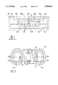
- FIG. 3 illustrates the electrical connection between the conductor element placed beneath the magnetoresistant element and the conductor coil.
- FIG. 4 diagrammatically shows the magnetic field lines in writing.
- FIG. 5 diagrammatically shows the magnetic field lines in reading.
- FIG. 6 shows a first subassembly along a first sectional plane passing through the centre of the coil.
- FIG. 7 shows a second subassembly along a second sectional plane passing through one of the connectors of the conductor element.
- FIG. 8 shows in section a third subassembly completed by the conductor element connected to the coil.
- FIG. 9 shows in section a fourth subassembly completed by the additional magnetic field.
- FIG. 10 shows in section a fifth subassembly incorporating the magnetoresistant element.
- FIG. 2 shows a magnetic read/write head according to the invention.
- the elements already shown in FIG. 1 carry the same references.
- the head also comprises a conductor element 40, e.g. of copper, connected to the coil 18 (as can best be seen in FIG. 3) and an additional magnetic layer 44 having an opening or head gap 46.
- the width of said opening is substantially equal to or smaller than that of the magnetoresistant element MR, but the width of the conductor element 40 is greater than that of said magnetoresistant element.
- the magnetic layer 44 can have a thickness between approximately 0.1 ⁇ m and approximately 5 ⁇ m.
- the conductor element 40 can be at a distance between approximately 0.1 and 1 ⁇ m from the magnetic layer 44.
- the upper magnetic layer of the magnetic circuit is formed from three double portions, one 32 1 , 32 2 being horizontal and in contact with the additional layer 44, another 34 1 , 34 2 , which is slightly inclined and freeing the additional layer 44 around its opening 46, and a third, which is once again horizontal, 36 1 , 36 2 on each side of the spacer 24.
- FIG. 3 shows in plan view a conductor coil 18 in double spiral form surrounding the two magnetic posts 16 1 , 16 2 .
- Two conductor elements 51,52 make it possible to connect the winding to any supply means.
- the coil 18 is terminated at two ends 53,54 located in the median plane of the head. These two ends lead to two connectors 55,56 making it possible to connect the conductor element 40.
- the writing current passing through the conductor or winding 18 consequently passes integrally into the conductor element 40.
- the connection direction thereof can be referred to as "in opposition", to the extent that the direction of the current in the element 40 is such that the additional magnetic field resulting therefrom above the element is in the opposite direction to the magnetic field channelled by the magnetic circuit and resulting from the flow of the current in the coil 18. Thus, it is under this condition that the additional magnetic field can compensate the leakage field upon writing.
- FIGS. 4 and 5 provide a better understanding of the head according to the invention.
- FIG. 4 corresponds to operation in writing. It is possible to see the writing field H1 channelled by the magnetic circuit, with a portion H2 constituting a leakage field, channelled by the additional layer 44 and straddling the opening 46 serving as the head gap.
- the field H3 resulting from the flow of the current in the element 40 (perpendicular to the plane of the drawing) is opposed to H2. The resultant is zero if the head is well dimensioned or, in any case, smaller than the field H2.
- FIG. 5 illustrates the operation of the head in reading.
- the field H4 is created by the information to be read. It is partly closed along field H5 by the magnetic circuit and partly by the field H6 channelled by the additional magnetic layer 44. As a result of the opening 46 serving as a head gap, said field H6 passes into the magnetoresistant element MR and gives access to the information read.
- FIGS. 6 to 10 illustrate different stages of a process for the production of the head described hereinbefore. Numerous operations have already been described in the aforementioned FR-A-2,645,314 (or the corresponding U.S. Pat. No. 5,208,716) and will consequently not be described again here. Only the operations specific to the realization of the conductor element and the additional magnetic layer will be described.
- the first stage is to produce on a semiconductor substrate 10, which is e.g. of silicon, a recess 12, a lower magnetic layer 14 and two magnetic posts 16 1 , 16 2 , as described in FR-A-2,645,314.
- a semiconductor substrate 10 which is e.g. of silicon
- a recess 12 e.g. of silicon
- a lower magnetic layer 14 e.g. of magnetic posts 16 1 , 16 2
- Two interconnections 47,49 are then formed through the substrate 10 and the lower magnetic layer, as well as two connectors 51,52, whose arrangement has been shown with respect to FIG. 3. Therefore FIG. 6 corresponds to a section along the line aa of FIG. 3, i.e. a section passing through connectors 51,52.
- FIG. 7 corresponds to a section along the line bb of FIG. 3, i.e. a section passing through the end 53 of the coil.
- an insulating layer 60 which can be approximately 2 ⁇ m thick silica (SiO 2 ). This is followed by photolithography and then reactive ionic etching in order to etch said layer perpendicular to the coil ends 53,54.
- two openings are grown, e.g. by electrolysis, connectors 55,56 (only the connector 55 being visible in the section of FIG. 7), said connectors being e.g. of copper.
- the copper deposit is then planarized so that the two connectors are flush with the surface of the insulating layer 60.
- FIG. 8 shows the conductor element in section at its end resting on the connector 55.
- the width of the conductor element 40 can be between approximately 1 and 15 ⁇ m, whilst its length can be approximately 3 to 15 ⁇ m.
- a thin insulating layer 62 e.g. of silica (SiO 2 ) can then be deposited on the assembly and cathodic sputtering can be used.
- the thickness of said layer can be approximately 0.05 to 3 ⁇ m, the layer covering the conductor element 40.
- an e.g. iron-nickel, magnetic layer 44 is followed by the deposition of an e.g. iron-nickel, magnetic layer 44. It is e.g. possible to use cathodic sputtering.
- the thickness of said layer can be between approximately 0.1 and 5 ⁇ m.
- an opening 46 is made in the centre of the magnetic layer 44.
- the width of said opening is approximately the same or smaller than that of the future magnetoresistant element and can e.g. be approximately 1 to 6 ⁇ m.
- an insulating layer 70 (FIG. 10), which is e.g. of silica (SiO 2 ). Its thickness is between approximately 0.1 and 1 ⁇ m. Then, using any known process, the magnetoresistant element MR is deposited.
- An insulating layer 72 is deposited on the magnetoresistant element in order to electrically insulate it. Two interconnections are then made through the substrate 10 in order to obtain two output elements permitting the measurement of the reading voltage.
- the addition, according to the invention, of the conductor element 40 and the magnetic layer 44 does not lead to any increase in the number of connectors compared with a head in accordance with FR-A-2,645,314. There are still four connectors (possibly even three if two are combined).
- the insulating layers 70,72 are etched above the magnetic posts, followed by the deposition of the magnetic layers 32 1 , 32 2 and 34 1 , 34 2 , already shown in FIG. 2.
- the spacer 24 is then formed by means described in the prior art and in particular in FR-A-2,645,314 and finally the pole pieces 36 1 , 36 2 are formed.
Abstract
Description
Claims (7)
Applications Claiming Priority (2)
| Application Number | Priority Date | Filing Date | Title |
|---|---|---|---|
| FR9310560A FR2709855B1 (en) | 1993-09-06 | 1993-09-06 | Magnetic read and write head with magnetoresistive element compensated for writing. |
| FR9310560 | 1993-09-06 |
Publications (1)
| Publication Number | Publication Date |
|---|---|
| US5504643A true US5504643A (en) | 1996-04-02 |
Family
ID=9450576
Family Applications (1)
| Application Number | Title | Priority Date | Filing Date |
|---|---|---|---|
| US08/297,815 Expired - Fee Related US5504643A (en) | 1993-09-06 | 1994-08-30 | Magnetic read/write head having a writing-compensated magnetoresistant element |
Country Status (5)
| Country | Link |
|---|---|
| US (1) | US5504643A (en) |
| EP (1) | EP0644528B1 (en) |
| JP (1) | JPH0798823A (en) |
| DE (1) | DE69416224T2 (en) |
| FR (1) | FR2709855B1 (en) |
Cited By (6)
| Publication number | Priority date | Publication date | Assignee | Title |
|---|---|---|---|---|
| US5764448A (en) * | 1993-11-08 | 1998-06-09 | Commissariat A L'energie Atomique | Magnetic read head having a multilayer magnetoresistant element and a concentrator, as well as its production process |
| US5821517A (en) * | 1994-12-02 | 1998-10-13 | Commissariata L'energie Atomique | Magnetic encoder for reading marks on an associated magnetic track |
| US5835313A (en) * | 1996-09-10 | 1998-11-10 | Alps Electric Co., Ltd. | Combination read/write thin film magnetic head |
| US6727537B2 (en) * | 2001-08-11 | 2004-04-27 | Hitachi, Ltd. | Magnetic memory cell |
| US7130152B1 (en) | 1999-04-01 | 2006-10-31 | Storage Technology Corporation | High track density magnetic recording head |
| DE10024332B4 (en) * | 1999-05-24 | 2006-12-21 | International Business Machines Corp. | Magnetic read / write head with electromagnetic field compensating element |
Citations (17)
| Publication number | Priority date | Publication date | Assignee | Title |
|---|---|---|---|---|
| US2975241A (en) * | 1956-12-12 | 1961-03-14 | Armour Res Found | Means for counteracting shunt reluctance of a transducer head gap |
| US3670114A (en) * | 1969-11-17 | 1972-06-13 | Mca Technology Inc | Electromagnetic transducer head having a bias frequency gap and an intelligence frequency gap |
| US4639289A (en) * | 1984-02-03 | 1987-01-27 | Commissariat A L'energie Atomique | Process for producing a magnetic read - write head and head obtained by this process |
| US4684438A (en) * | 1984-02-03 | 1987-08-04 | Commissariat A L'energie Atomique | Process for producing a coil for a magnetic recording head |
| US4689708A (en) * | 1985-08-02 | 1987-08-25 | Bbc Brown, Boveri & Co., Ltd. | Zone protective directional relay scheme |
| US4731157A (en) * | 1984-02-03 | 1988-03-15 | Commissariat A L'energie Atomique | Process for the production of a magnetic head for perpendicular recording |
| WO1988007741A1 (en) * | 1987-04-01 | 1988-10-06 | Digital Equipment Corporation | Magneto-resistive thin film head for digital magnetic storage device |
| US4809103A (en) * | 1984-02-03 | 1989-02-28 | Commissariat A L'energie Atomique | Head slider with an integrated flat magnetic head |
| US4837924A (en) * | 1986-09-17 | 1989-06-13 | Commissariat A L'energie Atomique | Process for the production of planar structure thin film magnetic heads |
| US4901177A (en) * | 1987-03-19 | 1990-02-13 | Commissariat A L'energie Atomique | Magnetic read head for a very narrow track |
| US5090111A (en) * | 1989-09-29 | 1992-02-25 | Commissariat A L'energie Atomique | Process for producing a magnetic recording head |
| EP0475397A2 (en) * | 1990-09-12 | 1992-03-18 | Sony Corporation | Planar thin film magnetic head |
| US5166849A (en) * | 1990-02-21 | 1992-11-24 | Commissariat A L'energie Atomique | Horizontal magnetic head with hall effect and its embodiment method |
| US5168408A (en) * | 1990-01-18 | 1992-12-01 | Commissariat A L'energie Atomique | Magnetic reading and writing head with magnetoresistant element |
| US5196976A (en) * | 1989-03-29 | 1993-03-23 | Commissariat A L'energie Atomique | Magnetoresistance magnetic head for perpendicular recording on a magnetic support |
| US5208716A (en) * | 1989-03-29 | 1993-05-04 | Commissariat A L'energie Atomique | Magnetoresistant magnetic head for longitudinal recording and process for producing such a head |
| US5274521A (en) * | 1990-08-23 | 1993-12-28 | Sony Corporation | Planar thin film magnetic head |
Family Cites Families (2)
| Publication number | Priority date | Publication date | Assignee | Title |
|---|---|---|---|---|
| JPS6049969B2 (en) * | 1977-07-05 | 1985-11-06 | 三菱電機株式会社 | signal regenerator |
| JPH0554341A (en) * | 1991-08-20 | 1993-03-05 | Sony Corp | Composite magnetic head |
-
1993
- 1993-09-06 FR FR9310560A patent/FR2709855B1/en not_active Expired - Fee Related
-
1994
- 1994-08-30 US US08/297,815 patent/US5504643A/en not_active Expired - Fee Related
- 1994-09-02 DE DE69416224T patent/DE69416224T2/en not_active Expired - Fee Related
- 1994-09-02 EP EP94401955A patent/EP0644528B1/en not_active Expired - Lifetime
- 1994-09-05 JP JP6234517A patent/JPH0798823A/en not_active Withdrawn
Patent Citations (19)
| Publication number | Priority date | Publication date | Assignee | Title |
|---|---|---|---|---|
| US2975241A (en) * | 1956-12-12 | 1961-03-14 | Armour Res Found | Means for counteracting shunt reluctance of a transducer head gap |
| US3670114A (en) * | 1969-11-17 | 1972-06-13 | Mca Technology Inc | Electromagnetic transducer head having a bias frequency gap and an intelligence frequency gap |
| US4639289A (en) * | 1984-02-03 | 1987-01-27 | Commissariat A L'energie Atomique | Process for producing a magnetic read - write head and head obtained by this process |
| US4684438A (en) * | 1984-02-03 | 1987-08-04 | Commissariat A L'energie Atomique | Process for producing a coil for a magnetic recording head |
| US4731157A (en) * | 1984-02-03 | 1988-03-15 | Commissariat A L'energie Atomique | Process for the production of a magnetic head for perpendicular recording |
| USRE33383E (en) * | 1984-02-03 | 1990-10-16 | Commissariat A L'energie Atomique | Process for producing a magnetic read write head and head obtained by this process |
| US4809103A (en) * | 1984-02-03 | 1989-02-28 | Commissariat A L'energie Atomique | Head slider with an integrated flat magnetic head |
| US4689708A (en) * | 1985-08-02 | 1987-08-25 | Bbc Brown, Boveri & Co., Ltd. | Zone protective directional relay scheme |
| US4837924A (en) * | 1986-09-17 | 1989-06-13 | Commissariat A L'energie Atomique | Process for the production of planar structure thin film magnetic heads |
| US4949207A (en) * | 1986-09-17 | 1990-08-14 | Commissariat A L'energie Atomique | Planar structure thin film magnetic head |
| US4901177A (en) * | 1987-03-19 | 1990-02-13 | Commissariat A L'energie Atomique | Magnetic read head for a very narrow track |
| WO1988007741A1 (en) * | 1987-04-01 | 1988-10-06 | Digital Equipment Corporation | Magneto-resistive thin film head for digital magnetic storage device |
| US5196976A (en) * | 1989-03-29 | 1993-03-23 | Commissariat A L'energie Atomique | Magnetoresistance magnetic head for perpendicular recording on a magnetic support |
| US5208716A (en) * | 1989-03-29 | 1993-05-04 | Commissariat A L'energie Atomique | Magnetoresistant magnetic head for longitudinal recording and process for producing such a head |
| US5090111A (en) * | 1989-09-29 | 1992-02-25 | Commissariat A L'energie Atomique | Process for producing a magnetic recording head |
| US5168408A (en) * | 1990-01-18 | 1992-12-01 | Commissariat A L'energie Atomique | Magnetic reading and writing head with magnetoresistant element |
| US5166849A (en) * | 1990-02-21 | 1992-11-24 | Commissariat A L'energie Atomique | Horizontal magnetic head with hall effect and its embodiment method |
| US5274521A (en) * | 1990-08-23 | 1993-12-28 | Sony Corporation | Planar thin film magnetic head |
| EP0475397A2 (en) * | 1990-09-12 | 1992-03-18 | Sony Corporation | Planar thin film magnetic head |
Cited By (6)
| Publication number | Priority date | Publication date | Assignee | Title |
|---|---|---|---|---|
| US5764448A (en) * | 1993-11-08 | 1998-06-09 | Commissariat A L'energie Atomique | Magnetic read head having a multilayer magnetoresistant element and a concentrator, as well as its production process |
| US5821517A (en) * | 1994-12-02 | 1998-10-13 | Commissariata L'energie Atomique | Magnetic encoder for reading marks on an associated magnetic track |
| US5835313A (en) * | 1996-09-10 | 1998-11-10 | Alps Electric Co., Ltd. | Combination read/write thin film magnetic head |
| US7130152B1 (en) | 1999-04-01 | 2006-10-31 | Storage Technology Corporation | High track density magnetic recording head |
| DE10024332B4 (en) * | 1999-05-24 | 2006-12-21 | International Business Machines Corp. | Magnetic read / write head with electromagnetic field compensating element |
| US6727537B2 (en) * | 2001-08-11 | 2004-04-27 | Hitachi, Ltd. | Magnetic memory cell |
Also Published As
| Publication number | Publication date |
|---|---|
| JPH0798823A (en) | 1995-04-11 |
| EP0644528A1 (en) | 1995-03-22 |
| DE69416224T2 (en) | 1999-07-29 |
| DE69416224D1 (en) | 1999-03-11 |
| EP0644528B1 (en) | 1999-01-27 |
| FR2709855A1 (en) | 1995-03-17 |
| FR2709855B1 (en) | 1995-10-20 |
Similar Documents
| Publication | Publication Date | Title |
|---|---|---|
| US5196976A (en) | Magnetoresistance magnetic head for perpendicular recording on a magnetic support | |
| US5703740A (en) | Toroidal thin film head | |
| US6027397A (en) | Dual element lapping guide system | |
| US5446613A (en) | Magnetic head assembly with MR sensor | |
| US6466402B1 (en) | Compact MR write structure | |
| EP0689196B1 (en) | Planar thin film magnetic head | |
| US4837924A (en) | Process for the production of planar structure thin film magnetic heads | |
| US6396660B1 (en) | Magnetic write element having a thermally dissipative structure | |
| US6362934B1 (en) | Highly aligned thin film tape head and method of making same | |
| US6609291B1 (en) | Method of manufacturing a thin film magnetic head | |
| US5809637A (en) | Method of making a magnetic head assembly with write pole/shield structure | |
| US6195232B1 (en) | Low-noise toroidal thin film head with solenoidal coil | |
| US5495378A (en) | Magnetoresistive sensor with improved performance and processability | |
| US5168408A (en) | Magnetic reading and writing head with magnetoresistant element | |
| US5208716A (en) | Magnetoresistant magnetic head for longitudinal recording and process for producing such a head | |
| EP0021392B1 (en) | Magnetic transducing head assemblies | |
| US7130152B1 (en) | High track density magnetic recording head | |
| JPH1079112A (en) | Magnetic record head suspension assembly, manufacture thereof and magnetic memory system | |
| JP2995170B2 (en) | Thin film magnetic head and method of manufacturing the same | |
| JP3415432B2 (en) | Thin film magnetic head and method of manufacturing the same | |
| US6510030B1 (en) | Transducing head and method for forming a recessed shield for a transducing head | |
| US5241439A (en) | Combined read/write thin film magnetic head with two pairs of flux guides | |
| US5291363A (en) | Magnetic head provided with a flux guide and a magnetoresistive element | |
| US5504643A (en) | Magnetic read/write head having a writing-compensated magnetoresistant element | |
| JPH0233290Y2 (en) |
Legal Events
| Date | Code | Title | Description |
|---|---|---|---|
| AS | Assignment |
Owner name: COMMISSARIAT A L'ENERGIE ATOMIQUE, FRANCE Free format text: ASSIGNMENT OF ASSIGNORS INTEREST;ASSIGNOR:LAZZARI, JEAN-PIERRE;REEL/FRAME:007758/0269 Effective date: 19940811 Owner name: SILMAG, FRANCE Free format text: ASSIGNMENT OF ASSIGNORS INTEREST;ASSIGNOR:LAZZARI, JEAN-PIERRE;REEL/FRAME:007758/0269 Effective date: 19940811 |
|
| FPAY | Fee payment |
Year of fee payment: 4 |
|
| SULP | Surcharge for late payment | ||
| AS | Assignment |
Owner name: PLANHEAD SILMAG PHS, FRANCE Free format text: ASSIGNMENT OF ASSIGNORS INTEREST;ASSIGNOR:SILMAG;REEL/FRAME:012119/0548 Effective date: 20010622 |
|
| REMI | Maintenance fee reminder mailed | ||
| LAPS | Lapse for failure to pay maintenance fees | ||
| FP | Lapsed due to failure to pay maintenance fee |
Effective date: 20040402 |
|
| STCH | Information on status: patent discontinuation |
Free format text: PATENT EXPIRED DUE TO NONPAYMENT OF MAINTENANCE FEES UNDER 37 CFR 1.362 |