US5710681A - Pivot bearing having no moving parts for use in a high density data tape drive - Google Patents
Pivot bearing having no moving parts for use in a high density data tape drive Download PDFInfo
- Publication number
- US5710681A US5710681A US08/586,505 US58650596A US5710681A US 5710681 A US5710681 A US 5710681A US 58650596 A US58650596 A US 58650596A US 5710681 A US5710681 A US 5710681A
- Authority
- US
- United States
- Prior art keywords
- head
- leaf spring
- tape
- carriage
- movement
- Prior art date
- Legal status (The legal status is an assumption and is not a legal conclusion. Google has not performed a legal analysis and makes no representation as to the accuracy of the status listed.)
- Expired - Fee Related
Links
Images


Classifications
-
- G—PHYSICS
- G11—INFORMATION STORAGE
- G11B—INFORMATION STORAGE BASED ON RELATIVE MOVEMENT BETWEEN RECORD CARRIER AND TRANSDUCER
- G11B5/00—Recording by magnetisation or demagnetisation of a record carrier; Reproducing by magnetic means; Record carriers therefor
- G11B5/48—Disposition or mounting of heads or head supports relative to record carriers ; arrangements of heads, e.g. for scanning the record carrier to increase the relative speed
- G11B5/54—Disposition or mounting of heads or head supports relative to record carriers ; arrangements of heads, e.g. for scanning the record carrier to increase the relative speed with provision for moving the head into or out of its operative position or across tracks
- G11B5/55—Track change, selection or acquisition by displacement of the head
- G11B5/5504—Track change, selection or acquisition by displacement of the head across tape tracks
Definitions
- This invention relates to precision force transmission members and more specifically to magnetic tape recorder head positioning drives having a force transmission member in order to position a magnetic head relative to a carriage of the tape recorder system.
- the need for precision is dictated to a very large extent by the track density of the recorded data.
- the space available for a component and particularly for a force transmission member used to transmit drive forces from a voice coil motor to a suspended, movable magnetic head is highly restricted within the tape recorder and does not permit use of devices with conventional bearings.
- the transmission member should be readily assembled along with the remainder of the carriage of the tape drive and then, preferably, not require any servicing or adjustments once assembled.
- the location of the pivot axis for a force transmission member within the carriage of a tape drive is defined by the use of a leaf spring extending from the body of the force transmission member or rocker and supported by the carriage of the tape drive.
- the carriage is provided with mounting slots formed into its structural members to accommodate the leaf springs, thereby forming the pivot, and at the same time serving as a mounting datum having consistency relative to the carriage structure.
- the leaf spring is formed as a portion of a sheet metal insert.
- the insert is thereafter insert-molded into a stiff plastic part which forms a body of the force transmission member or rocker.
- the insert also has beams that are substantially enclosed within the stiff plastic body of the force transmission member.
- the body of the force transmission member or rocker is formed so as to provide recesses disposed and formed to expose attachment slots in one beam of the insert, thereby permitting the bonding of connection tabs of a voice coil motor (VCM) support spring to the rocker at controlled locations.
- VCM voice coil motor
- the recesses not only provide access to the beam within the body of the rocker but also act to hold and control the flow of bonding agents used to attach the connection tabs of the voice coil motor support spring to the beam of the insert within the force transmission member after molding and during assembly.
- the arms forming the torsion spring extend from the body of the rocker and may be formed to provide tabs bent substantially perpendicular to the arms. The tabs restrain movement of the rocker and the spring arms in the direction substantially co-axial to the axis of the arms.
- the torsion spring arms are narrowed at selected locations to reduce the width of the arms, thereby reducing the force per degree of rotation necessary to move the rocker.
- the notching or reduction of the width of the arms is accomplished while maintaining the stiffness in a vertical direction.
- the axis of rotation is well defined by the torsion axis of the spring arms; and due to the nature of the torsion arms, the axis of rotation remains fixed and consistent relative to the carriage of the tape drive actuator.
- the insert being insert-molded into the stiff plastic rocker, results in a composite having a very defined pivot axis with respect to the axis of the pivot arms.
- the insert-molding provides a consistent and reliable part without any need to attach the insert to the plastic body, a post-molding attachment operation.
- FIG. 1 illustrates a partially exploded view of a high density data storage tape drive system.
- FIG. 2 is an exploded view of the actuator of the tape drive illustrated in FIG. 1.
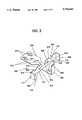
- FIG. 3 is an illustration of the insert of the rocker shown in FIG. 2.
- FIGS. 1, 2, and 3 correspond to FIGS. 1, 2, and 10, of the U.S. patent applications Ser. Nos. 08/489,462, 08/474,227, and 08/472,829 identified above and incorporated herein by reference.
- the reference numerals used in FIGS. 1, 2, and 3, having a reference numeral value of less than 300 correspond to the reference numerals in FIGS. 1, 2, and 10, of the above co-pending applications. All reference numerals of 300 or larger are not found in the above co-pending applications and are described herein relative to FIGS. 1, 2, 3, hereof.
- FIG. 1 there is illustrated a partial tape drive 10 of the type in which the invention may be used.
- FIG. 1 illustrates tape drive 10 with the cover removed for visibility and with bridge 12 exploded out of and removed from the tape drive chassis 1 I.
- the bridge 12 supports the magnetic read/write head positioning assembly 14.
- Read/write head positioning assembly 14 is illustrated in FIG. 2 in an exploded view and will be addressed in more detail with reference to that figure.
- Stepper motors 16 and 18 are supported by chassis 11 of the tape drive 10.
- Read/write head positioning stepper motor 16 through worm gear 20 provides the drive motion to move the read/write head positioning assembly 14 relative to bridge 12.
- Tape drive 10 is further provided with the capstan drive 22 necessary to feed the tape, not shown.
- Capstan drive 22 comprises a soft rubber wheel or roller to engage the tape of a cartridge, not shown, for feeding purposes and is driven by capstan drive motor 24.
- Voice Coil Motor (VCM) spring 88 is provided having a mounting pad or attachment pad 92 which permits the adhesive attachment of VCM spring 88 to the back surface 63 of vertical wall 64 with the voice coil 90 disposed within cavity 66.
- VCM spring 88 also has an oval span 98 intermediate the attachment pad 92 and the coil mount pad 94. The oval span 98 provides flexibility and the ability to move the coil mount pad 94 vertically within limits with the respect to attachment pad 92. While the stepper motor 16 drives the carriage 30 to provide coarse positioning, the movement of the voice coil 90 provides the fine positioning.
- connection tabs 96 which serve to accept a connecting material such as an epoxy to connect the coil mount pad 94 to the rocker 100 for bi-directional movement therewith.
- Rocker 100 is formed as a beam member 102 having a latch arm 104 extending from one side thereof. On the opposite end of beam member 102 from latch arm 104 is a push bar 106 attached by a web 108. Flexures or torsion spring arms 110 protrude from the sides of beam 102. Flexures or torsion spring arms 110 made of a thin leaf spring material have been formed with tabs 112 to assist in positioning flexures 110 within slots 114 of carriage 30. Resident within slots 114, flexures 110 provide adequate bending capability and capacity to permit the rocker 100 to oscillate over a limited oscillation range. Rocker 100 is further provided with recesses 116 into which connection tabs 96 are inserted and permanently attached by an epoxy or comparable adhesive material.
- the flexures or torsion spring arms 110 are very stiff in a vertical plane yet still have a relatively low torsional stiffness.
- the torsion spring arm 110 may be tailored further in its torsional spring resistance by the notching or scalloping 320 of the top and bottom edges 310, 312 to form a reduced cross section 314 in the arm 110.
- the extent of the notching or scalloping can be optimized to maximize vertical stiffness, minimize torsional stiffness and minimize flexural stress of the torsional spring arms 110.
- Recesses 116 form pockets which are chamfered on the sides to provide lead-in surfaces for the tabs 96 of the VCM mount pad 94. Also, the pockets or recesses 116 serve to contain and confine the bonding agent used to attach the tabs 96 to the insert 226 from which torsion arms 110 extend.
- Push bar 106 is engageable with and attached to beam spring end 74 of cantilever beam spring 72 which resides on the bottom of the spring 68.
- Push bar 106 is adhered with epoxy or comparable material to connect push bar 106 to the web 108 and magnetic head 82 assembly.
- Flexible web 108, an extension of insert 226 of FIG. 3, interconnects the end of beam 102 and push bar 106 and provides mobility to push bar 106 with respect to the end of beam 102, thereby accommodating any slight misalignment which might occur whenever rocker 100 pivots about flexure 110 and does not perfectly follow the translation of magnetic head 82.
- Web 108 further minimizes any forces caused by the rocker beam 102 which may tend to urge the magnetic head 82 away from the magnetic tape surface, thereby preventing degradation of the recording or reading of the data on the tape.
- Push bar 106 is preferably insert-molded around web 108.
- Pivot leaf spring 226 is comprised of a plurality of segments, particularly flexures 110 and flexure tabs 112. Extending from beam 228 interconnecting flexures 110 are beams 230 and 232. Beam 230 provides significant area in which the plastic of the rocker 100 as shown in FIG. 2 may be incorporated. This leaf spring 226 and particularly beams 230, 232 and the portion of beam 228 between flexures 110 may be insert-molded into the plastic. The push bar 106 of rocker 100 then may be insert-molded around the end of tab 234 with tab 234 providing the web 108 described earlier with respect to FIG. 2.
- flexure leaf spring 226 The formation of the flexure leaf spring 226 and its incorporation into rocker 100 by insert-molding enhances the precise control and the resilient return movement of rocker 100 and the movement of VCM coil 90 and magnetic head 82 in FIG. 2.
- Insert-molding leaf spring or insert 226 into stiff plastic securely fixes the plastic rocker body 100 of beam member 102 to the insert 226 with permanence and rigidity.
- Holes 316 serve to accept plastic to anchor the plastic body 100 to insert 226.
- Connecting holes 318 accept tabs 96 for attachment by bonding such as with epoxy.
Abstract
A pivot bearing structure formed of a leaf spring is incorporated into a rocker or force transmission member which whenever mounted to a carriage of a high density data tape drive system precisely defines the pivot axis of the rocker and provides a very high degree of stiffness in a vertical plane, that plane being parallel to the recording surface of the magnetic tape. The rocker derives motion from a voice coil motor (VCM) and transmits that controlled motion to a magnetic head which is suspended for movement in a vertical plane while in contact with a length of magnetic tape upon which data is recorded or from which data is read. The movement of the magnetic head may be very precisely controlled by energizing the VCM, because the pivot axis is extremely well defined due to the stiffness in the vertical plane of the pivot bearing. Movement of the VCM coil directly translates into movement of the magnetic head. The rocker is fabricated to form a cavity or pocket exposing a portion of the leaf spring to permit the bonding of another part to the leaf spring.
Description
This application is a continuation-in-part of: co-pending U.S. patent application Ser. No. 08/489,462 filed Jun. 7, 1995, by Eric A. Eckberg, Gerald D. Malagrino, Jr., and Brian L. Rappel; co-pending U.S. patent application Ser. No. 08/474,227 filed Jun. 7, 1995, by Eric A. Eckberg, Gerald D. Malagrino, Jr., and Brian L. Rappel; and U.S. patent application Ser. No. 08/472,819, now U.S. Pat. No. 5,677,806, filed Jun. 7, 1995, by Eric A. Eckberg, Gerald D. Malagrino, Jr., Brian L. Rappei, and Thomas D. Weller; all of which are incorporated hereinto by reference for purposes of disclosure.
This invention relates to precision force transmission members and more specifically to magnetic tape recorder head positioning drives having a force transmission member in order to position a magnetic head relative to a carriage of the tape recorder system.
In positioning the magnetic head relative to a carriage of a tape recorder for recording data on a magnetic tape, the need for precision is dictated to a very large extent by the track density of the recorded data. The data track recording density as well as the diminutive size of the tape, cartridge and recorder, all contribute to a requirement for a simple, reliable, low-inertia, inexpensive and highly precise apparatus for positioning the recording head of the magnetic tape read/write device.
The space available for a component and particularly for a force transmission member used to transmit drive forces from a voice coil motor to a suspended, movable magnetic head is highly restricted within the tape recorder and does not permit use of devices with conventional bearings.
Conventional bearings, such as roller bearings, not only are consumers of scarce space but also are expensive. The use of conventional bearings, even precision roller bearings, adversely affects the positioning of the magnetic head with respect to the magnetic tape.
Needing to simplify the structure of the device as well as to simplify the assembly thereof, the transmission member should be readily assembled along with the remainder of the carriage of the tape drive and then, preferably, not require any servicing or adjustments once assembled.
It is an object of the invention to provide a support having a high degree of stiffness in a vertical plane for a force transmission member within a tape drive mechanism.
It is another object of the invention to provide a force transmission member suspension which requires very little torque to pivotally displace the force transmission member through its range of motion.
It is still another object of the invention to provide a suspension for the force transmission member which will not require servicing or adjustment.
It is a further object of the invention to provide a support for the force transmission member with a well defined pivot axis location with very low-level controlled torque forces for displacement and restoration.
It is still a further object of the invention to provide access to the insert molded metal member to permit attachment of another metal part to the insert molded member in a region otherwise surrounded by the plastic of the rocker body.
The shortcomings of the prior art are overcome and the objects of the invention accomplished by supporting a rocker member on a leaf spring torsion bearing having a high degree of stiffness in a vertical plane.
The location of the pivot axis for a force transmission member within the carriage of a tape drive is defined by the use of a leaf spring extending from the body of the force transmission member or rocker and supported by the carriage of the tape drive. The carriage is provided with mounting slots formed into its structural members to accommodate the leaf springs, thereby forming the pivot, and at the same time serving as a mounting datum having consistency relative to the carriage structure.
The leaf spring is formed as a portion of a sheet metal insert. The insert is thereafter insert-molded into a stiff plastic part which forms a body of the force transmission member or rocker. In addition to the torsion spring arms of the leaf spring, the insert also has beams that are substantially enclosed within the stiff plastic body of the force transmission member. The body of the force transmission member or rocker is formed so as to provide recesses disposed and formed to expose attachment slots in one beam of the insert, thereby permitting the bonding of connection tabs of a voice coil motor (VCM) support spring to the rocker at controlled locations. The recesses not only provide access to the beam within the body of the rocker but also act to hold and control the flow of bonding agents used to attach the connection tabs of the voice coil motor support spring to the beam of the insert within the force transmission member after molding and during assembly. The arms forming the torsion spring extend from the body of the rocker and may be formed to provide tabs bent substantially perpendicular to the arms. The tabs restrain movement of the rocker and the spring arms in the direction substantially co-axial to the axis of the arms.
Further, the torsion spring arms are narrowed at selected locations to reduce the width of the arms, thereby reducing the force per degree of rotation necessary to move the rocker. The notching or reduction of the width of the arms is accomplished while maintaining the stiffness in a vertical direction. The axis of rotation is well defined by the torsion axis of the spring arms; and due to the nature of the torsion arms, the axis of rotation remains fixed and consistent relative to the carriage of the tape drive actuator.
The insert, being insert-molded into the stiff plastic rocker, results in a composite having a very defined pivot axis with respect to the axis of the pivot arms. The insert-molding provides a consistent and reliable part without any need to attach the insert to the plastic body, a post-molding attachment operation. A more complete understanding of the invention and its advantage and operation may be had from the attached drawing and detailed description of the invention to follow.
FIG. 1 illustrates a partially exploded view of a high density data storage tape drive system.
FIG. 2 is an exploded view of the actuator of the tape drive illustrated in FIG. 1.
FIG. 3 is an illustration of the insert of the rocker shown in FIG. 2.
FIGS. 1, 2, and 3, correspond to FIGS. 1, 2, and 10, of the U.S. patent applications Ser. Nos. 08/489,462, 08/474,227, and 08/472,829 identified above and incorporated herein by reference. The reference numerals used in FIGS. 1, 2, and 3, having a reference numeral value of less than 300 correspond to the reference numerals in FIGS. 1, 2, and 10, of the above co-pending applications. All reference numerals of 300 or larger are not found in the above co-pending applications and are described herein relative to FIGS. 1, 2, 3, hereof.
Referring initially to FIG. 1, there is illustrated a partial tape drive 10 of the type in which the invention may be used.
FIG. 1 illustrates tape drive 10 with the cover removed for visibility and with bridge 12 exploded out of and removed from the tape drive chassis 1 I. The bridge 12 supports the magnetic read/write head positioning assembly 14. Read/write head positioning assembly 14 is illustrated in FIG. 2 in an exploded view and will be addressed in more detail with reference to that figure.
Voice Coil Motor (VCM) spring 88 is provided having a mounting pad or attachment pad 92 which permits the adhesive attachment of VCM spring 88 to the back surface 63 of vertical wall 64 with the voice coil 90 disposed within cavity 66. VCM spring 88 also has an oval span 98 intermediate the attachment pad 92 and the coil mount pad 94. The oval span 98 provides flexibility and the ability to move the coil mount pad 94 vertically within limits with the respect to attachment pad 92. While the stepper motor 16 drives the carriage 30 to provide coarse positioning, the movement of the voice coil 90 provides the fine positioning.
Extending from the bottom portion of coil mount pad 94 are connection tabs 96 which serve to accept a connecting material such as an epoxy to connect the coil mount pad 94 to the rocker 100 for bi-directional movement therewith.
Rocker 100 is formed as a beam member 102 having a latch arm 104 extending from one side thereof. On the opposite end of beam member 102 from latch arm 104 is a push bar 106 attached by a web 108. Flexures or torsion spring arms 110 protrude from the sides of beam 102. Flexures or torsion spring arms 110 made of a thin leaf spring material have been formed with tabs 112 to assist in positioning flexures 110 within slots 114 of carriage 30. Resident within slots 114, flexures 110 provide adequate bending capability and capacity to permit the rocker 100 to oscillate over a limited oscillation range. Rocker 100 is further provided with recesses 116 into which connection tabs 96 are inserted and permanently attached by an epoxy or comparable adhesive material. The flexures or torsion spring arms 110 are very stiff in a vertical plane yet still have a relatively low torsional stiffness. The torsion spring arm 110 may be tailored further in its torsional spring resistance by the notching or scalloping 320 of the top and bottom edges 310, 312 to form a reduced cross section 314 in the arm 110. The extent of the notching or scalloping can be optimized to maximize vertical stiffness, minimize torsional stiffness and minimize flexural stress of the torsional spring arms 110.
Referring now to FIG. 3, an insert or pivot leaf spring 226 is illustrated. Pivot leaf spring 226 is comprised of a plurality of segments, particularly flexures 110 and flexure tabs 112. Extending from beam 228 interconnecting flexures 110 are beams 230 and 232. Beam 230 provides significant area in which the plastic of the rocker 100 as shown in FIG. 2 may be incorporated. This leaf spring 226 and particularly beams 230, 232 and the portion of beam 228 between flexures 110 may be insert-molded into the plastic. The push bar 106 of rocker 100 then may be insert-molded around the end of tab 234 with tab 234 providing the web 108 described earlier with respect to FIG. 2.
The formation of the flexure leaf spring 226 and its incorporation into rocker 100 by insert-molding enhances the precise control and the resilient return movement of rocker 100 and the movement of VCM coil 90 and magnetic head 82 in FIG. 2. Insert-molding leaf spring or insert 226 into stiff plastic securely fixes the plastic rocker body 100 of beam member 102 to the insert 226 with permanence and rigidity. Holes 316 serve to accept plastic to anchor the plastic body 100 to insert 226. Connecting holes 318 accept tabs 96 for attachment by bonding such as with epoxy.
It will be recognized by one skilled in the art that minor variations and modifications to the invention may be made without removing the apparatus from the scope of the appended claims which define the application.
Claims (9)
1. A high density data storage tape drive for use with a cartridge containing a length of storage tape, comprising:
a frame;
a drive mechanism supported on said time to spool said tape;
a read/write head disposed adjacent said tape;
an electrical drive having a fixed portion and a movable portion;
said head supported on And movable with respect to a carriage, said carriage displaceable relative to said tape in coarse increments;
a pivotable force transmission member engaged with said head and said movable portion of said electrical drive for transmitting movement of said movable portion of said electrical drive to said head, thereby displacing said head relative to said carriage and the tape in fine increments;
said force transmission member including a leaf spring secured to said carriage and having a scalloped edge defining a pivot bearing said scalloped edge provided in a plane parallel to a plane of a recording surface of the storage tape, said scalloped edge of said leaf spring providing reduced stress per degree of rotation at said pivot bearing with an axis parallel to said plane of the storage tape.
2. The high density data storage tape drive of claim 1 wherein said leaf spring is connected to said head for controlling movement thereof responsive to movement of said movable portion of said electrical drive.
3. The high density data storage tape drive of claim 2 wherein said electrical drive comprises a voice coil motor.
4. The high density data storage tape drive of claim 3 wherein said force transmission member further comprises a projecting portion spanning between one end of said force transmission member and said head and disposed in the direction of movement of said head, said projecting portion deflectable to accommodate misalignment of said head and said force transmission member during various phases of movement of said leaf spring and said head.
5. A high density data storage tape drive for use with a cartridge containing a length of storage tape, comprising:
a frame;
a drive mechanism supported on said flame to spool said tape;
a read/write head disposed adjacent said tape;
said head supported on and moveable with respect to a carriage, said carriage displaceable relative to the tape in coarse increments;
a pivotable force transmission member engaged with said head and a movable portion of a voice coil motor for transmitting movement of said movable portion of said voice coil motor to said head, thereby displacing said head relative to said carriage and the tape in fine increments;
said force transmission member including a metal leaf spring secured to said carriage and insert-molded into a rocker engaged with said head and said movable portion of said voice coil motor, wherein said metal leaf spring allows pivotable movement of said head relative to said rocker about an axis substantially parallel to a plane of a recording surface of the storage tape while providing a high degree of stiffness in the plane substantially parallel to the recording surface of the storage tape.
6. A high density data storage tape drive of claim 5 wherein said metal leaf spring in its engagement with said carriage is disposed to provide a high degree of stiffness in a plane substantially parallel to a plane of movement of said movable portion of said voice coil motor and a low resistance to torsion within said leaf spring.
7. The high density data storage tape drive of claim 5 wherein said metal leaf spring in its engagement with said carriage is disposed with ends of said leaf spring confined in slots formed into said carriage.
8. The high density data storage tape drive of claim 6 wherein said force transmission member further comprises a projecting portion spanning between one end of said force transmission member and said head and disposed in the direction of movement of said head, said projecting portion deflectable to accommodate misalignment of said head and said force transmission member during various phases of movement of said leaf spring and said head.
9. A high density data storage tape drive for use with a cartridge containing a length of storage tape, comprising:
a frame;
a drive mechanism supported on said frame to spool said tape;
a read/write head disposed adjacent said tape;
said head supported on and movable with respect to a carriage, said carriage displaceable relative to the tape in coarse increments;
a pivotable force transmission member engaged with said head and a movable portion of a voice coil motor for transmitting movement of said movable portion of said voice coil motor to said head, thereby displacing said head relative to said carriage and the tape in fine increments;
said force transmission member including a metal leaf spring secured to said carriage and insert-molded into a rocker engaged with said head and said movable portion of said voice coil motor, said rocker including a pocket exposing a portion of said metal leaf spring, said movable portion of said voice coil motor including a metal mating member bonded to exposed portions of said metal leaf spring wherein said metal leaf spring allows pivotable movement of said head relative to said rocker about an axis substantially parallel to a plane of a recording surface of the storage tape while providing a high degree of stiffness in the plane substantially parallel to the recording surface of the storage tape.
Priority Applications (1)
| Application Number | Priority Date | Filing Date | Title |
|---|---|---|---|
| US08/586,505 US5710681A (en) | 1995-06-07 | 1996-01-16 | Pivot bearing having no moving parts for use in a high density data tape drive |
Applications Claiming Priority (4)
| Application Number | Priority Date | Filing Date | Title |
|---|---|---|---|
| US08/489,462 US5726834A (en) | 1995-06-07 | 1995-06-07 | Actuator for servo actuated tape drive |
| US08/474,227 US5793573A (en) | 1995-06-07 | 1995-06-07 | Hybrid actuator servo actuated tape drive having a pivotally mounted motion transmission member |
| US08/472,829 US5677806A (en) | 1995-06-07 | 1995-06-07 | Head locking apparatus in a servo system so that the head can read and write data on a tape without servo trucks |
| US08/586,505 US5710681A (en) | 1995-06-07 | 1996-01-16 | Pivot bearing having no moving parts for use in a high density data tape drive |
Related Parent Applications (3)
| Application Number | Title | Priority Date | Filing Date |
|---|---|---|---|
| US08/489,462 Continuation-In-Part US5726834A (en) | 1995-06-07 | 1995-06-07 | Actuator for servo actuated tape drive |
| US08/474,227 Continuation-In-Part US5793573A (en) | 1995-06-07 | 1995-06-07 | Hybrid actuator servo actuated tape drive having a pivotally mounted motion transmission member |
| US08/472,829 Continuation-In-Part US5677806A (en) | 1995-06-07 | 1995-06-07 | Head locking apparatus in a servo system so that the head can read and write data on a tape without servo trucks |
Publications (1)
| Publication Number | Publication Date |
|---|---|
| US5710681A true US5710681A (en) | 1998-01-20 |
Family
ID=27413220
Family Applications (1)
| Application Number | Title | Priority Date | Filing Date |
|---|---|---|---|
| US08/586,505 Expired - Fee Related US5710681A (en) | 1995-06-07 | 1996-01-16 | Pivot bearing having no moving parts for use in a high density data tape drive |
Country Status (1)
| Country | Link |
|---|---|
| US (1) | US5710681A (en) |
Cited By (7)
| Publication number | Priority date | Publication date | Assignee | Title |
|---|---|---|---|---|
| US5949619A (en) * | 1995-06-07 | 1999-09-07 | International Business Machines Corporation | Servo actuated read/write head actuator assembly for a tape drive |
| US6721126B1 (en) | 2000-08-16 | 2004-04-13 | International Business Machines Corporation | Position identification for a coarse actuator portion of a compound actuator |
| US20090201604A1 (en) * | 2008-02-08 | 2009-08-13 | International Business Machines Corporation | Balanced linkage actuation of tape head |
| US9805751B1 (en) * | 2017-01-20 | 2017-10-31 | Oracle International Corporation | Record head actuator sandwiched damper plus travel limiter |
| US10854236B1 (en) | 2019-09-11 | 2020-12-01 | International Business Machines Corporation | Dynamic tape guide bearing tilt mechanism |
| US10957362B1 (en) | 2019-09-11 | 2021-03-23 | International Business Machines Corporation | Non-interfering micro-positioning system utilizing piezoelectric elements |
| US11056139B2 (en) * | 2019-09-11 | 2021-07-06 | International Business Machines Corporation | Semi-flexible structure for micro-positioning a write/read head |
Citations (23)
| Publication number | Priority date | Publication date | Assignee | Title |
|---|---|---|---|---|
| US4215377A (en) * | 1978-10-10 | 1980-07-29 | Norris Elwood G | Multi-speed tape cassette system |
| US4363046A (en) * | 1980-05-24 | 1982-12-07 | Sony Corporation | Deflectable transducer head assembly |
| US4627039A (en) * | 1983-12-23 | 1986-12-02 | Magnetic Peripherals Inc. | Head positioning servo system for optical recording with coarse and fine control |
| US4646183A (en) * | 1984-05-11 | 1987-02-24 | North Atlantic Industries, Inc. | Tracking head suspension for tape deck |
| US4769732A (en) * | 1984-07-28 | 1988-09-06 | Masato Tanaka | Magnetic tape cassette |
| US4858047A (en) * | 1988-12-06 | 1989-08-15 | Colorado Memory Systems, Inc. | Fine head positioning system for a tape backup drive |
| US4864448A (en) * | 1986-12-04 | 1989-09-05 | Sony Corporation | Tape cassette |
| US4943877A (en) * | 1988-12-06 | 1990-07-24 | Colorado Memory Systems, Inc. | Fine head positioning system for a tape backup device |
| US5016123A (en) * | 1989-10-05 | 1991-05-14 | Eastman Kodak Company | Apparatus for magnetically determining the status of a cartridge in a magnetic recorder |
| US5040082A (en) * | 1989-02-07 | 1991-08-13 | Sony Corporation | Recording apparatus |
| US5047883A (en) * | 1990-02-07 | 1991-09-10 | Ampex Corporation | Pantograph head mount having double leaves integral with a rigid tip structure |
| US5091808A (en) * | 1989-08-07 | 1992-02-25 | Nigam Anil K | Two-motor servo mechanism system for a magnetic disk drive |
| US5191492A (en) * | 1990-03-30 | 1993-03-02 | Archive Corporation | Mechanisms for a closed loop head positioner for streaming tape drives |
| US5239437A (en) * | 1991-08-12 | 1993-08-24 | Minnesota Mining And Manufacturing Company | Self identifying universal data storage element |
| US5253136A (en) * | 1990-08-30 | 1993-10-12 | Sony Corporation | Tape cassette having an information indicating portion for indicating information relating to predetermined characteristics of the tape cassette |
| US5268802A (en) * | 1991-05-28 | 1993-12-07 | Iomega Corporation | Reading non-standard tapes on tape drives |
| US5270886A (en) * | 1989-08-07 | 1993-12-14 | Antek Peripherals, Inc. | Two motor servo system for a removable disk drive |
| US5277503A (en) * | 1991-07-22 | 1994-01-11 | Brother Kogyo Kabushiki Kaisha | Tape cassette built into a tape writer |
| US5280402A (en) * | 1991-08-30 | 1994-01-18 | Minnesota Mining And Manufacturing Company | Combined stepper motor and voice coil head positioning apparatus |
| US5325243A (en) * | 1988-11-10 | 1994-06-28 | U.S. Philips Corporation | System for selectively interfacing information carriers by physically accepting cassettes |
| US5327305A (en) * | 1992-08-14 | 1994-07-05 | Conner Peripherals, Inc. | Tape format detection system |
| US5331490A (en) * | 1990-10-31 | 1994-07-19 | Hewlett-Packard Company | Tape head fine positioning system for a tape backup drive |
| US5379170A (en) * | 1992-04-13 | 1995-01-03 | Minnesota Mining And Manufacturing Company | Dynamically adjustable head positioning mechanism for tape drives |
-
1996
- 1996-01-16 US US08/586,505 patent/US5710681A/en not_active Expired - Fee Related
Patent Citations (23)
| Publication number | Priority date | Publication date | Assignee | Title |
|---|---|---|---|---|
| US4215377A (en) * | 1978-10-10 | 1980-07-29 | Norris Elwood G | Multi-speed tape cassette system |
| US4363046A (en) * | 1980-05-24 | 1982-12-07 | Sony Corporation | Deflectable transducer head assembly |
| US4627039A (en) * | 1983-12-23 | 1986-12-02 | Magnetic Peripherals Inc. | Head positioning servo system for optical recording with coarse and fine control |
| US4646183A (en) * | 1984-05-11 | 1987-02-24 | North Atlantic Industries, Inc. | Tracking head suspension for tape deck |
| US4769732A (en) * | 1984-07-28 | 1988-09-06 | Masato Tanaka | Magnetic tape cassette |
| US4864448A (en) * | 1986-12-04 | 1989-09-05 | Sony Corporation | Tape cassette |
| US5325243A (en) * | 1988-11-10 | 1994-06-28 | U.S. Philips Corporation | System for selectively interfacing information carriers by physically accepting cassettes |
| US4943877A (en) * | 1988-12-06 | 1990-07-24 | Colorado Memory Systems, Inc. | Fine head positioning system for a tape backup device |
| US4858047A (en) * | 1988-12-06 | 1989-08-15 | Colorado Memory Systems, Inc. | Fine head positioning system for a tape backup drive |
| US5040082A (en) * | 1989-02-07 | 1991-08-13 | Sony Corporation | Recording apparatus |
| US5270886A (en) * | 1989-08-07 | 1993-12-14 | Antek Peripherals, Inc. | Two motor servo system for a removable disk drive |
| US5091808A (en) * | 1989-08-07 | 1992-02-25 | Nigam Anil K | Two-motor servo mechanism system for a magnetic disk drive |
| US5016123A (en) * | 1989-10-05 | 1991-05-14 | Eastman Kodak Company | Apparatus for magnetically determining the status of a cartridge in a magnetic recorder |
| US5047883A (en) * | 1990-02-07 | 1991-09-10 | Ampex Corporation | Pantograph head mount having double leaves integral with a rigid tip structure |
| US5191492A (en) * | 1990-03-30 | 1993-03-02 | Archive Corporation | Mechanisms for a closed loop head positioner for streaming tape drives |
| US5253136A (en) * | 1990-08-30 | 1993-10-12 | Sony Corporation | Tape cassette having an information indicating portion for indicating information relating to predetermined characteristics of the tape cassette |
| US5331490A (en) * | 1990-10-31 | 1994-07-19 | Hewlett-Packard Company | Tape head fine positioning system for a tape backup drive |
| US5268802A (en) * | 1991-05-28 | 1993-12-07 | Iomega Corporation | Reading non-standard tapes on tape drives |
| US5277503A (en) * | 1991-07-22 | 1994-01-11 | Brother Kogyo Kabushiki Kaisha | Tape cassette built into a tape writer |
| US5239437A (en) * | 1991-08-12 | 1993-08-24 | Minnesota Mining And Manufacturing Company | Self identifying universal data storage element |
| US5280402A (en) * | 1991-08-30 | 1994-01-18 | Minnesota Mining And Manufacturing Company | Combined stepper motor and voice coil head positioning apparatus |
| US5379170A (en) * | 1992-04-13 | 1995-01-03 | Minnesota Mining And Manufacturing Company | Dynamically adjustable head positioning mechanism for tape drives |
| US5327305A (en) * | 1992-08-14 | 1994-07-05 | Conner Peripherals, Inc. | Tape format detection system |
Cited By (9)
| Publication number | Priority date | Publication date | Assignee | Title |
|---|---|---|---|---|
| US5949619A (en) * | 1995-06-07 | 1999-09-07 | International Business Machines Corporation | Servo actuated read/write head actuator assembly for a tape drive |
| US6721126B1 (en) | 2000-08-16 | 2004-04-13 | International Business Machines Corporation | Position identification for a coarse actuator portion of a compound actuator |
| US20090201604A1 (en) * | 2008-02-08 | 2009-08-13 | International Business Machines Corporation | Balanced linkage actuation of tape head |
| US7839598B2 (en) * | 2008-02-08 | 2010-11-23 | International Business Machines Corporation | Balanced linkage actuation of tape head |
| US9805751B1 (en) * | 2017-01-20 | 2017-10-31 | Oracle International Corporation | Record head actuator sandwiched damper plus travel limiter |
| US10217479B2 (en) | 2017-01-20 | 2019-02-26 | Oracle International Corporation | Record head actuator sandwiched damper plus travel limiter |
| US10854236B1 (en) | 2019-09-11 | 2020-12-01 | International Business Machines Corporation | Dynamic tape guide bearing tilt mechanism |
| US10957362B1 (en) | 2019-09-11 | 2021-03-23 | International Business Machines Corporation | Non-interfering micro-positioning system utilizing piezoelectric elements |
| US11056139B2 (en) * | 2019-09-11 | 2021-07-06 | International Business Machines Corporation | Semi-flexible structure for micro-positioning a write/read head |
Similar Documents
| Publication | Publication Date | Title |
|---|---|---|
| US5379170A (en) | Dynamically adjustable head positioning mechanism for tape drives | |
| US5949619A (en) | Servo actuated read/write head actuator assembly for a tape drive | |
| US5726834A (en) | Actuator for servo actuated tape drive | |
| US4616355A (en) | Optical head device | |
| US4630158A (en) | Vertically loading head module for magnetic disk drive | |
| KR20000004950A (en) | Multipiece intergrated suspension assembly for a magnetic storage system | |
| WO1995026026A1 (en) | Reading/writing information on a storage medium | |
| EP1058238B1 (en) | Head suspension assembly of disk drive | |
| US5710681A (en) | Pivot bearing having no moving parts for use in a high density data tape drive | |
| US6404598B1 (en) | Flexible circuit routing configuration for a fine/coarse positioner for a tape drive | |
| CA1263182A (en) | Magnetic head supporting device | |
| US4849840A (en) | Carriage device for floppy disk apparatus having head arm with regulating material | |
| EP0314515B1 (en) | Disc drive incorporating automatic wear compensation for a pivoted arm | |
| US5739984A (en) | damping loop for a tape drive actuator with a servo control system | |
| EP0396393B1 (en) | An actuator arm for a disc drive | |
| US4456936A (en) | Cantilevered transducer carriage | |
| US4745504A (en) | Disc memory head positioner | |
| US20030007294A1 (en) | Actuator arm for data storage disc drives | |
| US6137651A (en) | Flexured mounting system for friction reduction and friction linearization in linear actuator for disk drive | |
| US5504636A (en) | Magnetic disk apparatus having improved support for head assembly | |
| JPH0786980B2 (en) | Objective lens drive | |
| US5648883A (en) | Disc drive having positional shift adjustment | |
| EP0448338B1 (en) | A rotary actuator head positioning apparatus and dual pivot apparatus for a disk drive | |
| US5943192A (en) | Magnetic head supporting mechanism for a slider bearing member and method for assembling magnetic disk storage comprising the same | |
| US5621576A (en) | Optical head for optical memory disk recording device with elastic support in a direction parallel to a recording surface |
Legal Events
| Date | Code | Title | Description |
|---|---|---|---|
| AS | Assignment |
Owner name: INTERNATIONAL BUSINESS MACHINES CORPORATION, NEW Y Free format text: ASSIGNMENT OF ASSIGNORS INTEREST;ASSIGNORS:ECKBERG, ERIC A.;MALAGRINO, GERALD D. JR.;RAPPEL, BRIAN L.;REEL/FRAME:007926/0706;SIGNING DATES FROM 19960111 TO 19960415 |
|
| REMI | Maintenance fee reminder mailed | ||
| LAPS | Lapse for failure to pay maintenance fees | ||
| LAPS | Lapse for failure to pay maintenance fees |
Free format text: PATENT EXPIRED FOR FAILURE TO PAY MAINTENANCE FEES (ORIGINAL EVENT CODE: EXP.); ENTITY STATUS OF PATENT OWNER: LARGE ENTITY |
|
| STCH | Information on status: patent discontinuation |
Free format text: PATENT EXPIRED DUE TO NONPAYMENT OF MAINTENANCE FEES UNDER 37 CFR 1.362 |
|
| FP | Lapsed due to failure to pay maintenance fee |
Effective date: 20020120 |