US5898399A - Subchirp processing method - Google Patents
Subchirp processing method Download PDFInfo
- Publication number
- US5898399A US5898399A US08/644,329 US64432996A US5898399A US 5898399 A US5898399 A US 5898399A US 64432996 A US64432996 A US 64432996A US 5898399 A US5898399 A US 5898399A
- Authority
- US
- United States
- Prior art keywords
- subaperture
- rma
- azimuth
- steps
- generate
- Prior art date
- Legal status (The legal status is an assumption and is not a legal conclusion. Google has not performed a legal analysis and makes no representation as to the accuracy of the status listed.)
- Expired - Lifetime
Links
Images


Classifications
-
- G—PHYSICS
- G01—MEASURING; TESTING
- G01S—RADIO DIRECTION-FINDING; RADIO NAVIGATION; DETERMINING DISTANCE OR VELOCITY BY USE OF RADIO WAVES; LOCATING OR PRESENCE-DETECTING BY USE OF THE REFLECTION OR RERADIATION OF RADIO WAVES; ANALOGOUS ARRANGEMENTS USING OTHER WAVES
- G01S13/00—Systems using the reflection or reradiation of radio waves, e.g. radar systems; Analogous systems using reflection or reradiation of waves whose nature or wavelength is irrelevant or unspecified
- G01S13/88—Radar or analogous systems specially adapted for specific applications
- G01S13/89—Radar or analogous systems specially adapted for specific applications for mapping or imaging
- G01S13/90—Radar or analogous systems specially adapted for specific applications for mapping or imaging using synthetic aperture techniques, e.g. synthetic aperture radar [SAR] techniques
- G01S13/904—SAR modes
- G01S13/9054—Stripmap mode
-
- G—PHYSICS
- G01—MEASURING; TESTING
- G01S—RADIO DIRECTION-FINDING; RADIO NAVIGATION; DETERMINING DISTANCE OR VELOCITY BY USE OF RADIO WAVES; LOCATING OR PRESENCE-DETECTING BY USE OF THE REFLECTION OR RERADIATION OF RADIO WAVES; ANALOGOUS ARRANGEMENTS USING OTHER WAVES
- G01S13/00—Systems using the reflection or reradiation of radio waves, e.g. radar systems; Analogous systems using reflection or reradiation of waves whose nature or wavelength is irrelevant or unspecified
- G01S13/88—Radar or analogous systems specially adapted for specific applications
- G01S13/89—Radar or analogous systems specially adapted for specific applications for mapping or imaging
- G01S13/90—Radar or analogous systems specially adapted for specific applications for mapping or imaging using synthetic aperture techniques, e.g. synthetic aperture radar [SAR] techniques
- G01S13/904—SAR modes
- G01S13/9056—Scan SAR mode
-
- G—PHYSICS
- G01—MEASURING; TESTING
- G01S—RADIO DIRECTION-FINDING; RADIO NAVIGATION; DETERMINING DISTANCE OR VELOCITY BY USE OF RADIO WAVES; LOCATING OR PRESENCE-DETECTING BY USE OF THE REFLECTION OR RERADIATION OF RADIO WAVES; ANALOGOUS ARRANGEMENTS USING OTHER WAVES
- G01S13/00—Systems using the reflection or reradiation of radio waves, e.g. radar systems; Analogous systems using reflection or reradiation of waves whose nature or wavelength is irrelevant or unspecified
- G01S13/88—Radar or analogous systems specially adapted for specific applications
- G01S13/89—Radar or analogous systems specially adapted for specific applications for mapping or imaging
- G01S13/90—Radar or analogous systems specially adapted for specific applications for mapping or imaging using synthetic aperture techniques, e.g. synthetic aperture radar [SAR] techniques
- G01S13/904—SAR modes
Definitions
- the present invention relates generally to radar imaging and, more particularly, to a method of performing the initial azimuth FFT in a synthetic aperture radar system utilizing the range migration technique for image formation.
- Synthetic aperture radar has become an invaluable remote-sensing tool. To achieve the finest resolution, focused SAR is used, wherein some process is used to modify received signal histories to mitigate the detrimental effects of scatterer motion through range and doppler resolution cells.
- One approach to focussed SAR involves the use of polar format (PF) processing 1 .
- PF polar format
- RMA range migration algorithm
- Both the PF and RMA techniques have their advantages and disadvantages 2 .
- PF is typically less computationally intensive and more memory efficient, but systems based on the RMA are capable of producing well-focused, fine-resolution images over a wider area scene.
- the RMA provides an exact solution to the problem of range curvature. Fine-resolution, large scene images produced using the RMA do not suffer the geometric (keystone) distortion or residual quadratic phase errors inherent in conventional PF processing;
- the RMA can produce large scene size images free of subpatch and subswath boundaries. Such images are better suited for coherent-based image enhancement and exploitation techniques;
- the RMA is directly capable of processing spotlight, stripmap, and scan-mode SAR images. These advantages become increasingly significant with improvements in SAR system resolution and area coverage.
- the RMA is particularly useful in fine-resolution SAR systems operating at low frequencies, typically in systems designed for foliage penetration (FOPEN) and ground penetration (GPEN) applications.
- the present invention resides in a fast computational method of performing the computer-intensive initial steps of the range migration algorithm, or RMA.
- This subchirp processing method thus provides a computationally and memory efficient digital processing technique capable of producing SAR imagery of higher quality than the current polar format (PF) processing approach, while operating faster and more efficiently than the standard RMA.
- the invention provides a method of performing the initial azimuth FFT portion of the RMA by subdividing the azimuth-chirped signal history into a plurality of non-overlapping subapertures. An FFT is then separately applied to each subaperture and the results are coherently combined, after which the remaining steps of the conventional RMA may be completed.
- the invention is applicable to spotlight, stripmap and scan-mode SAR image formation, and the separate, subaperture Fourier transformations may be performed simultaneously in a parallel or distributed processing architecture.
- a more comprehensive summary of the method, including steps otherwise performed as part of the RMA, includes receiving signal history data and motion compensating the signal history data to a fixed scene point.
- the signal history is then subdivided into a plurality of non-overlapping subapertures, and a Fourier transformation is carried out on each subaperture separately.
- the results of the separate Fourier transformations are shifted and coherently summed to produce full-bandwidth transform data, which is then range-dimension resampled and inverse Fourier transformed in two dimensions to yield an output image.
- a key advantage of the invention is that the full-bandwidth transform data contains fewer azimuthal samples then conventional RMA procedures, thereby realizing a significant savings in computational and memory requirements.
- FIG. 1 is a block diagram used to illustrate procedural steps associated with the range migration algorithm
- FIG. 2 is a diagram relating to strip map motion compensation
- FIG. 3 is a diagram relating to spotlight motion compensation
- FIG. 4 is a block diagram providing a comparison between a conventional range migration algorithm (RMA), and the RMA incorporating subchirp processing according to this invention
- FIG. 5 presents a procedural block diagram and associated drawings which illustrate the subchirp processing method
- FIG. 6 is a diagram used to illustrate motion compensation requirements for the subchirp processing method
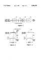
- FIG. 7(a) is a simulated point target image formed via conventional range migration processing
- FIG. 7(b) shows the simulated point target image of FIG. 7(a) formed through subchirp processing
- FIG. 8 depicts the basic components in a synthetic aperture radar (SAR) sensor of the type used to provide data as input to the method of the present invention.
- SAR synthetic aperture radar
- FIG. 1 A simplified model of the RMA is provided in FIG. 1.
- an azimuth fast Fourier transform FFT
- Two-dimensional phase compensation is then carried out at step 104.
- a one-dimensional range-dimension resampling known as Stolt interpolation, is performed at block 106, followed by a two-dimensional inverse FFT at 108 to output a complex image.
- a significant disadvantage of the RMA is that it must operate on the azimuth-chirped signal data directly, necessitating high along-track sampling rates at the front-end of the RMA processor. That is, the RMA operates on signal history data which has been motion compensated to a sliding point, (i.e., compensated to a line as in strip map mode as shown in FIG. 2) rather than to a fixed scene point (as in FIG. 3), which is generally performed in conjunction with spotlight processing algorithms. SAR signal data compensated in this manner has much higher total Doppler bandwidth due to the presence of a large instantaneous Doppler offset (carrier) frequency.
- the standard spotlight PF procedure partially removes this azimuth offset frequency through adjustment of receiver range gates and starting phase from pulse-to-pulse (motion compensation) during data collection, permitting lower pulse repetition frequency (PRF) operation than would otherwise be required.
- PRF pulse repetition frequency
- the RMA procedure dictates a reinstatement of the full Doppler carrier (azimuth chirp) after data collection and transmission but prior to the azimuth FFT step of the algorithm which, in turn, requires that the signal history first be upsampled in azimuth relative to the collection PRF.
- the required unsampling may be 10:1 or higher. This large unsampling of recorded signal history data often represents an unacceptable computational burden and memory inefficiency.
- This invention replaces the first along-track FFT of the RMA with other operations which facilitate effective computation of the transform at a much lower sampling rate.
- the method may be viewed as a substitute for the first azimuth FFT of the RMA with minor adjustments to the succeeding RMA steps.
- FIG. 4 illustrates this substitution.
- processing begins with the collected complex phase history data with motion compensation to scene center.
- the usual RMA process (on the left) must immediately upsample the data by a large factor, add the full bandwidth azimuth chirp modulation associated with the data collection geometry, and calculate an azimuth FFT over the upsampled data.
- the subchirp process (on the right) breaks the azimuth aperture into a number of shorter subapertures and adds a low bandwidth chirp across each subaperture. While the subchirp process must upsample an optimally-sampled signal history by a small factor, the resulting sample rate is often below the data collection PRF (pulse repetition frequency). Subchirp processing does not reduce or affect the required transmit PRF.
- the invention exploits the fact that the instantaneous bandwidth of an azimuth scene is much lower than total Doppler bandwidth required to achieve desired azimuth resolution.
- This principle is analogous to the SAR range dimension in systems using dechirp-on-receive, where the intermediate frequency (IF) bandwidth due to the range swath is much lower than transmitted RF bandwidth, permitting reduced analog-to-digital sampling rates.
- the method is applicable to all existing SAR imaging modes.
- the subchirp processing procedure is depicted in FIG. 5.
- the complex SAR signal history data 502 are first motion compensated at block 504 with respect to a fixed scene point (the standard spotlight-mode procedure), allowing a presum at 506 to a reduced sampling rate commensurate with the azimuth scene size of a processed image.
- the method then breaks the signal history aperture into a number of non-overlapping subapertures at step 508, depending on system parameters and collection geometry.
- the azimuth chirp (which was removed by motion compensation to a fixed point) is then reapplied at 510 in a modified form.
- the linear phase component of the chirp over each subaperture is not applied, as it is this large linear phase which creates the need for increased sampling rates.
- the effective motion compensation line is thus a linear segment approximation to a quadratic, as seen in FIG. 6.
- each subaperture is Fourier transformed separately at block 512, then the results are shifted and coherently summed at 514 with appropriate phase adjustments to obtain the desired, full bandwidth transform 516.
- RMA processing can proceed as depicted in FIG. 1, typically with some minor adjustments to the two-dimensional matched filter as applied.
- the final image is then formed via a two-dimensional inverse FFT.
- FIG. 7(a) shows the simulated point target array after standard RMA processing. A 2048-point FFT was required to produce the image.
- FIG. 7(b) shows the same image processed using subchirp processing. The invention yields the same image, but with only four 256-point FFT's, which represents a substantial computational savings over standard RMA processing. Additionally, the final azimuth inverse FFT was reduced to only 1280 samples by use of the procedure.
- FIG. 8 depicts basic components in a SAR system responsible for the generation, collection and initial processing of received signals for archiving, display, or other purposes. This figure is taken from “Spotlight Synthetic Aperture Radar: Signal Processing Algorithms," W. Carrara, R. Goodman, R. Majowski, Artech House, Boston, MASS. FIG. 2.3 and Table 2.1 in particular.
- a navigation and control block 802 provides antenna pointing commands to an antenna 804 and transmit/receive control signals to a timing generator 806, which, in turn, provides transmit/chirp timing to a transmitter 810 and an exciter 812.
- the timing generator 806 also provides receive and reference timing signals both to the exciter 812 and to a receiver 814 as well as digital sampling to an analog-to-digital (A/D) converter 816.
- a navigation and control block 802 provides antenna pointing commands to an antenna 804 and transmit/receive control signals to a timing generator 806, which, in turn, provides transmit/chirp timing to a transmitter
- the circulator 818 and mixer 820 coordinate transmit and receive operations.
- the output of the A/D converter 816 is available for a variety of purposes at block 822, including temporary storage via data recorder, communication to a remote processing center via data link or direct processing o facilitate, for example, an image display at block 824.
- the method of the invention operates upon the digitized output signal provided by the A/D converter 816 to perform the computer-intensive initial steps of the range migration algorithm, or RMA.
Abstract
Description
              TABLE 1
______________________________________
Simulation Parameters
Parameter            Value
______________________________________
Sensor Velocity      135 m/sec
PRF                  225 Hz
Start Frequency      200 MHz
Pulse Width          13.65 μsec
Chirp Rate           11.0 MHz/μsec
Samples per Pulse    1024
Number of Pulses     2048
Antenna Beamwidth    32.0 deg
Scene Size           600 × 600 m
______________________________________
Claims (12)
Priority Applications (3)
| Application Number | Priority Date | Filing Date | Title |
|---|---|---|---|
| US08/644,329 US5898399A (en) | 1996-05-10 | 1996-05-10 | Subchirp processing method |
| AU29368/97A AU2936897A (en) | 1996-05-10 | 1997-05-09 | Subchirp processing method |
| PCT/US1997/007835 WO1997043664A1 (en) | 1996-05-10 | 1997-05-09 | Subchirp processing method |
Applications Claiming Priority (1)
| Application Number | Priority Date | Filing Date | Title |
|---|---|---|---|
| US08/644,329 US5898399A (en) | 1996-05-10 | 1996-05-10 | Subchirp processing method |
Publications (1)
| Publication Number | Publication Date |
|---|---|
| US5898399A true US5898399A (en) | 1999-04-27 |
Family
ID=24584430
Family Applications (1)
| Application Number | Title | Priority Date | Filing Date |
|---|---|---|---|
| US08/644,329 Expired - Lifetime US5898399A (en) | 1996-05-10 | 1996-05-10 | Subchirp processing method |
Country Status (3)
| Country | Link |
|---|---|
| US (1) | US5898399A (en) |
| AU (1) | AU2936897A (en) |
| WO (1) | WO1997043664A1 (en) |
Cited By (16)
| Publication number | Priority date | Publication date | Assignee | Title |
|---|---|---|---|---|
| US6518914B1 (en) * | 2000-11-02 | 2003-02-11 | Totalförsvarets Forskningsinstitut | Synthetic aperture radar system capable of detecting moving targets |
| US6661369B1 (en) * | 2002-05-31 | 2003-12-09 | Raytheon Company | Focusing SAR images formed by RMA with arbitrary orientation |
| US6670907B2 (en) * | 2002-01-30 | 2003-12-30 | Raytheon Company | Efficient phase correction scheme for range migration algorithm |
| US20040150547A1 (en) * | 2001-03-15 | 2004-08-05 | Martin Suess | Side looking sar system |
| US20050007269A1 (en) * | 2003-07-09 | 2005-01-13 | Veridian Systems | Method and system for providing along-track alignment and formatting of synthetic aperture radar (sar) data, and sar image formation algorithms using such method and system |
| EP1503223A1 (en) * | 2003-07-30 | 2005-02-02 | Raytheon Company | Estimation and correction of phase for focusing search mode SAR images formed by range migration algorithm |
| US20050110675A1 (en) * | 2003-10-02 | 2005-05-26 | Eads Deutschland Gmbh | Method and apparatus for the FMCW principle |
| US7245250B1 (en) * | 2005-08-16 | 2007-07-17 | Itt Manufacturing Enterprises, Inc. | Synthetic aperture radar image compression |
| US20080137717A1 (en) * | 2005-01-05 | 2008-06-12 | Kyung Kuk Lee | Differential Orthogonal Modulation Method and Apparatus Using Repetition Time Interval Difference of Chirp Signal |
| US7411540B1 (en) * | 2005-03-10 | 2008-08-12 | Itt Manufacturing Enterprises Inc. | Synthetic aperture radar (SAR) data compression |
| US7504984B1 (en) * | 2007-03-30 | 2009-03-17 | The United States Of America As Represented By The Secretary Of The Air Force | Large scale imaging with spatially-coded waveforms |
| JP2014202670A (en) * | 2013-04-08 | 2014-10-27 | 三菱電機株式会社 | Radar image generation device and radar image generation method |
| CN110058232A (en) * | 2019-04-19 | 2019-07-26 | 北京空间飞行器总体设计部 | A kind of big strabismus sliding beam bunching mode echo-signal orientation preprocess method of satellite-borne SAR and system |
| CN110488289A (en) * | 2019-08-21 | 2019-11-22 | 苏州兴钊防务研究院有限公司 | Photoelectric-synergetic synthetic aperture radar image-forming processing method based on overlapping sub-aperture |
| US10495750B1 (en) * | 2015-11-19 | 2019-12-03 | National Technology & Engineering Solutions Of Sandia, Llc | Spectral replacement to mitigate interference for multi-pass synthetic aperture radar |
| US20220120891A1 (en) * | 2018-12-30 | 2022-04-21 | T - Jump Tecnologias Ltda | Charting and surveillance radar |
Families Citing this family (4)
| Publication number | Priority date | Publication date | Assignee | Title |
|---|---|---|---|---|
| DE19757309C1 (en) * | 1997-12-22 | 1999-07-15 | Deutsch Zentr Luft & Raumfahrt | Process for processing Spotlight SAR raw data |
| US7567198B2 (en) | 2006-04-25 | 2009-07-28 | The Boeing Company | Subaperture 3D imaging |
| CN113820713B (en) * | 2021-10-19 | 2023-07-18 | 内蒙古工业大学 | Imaging method, device and storage medium of emitter motion double-base arc array SAR |
| CN114839633B (en) * | 2022-07-01 | 2022-09-20 | 南京隼眼电子科技有限公司 | Millimeter wave synthetic aperture radar imaging method and device and storage medium |
Citations (2)
| Publication number | Priority date | Publication date | Assignee | Title |
|---|---|---|---|---|
| US4134113A (en) * | 1977-04-18 | 1979-01-09 | Westinghouse Electric Corporation | Monopulse motion compensation for a synthetic aperture radar |
| US5191344A (en) * | 1990-11-27 | 1993-03-02 | Deutsche Forschungsanstalt Fur Luft- Und Raumfahrt | Method for digital generation of sar images and apparatus for carrying out said method |
-
1996
- 1996-05-10 US US08/644,329 patent/US5898399A/en not_active Expired - Lifetime
-
1997
- 1997-05-09 AU AU29368/97A patent/AU2936897A/en not_active Abandoned
- 1997-05-09 WO PCT/US1997/007835 patent/WO1997043664A1/en active Application Filing
Patent Citations (2)
| Publication number | Priority date | Publication date | Assignee | Title |
|---|---|---|---|---|
| US4134113A (en) * | 1977-04-18 | 1979-01-09 | Westinghouse Electric Corporation | Monopulse motion compensation for a synthetic aperture radar |
| US5191344A (en) * | 1990-11-27 | 1993-03-02 | Deutsche Forschungsanstalt Fur Luft- Und Raumfahrt | Method for digital generation of sar images and apparatus for carrying out said method |
Cited By (21)
| Publication number | Priority date | Publication date | Assignee | Title |
|---|---|---|---|---|
| US6518914B1 (en) * | 2000-11-02 | 2003-02-11 | Totalförsvarets Forskningsinstitut | Synthetic aperture radar system capable of detecting moving targets |
| US20040150547A1 (en) * | 2001-03-15 | 2004-08-05 | Martin Suess | Side looking sar system |
| US6870500B2 (en) * | 2001-03-15 | 2005-03-22 | Eads Astrium Gmbh | Side looking SAR system |
| US6670907B2 (en) * | 2002-01-30 | 2003-12-30 | Raytheon Company | Efficient phase correction scheme for range migration algorithm |
| US6661369B1 (en) * | 2002-05-31 | 2003-12-09 | Raytheon Company | Focusing SAR images formed by RMA with arbitrary orientation |
| US20050007269A1 (en) * | 2003-07-09 | 2005-01-13 | Veridian Systems | Method and system for providing along-track alignment and formatting of synthetic aperture radar (sar) data, and sar image formation algorithms using such method and system |
| US6873285B2 (en) | 2003-07-09 | 2005-03-29 | General Dynamics Advanced Information Systems, Inc. | Method and system for providing along-track alignment and formatting of synthetic aperture radar (SAR) data, and SAR image formation algorithms using such method and system |
| EP1503223A1 (en) * | 2003-07-30 | 2005-02-02 | Raytheon Company | Estimation and correction of phase for focusing search mode SAR images formed by range migration algorithm |
| US20050110675A1 (en) * | 2003-10-02 | 2005-05-26 | Eads Deutschland Gmbh | Method and apparatus for the FMCW principle |
| US20080137717A1 (en) * | 2005-01-05 | 2008-06-12 | Kyung Kuk Lee | Differential Orthogonal Modulation Method and Apparatus Using Repetition Time Interval Difference of Chirp Signal |
| US8090033B2 (en) * | 2005-01-05 | 2012-01-03 | Orthotron Co., Ltd. | Differential orthogonal modulation method and apparatus using repetition time interval difference of chirp signal |
| US7411540B1 (en) * | 2005-03-10 | 2008-08-12 | Itt Manufacturing Enterprises Inc. | Synthetic aperture radar (SAR) data compression |
| US7245250B1 (en) * | 2005-08-16 | 2007-07-17 | Itt Manufacturing Enterprises, Inc. | Synthetic aperture radar image compression |
| US7504984B1 (en) * | 2007-03-30 | 2009-03-17 | The United States Of America As Represented By The Secretary Of The Air Force | Large scale imaging with spatially-coded waveforms |
| JP2014202670A (en) * | 2013-04-08 | 2014-10-27 | 三菱電機株式会社 | Radar image generation device and radar image generation method |
| US10495750B1 (en) * | 2015-11-19 | 2019-12-03 | National Technology & Engineering Solutions Of Sandia, Llc | Spectral replacement to mitigate interference for multi-pass synthetic aperture radar |
| US20220120891A1 (en) * | 2018-12-30 | 2022-04-21 | T - Jump Tecnologias Ltda | Charting and surveillance radar |
| US11874368B2 (en) * | 2018-12-30 | 2024-01-16 | T-Jump Tecnologias Ltda | Charting and surveillance radar |
| CN110058232A (en) * | 2019-04-19 | 2019-07-26 | 北京空间飞行器总体设计部 | A kind of big strabismus sliding beam bunching mode echo-signal orientation preprocess method of satellite-borne SAR and system |
| CN110058232B (en) * | 2019-04-19 | 2021-04-13 | 北京空间飞行器总体设计部 | Satellite-borne SAR large squint sliding bunching mode echo signal azimuth preprocessing method and system |
| CN110488289A (en) * | 2019-08-21 | 2019-11-22 | 苏州兴钊防务研究院有限公司 | Photoelectric-synergetic synthetic aperture radar image-forming processing method based on overlapping sub-aperture |
Also Published As
| Publication number | Publication date |
|---|---|
| WO1997043664A1 (en) | 1997-11-20 |
| AU2936897A (en) | 1997-12-05 |
Similar Documents
| Publication | Publication Date | Title |
|---|---|---|
| US5898399A (en) | Subchirp processing method | |
| EP1503223B1 (en) | Estimation and correction of phase for focusing search mode SAR images formed by range migration algorithm | |
| US6222933B1 (en) | Method of processing spotlight SAR raw data | |
| Zhang et al. | Multi-channel back-projection algorithm for mmwave automotive MIMO SAR imaging with Doppler-division multiplexing | |
| US6670907B2 (en) | Efficient phase correction scheme for range migration algorithm | |
| US5608404A (en) | Imaging synthetic aperture radar | |
| EP1913418B1 (en) | Efficient autofocus method for swath sar | |
| Lanari et al. | Chirp z-transform based SPECAN approach for phase-preserving ScanSAR image generation | |
| AU602387B2 (en) | Synthetic aperture radar | |
| JP2737570B2 (en) | Synthetic aperture radar device | |
| CN109188432B (en) | Rapid BP imaging method of parallel bistatic bunching SAR | |
| EP1367409B1 (en) | System and method for focusing SAR images | |
| JPS62502144A (en) | High-speed composite area radar processing system | |
| Jean et al. | A multiple beam synthetic aperture radar design concept for geoscience applications | |
| JP2957090B2 (en) | Radar equipment | |
| JPH09178846A (en) | Satellite mounted synthetic aperture radar | |
| JP3649565B2 (en) | Synthetic aperture radar equipment | |
| CN115755046A (en) | Extended PFA algorithm for imaging large azimuth width of stripe SAR | |
| Mittermayer et al. | Sector imaging radar for enhanced vision (SIREV): Simulation and processing techniques | |
| CN114646958A (en) | Distributed small satellite beam-bunching MIMO-SAR ultrahigh resolution imaging method | |
| JP3332000B2 (en) | SAR device | |
| Miyamoto et al. | A processing strategy for variable PRF SAR with digital beamforming in azimuth | |
| Nan et al. | Intrapulse Continuous Azimuth Frequency Scanning-Based Spotlight SAR | |
| CN114879190B (en) | HRWS spaceborne SAR imaging processing method based on continuous variable PRI | |
| Nie et al. | Application of the frequency-domain synthetic bandwidth approach in polar format algorithm |
Legal Events
| Date | Code | Title | Description |
|---|---|---|---|
| AS | Assignment |
Owner name: ENVIRONMENTAL RESEARCH INSTITUTE OF MICHIGAN, MICH Free format text: ASSIGNMENT OF ASSIGNORS INTEREST;ASSIGNORS:CARRARA, WALTER G.;GOODMAN, RON S.;REEL/FRAME:007990/0239 Effective date: 19960503 |
|
| AS | Assignment |
Owner name: ERIM INTERNATIONAL, INC., MICHIGAN Free format text: ASSIGNMENT OF ASSIGNORS INTEREST;ASSIGNOR:ENVIRONMENTAL RESEARCH INSTITUTE OF MICHIGAN;REEL/FRAME:009560/0763 Effective date: 19981028 |
|
| STCF | Information on status: patent grant |
Free format text: PATENTED CASE |
|
| AS | Assignment |
Owner name: ERIM INTERNATIONAL, INC., MICHIGAN Free format text: CONFIRMATORY ASSIGNMENT;ASSIGNOR:ENVIRONMENTAL RESEARCH INSTITUTE OF MICHIGAN;REEL/FRAME:010018/0259 Effective date: 19990811 |
|
| AS | Assignment |
Owner name: FIRST UNION NATIONAL BANK, NORTH CAROLINA Free format text: GUARANTOR SECURITY AGREEMENT;ASSIGNOR:ERIM INTERNATIONAL, INC.;REEL/FRAME:010395/0907 Effective date: 19990903 |
|
| AS | Assignment |
Owner name: WACHOVIA BANK, NATIONAL, NORTH CAROLINA Free format text: ASSIGNMENT OF SECURITY INTEREST;ASSIGNOR:VERIDIAN SYSTEMS DIVISION, INC.;REEL/FRAME:012991/0435 Effective date: 20020610 |
|
| FPAY | Fee payment |
Year of fee payment: 4 |
|
| AS | Assignment |
Owner name: VERIDIAN SYSTEMS DIVISION, INC., VIRGINIA Free format text: SATISFACTION OF COLLATERAL AGREEMENT/TERMINATION OF SECURITY INTEREST;ASSIGNOR:WACHOVIA BANK, NATIONAL ASSOCIATION;REEL/FRAME:014420/0009 Effective date: 20030811 |
|
| AS | Assignment |
Owner name: ERIM INTERNATIONAL, INC., MICHIGAN Free format text: SECURITY INTEREST;ASSIGNOR:WACHOVIA BANK, NATIONAL ASSOCIATION;REEL/FRAME:017105/0462 Effective date: 20051019 |
|
| FPAY | Fee payment |
Year of fee payment: 8 |
|
| FPAY | Fee payment |
Year of fee payment: 12 |
|
| FEPP | Fee payment procedure |
Free format text: PAYOR NUMBER ASSIGNED (ORIGINAL EVENT CODE: ASPN); ENTITY STATUS OF PATENT OWNER: LARGE ENTITY Free format text: PAYER NUMBER DE-ASSIGNED (ORIGINAL EVENT CODE: RMPN); ENTITY STATUS OF PATENT OWNER: LARGE ENTITY |
|
| AS | Assignment |
Owner name: VERIDIAN SYSTEMS DIVISIONS, INC., VIRGINIA Free format text: MERGER;ASSIGNOR:VERIDIAN ERIM INTERNATIONAL, INC.;REEL/FRAME:036186/0696 Effective date: 20001227 Owner name: VERIDIAN ERIM INTERNATIONAL, INC., MICHIGAN Free format text: CHANGE OF NAME;ASSIGNOR:ERIM INTERNATIONAL, INC.;REEL/FRAME:036186/0693 Effective date: 19991123 Owner name: GENERAL DYNAMICS ADVANCED INFORMATION SYSTEMS, INC Free format text: MERGER;ASSIGNOR:VERIDIAN SYSTEMS DIVISIONS, INC.;REEL/FRAME:036186/0721 Effective date: 20041217 |
|
| AS | Assignment |
Owner name: MDA INFORMATION SYSTEMS LLC, MARYLAND Free format text: ASSIGNMENT OF ASSIGNORS INTEREST;ASSIGNOR:GENERAL DYNAMICS ADVANCED INFORMATION SYSTEMS, INC.;REEL/FRAME:036423/0830 Effective date: 20150824 |