US5911692A - Sparse two-dimensional wideband ultrasound transducer arrays - Google Patents
Sparse two-dimensional wideband ultrasound transducer arrays Download PDFInfo
- Publication number
- US5911692A US5911692A US09/010,046 US1004698A US5911692A US 5911692 A US5911692 A US 5911692A US 1004698 A US1004698 A US 1004698A US 5911692 A US5911692 A US 5911692A
- Authority
- US
- United States
- Prior art keywords
- ultrasound
- transducer
- aperture
- array
- grid
- Prior art date
- Legal status (The legal status is an assumption and is not a legal conclusion. Google has not performed a legal analysis and makes no representation as to the accuracy of the status listed.)
- Expired - Fee Related
Links
- 238000002604 ultrasonography Methods 0.000 title claims description 29
- 238000003491 array Methods 0.000 title description 16
- 238000012285 ultrasound imaging Methods 0.000 claims description 15
- 230000004044 response Effects 0.000 claims description 7
- 230000003213 activating effect Effects 0.000 claims 1
- 238000002059 diagnostic imaging Methods 0.000 claims 1
- 238000012544 monitoring process Methods 0.000 claims 1
- 238000000034 method Methods 0.000 abstract description 25
- 238000003384 imaging method Methods 0.000 abstract description 10
- 238000005070 sampling Methods 0.000 abstract description 6
- 238000013461 design Methods 0.000 description 13
- 230000015572 biosynthetic process Effects 0.000 description 8
- 238000003786 synthesis reaction Methods 0.000 description 8
- 238000004458 analytical method Methods 0.000 description 7
- 230000006870 function Effects 0.000 description 7
- 238000004088 simulation Methods 0.000 description 7
- 238000005286 illumination Methods 0.000 description 5
- 230000001934 delay Effects 0.000 description 4
- 230000001965 increasing effect Effects 0.000 description 4
- 239000000523 sample Substances 0.000 description 4
- 238000010304 firing Methods 0.000 description 3
- 238000012986 modification Methods 0.000 description 3
- 230000004048 modification Effects 0.000 description 3
- 230000005540 biological transmission Effects 0.000 description 2
- 238000004422 calculation algorithm Methods 0.000 description 2
- 230000008859 change Effects 0.000 description 2
- 238000004891 communication Methods 0.000 description 2
- 239000011159 matrix material Substances 0.000 description 2
- 238000005259 measurement Methods 0.000 description 2
- 230000008569 process Effects 0.000 description 2
- 230000009466 transformation Effects 0.000 description 2
- 238000004364 calculation method Methods 0.000 description 1
- 230000015556 catabolic process Effects 0.000 description 1
- 230000006835 compression Effects 0.000 description 1
- 238000007906 compression Methods 0.000 description 1
- 230000003247 decreasing effect Effects 0.000 description 1
- 230000007812 deficiency Effects 0.000 description 1
- 238000006731 degradation reaction Methods 0.000 description 1
- 230000003111 delayed effect Effects 0.000 description 1
- 238000012217 deletion Methods 0.000 description 1
- 230000037430 deletion Effects 0.000 description 1
- 230000006866 deterioration Effects 0.000 description 1
- 238000010586 diagram Methods 0.000 description 1
- 238000002592 echocardiography Methods 0.000 description 1
- 230000002708 enhancing effect Effects 0.000 description 1
- 230000005284 excitation Effects 0.000 description 1
- 238000012804 iterative process Methods 0.000 description 1
- 238000013507 mapping Methods 0.000 description 1
- 229940050561 matrix product Drugs 0.000 description 1
- 230000010363 phase shift Effects 0.000 description 1
- 230000000135 prohibitive effect Effects 0.000 description 1
- 230000009467 reduction Effects 0.000 description 1
Images


Classifications
-
- B—PERFORMING OPERATIONS; TRANSPORTING
- B06—GENERATING OR TRANSMITTING MECHANICAL VIBRATIONS IN GENERAL
- B06B—METHODS OR APPARATUS FOR GENERATING OR TRANSMITTING MECHANICAL VIBRATIONS OF INFRASONIC, SONIC, OR ULTRASONIC FREQUENCY, e.g. FOR PERFORMING MECHANICAL WORK IN GENERAL
- B06B1/00—Methods or apparatus for generating mechanical vibrations of infrasonic, sonic, or ultrasonic frequency
- B06B1/02—Methods or apparatus for generating mechanical vibrations of infrasonic, sonic, or ultrasonic frequency making use of electrical energy
- B06B1/06—Methods or apparatus for generating mechanical vibrations of infrasonic, sonic, or ultrasonic frequency making use of electrical energy operating with piezoelectric effect or with electrostriction
- B06B1/0607—Methods or apparatus for generating mechanical vibrations of infrasonic, sonic, or ultrasonic frequency making use of electrical energy operating with piezoelectric effect or with electrostriction using multiple elements
- B06B1/0622—Methods or apparatus for generating mechanical vibrations of infrasonic, sonic, or ultrasonic frequency making use of electrical energy operating with piezoelectric effect or with electrostriction using multiple elements on one surface
Definitions
- This invention relates to medical ultrasound imaging systems having a two-dimensional array of ultrasound transducers, and more particularly, to sparse two-dimensional arrays steerable in azimuth and elevation directions.
- Conventional ultrasound imaging systems comprise an array of ultrasound transducer elements which transmit an ultrasound beam and receive the reflected beam from the object being studied.
- the array typically has a multiplicity of transducer elements arranged in a line and driven with separate voltages. By selecting the time delay (or phase) and amplitude of the applied voltages, the individual transducer elements can be controlled to produce ultrasonic waves which combine to form a net ultrasonic wave that travels along a preferred vector direction and is focused at a selected point along the beam. Multiple firings may be used to acquire data representing the same anatomical information.
- the beamforming parameters of each of the firings may be varied to provide a change in maximum focus or otherwise change the content of the received data for each firing, e.g., by transmitting successive beams along the same scan line with the focal point of each beam being shifted relative to the focal point of the previous beam.
- the beam with its focal point can be moved to scan the object.
- the transducer probe is employed to receive the reflected sound in a receive mode.
- the voltages produced at the receiving transducer elements are summed so that the net signal is indicative of the ultrasound energy reflected from a single focal point in the object.
- this focused reception of the ultrasonic energy is achieved by imparting separate time delays (and/or phase shifts) and gains to the signal from each receiving transducer element.
- Such scanning comprises a series of measurements in which the steered ultrasonic wave is transmitted, the system switches to receive mode after a short time interval, and the reflected ultrasonic wave is received and stored.
- transmission and reception are steered in the same direction during each measurement to acquire data from a series of points along an acoustic beam or scan line.
- the receiver is dynamically focused at a succession of ranges along the scan line as the reflected ultrasonic waves are received.
- Ultrasonic imaging systems are known in which each transducer element is served by an individual analog channel followed by an analog-to-digital converter and one delay chip.
- a 128-channel system requires 128 delay chips and all of their associated memory and bus components.
- the delay chips introduce the time delays required for time delay beamforming.
- the signals from all of the transducer elements are time delayed and then summed to form the summed signal representing all of the reflections from a point located at the desired range and steering angle.
- Taylor synthesis is outlined in radar handbooks. Advanced books on antenna and radar describe Taylor synthesis for linear arrays as well as for circular arrays to various degrees of sophistication. Some literature for the design of reflectors for communication with projected elliptical shape for earth coverage has appeared. Taylor synthesis can be extended to reduce the number of electrical channels while increasing performance, thereby enhancing imaging capability without additional hardware.
- the invention is an ultrasonic imaging system with a sparse array of transducer elements steerable in two dimensions.
- the elements are located at selected positions on a regular grid in such a way as to reduce the sidelobe levels produced by the array.
- the selective location of the transducer elements is hereinafter referred to as "space tapering.”
- space tapering refers to a deterministic or selective, as opposed to random, placement.
- the sparse population of the grid positions reduces the number of electronic channels needed to process the signal to and from the transducer elements.
- the decrease in the population of transducer elements relative to the grid is hereinafter referred to as "thinning.”
- the thinning and space-tapering is accomplished by a flexible, rapid procedure which optimizes the array for all steering angles.
- the aperture of the transducer array is discretized into a grid in two steps. First, a continuous aperture is discretized as a set of concentric rings. Next each ring is replaced by a set of transducer elements. To determine the number of elements on each ring, a technique of zero sampling is used.
- the array design of the invention is based on analytic solutions of aperture integral equations.
- Sidelobe control is achieved by controlling the illumination of the aperture. This illumination ultimately corresponds to the density of the elements in the sparse array, with each element of the array having uniform amplitude for maximum efficiency or signal-to-noise ratio.
- the design goal is to produce sidelobes which are uniform around the main beam and decay asymptotically. Space tapering is accomplished in a manner which improves the sidelobe level relative to that of the fully populated array.
- the array design is valid for wideband operation centered on the design center frequency.
- the sidelobe performance does not deteriorate when a pulsed signal is used for ultrasound imaging and, in some cases, is enhanced thereby.
- FIG. 1 illustrates the spherical coordinates adopted for the calculations that aid in understanding the invention.
- FIGS. 2A-2C illustrates three noncircular aperture geometries other than elliptical that can be analyzed in accordance with the invention.
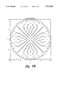
- FIG. 3A illustrates the calculated element positions for an elliptical ring geometry in accordance with a preferred embodiment of the invention.
- FIGS. 3B-3D show aspects of the power pattern for a discrete set of elements arranged in the elliptical pattern shown in FIG. 3A.
- FIG. 4 shows the process of sidelobe control by zero sampling in accordance with the present invention.
- FIGS. 5A-5C depict the layout of transducer elements in a sparse array for a circular aperture having 584, 428 and 280 elements, respectively, in accordance with the invention.
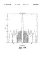
- FIGS. 6A-6C are graphs showing the power patterns for both narrowband and wideband operation of the transducer array shown in FIGS. 5A-5C.
- FIG. 6D is a graph showing the power pattern for narrowband operation for a fully populated circular aperture having 1256 elements.
- FIG. 7 is a graph comparing different power pattern cuts for a sparse transducer array of circular aperture with 428 transducer elements for wideband operation.
- FIG. 8 is a graph comparing the power patterns for wideband operation for a circular aperture for different degrees of thinning.
- FIG. 9 is a graph showing the performance for wideband operation of a sparse array and a fully populated array of a circular aperture with 428 elements.
- FIG. 10 is a typical pulse used for simulation.
- FIGS. 11A-11E depict the transducer element positions in a sparse array for an elliptical aperture having 476, 420, 368, 308 and 264 elements, respectively, in accordance with the invention.
- FIGS. 12A1-12E are graphs showing the power patterns for both narrowband and wideband operation of the transducer arrays shown in FIGS. 11A-11E respectively.
- FIG. 13 is a block diagram of an ultrasound imaging system incorporating a sparse transducer array in accordance with the invention.
- a circular aperture for two-dimensional steering
- a circular aperture would ideally be chosen to maximize the resolution for all angles, since resolution is roughly proportional to the inverse of the aperture size.
- the diameter of a circular array is too small.
- Typical one-dimensional ultrasound arrays have aperture widths of 50 ⁇ to 100 ⁇ , so that an aperture width of 14 ⁇ is not adequate. Hence there is a need for thinning or space tapering of transducer elements forming the aperture.
- the aperture width 2a is about 28 ⁇ , which is still inadequate for medical ultrasound imaging systems.
- One solution is to replace the circular aperture by an elliptical aperture, which allows increased resolution in one dimension at the expense of decreased resolution in the other.
- FIGS. 2A-2C show three geometries where the method can be applied.
- the source and field angles may be defined as ##EQU4## Further let
- the locations of elements on the ellipse are plotted from Eqs. (11a) and (11b) in FIG. 3A.
- the elements are spaced unequally along the ellipse.
- the corresponding response pattern along the x and y axes are plotted in FIG. 3B and 3C, respectively.
- FIG. 3D shows the contour pattern. It can be appreciated that the design method of the present invention produces a response pattern which has the symmetry of the array. This elliptical symmetry allows use of the zero sampling method for circular arrays disclosed in U.S. Pat. No. 5,515,060 with the modifications outlined below.
- Equation (12) is the solution for a single elliptical ring.
- a fully populated elliptical aperture which is discretized as a set of M concentric elliptical rings, where the m-th ring has a major axis a m and a minor axis b m .
- each ratio b m /a m be the same for all rings and let N m be the number of elements on the m-th ring.
- the response for the set of elliptical rings becomes ##EQU11##
- Equation (13) has the property that the sidelobes have the same elliptical symmetry as the array.
- Eq. (13) can be shown to be equivalent to the Taylor synthesis problem where the number of elements N m on the elliptical ring corresponds to the illumination on the m-th ring.
- R the ratio of the mainlobe power level to design sidelobe level. Typically R is 40 dB. If R is very large, the far sidelobes will deteriorate. Since far sidelobes are controlled by the total number of elements, an acceptable compromise value of R can be easily selected to keep the root-mean-square (RMS) value of the sidelobes nearly uniform.
- RMS root-mean-square
- FIGS. 5A-5C Three examples of thinning are shown in FIGS. 5A-5C.
- the thinned transducer array shown in FIG. 5A has 584 elements; that shown in FIG. 5B has 428 transducer elements; and that shown in FIG. 5C has 280 elements.
- Numerical simulations were performed to demonstrate applicability of the theory to broadband pulses which are typical of a medical ultrasound imaging system.
- the simulation was for a true time-delay beamformer, with a single focus range for simplicity.
- the time delay beamformer simulation employed a frequency of 5 MHz and a sampling frequency of 500 MHz.
- FIG. 10 illustrates a typical pulse used for the simulation.
- FIGS. 6A-6C For the thinned circular arrays shown in FIGS. 5A-5C, the corresponding patterns for various cuts are shown in FIGS. 6A-6C.
- the solid lines show performance at the center frequency (narrowband) and the dotted lines show the simulation results for pulsed operation to simulate ultrasound imaging (wideband).
- FIGS. 6A-6C can be compared with the pattern for a fully populated aperture having 1256 elements, shown in FIG. 6D.
- FIGS. 11A-11E depict the location of transducer elements in a sparse array for an elliptical aperture having 476, 420, 308, 308 and 264 elements, respectively.
- FIGS. 12A-12E show the power patterns for both narrowband and wideband operation of the transducer arrays shown in FIGS. 11A-11E.
- the solid lines represent performance for narrowband operation and the dotted lines represent performance for wideband operation. Again it is apparent that the sidelobes are well-controlled.
- thinned two-dimensional arrays of transducer elements can be designed for use in ultrasound imaging systems.
- the design method of the invention can be applied to a variety of shapes consisting of self-similar geometric curves (see FIG. 2).
- thinning is accomplished with sidelobe control.
- the design controls the near-in sidelobes, suppresses average sidelobes to a low level, and accomplishes thinning in the neighborhood of 50% or greater, without any appreciable degradation of the whole pattern and controlled sidelobes.
- a simple algorithm can be used to move each calculated element location to the nearest grid point. Elements which would be moved to a grid point which is already occupied are deleted. The shifting of elements to the nearest grid locations and deletion of duplicate elements causes small perturbations in the array response, but these will not cause any significant deterioration in the sidelobe control.
- the invention is not limited to geometries in which the rings are equally spaced.
- a designer would need to find the number of elements on each ring as well as to locate the position of the ring.
- This procedure can be done by an iterative process in which a set of ring locations is assumed; then after proceeding as indicated hereinabove, iterations around the assumed locations of the rings are performed by Newton's method.
- a sparse transducer array is incorporated in an ultrasound imaging system.
- Such imaging system is depicted in FIG. 13 and includes a transducer array 10 comprised of a plurality of separately driven transducer elements 12, each of which produces a burst of ultrasonic energy when energized by a pulsed waveform produced by a transmitter 22.
- the ultrasonic energy reflected back to transducer array 10 from the object under study is converted to an electrical signal by each receiving transducer element 12 and applied separately to a receiver 24 through a set of transmit/receive (T/R) switches 26.
- Transmitter 22, receiver 24 and switches 26 are operated under control of a digital controller 28 responsive to commands by a human operator.
- a complete scan is performed by acquiring a series of echoes in which switches 26 are set to their transmit positions, transmitter 22 is gated ON momentarily to energize each transducer element 12, switches 26 are then set to their receive positions, and the subsequent echo signals detected by each transducer element 12 are applied to receiver 24, which combines the separate echo signals from each transducer element to produce a single echo signal which is used to produce a line in an image on a display monitor 30.
- Transmitter 22 drives transducer array 10 such that the ultrasonic energy produced is directed, or steered, in a beam.
- transmitter 22 imparts a time delay T i to the respective pulsed waveforms 34 that are applied to successive transducer elements 12.
- T i By adjusting the time delays T i appropriately in a conventional manner, the ultrasonic beam can be directed away from axis 36 by angles ⁇ and ⁇ and/or focused at a fixed range R.
- a sector scan is performed by progressively changing the time delays T i in successive excitations. The angles ⁇ and ⁇ are thus changed in increments to steer the transmitted beam in a succession of directions.
- the echo signals produced by each burst of ultrasonic energy reflect from objects located at successive ranges along the ultrasonic beam.
- the echo signals are sensed separately by each transducer element 12 and a sample of the magnitude of the echo signal at a particular point in time represents the amount of reflection occurring at a specific range. Due to the differences in the propagation paths between a reflecting point P and each transducer element 12, however, these echo signals will not be detected simultaneously and their amplitudes will not be equal.
- Receiver 24 amplifies the separate echo signals, imparts the proper time delay to each, and sums them to provide a single echo signal which accurately indicates the total ultrasonic energy reflected from point P located at range R along the ultrasonic beam oriented at the angles ⁇ and ⁇ .
Abstract
An ultrasonic imaging system employs a thinned array of transducer elements in order to reduce the number of signal processing channels. The transducer elements are reduced in number and then selectively located at grid positions in a pattern which reduces the sidelobe levels produced by the array. Thinning is accomplished by discretizing the aperture of the transducer array in two steps. First, a continuous aperture is discretized as a set of concentric rings. Then each ring is replaced by a set of spaced transducer elements. A zero sampling technique is used to determine the number of elements on each ring.
Description
This invention relates to medical ultrasound imaging systems having a two-dimensional array of ultrasound transducers, and more particularly, to sparse two-dimensional arrays steerable in azimuth and elevation directions.
Conventional ultrasound imaging systems comprise an array of ultrasound transducer elements which transmit an ultrasound beam and receive the reflected beam from the object being studied. For medical ultrasound imaging, the array typically has a multiplicity of transducer elements arranged in a line and driven with separate voltages. By selecting the time delay (or phase) and amplitude of the applied voltages, the individual transducer elements can be controlled to produce ultrasonic waves which combine to form a net ultrasonic wave that travels along a preferred vector direction and is focused at a selected point along the beam. Multiple firings may be used to acquire data representing the same anatomical information. The beamforming parameters of each of the firings may be varied to provide a change in maximum focus or otherwise change the content of the received data for each firing, e.g., by transmitting successive beams along the same scan line with the focal point of each beam being shifted relative to the focal point of the previous beam. By changing the time delay and amplitude of the applied voltages, the beam with its focal point can be moved to scan the object.
The same principles apply when the transducer probe is employed to receive the reflected sound in a receive mode. The voltages produced at the receiving transducer elements are summed so that the net signal is indicative of the ultrasound energy reflected from a single focal point in the object. As with the transmission mode, this focused reception of the ultrasonic energy is achieved by imparting separate time delays (and/or phase shifts) and gains to the signal from each receiving transducer element.
Such scanning comprises a series of measurements in which the steered ultrasonic wave is transmitted, the system switches to receive mode after a short time interval, and the reflected ultrasonic wave is received and stored. Typically, transmission and reception are steered in the same direction during each measurement to acquire data from a series of points along an acoustic beam or scan line. The receiver is dynamically focused at a succession of ranges along the scan line as the reflected ultrasonic waves are received.
Ultrasonic imaging systems are known in which each transducer element is served by an individual analog channel followed by an analog-to-digital converter and one delay chip. Thus, a 128-channel system requires 128 delay chips and all of their associated memory and bus components. The delay chips introduce the time delays required for time delay beamforming. In the receive mode, the signals from all of the transducer elements are time delayed and then summed to form the summed signal representing all of the reflections from a point located at the desired range and steering angle.
It is widely accepted that a two-dimensional array would be advantageous in medical ultrasound imaging. Such an array would be steerable in both the azimuth and elevation directions. One of the limitations on the practicality of two-dimensional arrays is the electronic channel count. Simple brute force extension of conventional systems to such large systems is not practical. Increasing the number of connections to the transducer elements through the coaxial cable to the probe becomes prohibitive. Increasing the electronics of conventional beamforming systems by a factor of four or eight would be expensive and excessively power consuming. By duplexing, it is possible to double the number of effective channels; however, there is a need for further reduction in the number of channels needed to achieve a practical two-dimensional array.
The appearance of landmark papers by T. T. Taylor on the synthesis of linear and circular apertures (in 1955 and 1960) has revolutionized the design procedures for many radars of linear, rectangular or circular apertures which need sidelobe controls. Radar engineers find it fairly routine to incorporate Taylor synthesis in their designs. The Taylor method provides a nearly ideal pattern for realizable illumination of the aperture, and removes the deficiencies of classical Chebyshev arrays. Further, the method has found application in related fields, e.g., pulse compression or filter design, where windowing is essential. The success of the method is due primarily to simplicity of the procedure. The design engineer does not need to investigate the exact mathematical foundation on which the theory is based. It is such precise mathematical analysis that has led to the success of this theory, which uses special functions and asymptotic analysis.
Elliptical apertures and the corresponding analysis have not received great attention despite the wide potential application of elliptical aperture synthesis in modern radar applications, modern communication applications and reflector antennas. This may be due to the unavailability of simple design procedures for synthesis of elliptical arrays or apertures.
Taylor synthesis is outlined in radar handbooks. Advanced books on antenna and radar describe Taylor synthesis for linear arrays as well as for circular arrays to various degrees of sophistication. Some literature for the design of reflectors for communication with projected elliptical shape for earth coverage has appeared. Taylor synthesis can be extended to reduce the number of electrical channels while increasing performance, thereby enhancing imaging capability without additional hardware.
The invention is an ultrasonic imaging system with a sparse array of transducer elements steerable in two dimensions. The elements are located at selected positions on a regular grid in such a way as to reduce the sidelobe levels produced by the array. The selective location of the transducer elements is hereinafter referred to as "space tapering." The term "space tapering" refers to a deterministic or selective, as opposed to random, placement. The sparse population of the grid positions reduces the number of electronic channels needed to process the signal to and from the transducer elements. The decrease in the population of transducer elements relative to the grid is hereinafter referred to as "thinning." The thinning and space-tapering is accomplished by a flexible, rapid procedure which optimizes the array for all steering angles.
The aperture of the transducer array is discretized into a grid in two steps. First, a continuous aperture is discretized as a set of concentric rings. Next each ring is replaced by a set of transducer elements. To determine the number of elements on each ring, a technique of zero sampling is used.
The array design of the invention is based on analytic solutions of aperture integral equations. Sidelobe control is achieved by controlling the illumination of the aperture. This illumination ultimately corresponds to the density of the elements in the sparse array, with each element of the array having uniform amplitude for maximum efficiency or signal-to-noise ratio. The design goal is to produce sidelobes which are uniform around the main beam and decay asymptotically. Space tapering is accomplished in a manner which improves the sidelobe level relative to that of the fully populated array.
Another aspect of the invention is that the array design is valid for wideband operation centered on the design center frequency. The sidelobe performance does not deteriorate when a pulsed signal is used for ultrasound imaging and, in some cases, is enhanced thereby.
FIG. 1 illustrates the spherical coordinates adopted for the calculations that aid in understanding the invention.
FIGS. 2A-2C illustrates three noncircular aperture geometries other than elliptical that can be analyzed in accordance with the invention.
FIG. 3A illustrates the calculated element positions for an elliptical ring geometry in accordance with a preferred embodiment of the invention.
FIGS. 3B-3D show aspects of the power pattern for a discrete set of elements arranged in the elliptical pattern shown in FIG. 3A.
FIG. 4 shows the process of sidelobe control by zero sampling in accordance with the present invention.
FIGS. 5A-5C depict the layout of transducer elements in a sparse array for a circular aperture having 584, 428 and 280 elements, respectively, in accordance with the invention.
FIGS. 6A-6C are graphs showing the power patterns for both narrowband and wideband operation of the transducer array shown in FIGS. 5A-5C.
FIG. 6D is a graph showing the power pattern for narrowband operation for a fully populated circular aperture having 1256 elements.
FIG. 7 is a graph comparing different power pattern cuts for a sparse transducer array of circular aperture with 428 transducer elements for wideband operation.
FIG. 8 is a graph comparing the power patterns for wideband operation for a circular aperture for different degrees of thinning.
FIG. 9 is a graph showing the performance for wideband operation of a sparse array and a fully populated array of a circular aperture with 428 elements.
FIG. 10 is a typical pulse used for simulation.
FIGS. 11A-11E depict the transducer element positions in a sparse array for an elliptical aperture having 476, 420, 368, 308 and 264 elements, respectively, in accordance with the invention.
FIGS. 12A1-12E are graphs showing the power patterns for both narrowband and wideband operation of the transducer arrays shown in FIGS. 11A-11E respectively.
FIG. 13 is a block diagram of an ultrasound imaging system incorporating a sparse transducer array in accordance with the invention.
Although the following description relates to methods for thinning and space tapering ultrasound arrays having circular and elliptical apertures it will be appreciated that the invention has application to apertures of geometries other than circles and ellipses.
In an ultrasound imaging system employing a large number of transducer elements, a circular aperture (for two-dimensional steering) would ideally be chosen to maximize the resolution for all angles, since resolution is roughly proportional to the inverse of the aperture size. But for a reasonable number of elements, the diameter of a circular array is too small. The relationship between the number of elements N and the diameter 2a of a circular probe is given by ##EQU1## where λ is the ultrasound wavelength, and the area of each element is (λ/2)2. If N=512, then 2a is about 14λ. Typical one-dimensional ultrasound arrays have aperture widths of 50λ to 100λ, so that an aperture width of 14λ is not adequate. Hence there is a need for thinning or space tapering of transducer elements forming the aperture.
If the aforementioned circular aperture is thinned by 75%, i.e., only every fourth location on a rectangular grid is populated by a transducer element (as opposed to a fully-populated grid wherein each grid point is occupied by a transducer element), then the aperture width 2a is about 28λ, which is still inadequate for medical ultrasound imaging systems.
One solution is to replace the circular aperture by an elliptical aperture, which allows increased resolution in one dimension at the expense of decreased resolution in the other. The area of an ellipse with width 2a and height 2b is πab. If we choose, for example, an aspect ratio b/a=1/4, then the area of such an ellipse (πa2 /4) is one-fourth the area of a circle whose diameter is the width of the ellipse. Since the number of elements required to fully populate an array is proportional to the area of the array, such an elliptical array requires only one-fourth as many elements as the corresponding circular array. Alternately, for the same number of elements, such an elliptical array would be √4=2 times wider than the corresponding circular array (but with half the height). For the example above with 75% thinning and 512 elements, this elliptical array would have width of about 52λ. This example, although trivial, illustrates the need for thinning--if possible, to a circular array or, in the alternative, to an elliptical array.
In accordance with phased array theory, consider N transducer elements located at xn, yn (n=1, . . . , N) along a closed curve, for example, an ellipse. Assume that each element has unit illumination. In the event of an incoming ultrasound beam impinging on the array from the direction (θ, φ) as shown in FIG. 1, with the center frequency wavelength λ, the array response is given by ##EQU2## where the field quantities are given by Tx =sin θ cos φ and Ty =sin θ sin φ. For simplicity of presentation, the invariant transformation described in detail by T. Y. Lo and H. C. Hsuan, "An equivalence theory between elliptical and circular arrays," IEEE Trans. Antennas and Propagation, March 1965, pp. 247-253, will be used. This theory enables solutions for a wide variety of geometries to be obtained by mapping them onto a circle. It can be seen from Eq. (2) that the response E(θ, φ) remains invariant if
T.sub.x x.sub.n +T.sub.y y.sub.n =T'.sub.x x'.sub.n +T'.sub.y y'.sub.n (3)
where unprimed and primed quantities correspond to the actual and circular geometry respectively. To illustrate the method, consider an elliptical geometry with a, b as the major and minor axes, respectively, mapped onto a circular geometry. The method, however, is quite general and can be used to analyze any geometry as long as it can be mapped onto a circle. FIGS. 2A-2C show three geometries where the method can be applied.
The left-hand side of Eq. (3) may be rewritten in matrix form as ##EQU3## where τ=1t=a/b, and hence the inner matrix product in Eq. (4) is an identity matrix.
From the right-hand side of Eq. (3) and comparing with Eq. (4), for the invariance the transformation is
x'.sub.n x.sub.n
y'.sub.n =τy.sub.n
T'.sub.x =T.sub.x
T'.sub.y =T.sub.y (5)
The source and field angles may be defined as ##EQU4## Further let
x'.sub.n a cosΦ'.sub.n
y'.sub.n =a sin Φ'.sub.n
T'.sub.x R'cosφ'
T'.sub.y =R'sinφ'
where ##EQU5## Hence Eq. (3) becomes ##EQU6## where κ2 =1-t2 =(1-b2 /a2. Hence Eq. (2) becomes ##EQU7##
If the elements are located in such a way that their angular positions in the transformed plane are equally spaced, then their angular positions Φn in untransformed coordinates are ##EQU8## where n=1, . . . , N. The element locations are then given by ##EQU9## If the number of elements N is large and Eqs. 10, 11a and 16 are true, then Eq. (9) can be approximated by ##EQU10## where Jo (x) is the Bessel function of order zero.
For illustration, the locations of elements on the ellipse are plotted from Eqs. (11a) and (11b) in FIG. 3A. As can be seen in FIG. 3A, the elements are spaced unequally along the ellipse. The corresponding response pattern along the x and y axes are plotted in FIG. 3B and 3C, respectively. FIG. 3D shows the contour pattern. It can be appreciated that the design method of the present invention produces a response pattern which has the symmetry of the array. This elliptical symmetry allows use of the zero sampling method for circular arrays disclosed in U.S. Pat. No. 5,515,060 with the modifications outlined below.
Equation (12) is the solution for a single elliptical ring. Consider a fully populated elliptical aperture which is discretized as a set of M concentric elliptical rings, where the m-th ring has a major axis am and a minor axis bm. Further, let each ratio bm /am be the same for all rings and let Nm be the number of elements on the m-th ring. Then from Eq. (12), the response for the set of elliptical rings becomes ##EQU11## The objective is to find Nm (m=1, . . . , M), the number of elements in the m-th ring. Equation (13) has the property that the sidelobes have the same elliptical symmetry as the array. Hence for a fixed φ=φ0, Eq. (13) can be shown to be equivalent to the Taylor synthesis problem where the number of elements Nm on the elliptical ring corresponds to the illumination on the m-th ring. The idea of zero sampling for a φ=φ0 cut is illustrated schematically in FIG. 4. Since the Taylor method is well known, for simplicity the stretched zeros of Taylor analysis are used. The method can be explained as follows. First select the number of the rings M. M is usually twice the aperture radius in units of wavelengths. Then select n, the number of sidelobes to be controlled. Typically n is 6 to 8. Select R, the ratio of the mainlobe power level to design sidelobe level. Typically R is 40 dB. If R is very large, the far sidelobes will deteriorate. Since far sidelobes are controlled by the total number of elements, an acceptable compromise value of R can be easily selected to keep the root-mean-square (RMS) value of the sidelobes nearly uniform. Compute A from ##EQU12## The stretching parameter for the near-in zeros of the pattern is ##EQU13## where μi is the i-th zero of the first derivative of the Bessel function of order zero. The Taylor zeros are given by ##EQU14## for i=1, . . . , n-1, and
ω.sub.i μ.sub.i (17)
for i=n, . . . , M-1. Define a function g ##EQU15## where aM is the major axis of the aperture. The function g will be recognized as part of the argument of the Bessel function in Eq. (13). It will be appreciated that Eq. (18) would be substantially different for a circular aperture. This function must be modified for different geometries.
Defining the non-dimensional radius am /aM =γM, Eq. (13) may be rewritten as follows: ##EQU16## Form the following set of M-1 homogeneous equations by substituting g=ωi, for i=1, . . . , M-1, and setting E(θ, φ) equal to zero:
O=N.sub.1 J.sub.0 (πω.sub.i γ.sub.1)+N.sub.2 J.sub.0 (πω.sub.i γ.sub.2)+. . . +N.sub.M J.sub.0 (πω.sub.i γ.sub.M) (20)
where i=1, . . . , M-1. Moving the first term on the right to the left side and dividing both sides by N1, the number of elements on the first ring, the following set of equations is obtained: ##EQU17## These (M-1) equations are solved for the ratios N2 /N1, N3 /N1, . . . , and NM /N1. The value N1 is determined by the total number of desired elements in the array, ##EQU18## Each Nm must then be rounded to the nearest integer value.
Based on the above algorithm, three examples of thinning are shown in FIGS. 5A-5C. The thinned transducer array shown in FIG. 5A has 584 elements; that shown in FIG. 5B has 428 transducer elements; and that shown in FIG. 5C has 280 elements.
The foregoing analysis was performed at a single frequency, i.e., a single λ. The rings were spaced at 1/2λ intervals. In practice, λ is taken to be the wavelength at the center frequency. The analysis only involves amplitude control, corresponding to the number of elements located on each ring; no phases were perturbed or controlled. Hence except for the spacing, the above analysis is nearly independent of frequency. Simulation shows that the sidelobe property of space tapering is still maintained under a very wideband operation.
Numerical simulations were performed to demonstrate applicability of the theory to broadband pulses which are typical of a medical ultrasound imaging system. The simulation was for a true time-delay beamformer, with a single focus range for simplicity. The time delay beamformer simulation employed a frequency of 5 MHz and a sampling frequency of 500 MHz. FIG. 10 illustrates a typical pulse used for the simulation.
For the thinned circular arrays shown in FIGS. 5A-5C, the corresponding patterns for various cuts are shown in FIGS. 6A-6C. The solid lines show performance at the center frequency (narrowband) and the dotted lines show the simulation results for pulsed operation to simulate ultrasound imaging (wideband). The cuts are made at φ=0° (FIG. 6A), 30° (FIG. 6B) and 45° (FIG. 6C). It can be seen that under both conditions, sidelobes are well below -20 dB. FIGS. 6A-6C can be compared with the pattern for a fully populated aperture having 1256 elements, shown in FIG. 6D.
FIG. 7 compares different power pattern cuts for wideband operation for a sparse transducer array of circular aperture having 428 elements. The cuts are made at φ=0° (dotted line), 45° (solid line) and 60°.
FIG. 8 compares wideband power patterns for a circular aperture with thinning; 584 (solid line), 428 (dash-dot line) and 280 elements (dotted line). The cuts are made at (φ=0° for 584 elements and 45° for 280 and 428 elements.
FIG. 9 is a graph showing the power patterns of a sparse array of circular aperture with 428 elements (dotted line) and a fully populated array (solid line). The cuts are made at φ=0° for both arrays.
FIGS. 11A-11E depict the location of transducer elements in a sparse array for an elliptical aperture having 476, 420, 308, 308 and 264 elements, respectively. FIGS. 12A-12E show the power patterns for both narrowband and wideband operation of the transducer arrays shown in FIGS. 11A-11E. The solid lines represent performance for narrowband operation and the dotted lines represent performance for wideband operation. Again it is apparent that the sidelobes are well-controlled.
Using the foregoing procedures, thinned two-dimensional arrays of transducer elements can be designed for use in ultrasound imaging systems. The design method of the invention can be applied to a variety of shapes consisting of self-similar geometric curves (see FIG. 2). In accordance with the invention, thinning is accomplished with sidelobe control. The design controls the near-in sidelobes, suppresses average sidelobes to a low level, and accomplishes thinning in the neighborhood of 50% or greater, without any appreciable degradation of the whole pattern and controlled sidelobes.
The procedure for designing an ultrasound imaging transducer, and the equations to be used, are summarized as follows:
(1) Select major and minor axes of the aperture to be designed. For a circular aperture, the major and minor axes are the same. This will provide the value of M, the number of rings.
(2) Select a desired sidelobe ratio R and compute A from Eq. (14).
(3) Select n and compute σ and ωi from Eqs. (15), (16) and (17).
(4) Solve Eqs. (21), select N1 and compute Nm, m=2, . . . , M, such that ##EQU19## is the desired number of elements in the array.
(5) Once the Nm are determined, use Eqs. (10), (11a) and (11b) to determine the locations of the elements on each circular or elliptical ring.
(6) Move the element locations onto a regular grid.
A simple algorithm can be used to move each calculated element location to the nearest grid point. Elements which would be moved to a grid point which is already occupied are deleted. The shifting of elements to the nearest grid locations and deletion of duplicate elements causes small perturbations in the array response, but these will not cause any significant deterioration in the sidelobe control.
The invention is not limited to geometries in which the rings are equally spaced. For a general thinning and space tapering method, a designer would need to find the number of elements on each ring as well as to locate the position of the ring. This procedure can be done by an iterative process in which a set of ring locations is assumed; then after proceeding as indicated hereinabove, iterations around the assumed locations of the rings are performed by Newton's method.
In accordance with the invention, a sparse transducer array is incorporated in an ultrasound imaging system. Such imaging system is depicted in FIG. 13 and includes a transducer array 10 comprised of a plurality of separately driven transducer elements 12, each of which produces a burst of ultrasonic energy when energized by a pulsed waveform produced by a transmitter 22. The ultrasonic energy reflected back to transducer array 10 from the object under study is converted to an electrical signal by each receiving transducer element 12 and applied separately to a receiver 24 through a set of transmit/receive (T/R) switches 26. Transmitter 22, receiver 24 and switches 26 are operated under control of a digital controller 28 responsive to commands by a human operator. A complete scan is performed by acquiring a series of echoes in which switches 26 are set to their transmit positions, transmitter 22 is gated ON momentarily to energize each transducer element 12, switches 26 are then set to their receive positions, and the subsequent echo signals detected by each transducer element 12 are applied to receiver 24, which combines the separate echo signals from each transducer element to produce a single echo signal which is used to produce a line in an image on a display monitor 30.
The echo signals produced by each burst of ultrasonic energy reflect from objects located at successive ranges along the ultrasonic beam. The echo signals are sensed separately by each transducer element 12 and a sample of the magnitude of the echo signal at a particular point in time represents the amount of reflection occurring at a specific range. Due to the differences in the propagation paths between a reflecting point P and each transducer element 12, however, these echo signals will not be detected simultaneously and their amplitudes will not be equal. Receiver 24 amplifies the separate echo signals, imparts the proper time delay to each, and sums them to provide a single echo signal which accurately indicates the total ultrasonic energy reflected from point P located at range R along the ultrasonic beam oriented at the angles θ and φ.
While only certain preferred features of the invention have been illustrated and described, many modifications and changes will occur to those skilled in the art. It is, therefore, to be understood that the appended claims are intended to cover all such modifications and changes as fall within the true spirit of the invention.
Claims (12)
1. An ultrasound imaging system comprising:
an ultrasound transducer array comprising a grid having a predetermined number of grid points and a plurality of ultrasound transducer elements supported by said grid, each of said transducer elements being located at a respective grid point in a set of grid points selected to be located in a predetermined pattern so that an aperture of said array has smaller sidelobe levels than would be produced by a fully populated grid, the number of ultrasound transducer elements being less than said predetermined number;
transmitter means for activating said ultrasound transducer elements to transmit a series of transmit ultrasound waveforms;
beamforming means for forming receive beams from signals provided by said ultrasound transducer elements in response to reception of ultrasound energy from a reflecting point on which said transmit ultrasound waveforms impinge; and
monitoring means for displaying an image which is a function of said receive beams.
2. The ultrasound imaging system of claim 1 wherein said predetermined pattern is symmetrical relative to a first axis of said aperture.
3. The ultrasound imaging system of claim 2 wherein said predetermined pattern is symmetrical relative to a second axis of said aperture perpendicular to said first axis.
4. The ultrasound imaging system of claim 1 wherein said aperture is generally circular in shape.
5. The ultrasound imaging system of claim 4, wherein each of said set of grid points is closest to a respective one of a set of calculated transducer locations, said set of calculated transducer locations comprising a plurality of subsets of calculated transducer locations, each of said subsets comprising a respective number of calculated transducer locations spaced along a respective one of a plurality of concentric circles.
6. The ultrasound imaging system of claim 1 wherein said aperture is generally elliptical in shape.
7. The ultrasound imaging system of claim 6 wherein each of said set of grid points is closest to a respective one of a set of calculated transducer locations, said set of calculated transducer locations comprising a plurality of subsets of calculated transducer locations, each of said subsets comprising a respective number of calculated transducer locations spaced along a respective one of a plurality of concentric elliptical rings.
8. An ultrasound transducer array for medical imaging, comprising:
a grid having a predetermined number of grid points; and
a plurality of ultrasound transducers supported by said grid, each of said transducers being located at a respective grid point in a set of grid points arranged to form a non-circular aperture, the number of ultrasound transducers being less than said predetermined number,
wherein the grid points of said set are located in a predetermined pattern so that said non-circular aperture of said array has smaller sidelobe levels than would be produced by a fully populated grid coextensive with said non-circular aperture.
9. The ultrasound transducer array of claim 8 wherein said predetermined pattern is symmetrical relative to a first axis of said aperture.
10. The ultrasound transducer array of claim 9 wherein said predetermined pattern is symmetrical relative to a second axis of said aperture perpendicular to said first axis.
11. The ultrasound transducer array of claim 8 wherein said non-circular aperture is generally elliptical in shape.
12. The ultrasound transducer array of claim 11 wherein each of said set of grid points is closest to a respective one of a set of calculated transducer locations, said set of calculated transducer locations comprising a plurality of subsets of calculated transducer locations, each of said subsets comprising a respective number of calculated transducer locations spaced along a respective one of a plurality of concentric elliptical rings.
Priority Applications (1)
| Application Number | Priority Date | Filing Date | Title |
|---|---|---|---|
| US09/010,046 US5911692A (en) | 1998-01-20 | 1998-01-20 | Sparse two-dimensional wideband ultrasound transducer arrays |
Applications Claiming Priority (1)
| Application Number | Priority Date | Filing Date | Title |
|---|---|---|---|
| US09/010,046 US5911692A (en) | 1998-01-20 | 1998-01-20 | Sparse two-dimensional wideband ultrasound transducer arrays |
Publications (1)
| Publication Number | Publication Date |
|---|---|
| US5911692A true US5911692A (en) | 1999-06-15 |
Family
ID=21743537
Family Applications (1)
| Application Number | Title | Priority Date | Filing Date |
|---|---|---|---|
| US09/010,046 Expired - Fee Related US5911692A (en) | 1998-01-20 | 1998-01-20 | Sparse two-dimensional wideband ultrasound transducer arrays |
Country Status (1)
| Country | Link |
|---|---|
| US (1) | US5911692A (en) |
Cited By (65)
| Publication number | Priority date | Publication date | Assignee | Title |
|---|---|---|---|---|
| US6221022B1 (en) * | 2000-04-03 | 2001-04-24 | G.E. Medical Systems Global Technology Company Llc | Multiple transmit scanning to increase ultrasonic frame rate |
| US6238346B1 (en) * | 1999-06-25 | 2001-05-29 | Agilent Technologies, Inc. | System and method employing two dimensional ultrasound array for wide field of view imaging |
| US20030220554A1 (en) * | 2002-05-23 | 2003-11-27 | Volumetrics Medical Imaging, Inc. | Two-dimensional ultrasonic array with asymmetric apertures |
| FR2841342A1 (en) * | 2002-06-21 | 2003-12-26 | Thales Ultrasonics Sas | INPUT STRUCTURE FOR ULTRASOUND ECHOGRAPHY |
| US6682483B1 (en) * | 1999-05-28 | 2004-01-27 | Vuesonix Sensors, Inc. | Device and method for mapping and tracking blood flow and determining parameters of blood flow |
| US6682488B2 (en) * | 2001-04-12 | 2004-01-27 | Vuesinx Sensors, Inc. | Ultrasound probe with progressive element sizing |
| US20040019278A1 (en) * | 2000-05-26 | 2004-01-29 | Kenneth Abend | Device and method for mapping and tracking blood flow and determining parameters of blood flow |
| US20040122316A1 (en) * | 2002-09-30 | 2004-06-24 | Fuji Photo Film Co., Ltd. | Ultrasonic transmitting and receiving apparatus and ultrasonic transmitting and receiving method |
| US20040220474A1 (en) * | 2002-03-20 | 2004-11-04 | Kenneth Abend | Determining the power of an ultrasound reflection using an autocorrelation technique |
| US20040254468A1 (en) * | 2003-03-27 | 2004-12-16 | Vuesonix Sensors, Inc. | Mapping and tracking blood flow using reduced-element probe |
| US20040254461A1 (en) * | 2002-03-20 | 2004-12-16 | Ackerman William H. | Acoustic beam shaping by pulse power modulation at constant amplitude |
| US20040264707A1 (en) * | 2001-08-31 | 2004-12-30 | Jun Yang | Steering of directional sound beams |
| US20040267127A1 (en) * | 1999-05-28 | 2004-12-30 | Vuesonix Sensors, Inc. | Transmitter patterns for multi beam reception |
| US20050004461A1 (en) * | 1999-05-28 | 2005-01-06 | Kenneth Abend | Pulse interleaving in doppler ultrasound imaging |
| US20050004464A1 (en) * | 2003-03-14 | 2005-01-06 | Vuesonix Sensors, Inc. | Method and apparatus for forming multiple beams |
| US20050004468A1 (en) * | 2003-03-17 | 2005-01-06 | Vuesonix Sensors, Inc. | Increased sensitivity for 4-D ultrasound imaging and for 4-D doppler ultrasound imaging |
| US20050033182A1 (en) * | 2003-07-01 | 2005-02-10 | Marino Cerofolini | Electronic array probe for ultrasonic imaging |
| US20050124885A1 (en) * | 2003-10-29 | 2005-06-09 | Vuesonix Sensors, Inc. | Method and apparatus for determining an ultrasound fluid flow centerline |
| US20080009739A1 (en) * | 2006-06-23 | 2008-01-10 | Chiang Alice M | Ultrasound 3D imaging system |
| US20090270735A1 (en) * | 2003-07-01 | 2009-10-29 | Esaote, S.P.A. | Electronic array probe for ultrasonic imaging |
| US20100152587A1 (en) * | 2008-12-17 | 2010-06-17 | General Electric Company | Systems and methods for operating a two-dimensional transducer array |
| US20100174194A1 (en) * | 2008-09-15 | 2010-07-08 | Teratech Corporation | Ultrasound 3d imaging system |
| US20100274136A1 (en) * | 2009-04-23 | 2010-10-28 | Marino Cerofolini | Array of electroacoustic transducers and electronic probe for three-dimensional imaging |
| US20110301467A1 (en) * | 2010-06-04 | 2011-12-08 | Toshiba Medical Systems Corporation | Medical ultrasound 2-d transducer array architecture: spot of arago |
| US20120289835A1 (en) * | 2009-11-09 | 2012-11-15 | Sonosite, Inc. | Systems and methods for beam enhancement |
| CN103116162A (en) * | 2012-12-14 | 2013-05-22 | 西安电子科技大学 | High-resolution sonar location method based on sparsity of objective space |
| NL2008725C2 (en) * | 2012-04-27 | 2013-10-29 | Univ Delft Tech | A transducer array of an imaging system. |
| CN103792288A (en) * | 2014-01-28 | 2014-05-14 | 河海大学 | Sparse array ultrasound phased array detection method of concrete dam disease |
| US8866686B1 (en) | 2009-03-25 | 2014-10-21 | Raytheon Company | Methods and apparatus for super-element phased array radiator |
| US8907842B1 (en) | 2009-03-25 | 2014-12-09 | Raytheon Company | Method and apparatus for attenuating a transmitted feedthrough signal |
| US20150369909A1 (en) * | 2014-06-19 | 2015-12-24 | Imperium, Inc. | Image sensor for large area ultrasound mapping |
| US9373888B1 (en) | 2009-03-25 | 2016-06-21 | Raytheon Company | Method and apparatus for reducing sidelobes in large phased array radar with super-elements |
| US9379446B1 (en) | 2013-05-01 | 2016-06-28 | Raytheon Company | Methods and apparatus for dual polarized super-element phased array radiator |
| WO2019005487A1 (en) * | 2017-06-28 | 2019-01-03 | Invensense, Inc. | Image generation in an electronic device using ultrasonic transducers |
| CN109350112A (en) * | 2018-11-13 | 2019-02-19 | 飞依诺科技(苏州)有限公司 | Ultrasonic image imaging method and device and medical equipment |
| US10281571B2 (en) | 2014-08-21 | 2019-05-07 | Raytheon Company | Phased array antenna using stacked beams in elevation and azimuth |
| US10426435B2 (en) | 2008-09-15 | 2019-10-01 | Teratech Corporation | Ultrasound 3D imaging system |
| US10670716B2 (en) | 2016-05-04 | 2020-06-02 | Invensense, Inc. | Operating a two-dimensional array of ultrasonic transducers |
| US10706835B2 (en) | 2016-05-10 | 2020-07-07 | Invensense, Inc. | Transmit beamforming of a two-dimensional array of ultrasonic transducers |
| US10755067B2 (en) | 2018-03-22 | 2020-08-25 | Invensense, Inc. | Operating a fingerprint sensor comprised of ultrasonic transducers |
| US10860831B2 (en) | 2017-06-01 | 2020-12-08 | Invensense, Inc. | Image generation in an electronic device using ultrasonic transducers |
| CN112347696A (en) * | 2020-11-06 | 2021-02-09 | 中国电子科技集团公司第三十八研究所 | Discretization area scanning subarray-level sparse optimization method and system |
| US10936841B2 (en) | 2017-12-01 | 2021-03-02 | Invensense, Inc. | Darkfield tracking |
| US10936843B2 (en) | 2018-12-28 | 2021-03-02 | Invensense, Inc. | Segmented image acquisition |
| US10984209B2 (en) | 2017-12-01 | 2021-04-20 | Invensense, Inc. | Darkfield modeling |
| US10997388B2 (en) | 2017-12-01 | 2021-05-04 | Invensense, Inc. | Darkfield contamination detection |
| US11112388B2 (en) | 2016-05-10 | 2021-09-07 | Invensense, Inc. | Operation of an ultrasonic sensor |
| US11151355B2 (en) | 2018-01-24 | 2021-10-19 | Invensense, Inc. | Generation of an estimated fingerprint |
| US11154906B2 (en) | 2016-05-10 | 2021-10-26 | Invensense, Inc. | Receive operation of an ultrasonic sensor |
| US11176345B2 (en) | 2019-07-17 | 2021-11-16 | Invensense, Inc. | Ultrasonic fingerprint sensor with a contact layer of non-uniform thickness |
| US11188735B2 (en) | 2019-06-24 | 2021-11-30 | Invensense, Inc. | Fake finger detection using ridge features |
| US11216681B2 (en) | 2019-06-25 | 2022-01-04 | Invensense, Inc. | Fake finger detection based on transient features |
| US11216632B2 (en) | 2019-07-17 | 2022-01-04 | Invensense, Inc. | Ultrasonic fingerprint sensor with a contact layer of non-uniform thickness |
| US11224410B2 (en) * | 2017-04-24 | 2022-01-18 | Koninklijke Philips N.V. | Methods and systems for filtering ultrasound image clutter |
| US11232549B2 (en) | 2019-08-23 | 2022-01-25 | Invensense, Inc. | Adapting a quality threshold for a fingerprint image |
| US11243300B2 (en) | 2020-03-10 | 2022-02-08 | Invensense, Inc. | Operating a fingerprint sensor comprised of ultrasonic transducers and a presence sensor |
| US11288891B2 (en) | 2016-05-10 | 2022-03-29 | Invensense, Inc. | Operating a fingerprint sensor comprised of ultrasonic transducers |
| US11328165B2 (en) | 2020-04-24 | 2022-05-10 | Invensense, Inc. | Pressure-based activation of fingerprint spoof detection |
| US11392789B2 (en) | 2019-10-21 | 2022-07-19 | Invensense, Inc. | Fingerprint authentication using a synthetic enrollment image |
| US11440052B2 (en) | 2016-05-04 | 2022-09-13 | Invensense, Inc. | Two-dimensional array of CMOS control elements |
| US11460957B2 (en) | 2020-03-09 | 2022-10-04 | Invensense, Inc. | Ultrasonic fingerprint sensor with a contact layer of non-uniform thickness |
| US11471912B2 (en) | 2016-05-10 | 2022-10-18 | Invensense, Inc. | Supplemental sensor modes and systems for ultrasonic transducers |
| US11531083B2 (en) | 2017-06-02 | 2022-12-20 | Teledyne Flir, Llc | Ranging systems and methods with staggered multichannel transducers |
| US11651611B2 (en) | 2016-05-04 | 2023-05-16 | Invensense, Inc. | Device mountable packaging of ultrasonic transducers |
| US11673165B2 (en) | 2016-05-10 | 2023-06-13 | Invensense, Inc. | Ultrasonic transducer operable in a surface acoustic wave (SAW) mode |
Citations (2)
| Publication number | Priority date | Publication date | Assignee | Title |
|---|---|---|---|---|
| US5515060A (en) * | 1995-05-11 | 1996-05-07 | Martin Marietta Corp. | Clutter suppression for thinned array with phase only nulling |
| US5566675A (en) * | 1995-06-30 | 1996-10-22 | Siemens Medical Systems, Inc. | Beamformer for phase aberration correction |
-
1998
- 1998-01-20 US US09/010,046 patent/US5911692A/en not_active Expired - Fee Related
Patent Citations (2)
| Publication number | Priority date | Publication date | Assignee | Title |
|---|---|---|---|---|
| US5515060A (en) * | 1995-05-11 | 1996-05-07 | Martin Marietta Corp. | Clutter suppression for thinned array with phase only nulling |
| US5566675A (en) * | 1995-06-30 | 1996-10-22 | Siemens Medical Systems, Inc. | Beamformer for phase aberration correction |
Non-Patent Citations (18)
| Title |
|---|
| Bayliss, "Design of Monopulse Antenna Difference Patterns with Low Sidelobes," Bell System Techn. J., May-Jun. 1968, pp. 623-647. |
| Bayliss, Design of Monopulse Antenna Difference Patterns with Low Sidelobes, Bell System Techn. J., May Jun. 1968, pp. 623 647. * |
| Duan, "A Generalized Three-Parameter (3-P) Aperture Distribution for Antenna Applications", IEEE Trans. Antennas & Propagation, vol. 40, No. 6, Jun. 1992, pp. 697-713. |
| Duan, A Generalized Three Parameter (3 P) Aperture Distribution for Antenna Applications , IEEE Trans. Antennas & Propagation, vol. 40, No. 6, Jun. 1992, pp. 697 713. * |
| Hansen, "A One-Parameter Circular Aperture Distribution with Narrow Beamwidth and Low Sidelobes," IEEE Trans. Antennas & Propagation, vol. AP-25, No. 7, Jul. 1976, pp. 477-480. |
| Hansen, "Tables of Taylor Distributions for Circular Aperture Antennas," IRE Trans. Antennas & Propagation, Jan. 1960, pp. 23-26. |
| Hansen, A One Parameter Circular Aperture Distribution with Narrow Beamwidth and Low Sidelobes, IEEE Trans. Antennas & Propagation, vol. AP 25, No. 7, Jul. 1976, pp. 477 480. * |
| Hansen, Tables of Taylor Distributions for Circular Aperture Antennas, IRE Trans. Antennas & Propagation, Jan. 1960, pp. 23 26. * |
| Lo et al., "An Equivalence Theory Between Elliptical and Circular Arrays," IEEE Trans. Antennas & Propagation, Mar. 1965, pp. 247-256. |
| Lo et al., An Equivalence Theory Between Elliptical and Circular Arrays, IEEE Trans. Antennas & Propagation, Mar. 1965, pp. 247 256. * |
| Rahmat Samii, Jacobi Bessel Analysis of Reflector Antennas with Elliptical Apertures , IEEE Trans. Antennas & Propagation, vol. AP 35, No. 9, Sep. 1987, pp. 1070 1074. * |
| Rahmat-Samii, "Jacobi-Bessel Analysis of Reflector Antennas with Elliptical Apertures", IEEE Trans. Antennas & Propagation, vol. AP-35, No. 9, Sep. 1987, pp. 1070-1074. |
| Taylor, "Design of Circular Aperture for Narrow Beamwidth and Low Sidelobes," IRE Trans. Antennas & Propagation, Jan. 1960, pp. 17-21. |
| Taylor, "Design of Line-Source Antennas for Narrow Beamwidth and Low Sidelobes," IRE Trans. Antennas & Propagation, Jan. 1955, pp. 16-28. |
| Taylor, Design of Circular Aperture for Narrow Beamwidth and Low Sidelobes, IRE Trans. Antennas & Propagation, Jan. 1960, pp. 17 21. * |
| Taylor, Design of Line Source Antennas for Narrow Beamwidth and Low Sidelobes, IRE Trans. Antennas & Propagation, Jan. 1955, pp. 16 28. * |
| van der Maas, "A Simplified Calculation for Dolph-Tchebycheff Arrays," J. Appl. Phys., vol. 25, No. 1, Jan. 1954, pp. 121-124. |
| van der Maas, A Simplified Calculation for Dolph Tchebycheff Arrays, J. Appl. Phys., vol. 25, No. 1, Jan. 1954, pp. 121 124. * |
Cited By (97)
| Publication number | Priority date | Publication date | Assignee | Title |
|---|---|---|---|---|
| US7399279B2 (en) * | 1999-05-28 | 2008-07-15 | Physiosonics, Inc | Transmitter patterns for multi beam reception |
| US20040267127A1 (en) * | 1999-05-28 | 2004-12-30 | Vuesonix Sensors, Inc. | Transmitter patterns for multi beam reception |
| US20080269609A1 (en) * | 1999-05-28 | 2008-10-30 | Physiosonics, Inc. | Devices and methods for tracking blood flow and determining parameters of blood flow |
| US6682483B1 (en) * | 1999-05-28 | 2004-01-27 | Vuesonix Sensors, Inc. | Device and method for mapping and tracking blood flow and determining parameters of blood flow |
| US20050004461A1 (en) * | 1999-05-28 | 2005-01-06 | Kenneth Abend | Pulse interleaving in doppler ultrasound imaging |
| US7238158B2 (en) | 1999-05-28 | 2007-07-03 | Allez Physionix, Ltd. | Pulse interleaving in doppler ultrasound imaging |
| US6238346B1 (en) * | 1999-06-25 | 2001-05-29 | Agilent Technologies, Inc. | System and method employing two dimensional ultrasound array for wide field of view imaging |
| US6221022B1 (en) * | 2000-04-03 | 2001-04-24 | G.E. Medical Systems Global Technology Company Llc | Multiple transmit scanning to increase ultrasonic frame rate |
| US7534209B2 (en) * | 2000-05-26 | 2009-05-19 | Physiosonics, Inc. | Device and method for mapping and tracking blood flow and determining parameters of blood flow |
| US20040019278A1 (en) * | 2000-05-26 | 2004-01-29 | Kenneth Abend | Device and method for mapping and tracking blood flow and determining parameters of blood flow |
| US6682488B2 (en) * | 2001-04-12 | 2004-01-27 | Vuesinx Sensors, Inc. | Ultrasound probe with progressive element sizing |
| US7146011B2 (en) * | 2001-08-31 | 2006-12-05 | Nanyang Technological University | Steering of directional sound beams |
| US20040264707A1 (en) * | 2001-08-31 | 2004-12-30 | Jun Yang | Steering of directional sound beams |
| US20040254461A1 (en) * | 2002-03-20 | 2004-12-16 | Ackerman William H. | Acoustic beam shaping by pulse power modulation at constant amplitude |
| US20040220474A1 (en) * | 2002-03-20 | 2004-11-04 | Kenneth Abend | Determining the power of an ultrasound reflection using an autocorrelation technique |
| US20030220554A1 (en) * | 2002-05-23 | 2003-11-27 | Volumetrics Medical Imaging, Inc. | Two-dimensional ultrasonic array with asymmetric apertures |
| US6783497B2 (en) * | 2002-05-23 | 2004-08-31 | Volumetrics Medical Imaging, Inc. | Two-dimensional ultrasonic array with asymmetric apertures |
| FR2841342A1 (en) * | 2002-06-21 | 2003-12-26 | Thales Ultrasonics Sas | INPUT STRUCTURE FOR ULTRASOUND ECHOGRAPHY |
| US20050256409A1 (en) * | 2002-06-21 | 2005-11-17 | Thales Ultrasonics Sas | Input arrangement for ultrasonic echography |
| WO2004001444A1 (en) * | 2002-06-21 | 2003-12-31 | Thales Ultrasonics Sas | Input arrangement for ultrasonic echography |
| US20040122316A1 (en) * | 2002-09-30 | 2004-06-24 | Fuji Photo Film Co., Ltd. | Ultrasonic transmitting and receiving apparatus and ultrasonic transmitting and receiving method |
| US7090642B2 (en) * | 2002-09-30 | 2006-08-15 | Fuji Photo Film Co., Ltd. | Ultrasonic transmitting and receiving apparatus and ultrasonic transmitting and receiving method |
| US20050004464A1 (en) * | 2003-03-14 | 2005-01-06 | Vuesonix Sensors, Inc. | Method and apparatus for forming multiple beams |
| US7227813B2 (en) | 2003-03-14 | 2007-06-05 | Allezphysionix, Ltd | Method and apparatus for forming multiple beams |
| US20050004468A1 (en) * | 2003-03-17 | 2005-01-06 | Vuesonix Sensors, Inc. | Increased sensitivity for 4-D ultrasound imaging and for 4-D doppler ultrasound imaging |
| US20040254468A1 (en) * | 2003-03-27 | 2004-12-16 | Vuesonix Sensors, Inc. | Mapping and tracking blood flow using reduced-element probe |
| US20090270735A1 (en) * | 2003-07-01 | 2009-10-29 | Esaote, S.P.A. | Electronic array probe for ultrasonic imaging |
| US20050033182A1 (en) * | 2003-07-01 | 2005-02-10 | Marino Cerofolini | Electronic array probe for ultrasonic imaging |
| US8390181B2 (en) | 2003-07-01 | 2013-03-05 | Esaote S.P.A. | Electronic array probe for ultrasonic imaging |
| US7559897B2 (en) * | 2003-07-01 | 2009-07-14 | Esaote, S.P.A. | Electronic array probe for ultrasonic imaging |
| US7066888B2 (en) | 2003-10-29 | 2006-06-27 | Allez Physionix Ltd | Method and apparatus for determining an ultrasound fluid flow centerline |
| US20050124885A1 (en) * | 2003-10-29 | 2005-06-09 | Vuesonix Sensors, Inc. | Method and apparatus for determining an ultrasound fluid flow centerline |
| US20080009739A1 (en) * | 2006-06-23 | 2008-01-10 | Chiang Alice M | Ultrasound 3D imaging system |
| US20090156936A1 (en) * | 2006-06-23 | 2009-06-18 | Teratech Corporation | Ultrasound 3D imaging system |
| US9089304B2 (en) | 2006-06-23 | 2015-07-28 | Teratech Corporation | Ultrasound transducer subarray system and method |
| US8551000B2 (en) | 2006-06-23 | 2013-10-08 | Teratech Corp. | Ultrasound 3D imaging system |
| US7874991B2 (en) | 2006-06-23 | 2011-01-25 | Teratech Corporation | Ultrasound 3D imaging system |
| US8348849B2 (en) | 2006-06-23 | 2013-01-08 | Teratech Corporation | Ultrasound 3D imaging system |
| US20100174194A1 (en) * | 2008-09-15 | 2010-07-08 | Teratech Corporation | Ultrasound 3d imaging system |
| US11559277B2 (en) | 2008-09-15 | 2023-01-24 | Teratech Corporation | Ultrasound 3D imaging system |
| US10080544B2 (en) | 2008-09-15 | 2018-09-25 | Teratech Corporation | Ultrasound 3D imaging system |
| US10426435B2 (en) | 2008-09-15 | 2019-10-01 | Teratech Corporation | Ultrasound 3D imaging system |
| US20100152587A1 (en) * | 2008-12-17 | 2010-06-17 | General Electric Company | Systems and methods for operating a two-dimensional transducer array |
| US8176787B2 (en) * | 2008-12-17 | 2012-05-15 | General Electric Company | Systems and methods for operating a two-dimensional transducer array |
| CN101745501B (en) * | 2008-12-17 | 2013-06-12 | 通用电气公司 | Systems and methods for operating a two-dimensional transducer array |
| CN101745501A (en) * | 2008-12-17 | 2010-06-23 | 通用电气公司 | Systems and methods for operating a two-dimensional transducer array |
| US9373888B1 (en) | 2009-03-25 | 2016-06-21 | Raytheon Company | Method and apparatus for reducing sidelobes in large phased array radar with super-elements |
| US8866686B1 (en) | 2009-03-25 | 2014-10-21 | Raytheon Company | Methods and apparatus for super-element phased array radiator |
| US8907842B1 (en) | 2009-03-25 | 2014-12-09 | Raytheon Company | Method and apparatus for attenuating a transmitted feedthrough signal |
| US20100274136A1 (en) * | 2009-04-23 | 2010-10-28 | Marino Cerofolini | Array of electroacoustic transducers and electronic probe for three-dimensional imaging |
| US8911376B2 (en) * | 2009-04-23 | 2014-12-16 | Esaote, S.P.A. | Array of electroacoustic transducers and electronic probe for three-dimensional imaging |
| US8876719B2 (en) * | 2009-11-09 | 2014-11-04 | Fujifilm Sonosite, Inc. | Systems and methods for beam enhancement |
| US20120289835A1 (en) * | 2009-11-09 | 2012-11-15 | Sonosite, Inc. | Systems and methods for beam enhancement |
| US9420998B2 (en) | 2009-11-09 | 2016-08-23 | Fujifilm Sonosite, Inc. | Systems and methods for beam enhancement |
| US20110301467A1 (en) * | 2010-06-04 | 2011-12-08 | Toshiba Medical Systems Corporation | Medical ultrasound 2-d transducer array architecture: spot of arago |
| US9066703B2 (en) * | 2010-06-04 | 2015-06-30 | Kabushiki Kaisha Toshiba | Medical ultrasound 2-D transducer array architecture: spot of arago |
| NL2008725C2 (en) * | 2012-04-27 | 2013-10-29 | Univ Delft Tech | A transducer array of an imaging system. |
| CN103116162A (en) * | 2012-12-14 | 2013-05-22 | 西安电子科技大学 | High-resolution sonar location method based on sparsity of objective space |
| US9379446B1 (en) | 2013-05-01 | 2016-06-28 | Raytheon Company | Methods and apparatus for dual polarized super-element phased array radiator |
| CN103792288A (en) * | 2014-01-28 | 2014-05-14 | 河海大学 | Sparse array ultrasound phased array detection method of concrete dam disease |
| US20150369909A1 (en) * | 2014-06-19 | 2015-12-24 | Imperium, Inc. | Image sensor for large area ultrasound mapping |
| US10281571B2 (en) | 2014-08-21 | 2019-05-07 | Raytheon Company | Phased array antenna using stacked beams in elevation and azimuth |
| US11651611B2 (en) | 2016-05-04 | 2023-05-16 | Invensense, Inc. | Device mountable packaging of ultrasonic transducers |
| US11440052B2 (en) | 2016-05-04 | 2022-09-13 | Invensense, Inc. | Two-dimensional array of CMOS control elements |
| US10670716B2 (en) | 2016-05-04 | 2020-06-02 | Invensense, Inc. | Operating a two-dimensional array of ultrasonic transducers |
| US11626099B2 (en) | 2016-05-10 | 2023-04-11 | Invensense, Inc. | Transmit beamforming of a two-dimensional array of ultrasonic transducers |
| US10706835B2 (en) | 2016-05-10 | 2020-07-07 | Invensense, Inc. | Transmit beamforming of a two-dimensional array of ultrasonic transducers |
| US11288891B2 (en) | 2016-05-10 | 2022-03-29 | Invensense, Inc. | Operating a fingerprint sensor comprised of ultrasonic transducers |
| US11154906B2 (en) | 2016-05-10 | 2021-10-26 | Invensense, Inc. | Receive operation of an ultrasonic sensor |
| US11673165B2 (en) | 2016-05-10 | 2023-06-13 | Invensense, Inc. | Ultrasonic transducer operable in a surface acoustic wave (SAW) mode |
| US11471912B2 (en) | 2016-05-10 | 2022-10-18 | Invensense, Inc. | Supplemental sensor modes and systems for ultrasonic transducers |
| US11112388B2 (en) | 2016-05-10 | 2021-09-07 | Invensense, Inc. | Operation of an ultrasonic sensor |
| US11224410B2 (en) * | 2017-04-24 | 2022-01-18 | Koninklijke Philips N.V. | Methods and systems for filtering ultrasound image clutter |
| US10860831B2 (en) | 2017-06-01 | 2020-12-08 | Invensense, Inc. | Image generation in an electronic device using ultrasonic transducers |
| US11531083B2 (en) | 2017-06-02 | 2022-12-20 | Teledyne Flir, Llc | Ranging systems and methods with staggered multichannel transducers |
| WO2019005487A1 (en) * | 2017-06-28 | 2019-01-03 | Invensense, Inc. | Image generation in an electronic device using ultrasonic transducers |
| US10997388B2 (en) | 2017-12-01 | 2021-05-04 | Invensense, Inc. | Darkfield contamination detection |
| US10984209B2 (en) | 2017-12-01 | 2021-04-20 | Invensense, Inc. | Darkfield modeling |
| US10936841B2 (en) | 2017-12-01 | 2021-03-02 | Invensense, Inc. | Darkfield tracking |
| US11151355B2 (en) | 2018-01-24 | 2021-10-19 | Invensense, Inc. | Generation of an estimated fingerprint |
| US10755067B2 (en) | 2018-03-22 | 2020-08-25 | Invensense, Inc. | Operating a fingerprint sensor comprised of ultrasonic transducers |
| WO2020098642A1 (en) * | 2018-11-13 | 2020-05-22 | 飞依诺科技(苏州)有限公司 | Ultrasonic image imaging method, device and medical equipment |
| CN109350112B (en) * | 2018-11-13 | 2020-06-12 | 飞依诺科技(苏州)有限公司 | Ultrasonic image imaging method and device and medical equipment |
| CN109350112A (en) * | 2018-11-13 | 2019-02-19 | 飞依诺科技(苏州)有限公司 | Ultrasonic image imaging method and device and medical equipment |
| US10936843B2 (en) | 2018-12-28 | 2021-03-02 | Invensense, Inc. | Segmented image acquisition |
| US11188735B2 (en) | 2019-06-24 | 2021-11-30 | Invensense, Inc. | Fake finger detection using ridge features |
| US11216681B2 (en) | 2019-06-25 | 2022-01-04 | Invensense, Inc. | Fake finger detection based on transient features |
| US11682228B2 (en) | 2019-07-17 | 2023-06-20 | Invensense, Inc. | Ultrasonic fingerprint sensor with a contact layer of non-uniform thickness |
| US11216632B2 (en) | 2019-07-17 | 2022-01-04 | Invensense, Inc. | Ultrasonic fingerprint sensor with a contact layer of non-uniform thickness |
| US11176345B2 (en) | 2019-07-17 | 2021-11-16 | Invensense, Inc. | Ultrasonic fingerprint sensor with a contact layer of non-uniform thickness |
| US11232549B2 (en) | 2019-08-23 | 2022-01-25 | Invensense, Inc. | Adapting a quality threshold for a fingerprint image |
| US11392789B2 (en) | 2019-10-21 | 2022-07-19 | Invensense, Inc. | Fingerprint authentication using a synthetic enrollment image |
| US11460957B2 (en) | 2020-03-09 | 2022-10-04 | Invensense, Inc. | Ultrasonic fingerprint sensor with a contact layer of non-uniform thickness |
| US11243300B2 (en) | 2020-03-10 | 2022-02-08 | Invensense, Inc. | Operating a fingerprint sensor comprised of ultrasonic transducers and a presence sensor |
| US11328165B2 (en) | 2020-04-24 | 2022-05-10 | Invensense, Inc. | Pressure-based activation of fingerprint spoof detection |
| CN112347696A (en) * | 2020-11-06 | 2021-02-09 | 中国电子科技集团公司第三十八研究所 | Discretization area scanning subarray-level sparse optimization method and system |
| CN112347696B (en) * | 2020-11-06 | 2023-06-20 | 中国电子科技集团公司第三十八研究所 | Discretization area scanning subarray level sparse optimization method and system |
Similar Documents
| Publication | Publication Date | Title |
|---|---|---|
| US5911692A (en) | Sparse two-dimensional wideband ultrasound transducer arrays | |
| US4489325A (en) | Electronically scanned space fed antenna system and method of operation thereof | |
| US5105814A (en) | Method of transforming a multi-beam ultrasonic image | |
| US5902241A (en) | Large-aperture imaging using transducer array with adaptive element pitch control | |
| Monzingo et al. | Introduction to adaptive arrays | |
| Ramalli et al. | Density-tapered spiral arrays for ultrasound 3-D imaging | |
| JP2807113B2 (en) | Acoustic scanning method and device | |
| US3821740A (en) | Super directive system | |
| US4307613A (en) | Electronically focused ultrasonic transmitter | |
| US4241610A (en) | Ultrasonic imaging system utilizing dynamic and pseudo-dynamic focusing | |
| US5787049A (en) | Acoustic wave imaging apparatus and method | |
| US20030163046A1 (en) | 3D ultrasonic imaging apparatus and method | |
| US5415173A (en) | Ultrasound diagnosis system | |
| US4686532A (en) | Accurate location sonar and radar | |
| US4553437A (en) | Hybrid non-invasive ultrasonic imaging system | |
| IL124216A (en) | Imaging system with multiplexer for controlling a multi-row ultrasonic transducer array | |
| KR20000070742A (en) | Multi-dimensional beamforming device | |
| US3860928A (en) | Super-directive system | |
| EP0807992B1 (en) | Logarithmic spiral array | |
| US6873569B2 (en) | Method, system and probe for obtaining images | |
| US6056694A (en) | Wave receiving apparatus and ultrasonic diagnostic apparatus | |
| Ahmad et al. | Coarray analysis of the wide-band point spread function for active array imaging | |
| US5029144A (en) | Synthetic aperture active underwater imaging system | |
| EP3757599A1 (en) | Fast spatial search using phased array antennas | |
| CN108761433B (en) | High-resolution imaging method using MIMO sonar difference array processing |
Legal Events
| Date | Code | Title | Description |
|---|---|---|---|
| AS | Assignment |
Owner name: GENERAL ELECTRIC COMPANY, NEW YORK Free format text: ASSIGNMENT OF ASSIGNORS INTEREST;ASSIGNORS:HUSSAIN, MOAYYED ABDULHUSAIN;RIGBY, KENNETH WAYNE;ITANI, LINDA ANN;REEL/FRAME:008936/0990;SIGNING DATES FROM 19971216 TO 19980105 |
|
| FPAY | Fee payment |
Year of fee payment: 4 |
|
| FPAY | Fee payment |
Year of fee payment: 8 |
|
| REMI | Maintenance fee reminder mailed | ||
| LAPS | Lapse for failure to pay maintenance fees | ||
| STCH | Information on status: patent discontinuation |
Free format text: PATENT EXPIRED DUE TO NONPAYMENT OF MAINTENANCE FEES UNDER 37 CFR 1.362 |
|
| FP | Lapsed due to failure to pay maintenance fee |
Effective date: 20110615 |