US6005886A - Synchronization-free spread-spectrum demodulator - Google Patents
Synchronization-free spread-spectrum demodulator Download PDFInfo
- Publication number
- US6005886A US6005886A US08/689,194 US68919496A US6005886A US 6005886 A US6005886 A US 6005886A US 68919496 A US68919496 A US 68919496A US 6005886 A US6005886 A US 6005886A
- Authority
- US
- United States
- Prior art keywords
- signal
- spread
- spectrum
- modulating
- code
- Prior art date
- Legal status (The legal status is an assumption and is not a legal conclusion. Google has not performed a legal analysis and makes no representation as to the accuracy of the status listed.)
- Expired - Fee Related
Links
Images


Classifications
-
- H—ELECTRICITY
- H04—ELECTRIC COMMUNICATION TECHNIQUE
- H04B—TRANSMISSION
- H04B1/00—Details of transmission systems, not covered by a single one of groups H04B3/00 - H04B13/00; Details of transmission systems not characterised by the medium used for transmission
- H04B1/69—Spread spectrum techniques
- H04B1/707—Spread spectrum techniques using direct sequence modulation
- H04B1/70718—Spread spectrum techniques using direct sequence modulation with asynchronous demodulation, i.e. not requiring code synchronisation
Definitions
- This invention pertains to spread-spectrum communications, and more specifically to a method and apparatus for encoding information to be transmitted in a manner which eliminates having to synchronize the received signal using a clock-recovery circuit, consequently simplifying the implementation of spread-spectrum communications.
- ISM Industrial, Scientific and Medical
- Spread-spectrum communication is an effective method of transmitting and receiving coded information which is more resistant to interference than an unencoded information stream itself.
- This resistance to interference is the result of the large bandwidth over which the information stream is spread, and the requirement that both the transmitter and the receiver have the same spreading code (a predetermined, fixed pattern) or signal used to spread the information over the larger bandwidth.
- the spreading code typically contains no information itself, but rather is used to transform the information stream into a signal which is spread over a spectrum of frequencies after being modulated onto a carrier signal.
- FIG. 1A is a block diagram of this traditional digital spread-spectrum transmission system 10.
- the information stream 12 is an input to a first combining circuit 14 which also receives as an input a radio carrier signal 16.
- the first circuit 14 combines the signals 14, 16 and creates a new carrier signal 18 which is transmitted to a second combining circuit 20.
- the new information modulated carrier signal 18 is further modulated with a spreading signal 22 in second circuit 20 which creates a new spread-spectrum signal 24 which is then transmitted by an antenna to a receiver.
- the second circuit 20 creates a direct-sequence spread-spectrum signal 24 from the digital information stream 12 by superimposing a new digital sequence 22 (the spreading sequence), having a much higher clock rate, upon the information modulated carrier signal 18.
- the spreading sequence 22 typically consists of a fixed pattern of logic high and low values and is known to both the transmitter 10 and the receiver (not yet shown). In radio systems, the spreading signal 22 is superimposed upon the information modulated carrier signal 18 using standard digital modulation techniques in second circuit 20 as known to those skilled in the art, most commonly phase-shift keying.
- the most common spread-spectrum transmission method is modulating information onto a carrier, and then multiplying the carrier with a wide-band spreading code as described above, it should not be surprising that the process can also be reversed. That is, it is also possible to modulate a digital information stream 12 with a spreading code 22, and then modulate the spread signal 26 onto a carrier 16 for transmission as a spread-spectrum signal 24. This method is shown in FIG. 1B Using either method, however, it is the demodulation process which is the most complex process, and consequently the most expensive.
- FIGS. 2A, 2B and 2C are provided to show illustrative waveforms found at various stages of the spread-spectrum transmitting system 10 using the method of FIG. 1B.
- Digital information in a data stream consists of a sequence of logic high and logic low values described for convenience by +1 and -1 values as shown in FIG. 2A.
- the digital information stream is represented by line 12 as it appears at the input of modulating circuit 14.
- FIG. 2B shows a representative spreading signal 16. As indicated, the frequency of the spreading signal 16 is much higher relative to the information stream 12. The resulting spread signal 18 is shown in FIG. 2C. After being superimposed upon the carrier signal 20, the spread-spectrum information carrier signal 24 (not shown) is transmitted by an antenna.
- FIG. 3 shows that the first step of the demodulation process is to recover the carrier by eliminating it from the received signal 28 using a carrier recovery circuit 32.
- This process is accomplished, for example, by execution of a coherent radio down-conversion.
- This is a process in which the frequency and the phase of the radio carrier (16, FIG. 1B) are estimated and then removed from the received signal 28.
- This down-conversion is usually implemented, for example, using a phase-locked loop or equivalent circuit 32.
- the signal now consists of the spread signal 18 as it existed prior to being superimposed upon a carrier 16.
- the second step consists of removing the spreading signal 22 (or code) from the recovered spread signal 18 to obtain the original information stream 12. This is accomplished in a clock recovery circuit 36 by multiplying the RF demodulated signal by an exact replica of the spreading code 22. Unavoidably, the receiver 30 must have stored in a memory the same spreading code 22 being used by the transmitter 10.
- clock recovery circuit 36 requires that the spreading signal replica 34 must first be aligned with the received signal 28 before extracting the information stream 12. This alignment or synchronization process is typically accomplished in the clock-recovery circuit 36. After synchronization and demodulation, the end result is the recovery of the original information stream 12. Synchronization and the use of a clock recovery circuit 36 is very undesirable because the circuitry 36 is complex, power consuming, and increases the overall cost of a receiver 30.
- a further advantage would be the implementation of a spread-spectrum system which could directly transmit analog information, instead of having to first digitize the analog information stream.
- a preferred embodiment includes a transmitter for modulating an information stream with both a spreading signal and a carrier signal. These signals are modulated to create an information modulated spread-spectrum carrier signal which is transmitted to a receiver.
- the transmitter advantageously does not require any digitizing circuitry for transforming an analog signal into a digital format.
- the receiver comprises a first demodulator for non-coherently reducing the carrier wave component to a baseband or to a convenient intermediate frequency, and a second demodulator for removing the spreading signal from the information stream without synchronization of the spreading signals.
- the apparatus above makes it possible to eliminate the synchronization process executed by receivers of prior art spread-spectrum communication systems. This is observed when comparing the apparatus and method of the present invention and the prior art.
- the modulated spreading code itself becomes the information carrier.
- a chief advantage of the system then is that after the receiver removes the carrier wave component, the resulting signal is multiplied by the known spreading code to thereby recover the information stream.
- no synchronization is required because the invention modulates a spreading code with the information stream rather than modulating the carrier with the information, and then spreading the carrier.
- One aspect of the invention is that a number of different demodulation possibilities become available.
- the spread-spectrum coding is no longer directly tied to a specific transmission medium, such as radio frequency carrier waves. This allows the use of existing transmission systems, such as modems, to format and transmit the information stream via a desired transmission medium.
- the frequency of the carrier wave does not need to be a radio frequency, but instead any desired carrier frequency and any transmission medium or channel will suffice.
- a telephone line can function as the channel, and thus the invention will function with no carrier frequency at all.
- an analog information stream can be directly modulated onto the spreading signal and the carrier signal.
- the demodulation process of the present invention will thus directly extract the analog signal, never having to digitize before or after transmission as in prior systems.
- FIG. 1A is a block diagram of a traditional spread-spectrum transmitter circuit.
- FIG. 1B is a block diagram of another traditional spread-spectrum transmitter circuit.
- FIG. 2A is a waveform representative of a digital information or data stream to be transmitted by the circuit of FIG. 1B.
- FIG. 2B is an example of a digital sequence spreading signal.
- FIG. 2C is the spread signal resulting from the spreading signal being superimposed upon the information stream.
- FIG. 3 is a block diagram of a traditional spread-spectrum receiver circuit.
- FIG. 4 is a block diagram of a transmitter and receiver constructed in accordance with the principles of the present invention.
- FIG. 5 is a block diagram of a preferred embodiment of the invention which implements the structure of FIG. 4.
- FIG. 6A is a waveform representative of an analog information or data stream to be transmitted by the present invention.
- FIG. 6B is an example of a digital sequence spreading signal which is to be modulated by the analog signal of FIG. 6A.
- FIG. 6C is the spread signal which is the result of the spreading signal being superimposed upon the information stream.
- FIG. 7A is the receiver waveform of the matched filter output for the AM embodiment shown in FIG. 5 of the present invention.
- FIG. 7B is the waveform of FIG. 7A after using an envelope detector.
- FIG. 7C is the recovered waveform from the output of the envelope detector of FIG. 7B.
- a spread-spectrum communication system which transmits information.
- the information may be described as an information stream, information signal or data when it is an electrical signal before modulation in a transmitter, and after demodulation and recovery in a receiver.
- the information stream is modified by a spreading code or spreading sequence which is represented by an electrical or spreading signal.
- the result is a spread code or signal.
- the spread signal is then typically, but not necessarily, modulated with a carrier having a specific frequency, and is represented by a carrier signal or waveform.
- the carrier modulated spread code or the spread-signal is referred to as a spread-spectrum signal which is transmitted by a selected transmission medium or channel in whatever format is appropriate for the medium.
- a chief advantage of the system and method to be described is that the information stream is carried on the spreading code itself.
- the output of a filter which is "matched" to the spreading code will carry the information stream as well, but in a format which is easily distinguished by non-complex and standard electronic circuitry.
- FIG. 4 shows an information signal 40 which is received by a modulator 42 and combined with a spreading signal 44. The resulting modulated signal 46 is then received by a second modulator 48 which combines it with a carrier signal 50 to produce a spread-spectrum signal 52 (SSS).
- SSS spread-spectrum signal
- This transmitter 54 lies in the format of the information signal 40 which can be provided to the modulator 42.
- spread-spectrum communications are exclusively digital. Therefore, if the information is provided in an analog format, it must first be digitized before modulation.
- the present invention can transmit analog data. No digitizing is required. However, this does not exclude the transmission of digital data, because the invention advantageously transmits both. Therefore, the transmitter 54 does not require an analog to digital (A/D) converter or exclusively digitized data.
- A/D analog to digital
- the second modulator 48 in the prior art is typically a radio frequency (RF) modulator because spread-spectrum signals are typically sent via radio transmission.
- RF radio frequency
- the present invention advantageously does not require RF transmission. Any channel and associated frequency can be used as a carrier frequency for the present invention. Consequently, a telephone line or other cable medium can serve as the transmission medium.
- the frequency of the carrier signal can then be a range of frequencies appropriate to the selected transmission medium if, for example, there are frequency limitations of the selected medium. It should therefore be realized that if the channel does not require carrier frequencies such as in the aforementioned phone lines, the carrier is eliminated (a carrier frequency of zero).
- FIG. 4 also shows the receiver 60 of the present invention.
- One significant advantage to be explained is the absence of any clock circuitry used by prior art systems to synchronize the incoming spread-spectrum signal with a stored spreading signal as explained previously. Clock synchronization is both a relatively costly and complex process.
- the present invention completely eliminates synchronization circuitry by modulating the spreading code with the information in the transmitter, rather than modulating the carrier. Consequently, the receiver 60 only has to remove the carrier in a first demodulator 54 using any direct method because it contains no information. Then, demodulating the recovered spread signal 56 using a second demodulator 58 will remove the spreading code 44 and leave the recovered information signal 60, because the spreading code is now the fundamental information carrier, instead of being an artifact to be removed.
- FIG. 5 is a block diagram of a preferred embodiment of the invention which more specifically implements the basic structure of FIG. 4.
- the system shown is capable of carrying analog data such as a voice transmission, as well as digital data.
- the transmitter 68 receives an information signal 70 and in a preferred embodiment, amplitude modulates it onto the spreading sequence 72 with amplitude modulating circuit 84.
- the most common spreading code is a standard m-sequence (or Barker code, Gold code, etc.).
- the resulting spread signal 74 is then combined with a carrier signal 76 appropriate for the selected transmission medium 82 in circuit 78.
- the circuit 78 might use the double side-band suppressed carrier (DSBSC) method to modulate the carrier signal 76 with the modulated sequence 74.
- the spread-spectrum signal 80 (SSS) is then transmitted via the selected channel (transmission medium) 82.
- the receiver 90 in the preferred embodiment consists of a receiving means 92 which matches the spread-spectrum signal 80 with an oscillator 94 in the receiver 90.
- This oscillator 94 is used to downconvert the spread-spectrum signal 80 to an intermediate frequency (IF) 86 using a matched filter 96 (a filter which is matched but not synchronized to the known spreading sequence 72).
- a matched filter 96 a filter which is matched but not synchronized to the known spreading sequence 72.
- a matched filter 96 a filter which is matched but not synchronized to the known spreading sequence 72.
- a matched filter 96 a filter which is matched but not synchronized to the known spreading sequence 72.
- a matched filter 96 a filter which is matched but not synchronized to the known spreading sequence 72.
- a matched filter 96 a filter which is matched but not synchronized to the known spreading sequence 72.
- SAW Surface Acoustic Wave
- FIR digital Finite Impulse Response
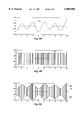
- FIGS. 6A, 6B, 6C, 7A, 7B and 7C are provided to illustrate waveforms at various stages of processing in the transmitter 68 and receiver 90 of the present invention. Specifically, FIGS. 6A-C show an analog waveform at various stages in the transmitter 68, while FIGS. 7A-C show the waveform in the receiver 90.
- FIG. 6A shows the information signal or stream 70 which is received at the input of the amplitude modulator 84 in FIG. 5.
- FIG. 6B shows a representative spreading sequence 72.
- the spreading sequence 72 is a predefined repetitious pattern usually in digital format, regardless of whether the information signal to be modulated is analog or digital. Although the waveform appears to go from +1 to -1, +1 should be considered a logic high, and -1 should be considered to be a logic low. It should be observed that the spreading sequence 72 would normally be repeated much more rapidly than shown here. However, the repetition rate was selected for the purpose of visual clarity.
- FIG. 6C shows the spread signal 74 which is the amplitude modulated combination of the analog waveform 70 of FIG. 6A and the spreading signal 72 of FIG. 6B. It should also be observed that because the signals 70,72 are amplitude modulated, the spread signal 74 has an upper sideband 104 and a lower sideband 106, where the lower sideband 104 is the inverted form of the upper sideband 106.
- FIG. 5 shows that the preferred embodiment uses amplitude modulation
- other types of modulation can be used, as long as the receiver 90 demodulates the spread-spectrum signal 80 using the appropriate method of demodulation.
- frequency modulation can also be used in the transmitter 68, and consequently the receiver 90 will demodulate a frequency modulated spread-spectrum signal 80.
- FIGS. 7A-C show the critical waveforms in the receiver 90.
- the matched filter 96 is a SAW filter in this embodiment.
- the impulse response is a time-reversed copy of one period of the spreading sequence 72.
- the output 88 of the matched filter 96 is shown in FIG. 7A.
- FIG. 7B shows the output 100 of the envelope detector 98.
- this circuit 98 is a simple diode detector which will track the peaks of the matched filter output 88.
- the information signal 70 is seen as riding on the peaks of the matched filter output 88, or on the peaks of the sawtooth output of the envelope detector 100.
- FIG. 7C shows the final output signal 70 which is the information signal, with the sawtooth waveform 100 filtered out.
- a DC blocking device is used to complete the demodulation process in the low-pass filter 102.
- the rate at which the spreading waveform 72 is generated may be varied in proportion to the information signal 70.
- This is analogous to the frequency modulation (FM) mentioned previously, with the exception that the spread sequence 74 is being modulated rather than a carrier 76.
- one advantage of using modulation is that radio frequency upconversion is no longer required to be tied directly to the information signal 70 modulation. Consequently, this allows use of, for example, FM upconversion and downconversion to place the spread signals 74 on the selected channel 82.
Abstract
Description
Claims (21)
Priority Applications (1)
| Application Number | Priority Date | Filing Date | Title |
|---|---|---|---|
| US08/689,194 US6005886A (en) | 1996-08-05 | 1996-08-05 | Synchronization-free spread-spectrum demodulator |
Applications Claiming Priority (1)
| Application Number | Priority Date | Filing Date | Title |
|---|---|---|---|
| US08/689,194 US6005886A (en) | 1996-08-05 | 1996-08-05 | Synchronization-free spread-spectrum demodulator |
Publications (1)
| Publication Number | Publication Date |
|---|---|
| US6005886A true US6005886A (en) | 1999-12-21 |
Family
ID=24767422
Family Applications (1)
| Application Number | Title | Priority Date | Filing Date |
|---|---|---|---|
| US08/689,194 Expired - Fee Related US6005886A (en) | 1996-08-05 | 1996-08-05 | Synchronization-free spread-spectrum demodulator |
Country Status (1)
| Country | Link |
|---|---|
| US (1) | US6005886A (en) |
Cited By (11)
| Publication number | Priority date | Publication date | Assignee | Title |
|---|---|---|---|---|
| US20020094012A1 (en) * | 2000-03-07 | 2002-07-18 | Wherenet Corporation | Geolocation system with controllable tags enabled by wireless communications to the tags |
| WO2002073840A1 (en) * | 2001-03-12 | 2002-09-19 | Conexant Systems, Inc. | Method and apparatus for spread spectrum radio signal recovery in wideband spread spectrum communication systems |
| US20020136277A1 (en) * | 2000-11-14 | 2002-09-26 | Reed Irving S. | Self-synchronizing adaptive multistage receiver for wireless communication systems |
| US20050047490A1 (en) * | 2003-08-28 | 2005-03-03 | Haitao Zhang | Method and apparatus for removing code aliases when using short synchronization codes |
| US20050047491A1 (en) * | 2003-08-28 | 2005-03-03 | Haitao Zhang | Method and apparatus for improving channel estimate based on short synchronization code |
| US20050123061A1 (en) * | 2003-12-03 | 2005-06-09 | Smith Stephen F. | Multidimensional signal modulation and/or demodulation for data communications |
| US20050141594A1 (en) * | 2003-12-31 | 2005-06-30 | Smith Stephen F. | Hybrid spread spectrum radio system |
| US7092440B1 (en) | 2000-09-27 | 2006-08-15 | Ut-Battelle Llc | Hybrid spread-spectrum technique for expanding channel capacity |
| US7315563B2 (en) | 2003-12-03 | 2008-01-01 | Ut-Battelle Llc | Multicarrier orthogonal spread-spectrum (MOSS) data communications |
| US8255276B1 (en) | 2000-03-09 | 2012-08-28 | Impulse Radio, Inc. | System and method for generating multimedia accompaniments to broadcast data |
| US9094186B2 (en) | 2000-03-09 | 2015-07-28 | Impulse Radio, Inc | System and method for transmitting digital multimedia data with analog broadcast data |
Citations (3)
| Publication number | Priority date | Publication date | Assignee | Title |
|---|---|---|---|---|
| US4449230A (en) * | 1981-04-07 | 1984-05-15 | Sony Corporation | Apparatus for demodulating an AM stereophonic signal |
| US5353301A (en) * | 1993-09-17 | 1994-10-04 | Motorola, Inc. | Method and apparatus for combining multipath spread-spectrum signals |
| US5442662A (en) * | 1993-07-05 | 1995-08-15 | Oki Electric Industry Co., Ltd. | Code-division multiple-access communication system providing enhanced capacity within limited bandwidth |
-
1996
- 1996-08-05 US US08/689,194 patent/US6005886A/en not_active Expired - Fee Related
Patent Citations (3)
| Publication number | Priority date | Publication date | Assignee | Title |
|---|---|---|---|---|
| US4449230A (en) * | 1981-04-07 | 1984-05-15 | Sony Corporation | Apparatus for demodulating an AM stereophonic signal |
| US5442662A (en) * | 1993-07-05 | 1995-08-15 | Oki Electric Industry Co., Ltd. | Code-division multiple-access communication system providing enhanced capacity within limited bandwidth |
| US5353301A (en) * | 1993-09-17 | 1994-10-04 | Motorola, Inc. | Method and apparatus for combining multipath spread-spectrum signals |
Cited By (25)
| Publication number | Priority date | Publication date | Assignee | Title |
|---|---|---|---|---|
| US20020094012A1 (en) * | 2000-03-07 | 2002-07-18 | Wherenet Corporation | Geolocation system with controllable tags enabled by wireless communications to the tags |
| US6859485B2 (en) * | 2000-03-07 | 2005-02-22 | Wherenet Corporation | Geolocation system with controllable tags enabled by wireless communications to the tags |
| US10819298B2 (en) | 2000-03-09 | 2020-10-27 | Dts, Inc. | System and method for generating multimedia accompaniments to broadcast data |
| US10735178B2 (en) | 2000-03-09 | 2020-08-04 | Dts, Inc. | System and method for transmitting digital multimedia data with analog broadcast data |
| US10044333B2 (en) | 2000-03-09 | 2018-08-07 | Dts, Inc. | System and method for generating multimedia accompaniments to broadcast data |
| US9337791B1 (en) | 2000-03-09 | 2016-05-10 | Impulse Radio Llc | System and method for generating multimedia accompaniments to broadcast data |
| US9094186B2 (en) | 2000-03-09 | 2015-07-28 | Impulse Radio, Inc | System and method for transmitting digital multimedia data with analog broadcast data |
| US8255277B1 (en) | 2000-03-09 | 2012-08-28 | Impulse Radio, Inc. | System and method for generating multimedia accompaniments to broadcast data |
| US8255276B1 (en) | 2000-03-09 | 2012-08-28 | Impulse Radio, Inc. | System and method for generating multimedia accompaniments to broadcast data |
| US7092440B1 (en) | 2000-09-27 | 2006-08-15 | Ut-Battelle Llc | Hybrid spread-spectrum technique for expanding channel capacity |
| US20020136277A1 (en) * | 2000-11-14 | 2002-09-26 | Reed Irving S. | Self-synchronizing adaptive multistage receiver for wireless communication systems |
| US7061970B2 (en) * | 2000-11-14 | 2006-06-13 | Irving Reed | Self-synchronizing adaptive multistage receiver for wireless communication systems |
| US7095804B2 (en) | 2001-03-12 | 2006-08-22 | Skyworks Solutions, Inc. | Method and apparatus for spread spectrum radio signal recovery in wideband spread spectrum communication systems |
| US20020131482A1 (en) * | 2001-03-12 | 2002-09-19 | Conexant Systems, Inc. | Method and apparatus for spread spectrum radio signal recovery in wideband spread spectrum communication systems |
| WO2002073840A1 (en) * | 2001-03-12 | 2002-09-19 | Conexant Systems, Inc. | Method and apparatus for spread spectrum radio signal recovery in wideband spread spectrum communication systems |
| US7869488B2 (en) | 2003-08-28 | 2011-01-11 | Qualcomm Incorporated | Method and apparatus for removing code aliases when using short synchronization codes |
| US20050047491A1 (en) * | 2003-08-28 | 2005-03-03 | Haitao Zhang | Method and apparatus for improving channel estimate based on short synchronization code |
| US20050047490A1 (en) * | 2003-08-28 | 2005-03-03 | Haitao Zhang | Method and apparatus for removing code aliases when using short synchronization codes |
| US7315563B2 (en) | 2003-12-03 | 2008-01-01 | Ut-Battelle Llc | Multicarrier orthogonal spread-spectrum (MOSS) data communications |
| US7340001B2 (en) | 2003-12-03 | 2008-03-04 | Ut-Battelle Llc | Multidimensional signal modulation and/or demodulation for data communications |
| US20050123061A1 (en) * | 2003-12-03 | 2005-06-09 | Smith Stephen F. | Multidimensional signal modulation and/or demodulation for data communications |
| US7656931B2 (en) | 2003-12-31 | 2010-02-02 | Ut-Battelle, Llc | Hybrid spread spectrum radio system |
| US7660338B2 (en) | 2003-12-31 | 2010-02-09 | Ut-Battelle, Llc | Hybrid spread spectrum radio system |
| WO2005067161A1 (en) * | 2003-12-31 | 2005-07-21 | Ut-Battelle, Llc | Hybrid spread spectrum radio system |
| US20050141594A1 (en) * | 2003-12-31 | 2005-06-30 | Smith Stephen F. | Hybrid spread spectrum radio system |
Similar Documents
| Publication | Publication Date | Title |
|---|---|---|
| US5432815A (en) | Data modulator-demodulator apparatus of a spread spectrum communication system | |
| US5420896A (en) | Synchronous spread-spectrum communications system and method | |
| US5712869A (en) | Data transmitter and receiver of a spread spectrum communication system using a pilot channel | |
| US6411646B1 (en) | Direct conversion time division duplex radio, direct sequence spread spectrum cordless telephone | |
| US5179572A (en) | Spread spectrum conference calling system and method | |
| US6005886A (en) | Synchronization-free spread-spectrum demodulator | |
| KR19990067042A (en) | Method and apparatus for suppressing interference in spread spectrum signals | |
| CA2040060A1 (en) | Radio communication system using spread spectrum techniques | |
| JPH0799487A (en) | Spread spectrum communication equipment and radio communication equipment | |
| JP2809097B2 (en) | Radio station equipment | |
| US4953178A (en) | Spread spectrum communication system | |
| US5469470A (en) | Spread spectrum communication system using two-predetermined-code pseudo-noise signals | |
| WO1992015163A1 (en) | Method and apparatus for real-time demodulation of a gmsk signal by a non-coherent receiver | |
| EP0111937B1 (en) | Privacy signal transmission system | |
| US5852636A (en) | Method of and apparatus for modulation of FSK carrier in a very narrow band | |
| US4573205A (en) | Technique for secure communications on FM radio channels | |
| WO1993009625A1 (en) | Optimized clock recovery for an msk system | |
| US6879647B1 (en) | Radio receiver AM-MSK processing techniques | |
| US6198764B1 (en) | Method for the transfer of a digital data signal from a transmitter to a receiver | |
| EP0301240A2 (en) | Direct sequence digital spread spectrum modem | |
| US6961431B2 (en) | Analog privacy scrambler and scrambling method | |
| US20060291539A1 (en) | Transmit signal combining to allow passive recovery in a spread spectrum receiver | |
| EP1204214A1 (en) | Direct sequence spread spectrum modulation of an analog signal | |
| KR100337803B1 (en) | Secret communication system in the data and voice | |
| CA2615665C (en) | Synchronous spread-spectrum communications system and method |
Legal Events
| Date | Code | Title | Description |
|---|---|---|---|
| AS | Assignment |
Owner name: DIGITAL RADIO COMMUNICATIONS CORPORATION, UTAH Free format text: ASSIGNMENT OF ASSIGNORS INTEREST;ASSIGNOR:SHORT, ROBERT;REEL/FRAME:008205/0104 Effective date: 19960917 |
|
| AS | Assignment |
Owner name: DIGITAL RADIO COMMUNICATIONS CORP., UTAH Free format text: ASSIGNMENT OF ASSIGNORS INTEREST;ASSIGNOR:DIGITAL RADIO COMMUNICATIONS CORP.;REEL/FRAME:008815/0481 Effective date: 19971112 Owner name: DIGITAL SCIENTIFIC, INC., UTAH Free format text: ASSIGNMENT OF ASSIGNORS INTEREST;ASSIGNOR:DIGITAL RADIO COMMUNICATIONS CORP.;REEL/FRAME:008815/0481 Effective date: 19971112 |
|
| AS | Assignment |
Owner name: MCCLOSKEY, THOMAS D., JR TRUSTEE OF THE MCCLOSKEY Free format text: ASSIGNMENT OF ASSIGNORS INTEREST;ASSIGNOR:WORLD WIRELESS COMMUNICATIONS, INC.;REEL/FRAME:009367/0613 Effective date: 19980515 |
|
| AS | Assignment |
Owner name: WORLD WIRELESS COMMUNICATIONS, INC., UTAH Free format text: ASSIGNMENT OF ASSIGNORS INTEREST;ASSIGNOR:DIGITAL RADIO COMMUNICATIONS CORPORATION;REEL/FRAME:010135/0435 Effective date: 19971231 |
|
| AS | Assignment |
Owner name: FRYING PAN PARTNERS, LLC, COLORADO Free format text: SECURITY INTEREST;ASSIGNOR:WORLD WIRELESS COMMUNICATIONS, INC.;REEL/FRAME:010272/0804 Effective date: 19990514 Owner name: STERLING TECHNOLOGY PARTNERS, LLC, CALIFORNIA Free format text: SECURITY INTEREST;ASSIGNOR:WORLD WIRELESS COMMUNICATIONS, INC.;REEL/FRAME:010272/0804 Effective date: 19990514 Owner name: KELLY, JAMES T., PENNSYLVANIA Free format text: SECURITY INTEREST;ASSIGNOR:WORLD WIRELESS COMMUNICATIONS, INC.;REEL/FRAME:010272/0804 Effective date: 19990514 Owner name: K.R. BRAITHWAITE, CALIFORNIA Free format text: SECURITY INTEREST;ASSIGNOR:WORLD WIRELESS COMMUNICATIONS, INC.;REEL/FRAME:010272/0804 Effective date: 19990514 Owner name: ORBITER FUND LTD., NEW YORK Free format text: SECURITY INTEREST;ASSIGNOR:WORLD WIRELESS COMMUNICATIONS, INC.;REEL/FRAME:010272/0804 Effective date: 19990514 Owner name: THOMAS D. MCCLOSKEY, JR., TRUSTEE, COLORADO Free format text: SECURITY INTEREST;ASSIGNOR:WORLD WIRELESS COMMUNICATIONS, INC.;REEL/FRAME:010272/0804 Effective date: 19990514 Owner name: LANCER OFFSHORE, INC., NEW YORK Free format text: SECURITY INTEREST;ASSIGNOR:WORLD WIRELESS COMMUNICATIONS, INC.;REEL/FRAME:010272/0804 Effective date: 19990514 Owner name: DPM INVESTMENT CORP., COLORADO Free format text: SECURITY INTEREST;ASSIGNOR:WORLD WIRELESS COMMUNICATIONS, INC.;REEL/FRAME:010272/0804 Effective date: 19990514 Owner name: CJL INVESTMENTS, LLC, CALIFORNIA Free format text: SECURITY INTEREST;ASSIGNOR:WORLD WIRELESS COMMUNICATIONS, INC.;REEL/FRAME:010272/0804 Effective date: 19990514 |
|
| AS | Assignment |
Owner name: WORLD WIRELESS COMMUNICATIONS, INC., COLORADO Free format text: TERMINATION OF SECURITY INTEREST.;ASSIGNORS:STERLING TECHNOLOGIES PARTNERS LLC;MCCLOSKEY TRUST, THE;DPM INVESTMENT CORP.;AND OTHERS;REEL/FRAME:011944/0736 Effective date: 20000515 |
|
| AS | Assignment |
Owner name: LANCER OFFSHORE, INC., NETHERLANDS ANTILLES Free format text: ASSIGNMENT OF ASSIGNORS INTEREST;ASSIGNOR:WORLD WIRELESS COMMUNICATIONS, INC.;REEL/FRAME:012090/0301 Effective date: 20010517 |
|
| AS | Assignment |
Owner name: LANCER PARTNERS L.P., CONNECTICUT Free format text: SECURITY INTEREST;ASSIGNOR:WORLD WIRELESS COMMUNICATIONS, INC.;REEL/FRAME:012119/0089 Effective date: 20010807 |
|
| REMI | Maintenance fee reminder mailed | ||
| LAPS | Lapse for failure to pay maintenance fees | ||
| STCH | Information on status: patent discontinuation |
Free format text: PATENT EXPIRED DUE TO NONPAYMENT OF MAINTENANCE FEES UNDER 37 CFR 1.362 |
|
| FP | Lapsed due to failure to pay maintenance fee |
Effective date: 20031221 |