US6011814A - Adaptive comb filter and decision feedback equalizer for noise suppression - Google Patents
Adaptive comb filter and decision feedback equalizer for noise suppression Download PDFInfo
- Publication number
- US6011814A US6011814A US08/992,498 US99249897A US6011814A US 6011814 A US6011814 A US 6011814A US 99249897 A US99249897 A US 99249897A US 6011814 A US6011814 A US 6011814A
- Authority
- US
- United States
- Prior art keywords
- comb filter
- dfe
- adaptive comb
- adaptive
- signal
- Prior art date
- Legal status (The legal status is an assumption and is not a legal conclusion. Google has not performed a legal analysis and makes no representation as to the accuracy of the status listed.)
- Expired - Lifetime
Links
Images


Classifications
-
- H—ELECTRICITY
- H04—ELECTRIC COMMUNICATION TECHNIQUE
- H04L—TRANSMISSION OF DIGITAL INFORMATION, e.g. TELEGRAPHIC COMMUNICATION
- H04L25/00—Baseband systems
- H04L25/02—Details ; arrangements for supplying electrical power along data transmission lines
- H04L25/03—Shaping networks in transmitter or receiver, e.g. adaptive shaping networks
- H04L25/03006—Arrangements for removing intersymbol interference
- H04L25/03012—Arrangements for removing intersymbol interference operating in the time domain
- H04L25/03019—Arrangements for removing intersymbol interference operating in the time domain adaptive, i.e. capable of adjustment during data reception
- H04L25/03057—Arrangements for removing intersymbol interference operating in the time domain adaptive, i.e. capable of adjustment during data reception with a recursive structure
-
- H—ELECTRICITY
- H04—ELECTRIC COMMUNICATION TECHNIQUE
- H04L—TRANSMISSION OF DIGITAL INFORMATION, e.g. TELEGRAPHIC COMMUNICATION
- H04L25/00—Baseband systems
- H04L25/02—Details ; arrangements for supplying electrical power along data transmission lines
- H04L25/03—Shaping networks in transmitter or receiver, e.g. adaptive shaping networks
- H04L25/03006—Arrangements for removing intersymbol interference
- H04L2025/0335—Arrangements for removing intersymbol interference characterised by the type of transmission
- H04L2025/03375—Passband transmission
- H04L2025/03414—Multicarrier
-
- H—ELECTRICITY
- H04—ELECTRIC COMMUNICATION TECHNIQUE
- H04L—TRANSMISSION OF DIGITAL INFORMATION, e.g. TELEGRAPHIC COMMUNICATION
- H04L25/00—Baseband systems
- H04L25/02—Details ; arrangements for supplying electrical power along data transmission lines
- H04L25/03—Shaping networks in transmitter or receiver, e.g. adaptive shaping networks
- H04L25/03006—Arrangements for removing intersymbol interference
- H04L2025/03433—Arrangements for removing intersymbol interference characterised by equaliser structure
- H04L2025/03439—Fixed structures
- H04L2025/03445—Time domain
- H04L2025/03471—Tapped delay lines
- H04L2025/03484—Tapped delay lines time-recursive
- H04L2025/0349—Tapped delay lines time-recursive as a feedback filter
Definitions
- the present invention relates generally to data communications, and more particularly, to an apparatus and method for suppressing low frequency periodic impulse noise generated near a receiver in a multipoint communications environment.
- DSL Digital Subscriber Line
- Devices communicate by modulating a baseband signal carrying digital data, converting the modulated digital data signal to an analog signal, and transmitting the analog signal over a conventional copper wire pair using techniques that are known in the art. These known techniques include mapping the information to be transmitted into a signal space constellation, differentially encoding the information to reduce errors and improve throughput, and transmitting the information over a communication channel.
- the constellation can include both analog and digital information or often merely digital information.
- the signal is received, equalized and decoded in accordance with techniques that those skilled in the art will appreciate.
- a control device i.e., one that is located at a telephone company central office, connects on the communication channel to a plurality of remote devices typically located at a customer residential or business location.
- This topography is known as a multipoint communication environment because one control device is communicating with a plurality of remote devices co-located at a remote location, over a single communication channel.
- the communication technique between the control device and the remote device is generally half duplex in nature, meaning that only one device may transmit at any particular time.
- a preamble which allows the devices to synchronize at the start of each message is required.
- carrierless amplitude/phase (CAP) modulation uses a precoder while discrete multi-tone (DMT) selectively disables the affected frequency bins.
- DMT discrete multi-tone
- the 60 Hz periodic impluse noise (such as that generated by a local electrical appliance such as a light dimmer) is allowed to exist and the resulting errors are corrected by a Reed Solomon (RS) code, which can delay the data.
- RS Reed Solomon
- the RS and DMT codes are ineffective.
- the precoder used with CAP is located in the transmitter, and will cause discontinuities when the transmitter is switched on and off, as frequently occurs in a multipoint environment.
- control device in the multipoint environment can have but one set of precoder coefficients for broadcasting to all remote devices, which may have different precoder needs. Also, ringing caused by on/off polling cannot be canceled by a precoder because the transmitter and precoder are inoperable during the ringing transient.
- the present invention provides an improvement to a half duplex multipoint communication environment by enabling a device receiver to efficiently suppress low frequency periodic impulse noise generated by local sources.
- This low frequency noise can be for example, the 60 Hz noise generated by a light dimmer or other electrical appliance located near the device receiver, or the noise can be crosstalk generated in the vicinity of the device receiver.
- the device receiver can suppress or eliminate this local low frequency noise, thus improving the performance of the receiver of the communication device.
- the present invention provides an apparatus for noise suppression, the apparatus comprising a comb filter and a decision feedback equalizer (DFE).
- the DFE is configured to operate on those low frequency impulse signals having a period that is proportionally related to the number of tap coefficients of the DFE.
- the number of tap coefficients in the DFE is related to the frequency of noise that can be suppressed in that the more the taps, the longer the period (i.e., the lower the frequency) of noise that can be canceled.
- an adaptive comb filter which, if certain conditions are satisfied, further enhance the noise suppression of the DFE using merely one (1) adaptive coefficient.
- a single coefficient is sufficient so long as the period of the noise sought to be suppressed is exactly an integer number of symbol periods.
- a ring buffer located within the adaptive comb filter stores one period of the low frequency noise, enabling a single adaptive coefficient to suppress the noise.
- the adaptive comb filter also includes a gating apparatus configured to enable the comb filter output only when the energy in the adaptive comb filter exceeds a predefined threshold.
- the present invention also includes a method for suppressing periodic impulse noise in the receiver of a digital subscriber line (DSL) communication device.
- First a signal is received by a receiver located in a DSL communication device.
- the signal is operated on by an equalizer as is known in the art, and optionally by a nonlinear decoder as is known in the art.
- the output of the equalizer, or nonlinear decoder if used has the output of a decision feedback equalizer (DFE) added thereto.
- DFE decision feedback equalizer
- the DFE can suppress or eliminate low frequency periodic impulse noise having a period that is proportionally related to the number of tap coefficients of the DFE. If certain conditions are satisfied, the output of an adaptive comb filter is added to the combined output of the equalizer and DFE.
- the method also includes the step of storing in a ring buffer or bulk memory device, which is located within the adaptive comb filter, at least one of the periods of the noise signal. This enables an adaptive comb filter having a single coefficient the ability to efficiently suppress this low frequency noise. Furthermore, the method of the adaptive comb filter and DFE includes the step of gating the adaptive comb filter in order to enable the output of the adaptive comb filter only when the energy in the adaptive comb filter exceeds a predetermined threshold.
- the present invention includes an apparatus and method wherein the adaptive comb filter is provided with additional coefficients, thus enabling the filter to track a frequency error between the noise and the symbol rate of the communication device.
- the invention has numerous advantages, a few of which are delineated hereafter, as merely examples.
- An advantage of the adaptive comb filter and decision feedback equalizer is that it substantially reduces or eliminates any low frequency periodic impulse noise generated in the vicinity of a DSL receiver.
- Another advantage of the adaptive comb filter and decision feedback equalizer is that it utilizes an adaptive comb filter having few or a single coefficient, thus reducing the amount of system resource required to perform the adaptive calculations.
- Another advantage of the adaptive comb filter and decision feedback equalizer is the use of a gated comb filter which activates only when impulses are present so as to reduce noise enhancement.
- Another advantage of the adaptive comb filter and decision feedback equalizer is that it recovers gracefully from lengthy interruptions in the signal path and thus, can be used in a multipoint communication environment where the received signal is periodically interrupted.
- Another advantage of the adaptive comb filter and decision feedback equalizer is that it can be used to track frequency offset by adjusting the comb size.
- Another advantage of the adaptive comb filter and decision feedback equalizer is that it allows a control device to have multiple sets of adaptive decision feedback equalizer coefficients thus enabling a single control device to maintain equalization with a plurality of remote devices.
- Another advantage of the adaptive comb filter and decision feedback equalizer is it's ability to squelch the ringing that occurs on the communication channel when other transmitters in the multipoint environment pulse on and off.
- Another advantage of the adaptive comb filter and decision feedback equalizer is that it is simple in design, reliable in operation, and its design lends itself to economical mass production in communication devices.
- FIG. 1 is a schematic view illustrating a multipoint communications environment
- FIG. 2 is a block diagram of a communications device including the adaptive comb filter and decision feedback equalizer low frequency noise suppression logic of the present invention
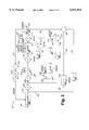
- FIG. 3 is a block diagram illustrating the adaptive comb filter and decision feedback equalizer of the present invention.
- FIG. 4 is a block diagram illustrating the adaptive comb filter and decision feedback equalizer of the present invention used in a control device of FIG. 1 in a multipoint environment;
- FIG. 5 is a flow chart illustrating the operation of the adaptive comb filter and decision feedback equalizer.
- the present invention can be implemented in software, hardware, or a combination thereof.
- the elements of the present invention are implemented in software that is stored in a memory and that configures and drives a suitable digital signal processor (DSP) situated in a communication device.
- DSP digital signal processor
- the foregoing software can be stored on any computer-readable medium for transport or for use by or in connection with any suitable computer-related system or method.
- a computer-readable medium is an electronic, magnetic, optical, or other physical device or means that can contain or store a computer program for use by or in connection with a computer-related system or method.
- the present invention is applicable to all modulation schemes as known in the art.
- FIG. 1 shows a schematic view illustrating a multipoint communications environment 11 in which devices employing the noise suppression apparatus and method of the present invention are used.
- Remote location 16 is connected to central office location 12 via communication channel 14.
- control device 13 and remote device 18 are illustratively digital subscriber line (DSL) communication devices.
- DSL digital subscriber line
- the concepts of the present invention are applicable to various other types of communication devices employing adaptive equalization.
- Communication channel 14 is typically the copper wire pair that extends between a telephone company central office and a remote residential, business, or any other location served by local telephone service.
- Remote location 16 may contain a plurality of remote devices 18 connecting a plurality of user devices 17 to communication channel 14 via communication bus 19.
- Communication bus 19 is illustratively the copper wiring infrastructure used throughout a remote location to connect remote devices 18 to communication channel 14.
- Remote devices 18 are typically located in a residential or business location. These locations often contain low frequency noise generating electrical appliances, such as light dimmers and other electrical devices. These appliances typically generate low frequency periodic impulse noise in the frequency range of 60-120 Hz. Furthermore, other signal generating sources may be located in the vicinity of remote device 18, these sources generate crosstalk, which can further degrade the performance of the receiver of remote device 18.
- control device 13 and remote devices 18 employing the concepts and features of the present invention, it is possible for the receiver located in remote device 18 and control device 13 to efficiently suppress or cancel this low frequency periodic impulse noise and crosstalk generated in it's vicinity.
- the present invention will be described as residing in the receiver of remote device 18, however, the noise suppression apparatus and method can be applied to any communication receiver, including the receiver located in control device 13.
- FIG. 2 shown is a schematic view illustrating remote device 18 of FIG. 1 including the adaptive comb filter and decision feedback equalizer noise suppression logic of the present invention.
- control device 13 will transmit signals to remote devices 18 over communications channel 14.
- remote devices 18 will transmit signals to control device 13.
- Remote devices 18 contain noise suppression logic 200 which enable the remote devices to efficiently suppress or eliminate low frequency periodic impulse noise. Still referring to FIG. 2, remote device 18 contains conventional components as is known in the art of data communications.
- Digital Signal Processor (DSP) 21 controls the operation of the devices' transmitter 22 and receiver 23 through logical interface 24, and couples to line interface 26 to gain access to communications channel 14.
- comb filter and DFE logic 200 which enables remote device 18 to reliably and economically suppress or eliminate low frequency periodic impulse noise generated in the vicinity of receiver 23.
- memory 27, which also includes comb filter and DFE logic 200 is also included within remote device 18. In a preferred embodiment, the logic of the present invention is executed within DSP 21 and is therefore shown as residing in both receiver 23 and memory 27.
- FIG. 3 illustrated is a block diagram showing the adaptive comb filter, decision feedback equalizer (DFE), and related circuitry of the present invention as applied to remote device 18 as illustrated in FIG. 2.
- DFE decision feedback equalizer
- Decision feedback equalizer (DFE) 231 adds a compensation signal on line 234 to adder 206.
- Adder 206 adds the compensation signal from DFE 231 with the output of conventional equalizer 202 on line 204.
- the output of adder 206 (the combined output of DFE 231 and equalizer 202) is supplied to memory device 251 on line 245.
- a nonlinear encoder can be placed at the output of equalizer 202 (i.e., on line 204) as is known in the art.
- Adder 248 receives the output of adaptive comb filter 232 on line 246 and adds it to the combined equalizer and DFE output on line 249 if certain conditions are satisfied.
- adaptive comb filter provides gating function 252. Gating is accomplished by computing the total energy in filter 232, and if that energy exceeds some threshold (indicating that low frequency impulse noise is present), then the output of adaptive comb filter 232 is computed and added to the output of the combined equalizer 202 and DFE 231. If the energy is below the threshold then the output of adaptive comb filter 232 is set to zero by gating function 252 on line 253 through logical switch 254. This significantly reduces noise enhancement that may otherwise be caused by adaptive comb filter 232.
- a threshold value of two to four times the mean squared error on line 219 at the input to Beta multiplier 221 has been found appropriate.
- the input to adaptive comb 232 is computed using the combined output of equalizer 202 and DFE 231 on line 245. This will prevent adaptive comb filter 232 from regenerating impulses that may have been removed by DFE 231. DFE 231 also serves to whiten the impulses that may have been distorted by equalizer 202. Equalizer 202 is inverting the channel between the remote transmitter and the local receiver. The noise impulses have been detected near the local receiver and did not pass through the entire channel. Thus, equalizer 202 will shape the impulses and may reduce the effectiveness of adaptive comb filter 232. Using the combined output of DFE 231 and equalizer 202 as input to adaptive comb filter 232 improves the effectiveness of comb filter 232.
- the combined output of DFE 231 and equalizer 202 is supplied to memory delay element 251 on line 245 and the output of memory delay element 251 is supplied on line 256 to adder 257.
- the output of slicer 209 on line 225 is subtracted from the output of memory delay element 251 by adder 257, and supplied to carrier off switch 259 on line 258.
- carrier off switch 259 When carrier off switch 259 is positioned for normal operation, output of adder 257 on line 258 is supplied to bulk memory device 263.
- Bulk memory device, or ring buffer, 263 delays approximately one period of the periodic impulses.
- the output of bulk memory device 263 supplies the input to adaptive comb filter 232, which will shape the regenerated impulse and track frequency offset variations.
- Adaptive comb filter 232 can be a complex finite impulse response (FIR) filter.
- FIR finite impulse response
- N is the number of symbol delays in bulk memory device 263 (i.e., a ring buffer) and approximates the one period of the periodic impulse sought to be canceled.
- carrier off switches are as follows. When the transmit carrier is off, these switches, 259 and 224 provide a zero ideal reference signal output from slicer 209, and select the output of adaptive comb filter 232 to feed back as the input to adaptive comb filter 232. Detection of carrier state is well known in the art.
- the fully compensated signal on line 207 is scaled down by 1/scale factor 208. This scaling is done to enable the signal to fit a uniform grid suitable for slicing.
- the grid is typically based upon a power of two (2), such that a simple mask operation slices the original signal, as will be appreciated by one skilled in the art.
- Slicer 209 may optionally include a trellis decoder and Viterbi decoder as known in the art.
- the output of slicer 209 on line 212 includes an index for subsequent data encoding and an ideal reference signal representing the ideal vector that would have been received in the absence of any signal distortion.
- the ideal reference signal is then scaled up in scaler 214 to restore it to the same size as the original output of equalizer 202.
- Scaler 214 provides an operation that is a function of the data rate such that the gain of equalizer 202 will be constant for all data rates. This allows the data rate to be seamlessly changed on a frame by frame basis without disrupting the operation of adaptive comb filter 232 and DFE 231.
- Switch 224 located in the ideal reference signal path line 216 is positioned to provide the zero vector prior to receiving the Start of Message (SOM) special marker signal.
- Special marker detector 261 detects this SOM signal and acts to position switch 224 in order to pass the SOM signal and the subsequent ideal reference signals on line 225.
- special marker detector 261 positions switch 224 on the following frame to again generate the zero vector.
- the resulting ideal reference signals are valid when no signal is received. Without a valid reference signal, DFE 231 of length M would be unable to correct the first M symbols of every received message. M refers to the number of coefficients in DFE 231.
- the ideal reference signal on line 225 is subtracted from the previous output of equalizer 202 on line 227 by subtractor 226, after being delayed one period by delay element 244, in order to generate an updated error signal on line 229 for input to DFE 231.
- the previous symbol is used because the reference signal corresponds to the previous symbol.
- the input signal on line 229 is the error between the output of equalizer 202 and the ideal reference generated by slicer 209. Only the equalizer error signal is stored in the memory of DFE 231 and adaptive comb filter 232, thus a change in the adaptive coefficients of DFE 231 and adaptive comb filter 232 will not affect the received data signal, but merely the noise signal. This provides the advantage of data rate transparency and continuity during the intermittent multipoint signal.
- the adaptive comb filter and decision feedback equalizer are also designed to eliminate any residual error present in the system.
- the fully compensated signal on line 207 is subtracted from the ideal reference signal on line 217 in subtractor 218.
- This error signal on line 219 is scaled by beta scaler operator 221, thus producing the residual error signal on line 222 used to update the coefficients of equalizer 202 and the DFE 231 and adaptive comb filter 232 as indicated by the update arrow.
- the update arrows into DFE 231 and adaptive comb filter 232 may have larger beta scalers than that used for equalizer 202. A beta increase of 2 4 has been found useful.
- a flywheel circuit comprised of elements 242, 241 and switch 259.
- the receiver is interrupted by periodic transmissions causing discontinuities in the memories of such devices as equalizers and filters.
- the transmitter of the instant device may be active, or the transmitter of other remote devices connected to communication channel 14 may be active.
- the signal on line 258 used as the input to adaptive comb filter 232 is invalid.
- the transmitter may saturate the input making any attempt at signal recovery unlikely to succeed.
- the flywheel circuit allows the previous sample stored in the memory of adaptive comb filter 232 to be reused.
- the sample is passed through one sample delay element 242 such that the delay around the flywheel circuit is exactly one period of the interfering signal.
- Alpha attenuator 241 is optionally provided to incrementally attenuate the signal.
- Alpha attenuator 241 assures that a signal will not remain stored in the memory of adaptive comb filter 232 indefinitely. Once the signal in filter 232 has attenuated, the next arrival of an interfering signal will remain uncompensated, however subsequent signals will be fully compensated. For example, an alpha attenuator value of 0.9 will reduce regenerated impulses by 10% each period of the impulse eventually eliminating the regenerated response.
- FIG. 4 shown is a block diagram illustrating the adaptive comb filter and decision feedback equalizer used in a control device 13 in a multipoint environment.
- the like numbered elements of FIG. 4 perform the same functions as those in FIG. 3.
- FIG. 4 illustrates a control device 13 capable of storing and applying adaptive coefficients for a plurality of remote devices 18.
- conventional equalizer 202 is depicted in FIG. 4 as a plurality of equalizers 202a through 202n to correspond to a K plurality of remote devices 18, each having an equalizer with a different set of coefficients.
- DFE 231 is depicted as a plurality of DFE's 231a through 231n to correspond to a K plurality of remote devices 18, each having a DFE with a different set of coefficients.
- These, and other adaptive coefficients are stored in a common data memory (not shown) and can be recalled each time a remote device 18 transmits.
- Switches 256a through 256n and 251a through 251n select the proper equalizer and DFE (and respective coefficients) for the particular remote device 18 transmitting at the time. This arrangement provides true multipoint adaptive DFE operation insuring optimum performance from each remote device 18.
- Adaptive comb filter 232 is rejecting an independent, undesirable impulse signal that remains unchanged independent of the remote device 18.
- the impulse was generated locally near the receiver and is independent of the desired signal transmitted over communication channel 14. It is likely that common coefficients will be sufficient for all K remote devices 18.
- the propagation of the undesirable signal through equalizer 202 may be a function of the remote device 18 due to the independent equalizer coefficients.
- independent comb ring buffers i.e., bulk memory devices 263 of FIG. 3 may be desirable.
- the system depicted in FIG. 4 having two or more local comb coefficients could be used to adjust a common ring buffer to independent sets of equalizer coefficients.
- the forward, or conventional equalizer output is computed in block 301.
- DFE 231 is trained and then adaptive comb filter 232 is trained during the last 1/60 th second of equalizer training. This assures that one period of the undesirable signal (for example, a 60 Hz signal) will pass through DFE 231 and adaptive comb filter 232 during training. A peak error detector operates during this period and will detect the low frequency periodic impulse noise.
- Block 302 subtracts the previous ideal reference signal from the previous equalizer output in order to generate a new input to the adaptive comb filter and DFE.
- Block 303 computes the output of the DFE.
- Block 304 adds the equalizer output to the compensation signal output of the DFE in order to generate the DFE compensated signal.
- the total energy in the comb filter is computed.
- Block 307 decides whether the computed value from block 306 exceeds a threshold value. If the threshold value is not exceeded, the comb filter output is set to zero in block 308. If the value computed in block 306 exceeds the threshold value, the output of the comb filter is computed in block 309.
- Block 311 adds the output of the comb filter to the combined equalizer and DFE output. In block 312 this fully compensated signal is scaled, sliced and rescaled in order to generate the new ideal reference signal.
- Block 314 performs a data decoding operation by using the slicer output to decode the received data.
- Block 316 subtracts the compensated signal from the ideal reference signal in order to generate an updated error signal.
- the updated error signal is multiplied by Beta in order to scale it for use in updating the coefficients of the adaptive equalizer.
- the error signal is correlated with data stored in the equalizer, adaptive comb filter, and DFE in order to update their coefficients using the Least Mean Squares (LMS) algorithm.
- LMS Least Mean Squares
- DFE 231 memory can be derived from a Viterbi decoder used in systems that employ trellis coding.
- Trellis is a well known error detection and correction technique that employs the well known Viterbi algorithm and decoder. With each stage of delay in the Viterbi decoder, the signal estimate improves.
- DFE's are generally not used with trellis coding because a good signal estimate is typically unavailable for 16 or more symbol periods due to the Viterbi delay.
- the adaptive comb filter of the present invention can employ the delay of the Viterbi decoder to reduce the large delay of the ring buffer 263 of the adaptive comb filter.
- the ideal references derived from the Viterbi decoder can be used in the adaptive comb filter's ring buffer.
- the output of the DFE is computed as the accumulated products
- xd,yd are the DFE outputs at symbol instant i,cx,cy are the DFE's adaptive coefficients and xe,ye are the DFE inputs at symbol instant i-j.
- the complex (2-dimension) DFE provides spectral resolution across the full symbol bandwidth of the channel.
- a real (1-dimension) DFE is not desirable because it forces symmetrical solutions at half the symbol rate.
- the coefficients are updated by the following equations
- the output of the Comb filter is computed as the accumulated products
- the gating function is computed from the energy accumulation of products
- the adaptive comb coefficients are computed from the LMS algorithm
- the dominant comb coefficient as the center coefficient, for example coefficient 3 of 5. If the undesired signal is off frequency then the z -N delay will not be exactly correct. In this case the signal will eventually show up at z -N-1 or z 1-N With 5 or more adaptive coefficients the central coefficient will decay and one of the adjacent coefficients will grow. This can be detected and the coefficients can be shifted one symbol position to maintain the dominant coefficient at the center. When the coefficients are shifted the ring buffer pointer that picks up the z -N symbol can be incremented or decremented by one, effectively tracking the frequency error.
- the switch 259 selecting the comb filter input may be gated with higher precision. Even when a zero signal is expected, the output of the equalizer is valid and will contain impulses. The switch can continue to use its normal input after EOT until the local transmitter turns on, at which time it must select feedback from its own output. Then, after transmitting and selecting a new equalizer, then the normal equalizer and DFE outputs can be enabled into the comb filter to assist in detecting the SOM marker.
Abstract
Description
xd[i]+=cx[j]*xe[i-j]-cy[j]* ye[i-j]
yd[i]+=cx[j]*ye[i-j]+cy[j]* xe[i-j]
cx[j]+=ex*xe[i-j]
cy[j]+=-ex*xe[i-j]
xc[i]+=cx[j]*xe[i-j-N]-cy[j]*ye[i-j-N]
yc[j]+=cx[j]*ye[i-j-N]+cy[j]*xe[i-j-N]
Energy +=xe[i-j-N]*xe[i-j-N]+ye[i-j-N]*ye[i-j-N]
cx[j]+=ex*xe[i-j-N]
cy[j]+=-ey*xe[i-j-N]
Claims (50)
Priority Applications (1)
| Application Number | Priority Date | Filing Date | Title |
|---|---|---|---|
| US08/992,498 US6011814A (en) | 1997-09-30 | 1997-12-17 | Adaptive comb filter and decision feedback equalizer for noise suppression |
Applications Claiming Priority (2)
| Application Number | Priority Date | Filing Date | Title |
|---|---|---|---|
| US6047897P | 1997-09-30 | 1997-09-30 | |
| US08/992,498 US6011814A (en) | 1997-09-30 | 1997-12-17 | Adaptive comb filter and decision feedback equalizer for noise suppression |
Publications (1)
| Publication Number | Publication Date |
|---|---|
| US6011814A true US6011814A (en) | 2000-01-04 |
Family
ID=26739975
Family Applications (1)
| Application Number | Title | Priority Date | Filing Date |
|---|---|---|---|
| US08/992,498 Expired - Lifetime US6011814A (en) | 1997-09-30 | 1997-12-17 | Adaptive comb filter and decision feedback equalizer for noise suppression |
Country Status (1)
| Country | Link |
|---|---|
| US (1) | US6011814A (en) |
Cited By (25)
| Publication number | Priority date | Publication date | Assignee | Title |
|---|---|---|---|---|
| US6157680A (en) * | 1997-03-05 | 2000-12-05 | Paradyne Corporation | Audio distortion canceler method and apparatus |
| US6292816B1 (en) * | 1998-01-07 | 2001-09-18 | Samsung Electronics Co., Ltd. | Nonlinear equalizing apparatus |
| US6330275B1 (en) | 1997-06-23 | 2001-12-11 | Paradyne Corporation | Method and apparatus for overcoming periodic disturbances in digital subscriber loops |
| US6498808B1 (en) * | 1999-03-12 | 2002-12-24 | Aware, Inc. | Seamless rate adaptive multicarrier modulation system and protocols |
| US20030048840A1 (en) * | 2001-08-15 | 2003-03-13 | Ling Stanley K. | Adaptive equalizer |
| WO2003036892A1 (en) * | 2001-09-28 | 2003-05-01 | Siemens Aktiengesellschaft | Device and method for suppressing periodic interference signals |
| WO2003105339A1 (en) * | 2002-06-07 | 2003-12-18 | Tokyo Electron Limited | Multiline transmission in communication systems |
| US20040044942A1 (en) * | 1999-03-12 | 2004-03-04 | Aware, Inc. | Method for seamlessly changing power modes in an ADSL system |
| US6775320B1 (en) | 1999-03-12 | 2004-08-10 | Aware, Inc. | Method and a multi-carrier transceiver supporting dynamic switching between active application sets |
| US20040207399A1 (en) * | 2003-04-16 | 2004-10-21 | Manish Sharma | Magnetic filter |
| US6823002B1 (en) | 1999-12-15 | 2004-11-23 | Paradyne Corporation | Linear block interleaver for discrete multi-tone modulation |
| US20050053128A1 (en) * | 2003-07-08 | 2005-03-10 | Shearer Daniel D. | Adaptive frequency equalizer |
| US6965657B1 (en) | 1999-12-01 | 2005-11-15 | Velocity Communication, Inc. | Method and apparatus for interference cancellation in shared communication mediums |
| US6999504B1 (en) | 2000-11-21 | 2006-02-14 | Globespanvirata, Inc. | System and method for canceling crosstalk |
| US7038732B1 (en) * | 1998-05-12 | 2006-05-02 | Samsung Electronics Company, Ltd. | DTV signal with GCR components in plural-data-segment frame headers and receiver apparatus for such signal |
| US20060188035A1 (en) * | 1999-03-12 | 2006-08-24 | Aware, Inc. | Method for seamlessly changing power modes in an ADSL system |
| EP1361719A3 (en) * | 2002-05-09 | 2006-11-22 | Sony United Kingdom Limited | Multicarrier receiver with detection of burst noise |
| US20060291597A1 (en) * | 2005-06-01 | 2006-12-28 | Masahiro Take | Digital-signal-processing apparatus and method |
| US20080273638A1 (en) * | 2007-05-04 | 2008-11-06 | Conexant Systems, Inc. | Reducing the Effect of Noise in a Multi-Channel Telecommunication Receiver |
| US7688885B1 (en) * | 2005-11-08 | 2010-03-30 | Marvell International Ltd. | Efficient blind equalization for quadrature amplitude modulation |
| US20100183055A1 (en) * | 1997-12-05 | 2010-07-22 | Bremer Gordon F | System and Method of Communication Via Embedded Modulation |
| US7764733B1 (en) * | 2005-11-08 | 2010-07-27 | Marvell International Ltd. | Constellation recovery for quadrature amplitude modulation |
| KR100982898B1 (en) | 2002-04-16 | 2010-09-20 | 톰슨 라이센싱 | An equalizer system including a comb filter in an HDTV system |
| US20150255084A1 (en) * | 2014-03-07 | 2015-09-10 | JVC Kenwood Corporation | Noise reduction device |
| US9432172B2 (en) | 1997-12-05 | 2016-08-30 | Rembrandt Wireless Technologies, Lp | System and method of communication using at least two modulation methods |
Citations (3)
| Publication number | Priority date | Publication date | Assignee | Title |
|---|---|---|---|---|
| US5452015A (en) * | 1994-02-10 | 1995-09-19 | Philips Electronics North America Corporation | Method and apparatus for combating co-channel NTSC interference for digital TV transmission |
| US5572262A (en) * | 1994-12-29 | 1996-11-05 | Philips Electronics North America Corporation | Receiver based methods and devices for combating co-channel NTSC interference in digital transmission |
| US5648822A (en) * | 1995-05-19 | 1997-07-15 | Philips Electronics North America Corporation | Method and apparatus for combating co-channel NTSC interference using a variable-comb filter for digital TV transmission |
-
1997
- 1997-12-17 US US08/992,498 patent/US6011814A/en not_active Expired - Lifetime
Patent Citations (3)
| Publication number | Priority date | Publication date | Assignee | Title |
|---|---|---|---|---|
| US5452015A (en) * | 1994-02-10 | 1995-09-19 | Philips Electronics North America Corporation | Method and apparatus for combating co-channel NTSC interference for digital TV transmission |
| US5572262A (en) * | 1994-12-29 | 1996-11-05 | Philips Electronics North America Corporation | Receiver based methods and devices for combating co-channel NTSC interference in digital transmission |
| US5648822A (en) * | 1995-05-19 | 1997-07-15 | Philips Electronics North America Corporation | Method and apparatus for combating co-channel NTSC interference using a variable-comb filter for digital TV transmission |
Cited By (67)
| Publication number | Priority date | Publication date | Assignee | Title |
|---|---|---|---|---|
| US6157680A (en) * | 1997-03-05 | 2000-12-05 | Paradyne Corporation | Audio distortion canceler method and apparatus |
| US6330275B1 (en) | 1997-06-23 | 2001-12-11 | Paradyne Corporation | Method and apparatus for overcoming periodic disturbances in digital subscriber loops |
| US9432172B2 (en) | 1997-12-05 | 2016-08-30 | Rembrandt Wireless Technologies, Lp | System and method of communication using at least two modulation methods |
| US8457228B2 (en) | 1997-12-05 | 2013-06-04 | Gordon F. Bremer | System and method of communication using at least two modulation methods |
| US8023580B2 (en) | 1997-12-05 | 2011-09-20 | Bremer Gordon F | System and method of communication using at least two modulation methods |
| US20100183055A1 (en) * | 1997-12-05 | 2010-07-22 | Bremer Gordon F | System and Method of Communication Via Embedded Modulation |
| US6292816B1 (en) * | 1998-01-07 | 2001-09-18 | Samsung Electronics Co., Ltd. | Nonlinear equalizing apparatus |
| US7038732B1 (en) * | 1998-05-12 | 2006-05-02 | Samsung Electronics Company, Ltd. | DTV signal with GCR components in plural-data-segment frame headers and receiver apparatus for such signal |
| US20110064124A1 (en) * | 1999-03-12 | 2011-03-17 | Marcos Tzannes | Method for seamlessly changing power modes in an adsl system |
| US8351491B2 (en) | 1999-03-12 | 2013-01-08 | Daphimo Co. B.V., Llc | Method and multi-carrier transceiver with stored application profiles for supporting multiple applications |
| US6775320B1 (en) | 1999-03-12 | 2004-08-10 | Aware, Inc. | Method and a multi-carrier transceiver supporting dynamic switching between active application sets |
| US6778596B1 (en) | 1999-03-12 | 2004-08-17 | Aware, Inc. | Method and multi-carrier transceiver with stored application profiles for supporting multiple applications |
| US6498808B1 (en) * | 1999-03-12 | 2002-12-24 | Aware, Inc. | Seamless rate adaptive multicarrier modulation system and protocols |
| US20040223510A1 (en) * | 1999-03-12 | 2004-11-11 | Aware, Inc. | Method and multi-carrier transceiver supporting dynamic switching between active application sets |
| US20040223511A1 (en) * | 1999-03-12 | 2004-11-11 | Aware, Inc. | Method and multi-carrier transceiver with stored application profiles for supporting multiple applications |
| US7813418B2 (en) | 1999-03-12 | 2010-10-12 | Tzannes Marcos C | Method and a multi-carrier transceiver supporting dynamic switching between active application sets |
| US9369404B2 (en) | 1999-03-12 | 2016-06-14 | Intellectual Ventures Ii Llc | Method and multi-carrier transceiver with stored application profiles for supporting multiple applications |
| US8934555B2 (en) | 1999-03-12 | 2015-01-13 | Intellectual Ventures Ii Llc | Method and multi-carrier transceiver with stored application profiles for supporting multiple applications |
| US7813419B2 (en) | 1999-03-12 | 2010-10-12 | Tzannes Marcos C | Method and multi-carrier transceiver with stored application profiles for supporting multiple applications |
| US8718163B2 (en) | 1999-03-12 | 2014-05-06 | Intellectual Ventures Ii Llc | Method for seamlessly changing power modes in an ADSL system |
| US7860175B2 (en) | 1999-03-12 | 2010-12-28 | Tzannes Marcos C | Method for seamlessly changing power modes in an ADSL system |
| US20100329317A1 (en) * | 1999-03-12 | 2010-12-30 | Tzannes Marcos C | Method and multi-carrier transceiver with stored application profiles for supporting multiple applications |
| US6667991B1 (en) | 1999-03-12 | 2003-12-23 | Aware, Inc. | Method for synchronizing seamless rate adaptation |
| US20060188035A1 (en) * | 1999-03-12 | 2006-08-24 | Aware, Inc. | Method for seamlessly changing power modes in an ADSL system |
| US6567473B1 (en) | 1999-03-12 | 2003-05-20 | Aware, Inc. | Method for seamlessly changing power modes in a ADSL system |
| US20100309967A1 (en) * | 1999-03-12 | 2010-12-09 | Tzannes Marcos C | Method and a multi-carrier transceiver supporting dynamic switching between active appliction sets |
| US8340200B2 (en) | 1999-03-12 | 2012-12-25 | Daphimo Co. B.V., Llc | Method for seamlessly changing power modes in an ADSL system |
| US20070019755A1 (en) * | 1999-03-12 | 2007-01-25 | Aware, Inc. | Method for seamlessly changing power modes in an adsl system |
| US20070133705A1 (en) * | 1999-03-12 | 2007-06-14 | Aware, Inc. | Method for synchronizing seamless rate adaptation |
| US20070133704A1 (en) * | 1999-03-12 | 2007-06-14 | Aware, Inc. | Method for seamlessly changing power modes in an adsl system |
| US20080037666A1 (en) * | 1999-03-12 | 2008-02-14 | Aware, Inc. | Method for seamlessly changing power modes in an adsl system |
| US8340162B2 (en) * | 1999-03-12 | 2012-12-25 | Daphimo Co. B.V., Llc | Method for synchronizing seamless rate adaptation |
| US20080159366A1 (en) * | 1999-03-12 | 2008-07-03 | Aware, Inc. | Method and a multi-carrier transceiver supporting dynamic switching between active application sets |
| US20080212660A1 (en) * | 1999-03-12 | 2008-09-04 | Aware, Inc. | Method and multi-carrier transceiver with stored application profiles for supporting multiple applications |
| US20120093172A1 (en) * | 1999-03-12 | 2012-04-19 | Daphimo Co.B.V., Llc | Method for synchronizing seamless rate adaptation |
| US8045603B2 (en) | 1999-03-12 | 2011-10-25 | Daphimo Co. B.V., Llc | Method and a multi-carrier transceiver supporting dynamic switching between active application sets |
| US8045601B2 (en) | 1999-03-12 | 2011-10-25 | Daphimo Co. B.V., Llc | Method for synchronizing seamless rate adaptation |
| US7649928B2 (en) | 1999-03-12 | 2010-01-19 | Tzannes Marcos C | Method for synchronizing seamless rate adaptation |
| US20040044942A1 (en) * | 1999-03-12 | 2004-03-04 | Aware, Inc. | Method for seamlessly changing power modes in an ADSL system |
| US6965657B1 (en) | 1999-12-01 | 2005-11-15 | Velocity Communication, Inc. | Method and apparatus for interference cancellation in shared communication mediums |
| US6823002B1 (en) | 1999-12-15 | 2004-11-23 | Paradyne Corporation | Linear block interleaver for discrete multi-tone modulation |
| US6999504B1 (en) | 2000-11-21 | 2006-02-14 | Globespanvirata, Inc. | System and method for canceling crosstalk |
| US20030048840A1 (en) * | 2001-08-15 | 2003-03-13 | Ling Stanley K. | Adaptive equalizer |
| US7006564B2 (en) * | 2001-08-15 | 2006-02-28 | Intel Corporation | Adaptive equalizer |
| WO2003036892A1 (en) * | 2001-09-28 | 2003-05-01 | Siemens Aktiengesellschaft | Device and method for suppressing periodic interference signals |
| US20040242157A1 (en) * | 2001-09-28 | 2004-12-02 | Klinke Stefano Ambrosius | Device and method for supressing periodic interference signals |
| KR100982898B1 (en) | 2002-04-16 | 2010-09-20 | 톰슨 라이센싱 | An equalizer system including a comb filter in an HDTV system |
| EP1361719A3 (en) * | 2002-05-09 | 2006-11-22 | Sony United Kingdom Limited | Multicarrier receiver with detection of burst noise |
| WO2003105339A1 (en) * | 2002-06-07 | 2003-12-18 | Tokyo Electron Limited | Multiline transmission in communication systems |
| US7349480B2 (en) | 2002-06-07 | 2008-03-25 | Tokyo Electron Limited | Multiline transmission in communication systems |
| US6979998B2 (en) | 2003-04-16 | 2005-12-27 | Hewlett-Packard Development Company, L.P. | Magnetic filter |
| US20040207399A1 (en) * | 2003-04-16 | 2004-10-21 | Manish Sharma | Magnetic filter |
| US7957463B2 (en) | 2003-07-08 | 2011-06-07 | Xocyst Transfer Ag L.L.C. | Adaptive frequency equalizer |
| US20050053128A1 (en) * | 2003-07-08 | 2005-03-10 | Shearer Daniel D. | Adaptive frequency equalizer |
| US20090116545A1 (en) * | 2003-07-08 | 2009-05-07 | Conexant Systems, Inc. | Adaptive Frequency Equalizer |
| US7447261B2 (en) | 2003-07-08 | 2008-11-04 | Conexant Systems, Inc. | Adaptive frequency equalizer |
| US8122076B2 (en) * | 2005-06-01 | 2012-02-21 | Sony Corporation | Digital-signal-processing apparatus and method |
| US20060291597A1 (en) * | 2005-06-01 | 2006-12-28 | Masahiro Take | Digital-signal-processing apparatus and method |
| US20060274840A1 (en) * | 2005-06-06 | 2006-12-07 | Marcos Tzannes | Method for seamlessly changing power modes in an ADSL system |
| US7978758B1 (en) * | 2005-11-08 | 2011-07-12 | Marvell International Ltd. | Efficient blind equalization for quadrature amplitude modulation |
| US8054877B2 (en) * | 2005-11-08 | 2011-11-08 | Marvell International Ltd. | Constellation recovery for quadrature amplitude modulation |
| US7688885B1 (en) * | 2005-11-08 | 2010-03-30 | Marvell International Ltd. | Efficient blind equalization for quadrature amplitude modulation |
| US20100290565A1 (en) * | 2005-11-08 | 2010-11-18 | Kok-Wui Cheong | Constellation recovery for quadrature amplitude modulation |
| US7764733B1 (en) * | 2005-11-08 | 2010-07-27 | Marvell International Ltd. | Constellation recovery for quadrature amplitude modulation |
| US8369426B2 (en) | 2007-05-04 | 2013-02-05 | Ikanos Communications, Inc. | Reducing the effect of noise in a multi-channel telecommunication receiver |
| US20080273638A1 (en) * | 2007-05-04 | 2008-11-06 | Conexant Systems, Inc. | Reducing the Effect of Noise in a Multi-Channel Telecommunication Receiver |
| US20150255084A1 (en) * | 2014-03-07 | 2015-09-10 | JVC Kenwood Corporation | Noise reduction device |
Similar Documents
| Publication | Publication Date | Title |
|---|---|---|
| US6011814A (en) | Adaptive comb filter and decision feedback equalizer for noise suppression | |
| US6597746B1 (en) | System and method for peak to average power ratio reduction | |
| KR100848660B1 (en) | Adaptive equalizer having a variable step size influnenced by output from a trellis decoder | |
| Cherubini et al. | Filtered multitone modulation for very high-speed digital subscriber lines | |
| US6240128B1 (en) | Enhanced echo canceler | |
| JP3195529B2 (en) | Apparatus and method for use in a data communication device | |
| US5608755A (en) | Method and apparatus for implementing carrierless amplitude/phase encoding in a network | |
| US7200180B2 (en) | Data transceiver with filtering and precoding | |
| US6608840B2 (en) | Use of modified line encoding and low signal-to-noise ratio based signal processing to extend range of digital data transmission over repeaterless two-wire telephone link | |
| US7218681B2 (en) | Method and apparatus for cross-talk mitigation through joint multiuser adaptive pre-coding | |
| US5812594A (en) | Method and apparatus for implementing carrierless amplitude/phase encoding in a network | |
| US6775335B2 (en) | Method and apparatus for equalization and tracking of coded digital communications signals | |
| US4995104A (en) | Interference cancelling circuit and method | |
| US7190744B2 (en) | Error generation for adaptive equalizer | |
| US6411657B1 (en) | DSL transmitter with digital filtering using a Tomlinson-Harashima precoder | |
| US20040037374A1 (en) | Efficient partial response equalization | |
| JP4544915B2 (en) | Receiver and analog / digital converter | |
| EP0294897A1 (en) | Data transmission system comprising a decision feedback equalizer and using partial-response techniques | |
| WO2003007564A2 (en) | Multi-channel communications transreceiver | |
| US20040071240A1 (en) | System and method for space diversified linear block interleaving | |
| US7068780B1 (en) | Hybrid echo canceller | |
| US6823002B1 (en) | Linear block interleaver for discrete multi-tone modulation | |
| US6879639B1 (en) | Data transceiver with filtering and precoding | |
| US7418034B2 (en) | Combined trellis decoder and decision feedback equalizer | |
| US6996230B1 (en) | Echo-canceler for precoded fractionally spaced receiver using signal estimator |
Legal Events
| Date | Code | Title | Description |
|---|---|---|---|
| AS | Assignment |
Owner name: PARADYNE CORPORATION, FLORIDA Free format text: ASSIGNMENT OF ASSIGNORS INTEREST;ASSIGNORS:MARTINCZ, RAFAEL S.;BETTS, WILLIAM L.;REEL/FRAME:009176/0707 Effective date: 19980126 |
|
| STCF | Information on status: patent grant |
Free format text: PATENTED CASE |
|
| CC | Certificate of correction | ||
| AS | Assignment |
Owner name: FOOTHILL CAPITAL CORPORATION, CALIFORNIA Free format text: SECURITY AGREEMENT;ASSIGNOR:PARADYNE CORPORATION;REEL/FRAME:012211/0350 Effective date: 20010716 |
|
| FPAY | Fee payment |
Year of fee payment: 4 |
|
| REMI | Maintenance fee reminder mailed | ||
| AS | Assignment |
Owner name: PARADYNE CORPORATION, FLORIDA Free format text: RELEASE BY SECURED PARTY;ASSIGNOR:WELLS FARGO FOOTHILL, INC., F/K/A FOOTHILL CAPITAL CORPORATION;REEL/FRAME:017706/0483 Effective date: 20041216 |
|
| AS | Assignment |
Owner name: REMBRANDT IP MANAGEMENT, LLC,PENNSYLVANIA Free format text: ASSIGNMENT OF ASSIGNORS INTEREST;ASSIGNORS:ZHONE TECHNOLOGIES, INC.;PARADYNE CORPORATION;REEL/FRAME:018015/0826 Effective date: 20060609 Owner name: REMBRANDT IP MANAGEMENT, LLC, PENNSYLVANIA Free format text: ASSIGNMENT OF ASSIGNORS INTEREST;ASSIGNORS:ZHONE TECHNOLOGIES, INC.;PARADYNE CORPORATION;REEL/FRAME:018015/0826 Effective date: 20060609 |
|
| AS | Assignment |
Owner name: REMBRANDT COMMUNICATIONS, LP, PENNSYLVANIA Free format text: CORRECTIVE ASSIGNMENT TO CORRECT THE ASSIGNEE PREVIOUSLY RECORDED ON REEL 018015 FRAME 0826;ASSIGNORS:ZHONE TECHNOLOGIES, INC.;PARADYNE CORPORATION;REMBRANDT IP MANAGEMENT, LLC;REEL/FRAME:018160/0082 Effective date: 20060809 Owner name: REMBRANDT COMMUNICATIONS, LP,PENNSYLVANIA Free format text: CORRECTIVE ASSIGNMENT TO CORRECT THE ASSIGNEE PREVIOUSLY RECORDED ON REEL 018015 FRAME 0826. ASSIGNOR(S) HEREBY CONFIRMS THE CORRECTIVE ASSIGNMENT TO CORRECT THE ASSIGNEE FROM REMBRANDT IP MANAGEMENT, LLC TO REMBRANDT COMMUNICATIONS, LP;ASSIGNORS:ZHONE TECHNOLOGIES, INC.;PARADYNE CORPORATION;REMBRANDT IP MANAGEMENT, LLC;REEL/FRAME:018160/0082 Effective date: 20060809 Owner name: REMBRANDT COMMUNICATIONS, LP, PENNSYLVANIA Free format text: CORRECTIVE ASSIGNMENT TO CORRECT THE ASSIGNEE PREVIOUSLY RECORDED ON REEL 018015 FRAME 0826. ASSIGNOR(S) HEREBY CONFIRMS THE CORRECTIVE ASSIGNMENT TO CORRECT THE ASSIGNEE FROM REMBRANDT IP MANAGEMENT, LLC TO REMBRANDT COMMUNICATIONS, LP;ASSIGNORS:ZHONE TECHNOLOGIES, INC.;PARADYNE CORPORATION;REMBRANDT IP MANAGEMENT, LLC;REEL/FRAME:018160/0082 Effective date: 20060809 |
|
| FPAY | Fee payment |
Year of fee payment: 8 |
|
| FEPP | Fee payment procedure |
Free format text: PAYOR NUMBER ASSIGNED (ORIGINAL EVENT CODE: ASPN); ENTITY STATUS OF PATENT OWNER: LARGE ENTITY |
|
| AS | Assignment |
Owner name: BRANDYWINE COMMUNICATIONS TECHNOLOGIES LLC, PENNSY Free format text: ASSIGNMENT OF ASSIGNORS INTEREST;ASSIGNOR:REMBRANDT COMMUNICATIONS, LP;REEL/FRAME:024915/0190 Effective date: 20100813 |
|
| FPAY | Fee payment |
Year of fee payment: 12 |
|
| AS | Assignment |
Owner name: SOLMIRA COMMUNICATIONS, LLC, PENNSYLVANIA Free format text: ASSIGNMENT OF ASSIGNORS INTEREST;ASSIGNOR:BRANDYWINE COMMUNICATIONS TECHNOLOGIES, LLC;REEL/FRAME:029199/0150 Effective date: 20121025 |