US6049307A - Adaptive phased array antenna using weight memory unit - Google Patents
Adaptive phased array antenna using weight memory unit Download PDFInfo
- Publication number
- US6049307A US6049307A US09/129,172 US12917298A US6049307A US 6049307 A US6049307 A US 6049307A US 12917298 A US12917298 A US 12917298A US 6049307 A US6049307 A US 6049307A
- Authority
- US
- United States
- Prior art keywords
- unit
- signals
- antenna
- received
- array antenna
- Prior art date
- Legal status (The legal status is an assumption and is not a legal conclusion. Google has not performed a legal analysis and makes no representation as to the accuracy of the status listed.)
- Expired - Lifetime
Links
Images


Classifications
-
- H—ELECTRICITY
- H01—ELECTRIC ELEMENTS
- H01Q—ANTENNAS, i.e. RADIO AERIALS
- H01Q3/00—Arrangements for changing or varying the orientation or the shape of the directional pattern of the waves radiated from an antenna or antenna system
- H01Q3/26—Arrangements for changing or varying the orientation or the shape of the directional pattern of the waves radiated from an antenna or antenna system varying the relative phase or relative amplitude of energisation between two or more active radiating elements; varying the distribution of energy across a radiating aperture
-
- H—ELECTRICITY
- H04—ELECTRIC COMMUNICATION TECHNIQUE
- H04B—TRANSMISSION
- H04B7/00—Radio transmission systems, i.e. using radiation field
- H04B7/02—Diversity systems; Multi-antenna system, i.e. transmission or reception using multiple antennas
- H04B7/04—Diversity systems; Multi-antenna system, i.e. transmission or reception using multiple antennas using two or more spaced independent antennas
- H04B7/08—Diversity systems; Multi-antenna system, i.e. transmission or reception using multiple antennas using two or more spaced independent antennas at the receiving station
- H04B7/0837—Diversity systems; Multi-antenna system, i.e. transmission or reception using multiple antennas using two or more spaced independent antennas at the receiving station using pre-detection combining
- H04B7/0842—Weighted combining
- H04B7/086—Weighted combining using weights depending on external parameters, e.g. direction of arrival [DOA], predetermined weights or beamforming
-
- H—ELECTRICITY
- H01—ELECTRIC ELEMENTS
- H01Q—ANTENNAS, i.e. RADIO AERIALS
- H01Q21/00—Antenna arrays or systems
- H01Q21/06—Arrays of individually energised antenna units similarly polarised and spaced apart
- H01Q21/22—Antenna units of the array energised non-uniformly in amplitude or phase, e.g. tapered array or binomial array
-
- H—ELECTRICITY
- H01—ELECTRIC ELEMENTS
- H01Q—ANTENNAS, i.e. RADIO AERIALS
- H01Q3/00—Arrangements for changing or varying the orientation or the shape of the directional pattern of the waves radiated from an antenna or antenna system
- H01Q3/26—Arrangements for changing or varying the orientation or the shape of the directional pattern of the waves radiated from an antenna or antenna system varying the relative phase or relative amplitude of energisation between two or more active radiating elements; varying the distribution of energy across a radiating aperture
- H01Q3/2605—Array of radiating elements provided with a feedback control over the element weights, e.g. adaptive arrays
-
- H—ELECTRICITY
- H04—ELECTRIC COMMUNICATION TECHNIQUE
- H04B—TRANSMISSION
- H04B1/00—Details of transmission systems, not covered by a single one of groups H04B3/00 - H04B13/00; Details of transmission systems not characterised by the medium used for transmission
- H04B1/38—Transceivers, i.e. devices in which transmitter and receiver form a structural unit and in which at least one part is used for functions of transmitting and receiving
- H04B1/40—Circuits
Definitions
- This invention relates to transmit and receive adaptive phased array antennas using a weight memory unit, and more particularly to an adaptive phased array antenna using a weight memory unit storing pre-computed weights for the array which indicate predetermined beam directions of the antenna, and, using weights corresponding to the beam direction, adjusts the amplitude and phase of the signals which are transmitted or received at each antenna element.
- a switched beam antenna which can electronically move the beam direction of the antenna
- an adaptive phased array antenna there are two kinds of antennas which can electronically move the beam direction of the antenna.
- a switched beam antenna is composed of a combination of multiple directive antennas which, by choosing one of the multiple antennas by a multiplexing switch, steers the beam in specific direction.
- FIG. 1 shows a general diagram of a switched beam antenna system. As illustrated, the general switched beam antenna system is composed of directive antennas (110) which have beam characteristics or patterns in multiple directions, a switch (120) which is used to select a beam of the desired direction, and a transceiver unit (130).
- the desired antenna element (110) is chosen by the switch (120) in the transceiver unit (130)
- only the chosen antenna element can transmit and receive beams. That is, the multiple directive antennas are arrayed so that the antenna beam may be steered in various directions, and, by attaching a switch to transceiver unit and choosing one directive antenna which steers the beam in a specific direction by the switch, the beam is adjusted to the desired direction.
- the switched beam antenna system as described above is simple in structure and cheap in manufacturing cost, but has restricted beam characteristics.
- each antenna element should be chosen such that its beam width is narrow in the horizontal plane and wide in the vertical plane, and there should be enough antenna elements to cover all areas. But these antenna systems have a problem of being greatly influenced by multi-path fading in the vertical direction.
- the second type of antenna is the array antenna.
- An array antenna is an antenna wherein many antenna elements are spatially arrayed. Because the beam pattern of the array antenna is formed by summing the signals which are transmitted or received from each antenna element, the beam pattern has little relation to pattern of antenna elements. By changing the amplitude and phase of the signals which are transmitted or received from each of the antenna elements, an optional beam pattern can be obtained. The variation of phase and amplitude which are supplied to each element is called its weight.
- the adaptive phased array antenna By adjusting in realtime the amplitude and phase of the signals which are received from each antenna element, the adaptive phased array antenna selectively accepts the signals which are received in the desired direction.
- the weights of the amplitude and phase of the signals which are supplied to each antenna are computed according to a weight computing algorithm.
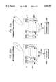
- FIGS. 2(a) and 2(b) are schematic diagrams of general array antenna system. Specifically, FIG. 2(a) is a schematic diagram of a receive array antenna system, and FIG. 2(b) is a schematic diagram of a transmit array antenna system.
- a receive array antenna system is composed of multiple antenna elements (210a-210n); a power feeder unit (220) which controls the amplitude and phase of receive signals; a power combiner or summer unit (230) which sums the signals which are received from each antenna element; and a receiver unit (240).
- a power feeder unit (220) which controls the amplitude and phase of receive signals
- a power combiner or summer unit 230 which sums the signals which are received from each antenna element
- a receiver unit 240.
- a transmit array antenna system is, as illustrated in FIG. 2(b), composed of multiple antenna elements (215a-215n); a power feeder unit (225) which controls the amplitude and phase of transmit signals; a power divider unit (235) which divides and supplies the signals which are transmitted to each antenna element; and a transmitter unit (245).
- the weights of the signals transmitted from the transmitter unit (245) are transmitted from the power divider (235) to each power feeder unit (225).
- beam patterns which will be radiated from each of the antenna elements (215a-215n) according to relevant weights (w1-wn) are determined.
- FIG. 3 is a schematic diagram of receive adaptive phase array antenna system according to prior art.
- prior receive adaptive phase array antenna system is composed of multiple antenna elements (210a-210n); a power feeder unit (220) which controls the amplitude and phase of transmit and receive signals; a power combiner (230) which sums the signals received from each antenna element; a beam adjusting processor (250); and a receiver unit (240).
- Each element (210a-210n) of the array antenna (210) is connected to an amplifier (or an attenuator) and a phase adjuster (not shown).
- Power feeders (220) connected to each antenna element (210a-210n) are connected to the receiver unit (240) through the power combiner unit (230).
- a beam adjusting processor (250) adjusts beams by computing weights (w1-wn) for each antenna element (210a-210n), and providing each antenna element with their respective weights.
- the adaptive phase array antenna system described above has the merit of being adapted to any situation because the beam patterns can be changed to an infinite number of beam patterns according to weight computing algorithms. But, in a system with many array elements, the prior adaptive phase array antenna system has to compute a great deal, and so, beam adjusting in realtime by changing signals becomes difficult. Also, because of weight computing algorithm, expensive DSP chips should be used. The result is that the above system becomes very expensive, and applying it to a general commercial system is difficult.
- a related technique paper in this field is "A Flat Four-Beam Switched Array Antenna” disclosed in IEEE Trans. Antenna and Propagation, Vol.44, No.9, 1996. This paper discloses a method of obtaining a fixed beam in multiple directions using switches. But this method allows only a small number (4) of beams patterns.
- the adaptive phase array antenna uses weights computed in advance and stores them using the weight memory unit. This results in saving the time which is needed to compute weights, and allows realtime processing of beams.
- a preferred embodiment of a transmit and receive adaptive phased array antenna system using a weight memory unit including a transmitter unit; a power divider unit which is connected to said transmitter unit, and, when transmitting, divides power according to pre-computed weights; a receiver unit; an array antenna unit wherein multiple antenna elements of said antenna system are spatially arrayed; a power feeder unit which, when receiving, receives received signals from said array antenna unit and changes amplitude and phase of the received signals according to another control signal, and, when transmitting, receives divided signals from said power divider unit; a power combiner unit which sums received signals received from said power feeder unit, using weights; an amplitude detector unit which checks the amplitude of the signals which are received from said power combiner unit, and transmits them to said receiver unit; a beam control unit which receives amplitudes of summed signals from said amplitude detector, and adjusts beam direction of the antenna, and compares field intensity which is received from each direction, and finds an optimized path; and a weight memory unit which is
- a preferred embodiment of a apparatus for receive adaptive phased array antenna system including an array antenna unit wherein basic antenna elements are spatially arrayed; a power feeder unit which receives receive signals from said array antenna; a power combiner unit which sums signals coming from said power feeder unit and, combines them into one signal; an amplitude detector unit which detects strength of said receive signals; a beam control unit which receives detected amplitudes of signals from said amplitude detector; a weight memory unit which is commanded by said beam control unit to provide said power feeder unit with weights which befit directions of the beam selected by said beam control unit; and a receiver unit which receives output signals of said power combiner.
- FIG. 1 is a schematic diagram of general switched beam antenna system
- FIGS. 2(a) and 2(b) are a schematic diagrams of general array antenna system
- FIG. 3 is an adaptive phase array antenna system according to prior art
- FIG. 4 is a schematic diagram of receive adaptive phase array antenna system according to the present invention.
- FIG. 5 is a schematic diagram of transmit and receive adaptive phase array antenna system according to the present invention.
- FIG. 6 is a flow chart of transmit and receive adaptive phase array antenna system according to the present invention.
- Prior adaptive phase array antenna system finds the position of input signals in realtime and computes weights for the array.
- the present invention computes weights of array in advance and stores them in a memory unit. At the time of changing the direction of the beam of the antenna, the weights in the memory unit are read, and the amplitude and phase of the signals which are transmitted or receives from each antenna element is adjusted.
- FIG. 4 is a schematic diagram of an exemplary receive adaptive phase array antenna system according to the present invention.
- a preferred embodiment of the receive adaptive phase array antenna system according to the present invention is composed of an array antenna unit (410) wherein basic antenna elements (410a-410n) are spatially arrayed; a power feeder unit (420) which receives receive signals from the array antenna (410); a power combiner unit (430) which sums signals coming from the power feeder unit (420) and, combines them into one signal; an amplitude detector unit (440) which detects the strength of the receive signals; a beam control unit (460) which receives the detected amplitude of signals from the amplitude detector; a weight memory unit (470) which is commanded by the beam control unit (460) to provide the power feeder unit (420) with weights which befit the direction of the receive signal; and a receiver unit (450)which transmits output signals of the power combiner unit (430).
- the power feeder unit (420) In this case, nearly any kind of antenna can be utilized.
- Each antenna element (410a-410n) comprising the array antenna unit (410) is connected to an amplifier (or an attenuator) and a phase adjuster of the power feeder unit (420).
- Each of the power feeder circuits of power feeder unit (420) is connected to a respective antenna element (410a-410n) of array antenna unit (410).
- the power feeder circuits are composed of an amplifier or an attenuator and a phase shifter, and change the amplitude and phase of the signals which are received from each antenna element, according to the command fixed by beam control unit (460).
- the power combiner unit (430) sums the signals coming from each antenna power feeder circuit into one signal, and transmits it to receiver unit (450).
- the structure of power combiner unit (430) is determined according to the pattern of transmit lines from the power feeder unit (420).
- the amplitude detector unit (440) which is connected between the receiver unit (450) and the power combiner unit (430) detects the strength of receive signals.
- the amplitude detector unit (440) detects the amplitude of summed signals and transmit it to the beam control unit (460).
- the beam control unit (460) is composed of microprocessors or DSP chips, and comparing the amplitude of receive signals which are received from various directions, adjusts the beams to the desired direction.
- the beam control unit (460) commands the weight memory unit (470) to provide power feeder unit (420) with weights which are proper for a given direction, and when the amplitude of the signal attenuates suddenly, for instance, finds a new receiving direction.
- the weight memory unit (470) may be composed of ROMs (Read Only Memories) or any other type of memory elements capable of storing weights which are pre-computed to adjust the beam direction of antenna.
- the weight memory unit (470) transfers weights chosen by the command of the beam control unit (460), to power feeder unit (420).
- the structure of the antenna explained above is for receiving, but the structure for transmitting is basically the same.
- An antenna for transmitting does not need an amplitude detector unit (440) which is needed to determine the receiving direction, and has a power divider instead of a power combiner (430).
- the power feeder unit (420) contains an amplifier.
- Signals received from a transmitter unit are provided to each power feeder circuit with equal power by a power divider, and the beam control unit perform proper amplifying and phase shifting according to the weights which are stored in a weight memory unit, and transfers the signals to antenna elements.
- Each antenna element radiates the provided power, and in case same weights are given, the antenna pattern for transmitting and receiving is same.
- FIG. 5 is a schematic diagram of a transmit and receive adaptive phase array antenna system according to the present invention.
- a preferred embodiment of a transmit and receive adaptive phase array antenna system according to the present invention is composed of a transmitter unit (560); a power divider unit (530) which is connected to the transmitter unit (560), and, when transmitting, divides computed weights; a receiver unit (570); an array antenna unit (510) wherein multiple basic elements of the antenna are spatially arrayed; a power feeder unit (520) which, when receiving, receives receive signals from the array antenna unit(510) and changes the amplitude and phase of the receive signals according to another control signal, and, when transmitting, receives divided signals from the power divider unit (530); a power combiner unit (540) which sums receive signals, which are received from the power feeder unit (520) using weights; an amplitude detector unit (550) which checks the amplitude of the signals which are received from the power combiner unit (540), and transmits them to the receiver unit (570);
- antenna Since the lower part of antenna can be connected to a circulator or an Ortho-Mode-Transducer (OMT), received signals are transmitted to the receiver, and signals provided from transmitter are radiated through antenna.
- OMT Ortho-Mode-Transducer
- FIG. 6 is a flow chart of the transmit and receive adaptive phase array antenna system according to the present invention.
- the beam control unit (590) moves the beam direction in a prescribed order, providing the phase shifter and amplitude adjuster of the power feeder unit (520) with the weights (w1-wn) which are stored in weight memory unit (580), at step (620).
- the amplitude detector unit (550) finds the strength of the field which is received according to each beam angle, and stores it in another part of the memory unit (580), at step (630).
- the beam control unit (590) compares the receiving field intensity of various directions on the basis of the scanned values.
- the angle with the biggest receiving strength among the scanned beams is selected, at step (640).
- step (650) the beam is moved to direction which was selected at step (640), and at step (660), data is transmitted or received to/from chosen direction.
- the beam control unit (590) continuously observes the strength of received signals which are obtained from the amplitude detector (550), and steering to new maximum beam direction according to the change of the strength of received signals, communication can always be possible.
- step (670) when the receiving intensity of antenna becomes small abruptly, for instance, it is judged that signal blocking has occurred, and the system returns to step (620), where the beam is rescanned, and the new beam direction which has maximum receiving field is found.
- a multi-beam antenna can be easily embodied.
- the best beam when physical characteristics of array antenna e.g. coupling or loss
- the best beam when physical characteristics of array antenna can be embodied, and more various beam characteristics can be obtained compared to a switched beam antenna.
Abstract
Description
Claims (13)
Applications Claiming Priority (2)
| Application Number | Priority Date | Filing Date | Title |
|---|---|---|---|
| KR1019970037195A KR100468820B1 (en) | 1997-08-04 | 1997-08-04 | Adaptive phased array antenna using weight memory unit |
| KR97-37195 | 1997-08-04 |
Publications (1)
| Publication Number | Publication Date |
|---|---|
| US6049307A true US6049307A (en) | 2000-04-11 |
Family
ID=19516831
Family Applications (1)
| Application Number | Title | Priority Date | Filing Date |
|---|---|---|---|
| US09/129,172 Expired - Lifetime US6049307A (en) | 1997-08-04 | 1998-08-04 | Adaptive phased array antenna using weight memory unit |
Country Status (6)
| Country | Link |
|---|---|
| US (1) | US6049307A (en) |
| JP (1) | JPH11127019A (en) |
| KR (1) | KR100468820B1 (en) |
| DE (1) | DE19834920A1 (en) |
| FR (1) | FR2766994B1 (en) |
| GB (1) | GB2328320B (en) |
Cited By (35)
| Publication number | Priority date | Publication date | Assignee | Title |
|---|---|---|---|---|
| US6369758B1 (en) | 2000-11-01 | 2002-04-09 | Unique Broadband Systems, Inc. | Adaptive antenna array for mobile communication |
| US20020103013A1 (en) * | 2001-01-31 | 2002-08-01 | Watson Stephen J. | Signal detection using a phased array antenna |
| US6473055B2 (en) | 2000-04-17 | 2002-10-29 | Toshiba Tec Kabushiki Kaisha | Directional antenna apparatus and mobile communication system using the same |
| US20020187814A1 (en) * | 2001-06-06 | 2002-12-12 | Nec Corporation | Adaptive antenna reception apparatus with weight updated adaptively |
| US6496142B1 (en) * | 1998-10-30 | 2002-12-17 | Sanyo Electric Co., Ltd | Adaptive array device |
| EP1267443A2 (en) * | 2001-06-12 | 2002-12-18 | Mobisphere Ltd. | Improvements in or relating to smart antenna arrays |
| US6597678B1 (en) * | 1999-02-01 | 2003-07-22 | Hitachi, Ltd. | Radio communication system using adaptive array antenna |
| US20040056800A1 (en) * | 2000-12-29 | 2004-03-25 | Esa Tiirola | Base station, base station module and method for estimating parameters of uplink signals |
| US6763062B1 (en) * | 1999-05-24 | 2004-07-13 | Toshiba Tec Kabushiki Kaisha | Radio communication system |
| US20040147290A1 (en) * | 2003-01-22 | 2004-07-29 | Tohru Kikuchi | Directional antenna control device, beam selecting method therefor, and program |
| US20040192239A1 (en) * | 2003-03-27 | 2004-09-30 | Sanyo Electric Co., Ltd. | Transmission method and radio apparatus utilizing the same |
| US20040224629A1 (en) * | 2001-08-01 | 2004-11-11 | Sung-Joon Moon | Antenna apparatus of relay system |
| US20050159187A1 (en) * | 2002-03-18 | 2005-07-21 | Greg Mendolia | Antenna system and method |
| US20050206564A1 (en) * | 2004-03-19 | 2005-09-22 | Comware, Inc. | Adaptive beam-forming system using hierarchical weight banks for antenna array in wireless communication system |
| US20060238400A1 (en) * | 2002-11-04 | 2006-10-26 | Vivato, Inc. | Forced Beam Switching in Wireless Communication Systems having Smart Antennas |
| US20080150794A1 (en) * | 2006-07-26 | 2008-06-26 | Junichiro Suzuki | Weight calculation method, weight calculation device, adaptive array antenna, and radar device |
| US20110050489A1 (en) * | 2009-08-26 | 2011-03-03 | Maenpa Jon E | System and method for correcting global navigation satellite system pseudorange measurements in receivers having controlled reception pattern antennas |
| US20110050497A1 (en) * | 2009-08-26 | 2011-03-03 | Maenpa Jon E | System and method for correcting global navigation satellite system carrier phase measurements in receivers having controlled reception pattern antennas |
| CN101227214B (en) * | 2007-01-15 | 2011-04-20 | 中国移动通信集团设计院有限公司 | Intelligent antenna setting method of code division multiple access system |
| US8154445B2 (en) | 2010-03-30 | 2012-04-10 | Raytheon Company | System and method for frequency domain correction of global navigation satellite system pseudorance measurements in receivers having controlled reception pattern antennas |
| US20120299773A1 (en) * | 2011-05-23 | 2012-11-29 | Sony Coropration | Beam forming device and method |
| US20120326942A1 (en) * | 2011-06-21 | 2012-12-27 | Broadcom Corporation | Sectorized Antenna |
| RU2518428C2 (en) * | 2012-06-26 | 2014-06-10 | Закрытое акционерное общество "Комплексный технический сервис" | Direction finding phase method and phase direction finder for implementing said method |
| RU2519593C2 (en) * | 2012-08-15 | 2014-06-20 | Федеральное государственное военное образовательное учреждение высшего профессионального образования "Военный авиационный инженерный университет" (г. Воронеж) Министерства обороны Российской Федерации | Phase direction finder |
| CN104685843A (en) * | 2013-09-30 | 2015-06-03 | 华为技术有限公司 | Antenna and communication device |
| US9106286B2 (en) | 2000-06-13 | 2015-08-11 | Comcast Cable Communications, Llc | Network communication using diversity |
| US20170214512A1 (en) * | 2015-08-06 | 2017-07-27 | Huizhou Tcl Mobile Communication Co., Ltd | Co-frequency and co-time full duplex terminal for receiving and transmitting signal using common antenna and communication method thereof |
| US9973291B2 (en) * | 2016-02-18 | 2018-05-15 | The United States Of America, As Represented By The Secretary Of The Army | Combined signal produced from signal copies |
| US10009085B2 (en) | 2002-11-04 | 2018-06-26 | Xr Communications, Llc | Directed wireless communication |
| EP3346619A1 (en) | 2010-05-02 | 2018-07-11 | ViaSat, Inc. | Flexible capacity satellite communications system |
| US10498433B2 (en) | 2010-05-02 | 2019-12-03 | Viasat, Inc. | Flexible capacity satellite communications system |
| US10511379B2 (en) | 2010-05-02 | 2019-12-17 | Viasat, Inc. | Flexible beamforming for satellite communications |
| US10784937B2 (en) | 2019-01-02 | 2020-09-22 | Rfcore Co., Ltd. | Beamformer including signal detector for compensating weights, wireless transmitting and receiving device including beamformer, and operating method of wireless transmitting and receiving device including beamformer |
| CN112292799A (en) * | 2018-07-06 | 2021-01-29 | 欧姆龙株式会社 | Wireless power supply device and wireless power supply system |
| US10985833B2 (en) | 2017-04-10 | 2021-04-20 | Viasat, Inc. | Coverage area adjustment to adapt satellite communications |
Families Citing this family (14)
| Publication number | Priority date | Publication date | Assignee | Title |
|---|---|---|---|---|
| KR100689398B1 (en) * | 1999-10-09 | 2007-03-08 | 삼성전자주식회사 | Method and apparatus for controling transmit antenna diversity of mobile communication system |
| US6819243B2 (en) | 2000-04-03 | 2004-11-16 | Mikko Keskilammi | Method and apparatus for identifying bulk goods, preferably roll-like bulk goods |
| FI20000851A (en) | 2000-04-10 | 2001-10-11 | Nokia Networks Oy | Communication method and radio system |
| JP2002237766A (en) * | 2001-02-08 | 2002-08-23 | Nec Corp | Adaptive antenna receiving device |
| GB0126256D0 (en) * | 2001-11-01 | 2002-01-02 | Antenova Ltd | Adaptive radio antennas |
| US7324784B2 (en) * | 2003-03-12 | 2008-01-29 | Nec Corporation | Transmission beam control method, adaptive antenna transmitter/receiver apparatus and radio base station |
| US7414579B2 (en) * | 2004-09-23 | 2008-08-19 | Interdigital Technology Corporation | Blind signal separation using correlated antenna elements |
| KR101067367B1 (en) * | 2009-02-27 | 2011-09-23 | 한국과학기술원 | Apparatus and method for accessing radio network using beam scanning scheme |
| ES2429416B1 (en) * | 2012-05-10 | 2014-11-21 | Vodafone España, S.A.U. | ACTIVE ANTENNA CONTROLLER AND SAME CONTROL PROCEDURE |
| KR101985909B1 (en) * | 2018-01-04 | 2019-06-04 | 연세대학교 산학협력단 | System and method for ultra high speed far-field correction of phased array antenna |
| WO2020158961A1 (en) * | 2019-01-28 | 2020-08-06 | 엘지전자 주식회사 | Electronic device including antenna |
| CN110544835B (en) * | 2019-09-02 | 2021-01-12 | 中国电子科技集团公司第五十四研究所 | Active plane angle diversity antenna for beyond-line-of-sight wireless communication |
| KR102327211B1 (en) * | 2020-08-12 | 2021-11-15 | 국방과학연구소 | Array antenna device, beam steering device and method for beam steering |
| CN113037318B (en) * | 2021-02-25 | 2023-03-14 | 成都老鹰信息技术有限公司 | Low-cost miniaturized communication-in-motion antenna and phased array system based on same |
Citations (6)
| Publication number | Priority date | Publication date | Assignee | Title |
|---|---|---|---|---|
| US4280128A (en) * | 1980-03-24 | 1981-07-21 | The United States Of America As Represented By The Secretary Of The Army | Adaptive steerable null antenna processor |
| US5243354A (en) * | 1992-08-27 | 1993-09-07 | The United States Of America As Represented By The Secretary Of The Army | Microstrip electronic scan antenna array |
| US5327143A (en) * | 1992-06-22 | 1994-07-05 | Trw Inc. | Multiple arm spiral antenna system with multiple beamforming capability |
| US5471220A (en) * | 1994-02-17 | 1995-11-28 | Itt Corporation | Integrated adaptive array antenna |
| US5856804A (en) * | 1996-10-30 | 1999-01-05 | Motorola, Inc. | Method and intelligent digital beam forming system with improved signal quality communications |
| US5917447A (en) * | 1996-05-29 | 1999-06-29 | Motorola, Inc. | Method and system for digital beam forming |
Family Cites Families (11)
| Publication number | Priority date | Publication date | Assignee | Title |
|---|---|---|---|---|
| GB2189348B (en) * | 1979-05-23 | 1988-04-20 | Standard Telephones Cables Ltd | Adaptive antenna arrays for frequency hopped systems |
| US4490721A (en) * | 1980-11-17 | 1984-12-25 | Ball Corporation | Monolithic microwave integrated circuit with integral array antenna |
| US4489325A (en) * | 1983-09-02 | 1984-12-18 | Bauck Jerald L | Electronically scanned space fed antenna system and method of operation thereof |
| FR2560447B1 (en) * | 1984-02-24 | 1988-04-08 | Thomson Csf | NETWORK ANTENNA AND RADAR OF REDUCED SENSITIVITY TO INTERFERENCE |
| US4670756A (en) * | 1986-04-07 | 1987-06-02 | Hazeltine Corporation | Phase shifter control |
| US5036333A (en) * | 1990-06-21 | 1991-07-30 | Hughes Aircraft Company | Antenna-rotation compensation apparatus and method for phased array antennas |
| JP2684888B2 (en) * | 1991-08-06 | 1997-12-03 | 国際電信電話株式会社 | Adaptive array antenna control method |
| GB2265053B (en) * | 1992-03-11 | 1995-11-01 | Roke Manor Research | Digital signal receiver and communications systems |
| CA2215788A1 (en) * | 1995-03-20 | 1996-09-26 | Siemens Aktiengesellschaft | Fixed station of mobile radio system |
| GB2309616B (en) * | 1996-01-27 | 2000-05-17 | Motorola Ltd | A space division multiple access radio communication system and method for allocating channels therein |
| US5754138A (en) * | 1996-10-30 | 1998-05-19 | Motorola, Inc. | Method and intelligent digital beam forming system for interference mitigation |
-
1997
- 1997-08-04 KR KR1019970037195A patent/KR100468820B1/en active IP Right Grant
-
1998
- 1998-08-03 DE DE19834920A patent/DE19834920A1/en not_active Ceased
- 1998-08-04 GB GB9816829A patent/GB2328320B/en not_active Expired - Fee Related
- 1998-08-04 US US09/129,172 patent/US6049307A/en not_active Expired - Lifetime
- 1998-08-04 FR FR9810003A patent/FR2766994B1/en not_active Expired - Fee Related
- 1998-08-04 JP JP10220880A patent/JPH11127019A/en active Pending
Patent Citations (6)
| Publication number | Priority date | Publication date | Assignee | Title |
|---|---|---|---|---|
| US4280128A (en) * | 1980-03-24 | 1981-07-21 | The United States Of America As Represented By The Secretary Of The Army | Adaptive steerable null antenna processor |
| US5327143A (en) * | 1992-06-22 | 1994-07-05 | Trw Inc. | Multiple arm spiral antenna system with multiple beamforming capability |
| US5243354A (en) * | 1992-08-27 | 1993-09-07 | The United States Of America As Represented By The Secretary Of The Army | Microstrip electronic scan antenna array |
| US5471220A (en) * | 1994-02-17 | 1995-11-28 | Itt Corporation | Integrated adaptive array antenna |
| US5917447A (en) * | 1996-05-29 | 1999-06-29 | Motorola, Inc. | Method and system for digital beam forming |
| US5856804A (en) * | 1996-10-30 | 1999-01-05 | Motorola, Inc. | Method and intelligent digital beam forming system with improved signal quality communications |
Non-Patent Citations (2)
| Title |
|---|
| Kuga, Nobuhiro and Hiroyuki Arai, "A Flat Four-Beam Switched Array Antenna," IEEE Transaction on Antennas and Propagation, vol. 44. No. 9, Sep. 1996, pp. 1227-1230. |
| Kuga, Nobuhiro and Hiroyuki Arai, A Flat Four Beam Switched Array Antenna, IEEE Transaction on Antennas and Propagation, vol. 44. No. 9, Sep. 1996, pp. 1227 1230. * |
Cited By (80)
| Publication number | Priority date | Publication date | Assignee | Title |
|---|---|---|---|---|
| US6496142B1 (en) * | 1998-10-30 | 2002-12-17 | Sanyo Electric Co., Ltd | Adaptive array device |
| US20040014501A1 (en) * | 1999-02-01 | 2004-01-22 | Mikio Kuwahara | Radio communication system using adaptive array antenna |
| US6597678B1 (en) * | 1999-02-01 | 2003-07-22 | Hitachi, Ltd. | Radio communication system using adaptive array antenna |
| US7082321B2 (en) * | 1999-02-01 | 2006-07-25 | Hitachi, Ltd. | Radio communication system using adaptive array antenna |
| US6763062B1 (en) * | 1999-05-24 | 2004-07-13 | Toshiba Tec Kabushiki Kaisha | Radio communication system |
| US6473055B2 (en) | 2000-04-17 | 2002-10-29 | Toshiba Tec Kabushiki Kaisha | Directional antenna apparatus and mobile communication system using the same |
| US9106286B2 (en) | 2000-06-13 | 2015-08-11 | Comcast Cable Communications, Llc | Network communication using diversity |
| USRE45775E1 (en) | 2000-06-13 | 2015-10-20 | Comcast Cable Communications, Llc | Method and system for robust, secure, and high-efficiency voice and packet transmission over ad-hoc, mesh, and MIMO communication networks |
| US9197297B2 (en) | 2000-06-13 | 2015-11-24 | Comcast Cable Communications, Llc | Network communication using diversity |
| US9209871B2 (en) | 2000-06-13 | 2015-12-08 | Comcast Cable Communications, Llc | Network communication using diversity |
| US9515788B2 (en) | 2000-06-13 | 2016-12-06 | Comcast Cable Communications, Llc | Originator and recipient based transmissions in wireless communications |
| US9820209B1 (en) | 2000-06-13 | 2017-11-14 | Comcast Cable Communications, Llc | Data routing for OFDM transmissions |
| US10257765B2 (en) | 2000-06-13 | 2019-04-09 | Comcast Cable Communications, Llc | Transmission of OFDM symbols |
| USRE45807E1 (en) | 2000-06-13 | 2015-11-17 | Comcast Cable Communications, Llc | Apparatus for transmitting a signal including transmit data to a multiple-input capable node |
| US9356666B1 (en) | 2000-06-13 | 2016-05-31 | Comcast Cable Communications, Llc | Originator and recipient based transmissions in wireless communications |
| US9722842B2 (en) | 2000-06-13 | 2017-08-01 | Comcast Cable Communications, Llc | Transmission of data using a plurality of radio frequency channels |
| US9391745B2 (en) | 2000-06-13 | 2016-07-12 | Comcast Cable Communications, Llc | Multi-user transmissions |
| US9401783B1 (en) | 2000-06-13 | 2016-07-26 | Comcast Cable Communications, Llc | Transmission of data to multiple nodes |
| US9344233B2 (en) | 2000-06-13 | 2016-05-17 | Comcast Cable Communications, Llc | Originator and recipient based transmissions in wireless communications |
| US9654323B2 (en) | 2000-06-13 | 2017-05-16 | Comcast Cable Communications, Llc | Data routing for OFDM transmission based on observed node capacities |
| US10349332B2 (en) | 2000-06-13 | 2019-07-09 | Comcast Cable Communications, Llc | Network communication using selected resources |
| US6369758B1 (en) | 2000-11-01 | 2002-04-09 | Unique Broadband Systems, Inc. | Adaptive antenna array for mobile communication |
| US6999796B2 (en) * | 2000-12-29 | 2006-02-14 | Nokia Corporation | Base station, base station module and method for estimating parameters of uplink signals |
| US20040056800A1 (en) * | 2000-12-29 | 2004-03-25 | Esa Tiirola | Base station, base station module and method for estimating parameters of uplink signals |
| US20020103013A1 (en) * | 2001-01-31 | 2002-08-01 | Watson Stephen J. | Signal detection using a phased array antenna |
| EP1229342A2 (en) * | 2001-01-31 | 2002-08-07 | Qinetiq Limited | Signal detection using a phased array antenna |
| EP1229342A3 (en) * | 2001-01-31 | 2004-01-07 | Qinetiq Limited | Signal detection using a phased array antenna |
| US20020187814A1 (en) * | 2001-06-06 | 2002-12-12 | Nec Corporation | Adaptive antenna reception apparatus with weight updated adaptively |
| US7106785B2 (en) * | 2001-06-06 | 2006-09-12 | Nec Corporation | Adaptive antenna reception apparatus with weight updated adaptively |
| EP1267443A2 (en) * | 2001-06-12 | 2002-12-18 | Mobisphere Ltd. | Improvements in or relating to smart antenna arrays |
| US6795018B2 (en) * | 2001-06-12 | 2004-09-21 | Mobisphere Limited | Smart antenna arrays |
| EP1267443A3 (en) * | 2001-06-12 | 2003-09-03 | Mobisphere Ltd. | Improvements in or relating to smart antenna arrays |
| US7146131B2 (en) * | 2001-08-01 | 2006-12-05 | R-Tron Inc. | Antenna apparatus of relay system |
| US20040224629A1 (en) * | 2001-08-01 | 2004-11-11 | Sung-Joon Moon | Antenna apparatus of relay system |
| US20050159187A1 (en) * | 2002-03-18 | 2005-07-21 | Greg Mendolia | Antenna system and method |
| US20060238400A1 (en) * | 2002-11-04 | 2006-10-26 | Vivato, Inc. | Forced Beam Switching in Wireless Communication Systems having Smart Antennas |
| US10009085B2 (en) | 2002-11-04 | 2018-06-26 | Xr Communications, Llc | Directed wireless communication |
| US11777569B2 (en) | 2002-11-04 | 2023-10-03 | Xr Communications Llc | Directed wireless communication |
| US7729728B2 (en) * | 2002-11-04 | 2010-06-01 | Xr Communications, Llc | Forced beam switching in wireless communication systems having smart antennas |
| US10715235B2 (en) | 2002-11-04 | 2020-07-14 | Xr Communications, Llc | Directed wireless communication |
| US10594376B2 (en) | 2002-11-04 | 2020-03-17 | Xr Communications, Llc | Directed wireless communication |
| US20040147290A1 (en) * | 2003-01-22 | 2004-07-29 | Tohru Kikuchi | Directional antenna control device, beam selecting method therefor, and program |
| US7233283B2 (en) * | 2003-01-22 | 2007-06-19 | Nec Corporation | Directional antenna control device, beam selecting method therefor, and program |
| US20040192239A1 (en) * | 2003-03-27 | 2004-09-30 | Sanyo Electric Co., Ltd. | Transmission method and radio apparatus utilizing the same |
| US7209713B2 (en) * | 2003-03-27 | 2007-04-24 | Sanyo Electric Co., Ltd. | Transmission method and radio apparatus for substantially constant receiving power level at a remote terminal |
| US7312750B2 (en) | 2004-03-19 | 2007-12-25 | Comware, Inc. | Adaptive beam-forming system using hierarchical weight banks for antenna array in wireless communication system |
| US20050206564A1 (en) * | 2004-03-19 | 2005-09-22 | Comware, Inc. | Adaptive beam-forming system using hierarchical weight banks for antenna array in wireless communication system |
| WO2005091525A1 (en) * | 2004-03-19 | 2005-09-29 | Comware, Inc. | Adaptive beam-forming system using hierarchical weight banks for antenna array in wireless communication systems |
| US7535410B2 (en) * | 2006-07-26 | 2009-05-19 | Kabushiki Kaisha Toshiba | Weight calculation method, weight calculation device, adaptive array antenna, and radar device |
| US20080150794A1 (en) * | 2006-07-26 | 2008-06-26 | Junichiro Suzuki | Weight calculation method, weight calculation device, adaptive array antenna, and radar device |
| CN101227214B (en) * | 2007-01-15 | 2011-04-20 | 中国移动通信集团设计院有限公司 | Intelligent antenna setting method of code division multiple access system |
| US8044857B2 (en) | 2009-08-26 | 2011-10-25 | Raytheon Company | System and method for correcting global navigation satellite system pseudorange measurements in receivers having controlled reception pattern antennas |
| US20110050489A1 (en) * | 2009-08-26 | 2011-03-03 | Maenpa Jon E | System and method for correcting global navigation satellite system pseudorange measurements in receivers having controlled reception pattern antennas |
| US20110050497A1 (en) * | 2009-08-26 | 2011-03-03 | Maenpa Jon E | System and method for correcting global navigation satellite system carrier phase measurements in receivers having controlled reception pattern antennas |
| US8089402B2 (en) * | 2009-08-26 | 2012-01-03 | Raytheon Company | System and method for correcting global navigation satellite system carrier phase measurements in receivers having controlled reception pattern antennas |
| US8154445B2 (en) | 2010-03-30 | 2012-04-10 | Raytheon Company | System and method for frequency domain correction of global navigation satellite system pseudorance measurements in receivers having controlled reception pattern antennas |
| US11637629B2 (en) | 2010-05-01 | 2023-04-25 | Viasat Inc. | Flexible capacity satellite communications system |
| EP3346619A1 (en) | 2010-05-02 | 2018-07-11 | ViaSat, Inc. | Flexible capacity satellite communications system |
| US10498433B2 (en) | 2010-05-02 | 2019-12-03 | Viasat, Inc. | Flexible capacity satellite communications system |
| US11909508B2 (en) | 2010-05-02 | 2024-02-20 | Viasat, Inc. | Flexible capacity satellite communications system |
| US11601195B2 (en) | 2010-05-02 | 2023-03-07 | Viasat Inc. | Flexible beamforming for satellite communications |
| US11265078B2 (en) | 2010-05-02 | 2022-03-01 | Viasat, Inc. | Flexible beamforming for satellite communications |
| US11171721B2 (en) | 2010-05-02 | 2021-11-09 | Viasat, Inc. | Flexible capacity satellite communications system |
| US10511379B2 (en) | 2010-05-02 | 2019-12-17 | Viasat, Inc. | Flexible beamforming for satellite communications |
| US9121943B2 (en) * | 2011-05-23 | 2015-09-01 | Sony Corporation | Beam forming device and method |
| US20120299773A1 (en) * | 2011-05-23 | 2012-11-29 | Sony Coropration | Beam forming device and method |
| US20120326942A1 (en) * | 2011-06-21 | 2012-12-27 | Broadcom Corporation | Sectorized Antenna |
| RU2518428C2 (en) * | 2012-06-26 | 2014-06-10 | Закрытое акционерное общество "Комплексный технический сервис" | Direction finding phase method and phase direction finder for implementing said method |
| RU2519593C2 (en) * | 2012-08-15 | 2014-06-20 | Федеральное государственное военное образовательное учреждение высшего профессионального образования "Военный авиационный инженерный университет" (г. Воронеж) Министерства обороны Российской Федерации | Phase direction finder |
| EP3043525A4 (en) * | 2013-09-30 | 2016-08-31 | Huawei Tech Co Ltd | Antenna and communication device |
| CN104685843B (en) * | 2013-09-30 | 2018-02-23 | 华为技术有限公司 | A kind of antenna and communication equipment |
| CN104685843A (en) * | 2013-09-30 | 2015-06-03 | 华为技术有限公司 | Antenna and communication device |
| US10044492B2 (en) | 2013-09-30 | 2018-08-07 | Huawei Technologies Co., Ltd. | Antenna and communications device |
| US20170214512A1 (en) * | 2015-08-06 | 2017-07-27 | Huizhou Tcl Mobile Communication Co., Ltd | Co-frequency and co-time full duplex terminal for receiving and transmitting signal using common antenna and communication method thereof |
| US9973291B2 (en) * | 2016-02-18 | 2018-05-15 | The United States Of America, As Represented By The Secretary Of The Army | Combined signal produced from signal copies |
| US10985833B2 (en) | 2017-04-10 | 2021-04-20 | Viasat, Inc. | Coverage area adjustment to adapt satellite communications |
| US11770179B2 (en) | 2017-04-10 | 2023-09-26 | Viasat, Inc. | Coverage area adjustment to adapt satellite communications |
| CN112292799A (en) * | 2018-07-06 | 2021-01-29 | 欧姆龙株式会社 | Wireless power supply device and wireless power supply system |
| CN112292799B (en) * | 2018-07-06 | 2023-09-08 | 欧姆龙株式会社 | Wireless power supply device and wireless power supply system |
| US10784937B2 (en) | 2019-01-02 | 2020-09-22 | Rfcore Co., Ltd. | Beamformer including signal detector for compensating weights, wireless transmitting and receiving device including beamformer, and operating method of wireless transmitting and receiving device including beamformer |
Also Published As
| Publication number | Publication date |
|---|---|
| JPH11127019A (en) | 1999-05-11 |
| DE19834920A1 (en) | 1999-03-04 |
| GB9816829D0 (en) | 1998-09-30 |
| FR2766994A1 (en) | 1999-02-05 |
| KR19990015228A (en) | 1999-03-05 |
| GB2328320A (en) | 1999-02-17 |
| KR100468820B1 (en) | 2005-03-16 |
| FR2766994B1 (en) | 2006-07-07 |
| GB2328320B (en) | 2000-03-15 |
Similar Documents
| Publication | Publication Date | Title |
|---|---|---|
| US6049307A (en) | Adaptive phased array antenna using weight memory unit | |
| KR100594962B1 (en) | Apparatus for Tracking Satellite Signal and Method for Tracking Satellite Signal using it | |
| US6314305B1 (en) | Transmitter/receiver for combined adaptive array processing and fixed beam switching | |
| KR100902810B1 (en) | Wireless communication method and apparatus for forming, steering and selectively receiving a sufficient number of usable beam paths in both azimuth and elevation | |
| US5894598A (en) | Radio communication system using portable mobile terminal | |
| US5041835A (en) | Electronic scanning type array antenna device | |
| EP1215751B1 (en) | Calibration method of an array antenna | |
| EP0312588B1 (en) | Multifunction active array | |
| US5592179A (en) | Frequency-hopping array antenna system | |
| US5257031A (en) | Multibeam antenna which can provide different beam positions according to the angular sector of interest | |
| JP3441326B2 (en) | Radar equipment | |
| EP0390334B1 (en) | Improved data link using electronically steerable beam | |
| US6906665B1 (en) | Cluster beam-forming system and method | |
| US6441785B1 (en) | Low sidelobe antenna with beams steerable in one direction | |
| JP3118247B2 (en) | Space-fed array antenna with dual phase shifters | |
| CA2037911C (en) | Microstrip antenna system | |
| US4580140A (en) | Twin aperture phased array lens antenna | |
| US5051753A (en) | Array antenna system with direction finding capability | |
| US4015266A (en) | Radar dipole antenna array | |
| KR102609635B1 (en) | mmWave wireless power transmission device using Rotman lens | |
| KR102609634B1 (en) | mmWave wireless power transmission device, method and system using Rotman lens | |
| KR102404183B1 (en) | Adaptive Wireless Power Transmission Apparatus, System and Method Thereof | |
| JP2851187B2 (en) | Active array antenna | |
| KR102571735B1 (en) | mmWave wireless power transmission device using virtual data link channel | |
| JPH04249784A (en) | Antenna of active phased array radar |
Legal Events
| Date | Code | Title | Description |
|---|---|---|---|
| AS | Assignment |
Owner name: SAMSUNG ELECTRONICS CO., LTD., KOREA, REPUBLIC OF Free format text: ASSIGNMENT OF ASSIGNORS INTEREST;ASSIGNOR:LIM, KYU-TAE;REEL/FRAME:009377/0909 Effective date: 19980804 |
|
| FEPP | Fee payment procedure |
Free format text: PAYOR NUMBER ASSIGNED (ORIGINAL EVENT CODE: ASPN); ENTITY STATUS OF PATENT OWNER: LARGE ENTITY |
|
| STCF | Information on status: patent grant |
Free format text: PATENTED CASE |
|
| FPAY | Fee payment |
Year of fee payment: 4 |
|
| FPAY | Fee payment |
Year of fee payment: 8 |
|
| FEPP | Fee payment procedure |
Free format text: PAYER NUMBER DE-ASSIGNED (ORIGINAL EVENT CODE: RMPN); ENTITY STATUS OF PATENT OWNER: LARGE ENTITY Free format text: PAYOR NUMBER ASSIGNED (ORIGINAL EVENT CODE: ASPN); ENTITY STATUS OF PATENT OWNER: LARGE ENTITY |
|
| FPAY | Fee payment |
Year of fee payment: 12 |